Fargo Electronics X001700 Ribbon RFID User Manual
Fargo Electronics Inc Ribbon RFID Users Manual
Contents
- 1. Users Manual
- 2. User Manual
Users Manual

HDP100 High Definition Card
Printer/Encoder User Guide (Rev.
Beta); Sections 1 to 3 (modified)
Armstrong 1x (single-Side)
Armstrong 2x (dual-Side)
Armstrong 1x L (single-side + lamination)
Armstrong 2x L (single-side + lamination)
Armstrong 2x L (dual-side + lamination)
User Guide Part Number: L000950

RESTRICTED USE ONLY Fargo Electronics, Inc.
HDP100 High Definition Card Printer/Encoder User Guide (Rev. Beta) ii
HDP100 High Definition Card Printer/Encoder User Guide (Rev. Beta), property of Fargo
Electronics, Incorporated
Copyright 2006 by Fargo Electronics, Incorporated. All rights reserved. Printed in the
United States of America. Exclusive permission is granted to authorized resellers of Fargo
products to reproduce and distribute this copyrighted document to authorized Fargo
customers. The revision number for this document will be updated to reflect changes,
corrections, updates and enhancements to this document.
Revision Control
Number Date Document Title
Revision Beta 1 January 2007 HDP100 High Definition Card
Printer/Encoder User Guide
These reference documents were thoroughly reviewed to provide Fargo with professional
and international standards, requirements, guidelines and models for our technical, training
and user documentation. At all times, the Copyright Protection Notice for each document was
adhered to within our Fargo documentation process. This reference to other documents does
not imply that Fargo is an ISO-certified company at this time.
ANSI/ISO/ASQ Q9001-2000 American National Standard, (sub-title) Quality Management
Systems – Requirements (published by the American Society of Quality, Quality Press,
P.O. Box 3005, Milwaukee, Wisconsin 53201-3005)
The ASQ ISO 9000:2000 Handbook (editors, Charles A. Cianfrani, Joseph J. Tsiakals
and John E. West; Second Edition; published by the American Society of Quality, Quality
Press, 625 N. Plankinton Avenue, Milwaukee, Wisconsin 53203)
Juran’s Quality Handbook (editors, Joseph M. Juran and A. Blanton Godfrey; Fifth
Edition, McGraw-Hill)
Any questions regarding changes, corrections, updates or enhancements to this document
should be forwarded to:
Fargo Electronics, Incorporated
Support Services
6533 Flying Cloud Drive
Eden Prairie, MN 55344 (USA)
(952) 941-9470
FAX: (952) 941-7836
www.fargo.com
E-mail: sales@fargo.com
RESTRICTED USE ONLY Fargo Electronics, Inc.
HDP100 High Definition Card Printer/Encoder User Guide (Rev. Beta) iii
Table of Contents
Section 1: Printer Overview __________________________________________________ 1
How to use the guide___________________________________________________________________1
Safety Messages (review carefully)________________________________________________________2
HDP100 Overview ____________________________________________________________________3
Reviewing the HDP100 Block Diagram__________________________________________________3
Reviewing the HDP100 Sequence of Operations___________________________________________4
Reviewing the HDP100 Boot up Sequence _______________________________________________7
Reviewing the Lamination Module Sequence of Operations __________________________________8
Reviewing the Lamination Module Boot up Sequence _____________________________________10
Section 2: Specifications_____________________________________________________ 1
Safety Messages (review carefully)________________________________________________________1
Introduction__________________________________________________________________________2
Reviewing the HDP100 Printer Overview table ______________________________________________2
Reviewing the HDP100 Package _______________________________________________________3
Reviewing the HDP100 (front)_________________________________________________________3
Reviewing the HDP100 Card Printer ____________________________________________________4
Regulatory Compliances, Agency Listings and FCC Rules _____________________________________5
Regulatory Compliances ________________________________________________________________5
Agency Listings_______________________________________________________________________6
FCC Rules ________________________________________________________________________6
Technical Specifications ________________________________________________________________7
Functional Specifications ______________________________________________________________13
Printer Components: Resin Thermal Transfer to USB Interface Port __________________________14
Printer Components: LCD and Softkey Control Pad_______________________________________16
Printer Components: Print Ribbons____________________________________________________21
Printer Components: Blank Cards _____________________________________________________22
Printer Components: Card Input and Output Hoppers______________________________________23
Printer Components: Card Output Hopper and Reject Hopper _______________________________23
Printer Unit: Reviewing the Card Lamination Module _____________________________________24
Printer Components: Transfer Roller___________________________________________________25
Reviewing the Overlaminates ___________________________________________________________26
Reviewing the Thermal Transfer Film and PolyGuard Overlaminates__________________________26
Reviewing the CR-80 Patch Size ______________________________________________________27
Reviewing the Overlaminate Design ___________________________________________________27
Section 3: General Troubleshooting ___________________________________________ 1
LCD Messages _______________________________________________________________________1
Troubleshooting LCD Messages__________________________________________________________2
General Troubleshooting Guide _______________________________________________________14
Magnetic and E-card Troubleshooting Guide_____________________________________________19
Communications Errors________________________________________________________________22
Resolving the Communication Errors___________________________________________________22
Card Feeding Errors __________________________________________________________________24
Resolving an Unable to Feed Card Error ________________________________________________24
Resolving a Card Not Fed Error (Two (2) or more card feed at the same time)___________________27
Resolving a Card Hopper Empty Error__________________________________________________29
Resolving a Card Output Hopper Full __________________________________________________30
Resolving a Card Not Fed Error (Cards will not feed off the Hopper)__________________________31
Resolving a Card Jam Error __________________________________________________________32
Resolving a Card Jam (Encoder) Error__________________________________________________33
Resolving a Card Jam (Flipper) Error___________________________________________________34
Resolving a Card Jam (Laminator) Error ________________________________________________36
RESTRICTED USE ONLY Fargo Electronics, Inc.
HDP100 High Definition Card Printer/Encoder User Guide (Rev. Beta) iv
Resolving a Card Eject Error _________________________________________________________38
Resolving a No Flipper Table Module Error _____________________________________________39
Resolving a Flipper Jam Error ________________________________________________________40
Magnetic Encoding Errors______________________________________________________________42
Resolving a Magnetic Verify Error ____________________________________________________42
Resolving a No Magnetic Encoder Installed Error_________________________________________45
Resolving a No Magnetic Strip Present Error_____________________________________________47
E-card Encoding Errors________________________________________________________________48
Resolving a No Smart Card Encoder Error_______________________________________________48
Resolving a No Prox Card Encoder Error _______________________________________________49
Film Errors _________________________________________________________________________50
Resolving a Film Not Installed Error ___________________________________________________50
Resolving a Film Sensor Not Calibrated Error____________________________________________51
Resolving a Film Out Error __________________________________________________________52
Printing Process Errors ________________________________________________________________53
Resolving a Ribbon Sensor Error (Ribbon Miscue) ________________________________________53
Resolving a Ribbon Break/Jam Error___________________________________________________55
Resolving a Ribbon Out Error ________________________________________________________57
Resolving a No Ribbon Installed Error__________________________________________________58
Resolving a Invalid Ribbon Error______________________________________________________60
Resolving a Wrong Ribbon Error______________________________________________________62
Resolving a Headlift Motor or Sensor Error______________________________________________64
Resolving the Cover Open Error Message _______________________________________________66
Resolving the Blank Output issues_____________________________________________________68
Card Lamination Errors________________________________________________________________71
Resolving a Laminator (General Error) _________________________________________________71
Resolving the Laminator (Check Power) Error ___________________________________________72
Resolving the Laminator (Heater Off) Error _____________________________________________73
Resolving the Wrong Overlaminate Installed Error ________________________________________74
Resolving Check Lamination Material Error _____________________________________________75
Resolving LAM Heater Times Out Error ________________________________________________76
Printing a Test Image _________________________________________________________________77
Reviewing the Gray/Align YMC/K Self-Test ____________________________________________77
Reviewing the Color/Resin YMCK Self-Test ____________________________________________78
Reviewing the Color Bars YMC Self-Test_______________________________________________78
Reviewing the Card Count Self-Test ___________________________________________________79
Reviewing the Magnetic Test option ___________________________________________________79
Reviewing the Lamination Color/Resin YMCK+L Self-Test ________________________________80

RESTRICTED USE ONLY Fargo Electronics, Inc.
HDP100 High Definition Card Printer/Encoder User Guide (Rev. Beta) 1
Section 1: Printer Overview
How to use the guide
The HDP100 High Definition Card Printer/Encoder User Guide (Rev. 1.0) is designed to
provide installers and technicians with quick, efficient lookup of related procedures,
components and terms. The Guide can be used effectively either in soft or hard copy,
depending on the preference of the installer or technician.
Manual Description
Glossary of Terms and
Technical/Functional
Specifications (hyper-linked)
You can go directly to the Glossary of Terms, Technical
Specifications and Functional Specifications to learn how
to use the processes, procedures, functions and windows
for the HDP100 within concise, correlative tables.
Table of Contents (hyper-
linked) You can use the automated Table of Contents to quickly
locate, for example, an error message, a procedure, the
index or an appendix.
Cross-Referencing (hyper-
linked) You can use the cross-referencing links to quickly locate,
for example, an error message or a procedure.
Comprehensive Index
(hyper-linked) You can use the Comprehensive Index to quickly locate
information on the HDP100, relating to a specification, a
procedural step, a window or screen, a component, a
term, a qualifier or a related feature to this Printer.
RESTRICTED USE ONLY Fargo Electronics, Inc.
HDP100 High Definition Card Printer/Encoder User Guide (Rev. Beta) 2
Safety Messages (review carefully)
Symbol Critical Instructions for Safety purposes
Danger:
Failure to follow these installation guidelines can result in death or
serious injury.
Information that raises potential safety issues is indicated by a warning
symbol (as shown to the left).
To prevent personal injury, refer to the following safety messages
before performing an operation preceded by this symbol.
To prevent personal injury, always remove the power cord prior to
performing repair procedures, unless otherwise specified.
To prevent personal injury, make sure only qualified personnel
perform these procedures.
Caution:
This device is electrostatically sensitive. It may be damaged if
exposed to static electricity discharges.
Information that raises potential electrostatic safety issues is indicated
by a warning symbol (as shown to the left).
To prevent equipment or media damage, refer to the following
safety messages before performing an operation preceded by this
symbol.
To prevent equipment or media damage, observe all established
Electrostatic Discharge (ESD) procedures while handling cables in
or near the Circuit Board and Printhead Assemblies.
To prevent equipment or media damage, always wear an
appropriate personal grounding device (e.g., a high quality wrist
strap grounded to avoid potential damage).
To prevent equipment or media damage, always remove the
Ribbon and Cards from the Printer before making any repairs,
unless otherwise specified.
To prevent equipment or media damage, take jewelry off of
fingers and hands, as well as thoroughly clean hands to remove oil
and debris before working on the Printer.

RESTRICTED USE ONLY Fargo Electronics, Inc.
HDP100 High Definition Card Printer/Encoder User Guide (Rev. Beta) 3
HDP100 Overview
Reviewing the HDP100 Block Diagram
The HDP100 Block Diagram will be created and added to this service document at a future
date. Should consider breaking Printer and flipper into separate block diagrams.
1
Card Input 13
Ribbon Panel Sensor 32
Card Cartridge
2
Flipper Stepper 14
Ribbon Encoder 33
3
Transfer Stepper 15
Print Headlift 34
4
Print Stepper 16
Thermistor 35
5
Transfer Headlift 17
Cover Interlock 36
6
Film Supply 18
Card Input Roller 37
7
Film Take Up 19
Cleaning Roller 38
8
Ribbon Supply 20
Flipper Table Roller 39
9
Ribbon Take Up 21
Flipper Table 40
10
Print Headlift 22
Encoding Module 41
11
Card Detection? 23
Card Feed Roller 42
12
Flipper Table Card 24
Card Feed Roller 43
13 Encoding TOF 25
Transfer Platen Roller 44
14 Flipper Home 26
Card Feed Roller 45
15 Card TOF 27
Flattener Cooling Fan 46
16 Film Transfer 28
Transfer Roller 47
17 Film Take Up
Encoder 29
Print Platen Roller 48
18 RTD (Resistive
Thermal Device) 30
Printhead 49
19 Film - Print 31
Printhead Cooling Fan 50

RESTRICTED USE ONLY Fargo Electronics, Inc.
HDP100 High Definition Card Printer/Encoder User Guide (Rev. Beta) 4
Reviewing the HDP100 Sequence of Operations
The following sequence describes a dual sided full color print job with magnetic encoding.
Step
Process
1 The File information is received from the PC.
2 The Heater warms up and/or maintains the heat on the hot Roller using the RTD
(Resistive Thermal Device) to help maintain the desired temp.
3 The DC Motor and Stepper Motor turn ON and run until a card is seen by the card
Sensor, which will cause the Card Input Motor to stop.
The Stepper will continue to run a certain number of steps to position the card
under the Card Feed/Position Sensor.
4 For a magnetic print job, the Stepper will continue moving the card until the trailing
edge is positioned under the Mag Head. All stop.
5 Stepper will turn ON in reverse direction and encode card. All stop.
6 Stepper will again turn on and position the trailing edge of the card under the Mag
Head. All stop.
7 Stepper will turn ON in reverse direction and verify data encoded onto mag stripe.
8 Stepper continues transporting card until the trailing edge is positioned under the
Card Feed/Position Sensor. All stop.
9 The Ribbon Drives turn ON and move until the correct panel is found by the Print
Ribbon Sensor. All stop. (Note: The Print Ribbon Encoder is active during this
step.)
This step occurs simultaneously with Step 10 (below).
10 The Film Drives turn ON until the Film is positioned with the Film Print Alignment
Sensor. (Note: This is the closest Sensor to the Print Platen Roller.)
All stop. (Note: The Film Ribbon Encoder is active during this step.)
11 The Headlift Motor engages, moving the Printhead down until Headlift Sensor is
activated. All stop.
Continued on the next page

RESTRICTED USE ONLY Fargo Electronics, Inc.
HDP100 High Definition Card Printer/Encoder User Guide (Rev. Beta) 5
Reviewing HDP 100 Series Card Printer – Sequence of Operations (continued)
Step
Process
12 The Fan turns ON as required to keep head cool.
13 The Ribbon Drives, Film Drive and Print Platen Stepper turn ON and the Printhead
burns the image data until the image data is depleted. All stop. (Note: The Ribbon
Encoders and Film Encoders are active during this step.)
14 The Headlift Motor engages, moving the Printhead up until the Headlift Sensor is
activated. All stop.
15 Repeat Steps 9 to 14 for the appropriate number of color/heat seal panels.
Continued on the next page

RESTRICTED USE ONLY Fargo Electronics, Inc.
HDP100 High Definition Card Printer/Encoder User Guide (Rev. Beta) 6
Reviewing HDP 100 Series Card Printer – Sequence of Operations (continued)
Step
Process
23 The Film Drives turn ON to rewind the printed portion of the Film into position at
the heated Transfer Roller using the Lamination Film Alignment Sensor.
24 If the heater is not at the required temperature yet, the job will pause.
25 Stepper engages to move the card to a position directly under the hot Roller. The
Card Feed/Position Sensor determines card edge and number of steps to position
card. All stop.
26 The Headlift Motor turns ON to lower the hot Roller and will stop when the Headlift
Sensor is activated. All stop.
27 The Stepper and Film Drive engage to laminate the printed Film onto the card.
They will turn off after a given number of steps based on the position given by the
card Sensor. All stop. (Note: The Film Encoder is active during this step.)
28 The Headlift Motor turns ON to raise the hot Roller, stopping when the Headlift
Sensor is activated.
29 The Film Drive and Stepper turn ON for a given number of clicks based on Film
Encoder, until the film is released.
30 The Stepper turns ON to move the card into Flipper Module to flip the card to the
opposite side. After flipping the card is transported back to the Card Feed/Position
Sensor to repeat Steps 9 to 14. Upon completion of print all print cycles the card
is transported to the Output Hopper (based on steps from a known from Flipper
Card Position Sensor). All stop.
31 The Heater is maintained at a set temperature by the RTD when the Printer is ON.
The cooling fan is ON when the Printhead is ON or hot.

RESTRICTED USE ONLY Fargo Electronics, Inc.
HDP100 High Definition Card Printer/Encoder User Guide (Rev. Beta) 7
Reviewing the HDP100 Boot up Sequence
Step Process
1 The Card feed stepper turns ON (to check for a card on the Flipper table).
2 The Lam Headlift turns until the head up position is returned from the Headlift
Sensor).
3 The Film transfer take-up Motor turns ON to take up any slack in the film.
4 The Print Headlift turns until head up position is returned from Headlift Sensor.
5 The Print Ribbon moves forward until it finds the yellow panel, pauses, advances
to magenta, then backs up to yellow (the Ribbon Sensor detects marks on the
ribbon).
6 The Transfer Ribbon advances forward two panels from supply (advances until
the Print Film Sensor senses 2 marks on the Film).
7 The Transfer Ribbon advances forward one panel from supply (advances until
the Print Film Sensor senses 1 mark on the Film).
8 The Transfer Ribbon reverses for one panel onto supply (reverses until the Print
Film Sensor senses 1 mark on the Film).
9 The Transfer Ribbon reverses for one panel onto supply (reverses until the Print
Film Sensor senses 1 mark on the Film).

RESTRICTED USE ONLY Fargo Electronics, Inc.
HDP100 High Definition Card Printer/Encoder User Guide (Rev. Beta) 8
Reviewing the Lamination Module Sequence of Operations
(Should this entire section be removed and added to the SEALS user manual or is the
Armstrong+flipper+SEALS to be contained in one all-inclusive manual?)
The LAM sequence of operations begins after printing has occurred with the Card Printer.
Step
Process
1 The card is fed onto the Lamination Module Flipper Table.
2 The card is fed to the Card Position Sensor.
3 The Lamination Ribbon Motor begins cycling until the Lamination Sensor detects
the mark.
4 The Card Feed Motor activates to center the card on the Platen Roller.
5 The Transfer Roller Lift Motor cycles until the Transfer Roller Lift Sensor detects
state change.
Continued on the next page

RESTRICTED USE ONLY Fargo Electronics, Inc.
HDP100 High Definition Card Printer/Encoder User Guide (Rev. Beta) 9
Reviewing the Lamination Module Sequence of Operations (continued)
Step
Process
6 The Card Feed Motor and the Lamination Ribbon Motor activate for the length of
the card.
7 The Transfer Roller Lift Motor cycles until the Transfer Roller Lift Sensor detects
state change.
8 The card is fed back to the Flipper Table.
9 The Flipper Table Clutch engages.
10 The Flipper Table Motor activates until the Card is inverted based on the Flipper
offset setting.
11 The Flipper Table Clutch disengages.
12 The card is fed off the Flipper Table.
13 The Flipper Table Clutch engages.
14 The Flipper Table Motor activates until the Flipper Table is homed.
15 The Flipper Table Clutch disengages.
16 Repeat Steps 2 through 7.
17 The card is fed out of the Printer.

RESTRICTED USE ONLY Fargo Electronics, Inc.
HDP100 High Definition Card Printer/Encoder User Guide (Rev. Beta) 10
Reviewing the Lamination Module Boot up Sequence
Step Process
1 The Transfer Headlift turns until the head up position is returned from Headlift
Sensor.
2 The Lamination Ribbon Motor activates to determine the presence of a roll of
lamination.
3 The Lamination Flipper table homes itself.
4 The Card Sensor checks for the presence of a card and ejects it if found.

RESTRICTED USE ONLY Fargo Electronics, Inc.
HDP100 High Definition Card Printer/Encoder User Guide (Rev. Beta) 1
Section 2: Specifications
The purpose of this section is to provide the User with specific information on the Regulatory
Compliances, Agency Listings, Technical Specifications and Functional Specifications for the
HDP100 and HDP100-LC Printers.
Safety Messages (review carefully)
Symbol Critical Instructions for Safety purposes
Danger:
Failure to follow these installation guidelines can result in death
or serious injury.
Information that raises potential safety issues is indicated by a
warning symbol (as shown to the left).
To prevent personal injury, refer to the following safety
messages before performing an operation preceded by this
symbol.
To prevent personal injury, always remove the power cord prior
to performing repair procedures, unless otherwise specified.
To prevent personal injury, make sure only qualified personnel
perform these procedures.
Caution:
This device is electrostatically sensitive. It may be damaged if
exposed to static electricity discharges.
Information that raises potential electrostatic safety issues is indicated
by a warning symbol (as shown to the left).
To prevent equipment or media damage, refer to the following
safety messages before performing an operation preceded by this
symbol.
To prevent equipment or media damage, observe all
established Electrostatic Discharge (ESD) procedures while
handling cables in or near the Circuit Board and Printhead
Assemblies.
To prevent equipment or media damage, always wear an
appropriate personal grounding device (e.g., a high quality wrist
strap grounded to avoid potential damage).
To prevent equipment or media damage, always remove the
Ribbon and Cards from the Printer before making any repairs,
unless otherwise specified.
To prevent equipment or media damage, take jewelry off of
fingers and hands, as well as thoroughly clean hands to remove
oil and debris before working on the Printer.

RESTRICTED USE ONLY Fargo Electronics, Inc.
HDP100 High Definition Card Printer/Encoder User Guide (Rev. Beta) 2
Introduction
The purpose of this section is to provide the User with specific information on the Regulatory
Compliances, Agency Listings, Technical Specifications and Functional Specifications for the
HDP 100 Card Printer/Encoder.
Reviewing the HDP100 Printer Overview table
HDP100 Series Input
Hoppers
Card
Capacity Accepted
Card
Size
Encoding
Modules Lamination
Module
HDP100 (Single-
Sided Card
Printer/Encoder)
1 100
(100 per
Cartridge)
CR-80 Optional Optional
HDP100-LC (Single-
Sided Card
Printer/Encoder)
1 100
(100 per
Cartridge)
CR-80 Optional Included
HDP100 (Dual-Sided
Card
Printer/Encoder)
1 100
(100 per
Cartridge)
CR-80 Optional Optional
HDP100-LC (Dual-
Sided Card
Printer/Encoder)
1 100
(100 per
Cartridge)
CR-80 Optional Included
RESTRICTED USE ONLY Fargo Electronics, Inc.
HDP100 High Definition Card Printer/Encoder User Guide (Rev. Beta) 3
Reviewing the HDP100 Package
These items are included with your HDP100:
Unpacking Instructions and Training Video CD
Software Installation CD (includes Printer Driver)
Cleaning Roller
One (1) power supply with Printer; one (1) power supply with Laminator
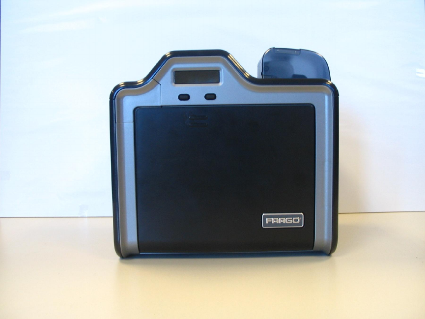
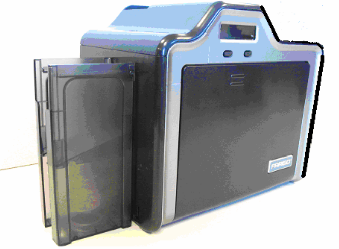
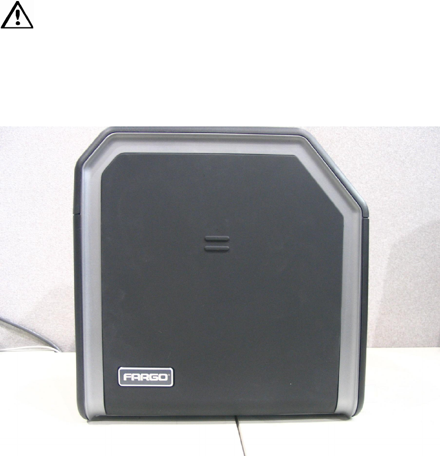
Reviewing the HDP100 (front)
RESTRICTED USE ONLY Fargo Electronics, Inc.
HDP100 High Definition Card Printer/Encoder User Guide (Rev. Beta) 4
Reviewing the HDP100 Card Printer
Display - HDP100 Printer with attached Output Hopper

RESTRICTED USE ONLY Fargo Electronics, Inc.
HDP100 High Definition Card Printer/Encoder User Guide (Rev. Beta) 5
Regulatory Compliances, Agency Listings and FCC
Rules
The purpose of this section is to provide the User with specific information on the Regulatory
Compliances, Agency Listings and FCC Rules for this Printer.
Regulatory Compliances
Term Description
CSA
(cUL)
The Printer manufacturer has been authorized by UL to represent
the Card Printer as CSA Certified under CSA Standard C22.2 No.
60950-1-03.
File Number: E145118
FCC The Card Printer complies with the requirements in Part 15 of the
FCC rules for a Class A digital device.
UL The Card Printer is listed under UL IEC 60950-1 (2001)
INFORMATION TECHNOLOGY EQUIPMENT.
File Number: E145118

RESTRICTED USE ONLY Fargo Electronics, Inc.
HDP100 High Definition Card Printer/Encoder User Guide (Rev. Beta) 6
Agency Listings
Term Description
Emissions
Standards CE, FCC, CRC c1374, EN 55022 Class A, FCC Class A, EN 55024:
1998, EN 61000-3-2 and EN 61000-3-3.
Safety Standards UL IEC 60950-1 (2001), CSA C22.2 No. 60950-1-03.
FCC Rules
This device complies with Part 15 of the FCC rules. Operation is subject to the following two
conditions:
(1) This device may not cause harmful interference.
(2) This device must accept any interference received, including interference that may cause
undesired operation.
Note: This equipment has been tested and found to comply with the limits for a Class A
digital device, pursuant to part 15 of the FCC Rules. These limits are designed to provide
reasonable protection against harmful interference when the equipment is operated in a
commercial environment. This equipment generates, uses, and can radiate radio frequency
energy and, if not installed and used in accordance with the instruction manual, may cause
harmful interference to radio communications. Operation of this equipment in a residential
area is likely to cause harmful interference in which case the user will be required to correct
the interference at his own expense.
Reference Safety Messages in this document.

RESTRICTED USE ONLY Fargo Electronics, Inc.
HDP100 High Definition Card Printer/Encoder User Guide (Rev. Beta) 7
Technical Specifications
Term Description
Accepted
Standard Card
Sizes
HDP100 and HDP100-LC (See Card tab under Printer
Adjustments):
CR-80: This selection is the default form size for the HDP100.
This will print a 3.375 in. L x 2.125 in. W (85.6mm L x 54mm W)
image including a .04 over-bleed on each of the 4 sides.
Card Size supported is 2.204 X 3.452 (56 X 87.7 mm. )
Accepted Card
Thickness .030 in. (30 mil) to .050 in. (50 mil) (.762mm to 1.270mm)
Accepted
Electronic Card
types
HID Proximity Cards, Mifare Contactless Smart Cards and Contact
Smart Cards
Accepted Card
Compositions ABS, PVC, PET and PETG
Colors Up to 16.7 million colors and 256 shades per Pixel.
Card Cartridge
Capacity HDP100 and HDP100-LC:
100 cards (.030in./.762mm)
Has refillable Card Cartridge that can either be attached to the
Printer or detached for storage. This allows single feed with the
Card Cartridge removed or with no other cards in the Card
Cartridge
Card Output
Hopper Capacity HDP100 and HDP100-LC:
250 card Output Hopper capacity (Includes Reject Hopper
capability when connected to the Flipper Module with available
storage on the Output Tray or the Lamination Module)

RESTRICTED USE ONLY Fargo Electronics, Inc.
HDP100 High Definition Card Printer/Encoder User Guide (Rev. Beta) 8
Technical Specifications (continued)
Term Description
Cardstock HDP100 and HDP100-LC:
CR100, 30 UC1 cardstock (No-Co, Lo-Co and Hi-Co)
CR100, 30 UC3 cardstock (No-Co and Hi-Co)
Dimensions HDP100: 15” H x 26.1” W x 14” D/381mm H x 663mm W x
356mmD
HDP100-LC: 15” H x 34.75” W x 14” D/381mm H x 883mm W x
356mmD
LC Module: 10 H x 13 W x 14.2D/362mm H x 330mm W x
254mmD
Display User-friendly, SmartScreen LCD Control Panel; LED display on
Card Lamination Module.
Encoding Options
(only HDP100
and HDP100-LC)
ISO Magnetic Stripe Encoding Module, dual high- and low-
coercivity, Tracks 1, 2 and 3
JIS II Magnetic Stripe Encoding Module
E-card Docking Station (required for all e-card options or 3rd
party smart card encoding)
Contact Smart Card Encoder (ISO 7816), Parts 1-4; T=0 and
T=1
Contactless Smart Card Encoder (Mifare®)
Prox Card Encoder (HID read-only) (Note: Corporate Express
1000 Cards can be used with special order Weigand/ASCII
Converter)
iCLASS™

RESTRICTED USE ONLY Fargo Electronics, Inc.
HDP100 High Definition Card Printer/Encoder User Guide (Rev. Beta) 9
Technical Specifications (continued)
Term Description
Fargo Certified
Supplies Fargo Card Printer/Encoder require highly specialized media to
function properly.
To maximize printed card quality and durability, Printhead life and
Printer/Encoder reliability, use only Fargo Certified Supplies, Fargo
warranties are void, where not prohibited by law, when non-Fargo
Certified Supplies are used.
HDP Film Options
Clear, 1,250 prints
Standard Holographic (only HDP100 and HDP100-LC)
Custom Holographic, special order (only HDP100 and HDP100-
LC)
HDP Film
Storage
Temperature
77ºF (25ºC) or lower for no longer than 1.5 years.
Humidity 20% to 80% (non-condensing)
Input Hopper
Card Capacity HDP100 and HDP100-LC:
100 cards (.030/.762mm)
Interface USB 1.1
Interfacing information for E-card Options
Maximum
Accepted Card
Width
2.125W / 54mmW
Maximum
Accepted Card
Length
(3.375L / 85.6mmL

RESTRICTED USE ONLY Fargo Electronics, Inc.
HDP100 High Definition Card Printer/Encoder User Guide (Rev. Beta) 10
Technical Specifications (continued)
Term Description
Operating
Temperature 65º F to 80º F (18º C to 27º C).
Options Printer Cleaning Kit
Ethernet Communication Port
Card Lamination Module
Output Hopper
Card Capacity HDP100/HDP100-LC
250 cards (.030mm)
Overlaminate
Options
(HDP100-LC and
HDP100 only)
All overlaminates are available in either clear, holographic globe
design or custom holographic design. They can also be optimized
for use with smart cards and Magnetic Stripes.
Here are the options:
Thermal Transfer Overlaminate, .25 mil thick, 500 prints
PolyGuard Overlaminate, .6 mil thick, 125 prints
PolyGuard Overlaminate, 1.0 mil thick, 125 prints
Power Supply 80W for HDP100
160W (two 80W bricks) for the HDP100-LC
Print Area Over-the-edge on all accepted standard card sizes.
Printing Method HDP™ Dye-Sublimation/Resin Thermal Transfer

RESTRICTED USE ONLY Fargo Electronics, Inc.
HDP100 High Definition Card Printer/Encoder User Guide (Rev. Beta) 11
Technical Specifications (continued)
Term Description
Print Ribbon
Options HDP100 and HDP100-LC (prints or images):
Full color, InTm, 1500 prints
Full color, YMC, 750 prints
Full color with resin black, YMCK, 500 prints
Full color with two resin black Panels, YMCKK, 500 prints
Full color with one resin black Panel, YMCKH, 500 prints TBD
All HDP Ribbons utilize Fargo’s exclusive RibbonTraq™ system for
maximum print quality, performance, reliability and ease of use.
Indicates the ribbon type and the number of ribbon panels printed
where Y=Yellow, M=Magenta, C=Cyan, K=Resin Black, O=Overlay,
F=Fluorescing.
Print Speed-
Batch Mode HDP100 and HDP100-LC (see note below):
85 seconds per card/42 cards per hour (YMCKK with transfer)
93 seconds per card/38 cards per hour (YMCKK/Lamination)
Print speed indicates an approximate print speed and is measured
from the time a card feeds into the Printer to the time it ejects from
the Printer.
Print speeds do not include encoding time or the time needed
for the PC to process the image.
Process time is dependent on the size of the file, the CPU,
amount of RAM and the amount of available resources at the
time of the print.

RESTRICTED USE ONLY Fargo Electronics, Inc.
HDP100 High Definition Card Printer/Encoder User Guide (Rev. Beta) 12
Technical Specifications (continued)
Term Description
Resolution 300 dpi (11.8 dots/mm)
Software Drivers Windows® 2000/XP
Supply
Frequency 50 Hz / 60 Hz
Supply Voltage 100 to 240 VAC, 3.75A (HDP100 and HDP100-LC)
100 to 240 VAC, 4.25A (HDP100 and HDP100-LC)
System
Requirements IBM-PC or compatible. Windows 2000/XP. Pentium™ class 133
MHz computer with 64 MB of RAM or higher, 200 MB free space or
higher and USB 1.1
Warranty Printer: One year; optional Extended Warranty Program (U.S.
only)
Printhead: Lifetime; unlimited pass with Fargo-certified Cards
Weight HDP100: 16 lbs.
HDP100 + Flipper Module 22 lbs.
LC Module: 36 lbs.

RESTRICTED USE ONLY Fargo Electronics, Inc.
HDP100 High Definition Card Printer/Encoder User Guide (Rev. Beta) 13
Functional Specifications
The Card Printer utilizes two different, yet closely related printing technologies to achieve its
remarkable print quality for dye-sublimation and resin thermal transfer. See previous section
as needed.
The following describes how each of these technologies works:
Function Description
Dye-
Sublimation Dye-Sublimation is the print method the Card Printer uses to produce
smooth, continuous-tone images that look photographic. (Note: This
process uses a dye-based Ribbon roll that is partitioned by a number of
consecutive color Panels.)
Process colors: The Panels are grouped in a repeating Series of
three process colors - yellow, magenta and cyan (YMC), along the
entire length of the Print Ribbon.
Panels: The Printer always prints the yellow Panel first, followed by
the magenta Panel and the cyan Panel.
Printhead: As the Print Ribbon passes beneath the Printhead,
hundreds of thermal elements within the Printhead heat the dyes on
the Ribbon. (Note: When these dyes are heated, they vaporize and
diffuse into the surface of the film and then the film is laminated onto
the card surface. A separate pass is made for each of the three color
Panels on the Ribbon.)
Color Shades: By combining the colors of each Panel and by
varying the heat used to transfer these colors, it is possible to print up
to 16.7 million different shades of color. (Note: This blends one color
smoothly into the next, producing photo-quality images with
absolutely no dot pattern.)
Dye-Diffusion Thermal Transfer: It is the process of heating a dye
suspended in a cellulous substrate until the dye can flow, diffusing
into the dye receptive surface of the card or InTM. This produces the
image in the surface of the card.

RESTRICTED USE ONLY Fargo Electronics, Inc.
HDP100 High Definition Card Printer/Encoder User Guide (Rev. Beta) 14
Printer Components: Resin Thermal Transfer to USB Interface Port
Component Description
Resin Thermal
Transfer Resin Thermal Transfer is the print method the Printer uses to print
sharp black text and crisp bar codes that can be read by both infrared
and visible-light bar code scanners.
Like dye-sublimation, this process uses the same thermal Printhead
to transfer color to a card from a resin-only Print Ribbon or the resin
black (K) Panel of a full color Print Ribbon.
The difference, however, is that solid dots of resin-based ink are
transferred and fused to the surface of the film and then the film is
laminated onto the card surface. (Note: This produces very durable,
saturated printing.)
Card Cartridge Load blank cards into this cartridge.
Card Output
Hopper Stores 250 cards.
Card
Lamination
Module
Works in conjunction with the Printer to apply a variety of different
overlaminates to printed cards, providing increased card durability
and security.
The Module has its own LED indicator light and control buttons; so it
can be operated separately from the Printer. (Note: When printing a
batch of cards, the Printer can be encoding and printing one card
while the Lamination Module laminates another card.)
LCD Display Displays the current status of the Printer.
LED Light Indicates the Printer ON, OFF, pause and error conditions.
Printhead The component of the Printer that actually does the printing. This
component is fragile and must not be bumped or touched with
anything other than a cleaning pen.
Softkey Buttons Current function is displayed above the button and will change
depending upon the Printer's mode of operation.

RESTRICTED USE ONLY Fargo Electronics, Inc.
HDP100 High Definition Card Printer/Encoder User Guide (Rev. Beta) 15
Printer Components: Resin Thermal Transfer to USB Interface Port (continued)
Component Description
Scroll Buttons Used to scroll through menus and sub-menus and to adjust certain
menu options.
Card Thickness
Adjustment
Lever
Adjusts the Printer to feed varying card thicknesses.
Card Cleaning
Roller Automatically cleans cards for higher print quality. (Note: Replace
this Roller after every 1000+ cards or as needed.)
Power Port Connect to the included power supply.
USB Interface
Port Connect to the Windows PC USB cable.

RESTRICTED USE ONLY Fargo Electronics, Inc.
HDP100 High Definition Card Printer/Encoder User Guide (Rev. Beta) 16
Printer Components: LCD and Softkey Control Pad
The Printer provides a four line, eighty (80) character LCD Displays that can communicate
helpful information about the Printer's operation.
The top three lines of the LCD Display will always be used to communicate print status,
error messages and menu options.
The bottom line of the LCD Display will always be used to communicate the current
function of the Printer's softkey buttons.
This section describes how the LCD Display and Softkey Control Pad work together.
Component Description
Softkey
Buttons The Printer has three softkey buttons that appear below the LCD
Display. Their current function is indicated by the words appearing
above them. This function will change according to the Printer's current
mode of operation.
Press the corresponding softkey button under the choice you want
to select. If no word appears above a particular button, this
indicates it has no function in that particular mode of operation. The
Printer also has another type of button on its control pad called
scroll buttons. These buttons are located just to the right of the LCD
Display.
Use these buttons to scroll through help text, to navigate through
the Printer's menus and to adjust certain Printer settings.
LCD Display The Printer's LCD Display will change according to the Printer's current
mode of operation.

RESTRICTED USE ONLY Fargo Electronics, Inc.
HDP100 High Definition Card Printer/Encoder User Guide (Rev. Beta) 17
Printer Components: LCD and Softkey Control Pad (continued)
Component Description
Ready /
Printer Open
Screens
Once the Printer has finished its system check and with the Printer
closed, the Printer will display READY to indicate that the Printer is
ready for operation. (Note: The Printer will stay in this mode until it
receives a print job or it is turned OFF.)
If the Printer is opened, the Printer Open screen will appear. Press
either the FWD or BWD buttons to move the Printer's card path
Rollers in the indicated direction.
Use the scroll buttons to select between moving the FWD or BWD
Card Rollers or the FWD or BWD Card Rollers. This is helpful when
cleaning the Printer or if clearing jammed media.
In any of these screens, the Printer will always display the Menu
option above the center softkey button.
Press this button to access the Printer's menu options. (Note: The
Menu option is available only in the Ready / Printer Open screens.)
If the Printer is equipped with the Card Lamination Module and the
Lamination Station is opened, an LCD message will appear; and
the Lamination Module's LED will flash. (Note: To move the
Lamination Module's Rollers, push the Module's Cancel or
Resume buttons.)
If both the Printer and Lamination Station are open, the LCD's FWD
or BWD softkey buttons will move ALL Rollers. In any of these
screens, the Printer will always display the MENU option above the
center softkey button. Press this button to access the Printer's
menu options. (Note: The MENU option is available only in the
READY / PRINTER OPEN screens.)

RESTRICTED USE ONLY Fargo Electronics, Inc.
HDP100 High Definition Card Printer/Encoder User Guide (Rev. Beta) 18
Printer Components: LCD and Softkey Control Pad (continued)
Component Description
Print Status
Screen During operation, the LCD will indicate the current Print Status by
showing you the area of the Printer that is active. It does this by
displaying the following icons on the second line:
FEEDING: Indicates that cards are being fed into the Printer.
FLIPPING: Indicates that the card is being transported to the
Flipper station.
ENCODING: Indicates the encode station is encoding a card
(appears only if you are using a Printer with an optional built-in
Encoding Module).
PRINTING: Indicates the Printer is printing onto the HDP film.
RECIEVING DATA: Indicates that the Printer is receiving data from
the PC.
TRANSFERRING: Indicates the Printer is transferring an image to
a blank card.
LAM: Indicates the Lamination Station is applying an overlaminate
to a card (appears only if using a Printer equipped with the optional
Card Lamination Module.
Since the Printer is capable of performing several of these functions
simultaneously, one or all of these icons may appear at once,
depending on if you are printing just one card or a batch of cards.
The Print Status screen always displays Cancel in the lower left and
Pause in the lower right.
The Cancel
button Use this button to cancel print jobs and reset the Printer for the next
print job. Cancel now has two options:
Cancel single job in memory.
Cancel all jobs in memory.
This Cancel All function will cancel all print jobs in the Printer and will
completely reset the Printer. In this case, be sure to cancel the print
jobs from the PC before pressing YES.

RESTRICTED USE ONLY Fargo Electronics, Inc.
HDP100 High Definition Card Printer/Encoder User Guide (Rev. Beta) 19
Printer Components: LCD and Softkey Control Pad (continued)
Component Description
The Pause
button Use this button to pause the Printer at any time during operation. Note
the Printer will always finish its current task before pausing.
When the Printer is paused, the LED Light will flash and the Pause
softkey button will change to Resume.
Press Resume to continue Printer operation.
The LED Light
This light works in conjunction with the Printer's LCD Display to help
communicate the Printer's current status. It is especially effective when
you are too far away from the Printer to read the LCD Display. The
following explains how to interpret both LED Lights on the exterior of
the Printer.
Off: Indicates the Printer power is OFF.
Solid GREEN: Indicates the Printer is powered ON and ready for
operation.
Flashing GREEN: Indicates a Printer ERROR or ATTENTION
condition. Refer to the Printer's LCD Display for information.

RESTRICTED USE ONLY Fargo Electronics, Inc.
HDP100 High Definition Card Printer/Encoder User Guide (Rev. Beta) 20
Printer Components: LCD and Softkey Control Pad (continued)
Component Description
Error/Attention
Screens The Printer is capable of communicating two similar yet different types
of message or prompt screens:
The first is called an ATTENTION screen. (Note: This screen appears
if an error occurs and will completely stop Printer operation. In this
case, the LCD will display ATTENTION on the first line and a brief
description of the error on the following lines.)
Press the Help button if you would like a more detailed explanation
of the error message. This will bring up the help screen explaining
the nature of the error and how to correct it. If necessary, use the
scroll buttons to scroll down the paragraph of help text.
Press Quit when you are done reading. Once the error is corrected,
resume operation or reset the Printer according to how you were
instructed in the help screen.
The second type of prompt is called a MESSAGE screen. (Note: This
screen will not stop Printer operation and serves to communicate
helpful reminders, such as if you are running low on print supplies and
also communicates any other Printer conditions of which you should be
aware. In this case, the LCD will display Message on the first line and a
brief description of the condition on the following lines.)
Like error messages, help text explaining the particular condition
can also be accessed by pressing the Help button.

RESTRICTED USE ONLY Fargo Electronics, Inc.
HDP100 High Definition Card Printer/Encoder User Guide (Rev. Beta) 21
Printer Components: Print Ribbons
The Card Printer utilizes both dye-sublimation and/or resin thermal transfer methods to print
images (print to film and transfer film to card). Since the dye-sublimation and the resin
thermal transfer print methods each provide their own unique benefits, Print Ribbons are
available in dye-sublimation-only and combination dye-sublimation/resin versions.
To make it easier to remember which Print Ribbons are which, a letter code has been
developed to indicate the type of Ribbon Panels found on each Ribbon.
This letter code is as follows:
= Dye-Sublimation Yellow Panel
= Dye-Sublimation Magenta Panel
= Dye-Sublimation Cyan Panel
= Resin Black Panel
= Heat Seal Panel

RESTRICTED USE ONLY Fargo Electronics, Inc.
HDP100 High Definition Card Printer/Encoder User Guide (Rev. Beta) 22
Printer Components: Blank Cards
Caution: Never run cards with a contaminated, dull or uneven surface through the
Printer. Printing onto such cards will ultimately lead to poor print quality. Always store the
card stock in its original packaging or in a clean, dust-free container. Do not print onto cards
that have been dropped or soiled.
Type Description
Card Size These Card Printers accept standard CR80 sized cards (3.375L x 2.125W /
85.6mmL x 54mmW) with a thickness of 30 mil to 50 mil (.030/.762mm).
Card
Design The Printer will print onto any card with a clean, level and polished PVC
surface.
Card
Surface Suitable cards must have a polished PVC surface free of fingerprints, dust
or any other types of embedded contaminants.
In addition, cards must have a completely smooth, level surface in
order for the Printer to achieve consistent color Coverage.
Some types of Proximity cards, for example, have an uneven surface
which will inhibit consistent color transfer.
Likewise, some smart card chips are raised slightly above the cards
surface, which also results in poor color transfer.
UltraCard
stock Due to the importance of using high-quality blank cards, a factory-approved
card stock called UltraCard™ is available and recommended for best
results.
UltraCard stock has a glossy PVC laminate on top and bottom and is
optically inspected to provide the cleanest, most scratch and debris-
reduced cards possible.
Two types of these cards are available: UltraCard and UltraCard III.
UltraCard stock has a PVC core and offers medium card durability.
Recommended: UltraCard III stock has a 40% polyester core and
offers high durability.
Both types of UltraCards produce printed images with a glossy, photo-
quality finish.
RESTRICTED USE ONLY Fargo Electronics, Inc.
HDP100 High Definition Card Printer/Encoder User Guide (Rev. Beta) 23
Printer Components: Card Input and Output Hoppers
Type Description
Card Cartridge The Card Cartridge is where cards are initially loaded for printing.
Your Printer's hopper provides a large door that opens widely to
make card loading simple and closes securely to help protect your
card stock.
The Printer will hold a maximum of 100 cards (based on a standard
30 mil card thickness).
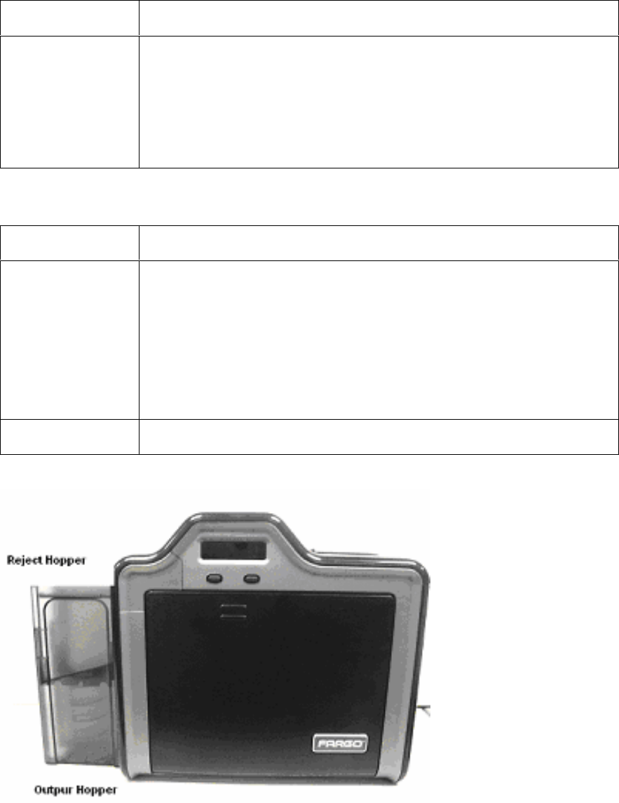
Printer Components: Card Output Hopper and Reject Hopper
Type Description
Card Output
Hopper HDP100/HDP-LC :
All standard HDP Card Printers provide a 100 card capacity Card
Output Hopper (based on a standard 30 mil card thickness). (Note:
This Hopper stores the cards after they are printed.) Shown in the
lower left.
Reject hopper functionality when connected to the Flipper Module.
The storage is available on output tray or the Lamination Module.
Reject Hopper Shown in the upper left.
RESTRICTED USE ONLY Fargo Electronics, Inc.
HDP100 High Definition Card Printer/Encoder User Guide (Rev. Beta) 24
Printer Unit: Reviewing the Card Lamination Module
Danger: The Printer’s Transfer Roller can reach temperatures exceeding 350° F
(175° C). Use extreme caution when operating the Laminator. Never touch the Transfer
Roller unless the Printer has been turned off for at least 20 to 30 minutes.
Select Printer models support the attachment of an optional Card Lamination Module. This
Module can be ordered pre-installed on your Printer from the factory or can be ordered
separately as a field upgradeable Module.
RESTRICTED USE ONLY Fargo Electronics, Inc.
HDP100 High Definition Card Printer/Encoder User Guide (Rev. Beta) 25
Printer Components: Transfer Roller
Danger: The Printer’s Transfer Roller can reach temperatures exceeding 350
degree F (175 C). Use extreme caution when operating the Transfer Roller. Never touch the
Transfer Roller unless the Printer Power has been turned off for at least 20 to 30 minutes.
Type Description
Controls Both the Printer itself and the Printer’s software Driver control the
built-in Transfer Roller.
Temperature
Adjustment To change the temperature of the Transfer Roller, adjust its
temperature through the Image Transfer within the Printer Driver
setup window.
Once adjusted, the new temperature settings will be sent down with
the next print job along with the rest of the Printer Driver information.
New
Temperature
Setting
Before printing begins, the Transfer Roller will automatically adjust
itself to the new temperature setting. (Note: This new temperature
setting will remain programmed within the Printer until it is once again
changed within the Printer Driver or until the Printer is turned OFF.)
Whenever the Printer is turned OFF, the Transfer Roller will
automatically reset itself and return to its default temperature the next
time the Printer is turned ON.
Disconnect the Printer's power supply. (Technician Note: The
Printer’s power supply serve to reset the Transfer Roller to its default
temperature. The temperature setting within the Printer Driver,
however, will stay the same until it is changed.)

RESTRICTED USE ONLY Fargo Electronics, Inc.
HDP100 High Definition Card Printer/Encoder User Guide (Rev. Beta) 26
Reviewing the Overlaminates
Important! Fargo Card Printers require highly specialized overlaminates to function
properly. To maximize Printer life, reliability, printed card quality and durability, you must use
only Fargo Certified Supplies. For this reason, the Fargo warranty is void, where not
prohibited by law, if you use non-Fargo Certified Supplies. To order additional materials,
please contact the authorized reseller.
Reviewing the Thermal Transfer Film and PolyGuard Overlaminates
Term Description Cross Reference
Thermal
Transfer Film
and
PolyGuard
Overlaminates
The Card Lamination Module will accept
either a Thermal Transfer Film overlaminate
or a Polyester Patch Overlaminate called
PolyGuard™.
Thermal Transfer Film: The Thermal
Transfer Film overlaminate is a relatively
thin material which Covers a card Edge-
to-Edge and provides a medium level of
card durability and security.)
PolyGuard Overlaminate: PolyGuard
is a much thicker material which does
not Cover Edge-to-Edge, but provides
an extremely high level of card durability
and security. (Note: PolyGuard is
available in either a 1.0 or .6 mil
thickness and should always be used for
those applications requiring the highest
degree of card durability and security.)
See the Loading the
Overlaminate.

RESTRICTED USE ONLY Fargo Electronics, Inc.
HDP100 High Definition Card Printer/Encoder User Guide (Rev. Beta) 27
Reviewing the CR-80 Patch Size
Term Description Cross Reference
CR-80 PolyGuard Overlaminate is available in a
standard CR-80 patch size. (Note: Thermal
Transfer Film overlaminate will accommodate
the CR-80 size.)
See the Loading the
Overlaminate.
Reviewing the Overlaminate Design
Term Description Cross Reference
Design Both PolyGuard and the Thermal Transfer
Film overlaminates are available in either a
clear or generic secure holographic-type
design. (Note: Custom holographic-type
overlaminates are also available with specific
designs, patterns, logos and security
features.)
Please contact the authorized reseller for
more information about custom
Overlaminates..
See the Loading the
Overlaminate.
RESTRICTED USE ONLY Fargo Electronics, Inc.
HDP100 High Definition Card Printer/Encoder User Guide (Rev. Beta) 1
Section 3: General Troubleshooting
The purpose of this section is to provide the User with specific procedures relating to the
LCD Messages, Communication Errors, Card Feeding Errors, Encoding Errors, Printing
Process Errors, Transfer Process Errors and Diagnosing the Image Problems for the
HDP100.
Important! Fargo Card Printers require highly specialized print Ribbons to function
properly. To maximize Printer life, reliability, printed card quality and durability, you must
use only Fargo Certified Supplies. For this reason, your Fargo warranty is void, where not
prohibited by law, if you use non-Fargo Certified Supplies. To order additional materials,
please contact your authorized reseller.
LCD Messages
The LCD display shows the current status of the Printer. Refer to the cause and solution
tables in this section for all possible LCD messages. (Note: These tables display the LCD
messages in alphabetical order. If the LCD message is communicating an error or requires
an action, these tables will also offer a solution to what should be done.)

RESTRICTED USE ONLY Fargo Electronics, Inc.
HDP100 High Definition Card Printer/Encoder User Guide (Rev. Beta) 2
Troubleshooting LCD Messages
LCD Message Cause Solution
Calibrating Sensor The Input Hopper cards-
out Sensor needs to be
calibrated.
Go to MENU>SETUP
PRINTER>SENSOR
CALIBRATION>CAL HOPPER
SENSOR and press SELECT.
CALIBRATE
RIBBON The print Ribbon is out of
calibration. Select CANCEL and then perform
the Ribbon calibration procedure.
See Resolving a Ribbon Sensor
Error (Ribbon Miscue) procedure.
CARD ERROR A card has been
removed; or a card is
jammed; or a Ribbon
align error has occurred
in the Print Station of the
Printer.
Clear the problem. Press
RESUME to continue. See the
Resolving the Card Jam Error
procedure.
CARD FEED
STOPPED The Ribbon access arm
was opened. This caused
the card transfer to stop.
Press RESUME or CANCEL.
CARD HOPPER
EMPTY The Card Hopper is
empty. Load more cards and press
RESUME to continue. See
Resolving a Card Hopper Empty
Error.
Card Jam A card is jammed in the
Print Station or card
flipping area of the
Printer.
See the Resolving the Card Jam
Error procedure.
Press RESUME to continue.
CARD JAM: PROX A card is jammed in the
PROX card encoding
area of the Printer.
Clear the jam. See the Resolving
the Card Jam Error procedure.
CARD JAM:
SMART A card is jammed in the
smart card encoding area
of the Printer.
Clear the jam. See Resolving a
Card Jam (Encoder) Error.
Continued on the next page

RESTRICTED USE ONLY Fargo Electronics, Inc.
HDP100 High Definition Card Printer/Encoder User Guide (Rev. Beta) 3
Troubleshooting the LCD Messages (continued)
LCD Message Cause Solution
CARD JAM:
TRANS A card is jammed in the
Transfer Station of the
Printer.
See the Resolving the Card Jam
Error procedure.
CARD NOT
FOUND The card being
processed cannot be
found.
Press RESUME to load the next
card or CANCEL. See Resolving
a Card Not Fed Error.
MULTIPLE FEED Two or more cards may
have been fed from the
Card Hopper.
If so, remove the fed cards and
verify the card thickness setting is
set to the thickness of your cards.
See Resolving a Card Not Fed
Error (Cards will not feed off the
Hopper).
Press RESUME to continue.
Clean Printer For best Printer
performance, replace the
Cleaning Cartridge Tape
and clean the Printers
Feed Rollers and
Printhead at this time.
See Cleaning.
E-Card Encoder
Startup Error A problem was detected
during Printer start-up. If this problem persists, call for
technical assistance. See E-card
Encoding Errors.
E-CARD STARTUP
ERROR A problem was detected
during Printer start-up. If this problem persists, call for
technical assistance. See E-card
Encoding Errors.
EEPROM
CORRUPT EEPROM restored with
factory default values. No action needs to be taken.
EJECTING Indicates cards are
ejecting. No action needs to be taken.
EJECTING CARD The system Firmware
has detected a card
already in the Printer and
is ejecting it.
This card has been ejected;
however, it may contain encoded
data and therefore should be
disposed of properly.
Continued on the next page

RESTRICTED USE ONLY Fargo Electronics, Inc.
HDP100 High Definition Card Printer/Encoder User Guide (Rev. Beta) 4
Troubleshooting the LCD Messages (continued)
LCD Message Cause Solution
Empty Indicates no cards or
empty. Refill.
FILM OUT The HDP Film has run
out.
OR
The HDP Film will soon
run out.
Install a new roll of film and press
RESUME to continue or CANCEL
to reset.
If this appears as an error, see
Resolving a Film Out Error.
Flipper Jam A card is jammed in the
card flipping area of the
Printer.
Clear the jam. See Flipper Jam
Error procedure.
Film Align Error Unable to align film.
OR
If this appears as a
prompt, the HDP Film
is self-aligning to the
proper position for
printing.
Check for obstruction. If the
problem persists, call for technical
assistance. If this appears as an
error, see Film Errors procedure.
Film Break/Jam
FILM LOW
FILM RELEASE
FILM RELEASE
ERROR
The HDP Film is not
installed properly or
has run out, jammed,
broken or been
damaged.
If this appears as an error, see
Film Errors or Resolving a Film
Out Error.
Film: Wrong Material The HDP Film is not
installed properly or
has run out, jammed,
broken or been
damaged.
If this appears as an error, see
Film Errors or Resolving a Film
Out Error.
Continued on the next page

RESTRICTED USE ONLY Fargo Electronics, Inc.
HDP100 High Definition Card Printer/Encoder User Guide (Rev. Beta) 5
Troubleshooting the LCD Messages (continued)
LCD Message Cause Solution
Headlift Error The Printer was unable to
raise or lower the
Printhead.
Verify that the head is not jammed.
See Resolving a Headlift Motor or
Sensor Error.
Press RESUME to retry or CANCEL
to abort. If the problem persists, call
for technical assistance.
HEAD LOADING An unrecoverable error
occurred while printing. Contact technical support if this
error repeats. Press CANCEL to
abort this card.
HEAD
RESISTANCE LCD setting for head
resistance is out of
range.
Enter a value for head resistance in
the LCD Printer Setup menu. Reset
the correct value according to the
steps in the Troubleshooting
Section. If this problem persists, call
for technical assistance.
HEAD SENSOR
ERROR The Printhead
Temperature Sensor is
not functioning or is not
connected properly.
OR
The Printhead is not
cooling properly.
If the problem persists, call for
technical assistance. See Printing
Process Errors.
HEAD VOLTAGE
ERROR A hardware fault has
prevented setting the
correct Printhead voltage.
A default value will be used. Call for
technical assistance.
H1 Indicates that the Left
Hopper is OFF. No action required.
[H1] Indicates that the Left
Hopper is ON. No action required.
H2 Indicates that the Right
Hopper is OFF. No action required.
[H2] Indicates that the Right
Hopper is ON. No action required.
Continued on the next page

RESTRICTED USE ONLY Fargo Electronics, Inc.
HDP100 High Definition Card Printer/Encoder User Guide (Rev. Beta) 6
Troubleshooting the LCD Messages (continued)
LCD Message Cause Solution
Invalid Film The Printer was unable to
sense the HDP Film
properly while printing.
OR
The Printer senses that
the wrong HDP Film had
been installed.
See Film Errors procedure.
INVALID
PASSWORD Printing disabled at this
time. Press CANCEL to abort this print
job and then check security settings
at host computer.
INVALID RIBBON The print Ribbon installed
in the Printer does not
match the Ribbon type
set in the Printer.
Get the correct Ribbon from your
dealer. See Resolving an Invalid
Ribbon Error.
Init Indicates the Printer is
beginning its startup
system check. Referred
to as initializing.
PLEASE INSERT
RIBBON Instructs the User to
properly insert the
Ribbon in the Printer.
Same as the cause.
JOB DATA ERROR
The print data sent to the
Printer is corrupt or has
been interrupted.
OR
The Feed Module is out
of sequence with the
Transfer section.
Check the interface cable and
cancel the print job from the PC.
Press CANCEL to abort this print
job and then resend the job.
See Resolving the Communication
Errors.
Continued on the next page

RESTRICTED USE ONLY Fargo Electronics, Inc.
HDP100 High Definition Card Printer/Encoder User Guide (Rev. Beta) 7
Troubleshooting the LCD Messages (continued)
LCD Message Cause Solution
Lamination A power connector must
be connected to the
Laminator module.
Insert power connector and cycle
power to the Printer. See
Resolving the Laminator (Check
Power) Error.
Lam Card Jam A card is jammed in the
Lamination module area
of the Printer.
Clear the jam. See Resolving a
Card Jam (Laminator) Error.
Press QUIT to clear this
message.
LAM CARD FLIP
ERROR A problem has been
detected in the Laminator
Flipper.
If this problem persists, call for
technical assistance. See
Resolving a Card Jam
(Laminator) Error.
LAM ERROR The Lamination module
requires attention. Check the indicated condition and
correct it, using the Laminator's
control buttons. Press QUIT to
clear this message.
See Resolving a Laminator
(General Error).
LAM HANDLER
STARTUP ERROR See the next column. If this problem persists, call for
technical assistance. See
Resolving the Laminator (Check
Power) Error.
Lam Heat Timeout The Transfer Roller was
unable to reach its goal
temperature.
Reboot the Printer and try
sending the print job again. If this
problem persists, call for technical
assistance. See Resolving LAM
Heater Times Out Error.
LAM HEATER OFF See Resolving LAM Heater Times
Out Error.
Continued on the next page

RESTRICTED USE ONLY Fargo Electronics, Inc.
HDP100 High Definition Card Printer/Encoder User Guide (Rev. Beta) 8
Troubleshooting the LCD Messages (continued)
LCD Message Cause Solution
LAM LIFT ERROR See the next column. If this problem persists, call for
technical assistance.
CHECK LAM
MATERIAL Lamination material is
low. See Resolving Check Lamination
Material Error.
LAM MEMORY
ERROR See the next column. If this problem persists, call for
technical assistance.
MAG ENCODING The magnetic stripe was
not encoded properly. See Resolving a No Magnetic
Strip Present Error.
Magnetics: The Magnetic Encoder
was properly installed. No action required.
MAG ENCODER
PAUSED The head arm assembly
has been opened during
Magnetic Encoding,
causing this operation to
halt.
Press RESUME to retry or
CANCEL to abort. See Magnetic
Encoding Errors.
MAG ENCODER
STARTUP ERROR A problem has been
detected in the MAG
encoding section of the
Printer during start-up.
If this problem persists, call for
technical assistance. See
Magnetic Encoding Errors.
Continued on the next page

RESTRICTED USE ONLY Fargo Electronics, Inc.
HDP100 High Definition Card Printer/Encoder User Guide (Rev. Beta) 9
Troubleshooting the LCD Messages (continued)
LCD Message Cause Solution
Mag Verify Error Print could not verify
MAG write.
OR
The magnetic stripe was
not encoded properly.
See Resolving a Magnetic Verify
Error.
MULTIPLE FEED Two or more cards fed
from the Card Hopper. See Resolving a Card Not Fed
Error.
No Flip Module Two sided job sent to a
one sided Printer. See a No Flipper Table Module
Error.
No Prox Encoder You are trying to send
encoding data, but the
Printer is not configured
with this Encoder type.
See Resolving a No Prox Card
Encoder Error.
Continued on the next page

RESTRICTED USE ONLY Fargo Electronics, Inc.
HDP100 High Definition Card Printer/Encoder User Guide (Rev. Beta) 10
Troubleshooting the LCD Messages (continued)
LCD Message Cause Solution
No Smart Encoder You are trying to send
encoding data, but the
Printer is not configured
with this Encoder type.
See Resolving a No Smart Card
Encoder Error.
No Mag Module MAG encoding job sent
to Printer without MAG
encoder.
You are trying to send
encoding data, but the
Printer is not configured
with this Encoder type.
See Resolving a No Magnetic
Encoder Installed Error.
No Ribbon There is no Ribbon
installed or it is broken. See Resolving a No Ribbon
Installed Error.
Ribbon Low The print Ribbon will
soon run out. If printing a large number of
cards, replace the Ribbon now or
monitor the Printer until the
Ribbon is gone and install a new
Ribbon. See Resolving a Ribbon
Out Error.
Ribbon Out The print Ribbon has run
out.
OR
There is no Ribbon or its
identification tag cannot
be read.
Install a new Ribbon and press
RESUME to continue or CANCEL
to abort. See Resolving a Ribbon
Out Error.
REINSERT
RIBBON The Ribbon must be
reinserted for proper
functioning of the Printer.
Reinsert the Ribbons or press
RESUME.
Ribbon Miscue The print Ribbon is either
damaged or the Printer is
not calibrated.
Replace the Ribbon or
recalibrate. Press RESUME to
continue or CANCEL to abort.
Continued on the next page

RESTRICTED USE ONLY Fargo Electronics, Inc.
HDP100 High Definition Card Printer/Encoder User Guide (Rev. Beta) 11
Troubleshooting the LCD Messages (continued)
LCD Message Cause Solution
Ribbon Break/Jam The print Ribbon is either
jammed or broken. If jammed, see Resolving a
Ribbon Break/Jam Error. If
broken repair by taping the
Ribbon back on to the take-up
core. Press RESUME to continue
or CANCEL to abort.
RIBBON TENSION The Ribbon tensions or
pretensions may be out
of range.
Check and adjust the LCD
settings. If this problem persists,
call for technical assistance.
Press RESUME to continue or
CANCEL to abort.
Remove Ribbon The print Ribbon is either
damaged or the Printer is
not calibrated.
Replace the Ribbon or
recalibrate. See Resolving a
Ribbon Break/Jam Error. Press
RESUME to continue or CANCEL
to abort.
Self Test Fault Self-test job could not be
initiated. Reset the Printer and try again. If
this problem persists, call for
technical assistance. See Printing
a Test Image.
Continued on the next page

RESTRICTED USE ONLY Fargo Electronics, Inc.
HDP100 High Definition Card Printer/Encoder User Guide (Rev. Beta) 12
Troubleshooting the LCD Messages (continued)
LCD Message Cause Solution
System Fault Unspecified system error
detected by the Printer
Firmware.
If this problem persists, call for
technical assistance.
Tests Self-test job cannot be
printed with the print
media installed.
Install the correct print media and
try again.
Unable to Feed The Printer is unable to
feed a card from the Card
Hopper.
Check the following then press
RESUME to continue.
Verify the card thickness
setting is set to the thickness
of your cards.
Verify the Cleaning Cartridge
is properly assembled and
fully inserted into the Printer.
Clean the in-feed rollers.
Verify your cards are within
the Printers accepted card
size range.
Be sure the cards are not
sticking together.
See Resolving an Unable to Feed
Card Error.
UNSPECIFIED
ERROR Unspecified system error
detected by the Printer
Firmware.
If this problem persists, call for
technical assistance. See
Resolving the Communication
Errors.
Continued on the next page

RESTRICTED USE ONLY Fargo Electronics, Inc.
HDP100 High Definition Card Printer/Encoder User Guide (Rev. Beta) 13
Troubleshooting the LCD Messages
LCD Message Cause Solution
UTILITY ERROR Command resulted in an
error. See Resolving the Communication
Errors.
Wrong Film The Printer was unable to
sense the HDP Film
properly while printing.
OR
The Printer senses that
the wrong HDP Film had
been installed.
If this appears as an error, see
Resolving a Film Sensor Not
Calibrated Error.
WRONG RIBBON The print Ribbon installed
in the Printer does not
match the Ribbon type
selected in the Printer
Driver.
OR
A Self-test job cannot be
printed with the print
media installed or the
Ribbon must contain
YMC panels for Sensor
calibration.
Change either accordingly. Press
RESUME to continue or CANCEL
to abort.
See Resolving a Wrong Ribbon
Error.
Ribbon Wrinkle Verify the convex Roller
(D860051) is installed
correctly with the shorter
notch towards the front of
the Printer.
Verify the density is set
within specification (67-
69).
Check to see if the Ribbon Hubs are
too tight.
Check the Printhead alignment. See
the Setting the Printhead
Resistance procedure.
Continued on the next page

RESTRICTED USE ONLY Fargo Electronics, Inc.
HDP100 High Definition Card Printer/Encoder User Guide (Rev. Beta) 14
General Troubleshooting Guide
Problem Possible Solution
Film Wrinkle Check the peel-off bar alignment with fixture TL 1733. WE DO
NOT SELL TOOLS-
Adjust the transfer tension. See the Adjusting the Transfer
Tension procedure.
Flashing Check for poor alignment of the peel-off bars, center plate or the
Transfer Roller.
Lower the transfer tension. See the Adjusting the Transfer
Tension procedure.
(Note: Flash is typically caused by excessive heat or excessive
transfer tension.)
Smudge If smudge is on the leading edge of the card, increase the
transfer tension. Verify the Take-up Motor turns without delay
when Lamination begins. If the Motor delays, increase the
transfer tension.
Adjust the transfer temperature. See the Adjusting the
Transfer Temperature procedure.
Increase the transfer dwell time. See the Adjusting the
Transfer Dwell Time and Transfer Temperature procedure.
(Note: Smudge is typically caused by low heat or low transfer
tension.)
Film Chipping /
Incomplete Transfer
of Image onto Card
Check Printhead alignment.
Lower transfer tension (if chipping is on the leading edge).
Increase the transfer temperature. See the Adjusting the
Transfer Temperature procedure.
Increase the transfer dwell time. See the Adjusting the
Transfer Dwell Time and Temperature procedure.
Continued on the next page

RESTRICTED USE ONLY Fargo Electronics, Inc.
HDP100 High Definition Card Printer/Encoder User Guide (Rev. Beta) 15
General Troubleshooting Guide (continued)
Problem Possible Solution
Ribbon Chipping /
Reverse Transfer
during Printing
Print density is set too high.
Self Test is not
square Adjust the peel off bar height with peel off bar fixture.
Adjust position of the center-plate (D860132).
Scratches Lightly buff any film contact points with a fine steel wool.
Verify the scratch is not film wrinkle. See film wrinkle in this
table.
Cards won’t feed / or
more than one is fed Verify the correct position of the card thickness lever.
Verify that the Cleaning Roller Assembly is fully seated.
Wash Check the Printhead alignment.
If washing out on resin, try changing to a different lot of film.
Printing pauses
between panels Check the air flow from the Printhead fan (D860149) to verify it
is wired correctly.
Replace Printhead cable (840143). See the Replacing the
HDP100 Series Printhead Assembly (D860004) procedure.
Card stops under
flattener and won’t
continue
Adjust the Flattener position.
Print fans run all of
the time Check for pinched Printhead wires. Replace the Printhead cable
(840143).
Replace the Printhead (220052). See the Replacing the HDP100
Series Printhead Assembly (D860004) procedure.
Lamination
Assembly sticking
open
Check the clearance of the Lamination Cover (840260-01) with
the Transfer Roller (D880146).
Check orientation of the Headlift Cam (762452).
Continued on the next page

RESTRICTED USE ONLY Fargo Electronics, Inc.
HDP100 High Definition Card Printer/Encoder User Guide (Rev. Beta) 16
General Troubleshooting Guide (continued)
Problem Possible Solution
Printhead cutting
Ribbon Verify the solder leads on the Printhead are trimmed.
Replace the Printhead cable (840143). See the Replacing the
HDP100 Series Printhead Assembly (D860004) procedure.
XX Warning: The Printhead may be extremely hot.
Transfer warming
then heater time out
after a period of time
The Transfer Roller is not connected to the Circuit Board
(A000300).
Check the crimp of the wires on the connector of the RTD
(Resistive Thermal Device) (D870168).
Transfer cooling then
heater time out after
a period of time
Replace the Lamination RTD (Resistive Thermal Device)
(D870168).
Replace the Circuit Board (A000300). See the Removing the
PCB Board Assembly (A000300) procedure.
Check the crimp of the wires on the connector of the
thermocouple (D870168).
Poor Registration See the Bad Registration Checklist.
Printer has no power Verify the Printer and Lamination unit (if applicable) are plugged
into outlet.
Verify the power cables are connected to the Circuit Board
(A000300).
Check the fuse on the Circuit Board (A000300).
Ribbon won’t queue
up Check the Ribbon orientation. Verify that you are using the
correct Ribbon type. See the Adjusting the Ribbon Type
procedure.
Use the multi-meter to check for proper Ribbon Sensor voltage.
See the Reviewing the Sensor Locations and Voltages section.
Check to see if the Ribbon drive DC Motors (D840980) are
rotating in the correct direction.
Continued on the next page

RESTRICTED USE ONLY Fargo Electronics, Inc.
HDP100 High Definition Card Printer/Encoder User Guide (Rev. Beta) 17
General Troubleshooting Guide (continued)
Problem Possible Solution
Film won’t queue up
See Film Sensor
Errors. See the
Sensor Testing
section.
Verify the Film Sensors have been calibrated.
Check to see if the Film Drive DC Motors (D840980) are rotating
in the correct direction.
Check the Film Drive Hubs (D841152-XX) and verify the Hubs
are not cracked.
Input Roller
continually spins on
power up
Verify the cable (D840687) is plugged into the Sensor (840176)
and the Circuit Board (J58).
Replace the cable (D840687). See the Removing the PCB
Board Assembly (A000300) procedure.
Card Jam during
printing 60 mil cards Check the peel off bar height with fixture.
Verify the TOF and print offset are correct.
Replace the Stepper Motor Cable (D860120).
XX Warning: The Transfer Roller may be extremely hot.
Printer will queue up
Ribbon and film but
will not print
In the diagnostic mode of the LCD, check the Platen Roller
(D860022) to verify that it is spinning clockwise when pressing
FORWARD. If the Motor is spinning counter-clockwise, replace
the Stepper Motor Cable (D860120).

RESTRICTED USE ONLY Fargo Electronics, Inc.
HDP100 High Definition Card Printer/Encoder User Guide (Rev. Beta) 18
General Troubleshooting Guide (continued)
Problem Possible Solution
Dash Lines on Image
Check the Transfer Roller (D880146) or Platen Roller (D860022)
for cuts or nicks.
Film Sensor Error Verify the Film Sensors (J35 and J36) have not been switched.
CHECK FOR ACCURACY
Verify the Take-up Motor turns without delay when Lamination
begins. Increase the transfer tension if the Motor delays.
Verify that the washers (760386) are between the e-clip and
springs on the spring loaded film and Ribbon hubs.
Verify the film is not telescoped on the roll with fixture TL1574.
Verify the Platen Roller stepper Motor cable (D860120) is wired
correctly and is connected to the Motor (E000062) and the
circuit Board (A000300) J32.
Ribbon Sticking to
the Film Increase the Ribbon Tension. See the Adjusting the Ribbon
Tension procedure.
Continued on the next page

RESTRICTED USE ONLY Fargo Electronics, Inc.
HDP100 High Definition Card Printer/Encoder User Guide (Rev. Beta) 19
Magnetic and E-card Troubleshooting Guide
Problem Possible Solution
Film is only printing
on the back half of
the card
Check to see if the Lamination Lift Motor (D840980) is rotating in
the correct direction.
Start Sentinel is
yellow or red Change the magnetic TOF in the LCD according to the start
sentinel reference chart
Verify correct mag Module placement. The mag Module should be
adjusted so that the belt (F000111) is snug prior to installing the
tensioner.
Verify correct tension of the belt (F000111). Belt should have
approximately 1/8 deflection at the center point between pulleys

RESTRICTED USE ONLY Fargo Electronics, Inc.
HDP100 High Definition Card Printer/Encoder User Guide (Rev. Beta) 20
Magnetic and E-card Troubleshooting Guide (continued)
Problem Possible Solution
Random yellow or
red readings on each
track
Verify correct tension of the belt (F000111). Belt should have
approximately 1/8 deflection at the center point between pulleys
Verify the belt (F000111) is riding in the middle of the press on
pulleys (D850190). Adjust position so the press on pulleys are
parallel / even.
Check that all wires are free from any gears
Verify Mag Voltage is @ 6 volts for Hi-Co, 3 Volts for Lo-Co and
JIS2.
Verify that the belts (F000092 and F000094) are not catching /
rubbing against the edges of the pulleys (D850221 and D840888).
Verify the belts (F000092 and F000094) are tensioned properly.
Try replacing the input stepper (E000062)
Random yellow or
red readings with a
spike in the bits
Adjust the magnetic TOF down (closer to the ideal .293) if a spike
is occurring at the end of the card.
Verify correct Magnetic Module placement. The Magnetic
Module should be adjusted so that the belt (F000111) is snug
prior to installing the tensioner.
Verify the card is not running into the Flipper Table. Check the
alignment of the Flipper Table / Flipper Offset.
Inspect all gears on the input hopper drive train for damaged
teeth
With cleaning Roller removed, verify all gears roll smoothly
and do not bind.
Check that all gears are free from wires.
Continued on the next page

RESTRICTED USE ONLY Fargo Electronics, Inc.
HDP100 High Definition Card Printer/Encoder User Guide (Rev. Beta) 21
Magnetic and E-card Troubleshooting Guide (continued)
Problem Possible Solution
Yellow or red readings
on only one track Verify wires are not pulling the Magnetic Head to one side.
Inspect the Magnetic Module to verify Magnetic Head is parallel
with Roller. If not, replace the Magnetic Module and notify
Assembly.
Magtek gives good
readings but Printer will
not verify
Check that the correct magnetic circuit Board is being used -
(A000294).
Replace the Magnetic Head (840104).
Magtek reports - LRC
parity error and track 1
or 3 has a red bar
underneath it.
The Magnetic head (840104) is assembled backwards within
the Module.
Magtek reports – First
bit is excessively close
to the edge of the card.
Card may not be
readable in the field
Check for a burr on the leading edge of the card. Scrape the
burr off with an Exacto knife.
Mag Encode Failed -
Card stops at the end
of the mag card Roller
(840234) and fails to
exit completely.
Change the Sensor Board Assembly (140407)
E – Card Mifare / Iclass
Station cannot be
found
Verify in the Encoder settings that the Mifare / IClass is listed as
installed.
Verify Mifare components are installed.
E - Card component
has no power Verify that all cables are connected properly.
Check the power @ J24 on the Circuit Board (Pin 1 +24 Volts,
Pin 2 Ground, Pin 3 +12 Volts, Pin 4 +5 Volts).
E - Card application
cannot find component Verify that the serial cable is connected to the appropriate
component and communication port
Verify the correct RS232 cable is being used

RESTRICTED USE ONLY Fargo Electronics, Inc.
HDP100 High Definition Card Printer/Encoder User Guide (Rev. Beta) 22
Communications Errors
Resolving the Communication Errors
Symptom(s): Incorrect output, communications error on PC or Printer, stalling, no
response from Printer, no job printed, “paper out” error.
Step Procedure
1 Confirm that the system meets the minimum requirements, as shown here:
IBM-PC or compatible.
Windows 98SE, Me/2000/XP Pentium™ class 233 MHz computer with
64 MB of RAM or higher
200 MB free hard disk space or higher
USB Port (Optional Ethernet connection)
2 Confirm the correct installation of the Printer Driver.
a. Close the software program and check the Printer Driver.
b. Reboot the computer.
c. Ensure the Printer Driver is installed correctly. (Note: Especially if an
obsolete Driver was recently removed.)
d. Ensure the correct setup options within the Printer Driver are selected.
e. Confirm that the Driver is current by checking at: www.fargo.com
3 Confirm the correct installation of the Flipper Table Module Assembly.
a. Reboot the computer.
b. Ensure that the Print Both Sides option in the Printer Driver is set
correctly.
c. Verify the Flipper Table Module Assembly is functioning properly by
printing out cards in a test run.
d. If you are experiencing problems, see Resolving the No Flipper Table
Module problem.

RESTRICTED USE ONLY Fargo Electronics, Inc.
HDP100 High Definition Card Printer/Encoder User Guide (Rev. Beta) 23
Resolving the Communication Errors (continued)
Step Procedure
4 Determine the problem with printing from the application.
a. Print a self-test from the Printer by holding down the Pause button on
power up to ensure that the Printer (itself) is functioning properly.
b. Print the Windows test page that is located in the General tab of the
Driver.
c. Use WordPad (a Windows 98SE, Me/2000/XP word processing
program in the Accessories Program Group).
1) Go to the File menu and select Page Setup.
2) Click on the Printer button and select the HDP600 Card Printer.
3) Click OK and reset all four margins to zero. (Note: The
WordPad will automatically replace the values with its minimum
margins.)
4) Open the program and type: “This is a Test.” then, go to File on
the menu bar and select Print.
5 Determine whether there is adequate hard Drive space.
(Note: A large volume of temporary files on the computer can cause
communications errors.)
a. Access the temporary files by following this process:
Search for all folders called TEMP. Once found, clear out the
contents of the folders.
If using Windows 98SE, Me/2000/XP, run the System Utility - Disk
Defragmenter found in the Accessories folder of the Start Menu.
Use a disk cleanup utility (such as Disk Cleanup found in the
System Tools folder of the Start menu) or use a third party
application.

RESTRICTED USE ONLY Fargo Electronics, Inc.
HDP100 High Definition Card Printer/Encoder User Guide (Rev. Beta) 24
Card Feeding Errors
All Troubleshooting procedures assume that only factory-authorized supplies are in use in
the Printer.
Resolving an Unable to Feed Card Error
Step Procedure
1 Review the following information.
Symptom: Cards will not feed at all.
Printer Error State: Card is not being detected by the Card TOF
Sensor 11 seconds after the initiation of a print job causing the Printer
to produce an error
LCD Error Display: Unable to Feed
Driver Monitor Error Display: Unable to Feed Card

RESTRICTED USE ONLY Fargo Electronics, Inc.
HDP100 High Definition Card Printer/Encoder User Guide (Rev. Beta) 25
Resolving an Unable to Feed Card Error (continued)
Step Procedure
2 Check the card quality / loading.
a. Remove cards from the Card Hopper.
b. Ensure that the cards are not sticking together by fanning them out and
then lining them back together in straight deck.
c. Press the Card Hopper Load Lever down until the Card Tray locks into
place.
d. Load up to 100 cards into the Hopper with the print side down.
e. Close the Card Hopper Cover to release the Card Tray.
f. Press on the Resume button.
g. If the cards do not feed, continue to Step 3.
3 Press the Cancel Print button on the Driver Monitor Error Display Message.
4 Reboot the Printer by cycling the power.
5 Check the Card Feed Motor.
a. Remove all cards from the Hopper.
b. Press the Card Hopper Load Lever down until the Card Tray locks into
place.
c. Using the Fargo Diagnostic utility, send a test print to the Printer. See the
Card tab (Diagnostic button) in the Printer Driver.
d. Gently touch the Card Hopper Feed Roller to verify that it is turning
e. If Roller is NOT turning, continue to Step 7.
f. If Roller is turning, continue to Step 6.

RESTRICTED USE ONLY Fargo Electronics, Inc.
HDP100 High Definition Card Printer/Encoder User Guide (Rev. Beta) 26
Resolving an Unable to Feed Card Error (continued)
Step Procedure
6 Check Hopper Tray Spring Tension.
a. Open Card Hopper Cover.
b. Using the Fargo Diagnostic utility, send a test print to the Printer. See the
Card tab (Diagnostic button) in the Printer Driver.
c. When the Card Hopper Feed Roller engages, push up on the Card
Hopper Tray.
g. If the cards feed, replace the Card Hopper Lift Spring.
d. If the cards do not feed, replace the Card Hopper Feed Roller.
7 Card Hopper Feed Roller is not turning during a print job.
a. Remove the Printer rear Cover.
b. Ensure that the Card Hopper Feed Motor power cable is securely
connected to J-20 on the Printers Main Board.
c. Ensure that the Card Hopper Feed Motor power cable is securely
connected to the Card Hopper Feed Motor.
d. Use the Fargo Diagnostic utility to send a test print to the Printer. See the
Card tab (Diagnostic button) in the Printer Driver.
e. If the Card Hopper Feed Motor is not moving, continue to Step 8.
8 Replace Card Hopper Feed Motor.
a. Replace the Card Hopper Feed Motor.
b. Use the Fargo Diagnostic utility to send a test print to the Printer. See the
Card tab (Diagnostic button) in the Printer Driver.
c. If the Card Hopper Feed Motor does not turn, replace the Main Board.
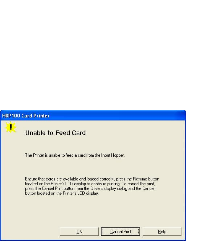
RESTRICTED USE ONLY Fargo Electronics, Inc.
HDP100 High Definition Card Printer/Encoder User Guide (Rev. Beta) 27
Resolving a Card Not Fed Error (Two (2) or more card feed at the
same time)
All Troubleshooting procedures assume that only factory-authorized supplies are in use in
the Printer.
Step Procedure
1 Review the following information.
Symptoms: Two or more cards feed at the same time causing the
cards to jam at the Card Hopper Roller. Printer is out of cards.
Printer Error State: Card is not being detected by card TOF Sensor 11
sec after the initiation of a print job causing the Printer to produce an
error
LCD Error Display: Multiple Feed
Driver Monitor Error Display: Unable to Feed Card

RESTRICTED USE ONLY Fargo Electronics, Inc.
HDP100 High Definition Card Printer/Encoder User Guide (Rev. Beta) 28
Resolving a Card Not Fed Error (Two (2) or more card feed at the same time)
Step Procedure
2 Check card quality / loading.
a. Remove cards from the Card Hopper.
b. Ensure that the cards are not sticking together by fanning them out and
then lining them back together in straight deck.
c. Press the Card Hopper Load Lever down until the Card Tray locks into
place.
d. Load up to 100 cards into the Hopper with the print side down.
e. Close the Card Hopper Cover to release the Card Tray.
f. Press on the Resume button.
g. If the cards do not feed, continue to Step 3.
3 Press the Cancel Print button on the Driver Monitor Error Display Message.
4 Reboot the Printer by cycling the power.
5 Check Card Feed TOF Sensor.
a. Remove the Printers rear Cover.
b. Use a digital volt meter to place the Positive lead to pin 9 of the J-4 Main
Board connection and the negative lead to pin 12 of the J-4 Main Board
connection.
The blocked Sensor should read +4.99 vdc.
The open Sensor should read +1.5 vdc.
c. If the Card Feed TOF Sensor does not read properly, replace the Sensor.
6 Clean the Card Feed Roller.
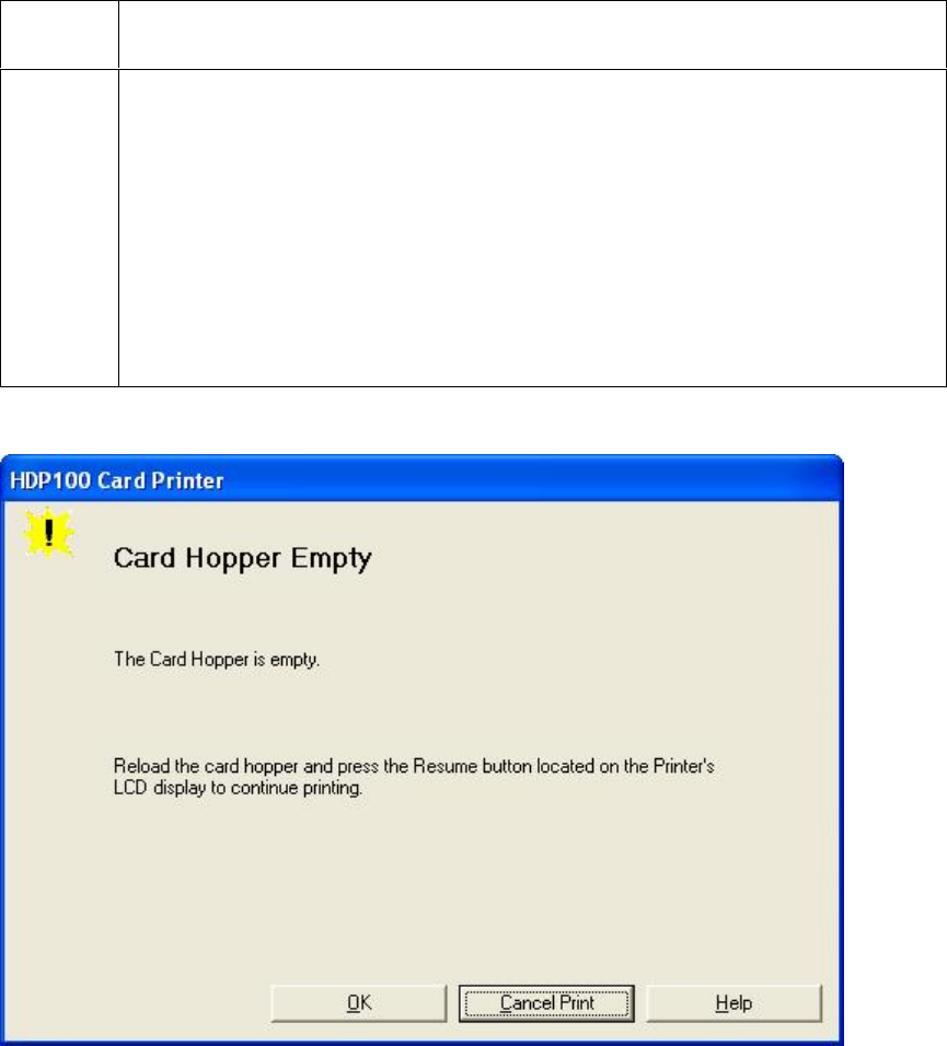
RESTRICTED USE ONLY Fargo Electronics, Inc.
HDP100 High Definition Card Printer/Encoder User Guide (Rev. Beta) 29
Resolving a Card Hopper Empty Error
Step Procedure
1 Review the following information.
Symptom: The Card Hopper is empty.
Printer Error State: Reload the Card Hopper and press the Resume
button, located on the Printer’s LCD display to continue printing.
LCD Error Display: Card Hopper Empty
Driver Monitor Error Display: Card Hopper Empty
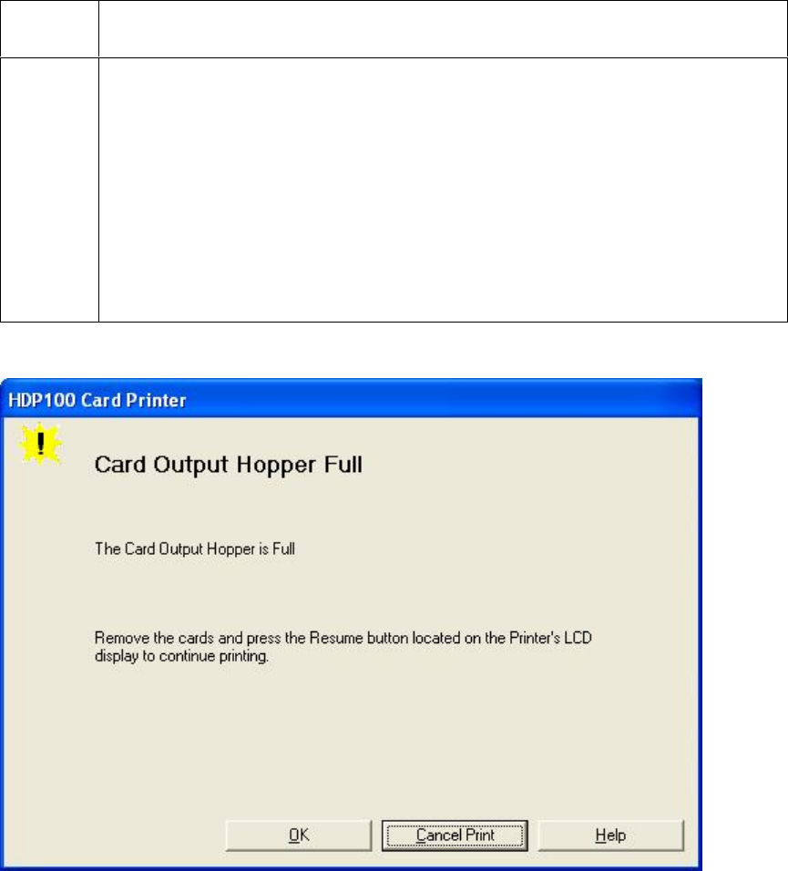
RESTRICTED USE ONLY Fargo Electronics, Inc.
HDP100 High Definition Card Printer/Encoder User Guide (Rev. Beta) 30
Resolving a Card Output Hopper Full
Step Procedure
1 Review the following information.
Symptom: The Card Output Hopper is full.
Printer Error State: Remove the cards and press the Resume button,
located on the Printer’s LCD display to continue printing.
LCD Error Display: Card Output Hopper Full
Driver Monitor Error Display: Card Output Hopper Full
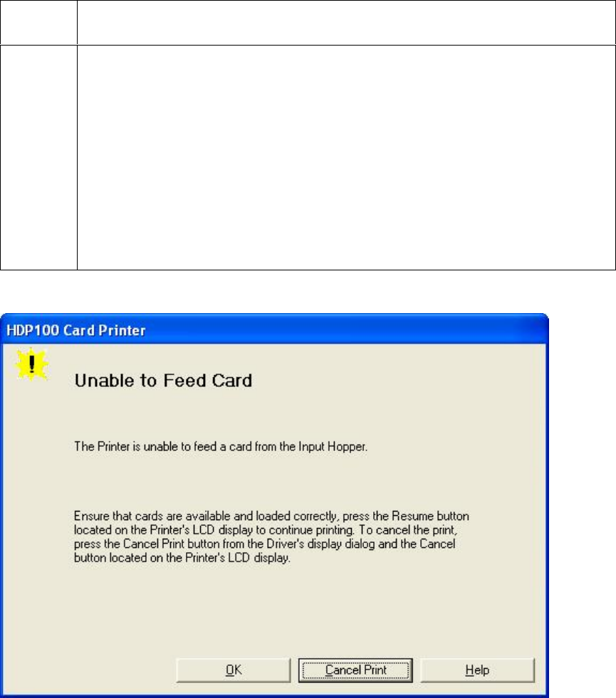
RESTRICTED USE ONLY Fargo Electronics, Inc.
HDP100 High Definition Card Printer/Encoder User Guide (Rev. Beta) 31
Resolving a Card Not Fed Error (Cards will not feed off the
Hopper)
Step Procedure
1 Review the following information.
Symptom: Cards will not feed at all.
Printer Error State: Card is not being detected by the Card TOF
Sensor 11 seconds after the initiation of a print job causing the Printer
to produce an error
LCD Error Display: Card Not Fed
Driver Monitor Error Display: Unable to Feed Card
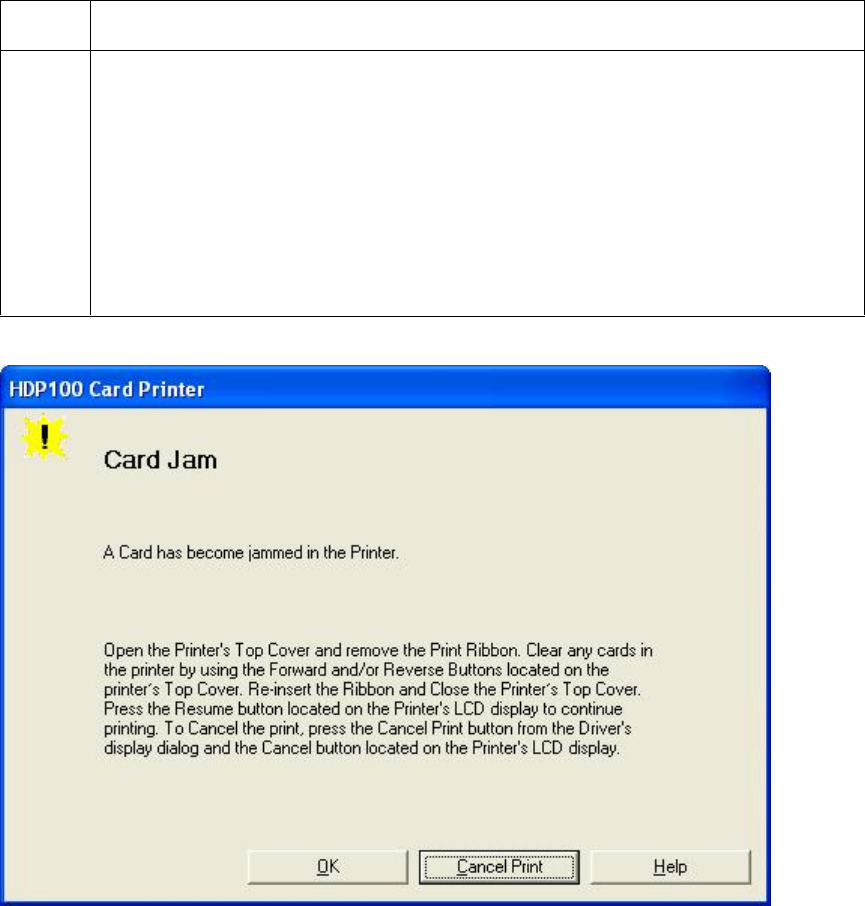
RESTRICTED USE ONLY Fargo Electronics, Inc.
HDP100 High Definition Card Printer/Encoder User Guide (Rev. Beta) 32
Resolving a Card Jam Error
All Troubleshooting procedures assume that only factory-authorized supplies are in use in
the Printer.
Step Procedure
1 Review the following information.
Symptom: Card is jammed.
Printer Error State: Card TOF Sensor is detecting no card motion.
LCD Error Display: Card Jam
Driver Monitor Error Display: Card Jam
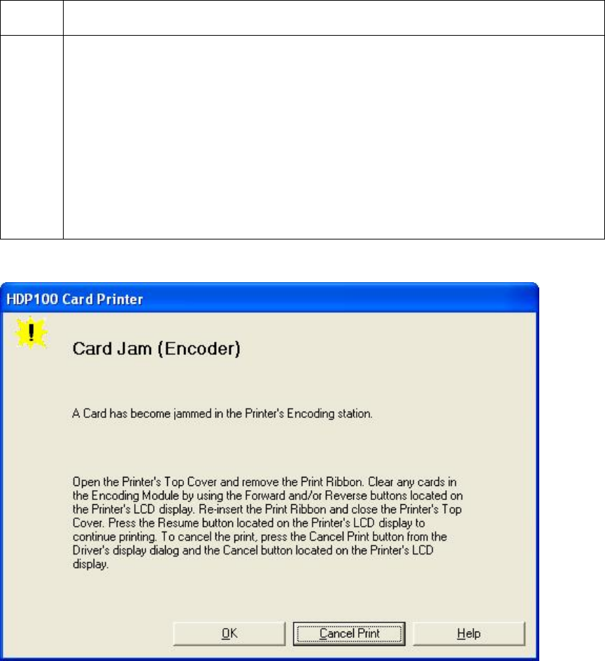
RESTRICTED USE ONLY Fargo Electronics, Inc.
HDP100 High Definition Card Printer/Encoder User Guide (Rev. Beta) 33
Resolving a Card Jam (Encoder) Error
All Troubleshooting procedures assume that only factory-authorized supplies are in use in
the Printer.
Step Procedure
1 Review the following information.
Symptom: A card has become jammed in the Printer’s Encoding station.
Printer Error State: A card has become jammed in the Printer’s
Encoding station.
LCD Error Display: Card Jam (Encoder)
Driver Monitor Error Display: Card Jam (Encoder)
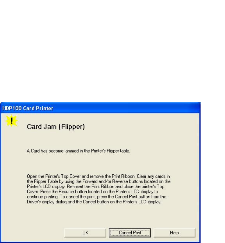
RESTRICTED USE ONLY Fargo Electronics, Inc.
HDP100 High Definition Card Printer/Encoder User Guide (Rev. Beta) 34
Resolving a Card Jam (Flipper) Error
All Troubleshooting procedures assume that only factory-authorized supplies are in use in
the Printer.
Step Procedure
1 Review the following information.
Symptom: A card has become jammed in the Printer’s Flipper Table.
Printer Error State: A card has become jammed in the Printer’s
Flipper Table.
LCD Error Display: Card Jam (Flipper)
Driver Monitor Error Display: Card Jam (Flipper)
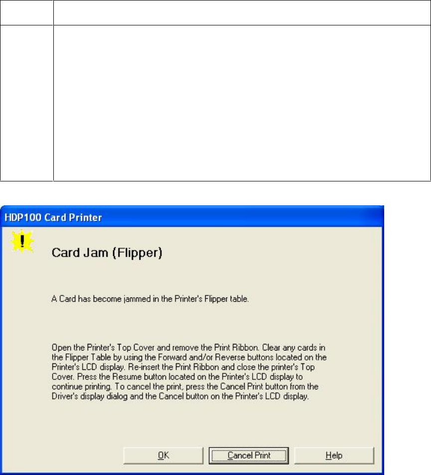
RESTRICTED USE ONLY Fargo Electronics, Inc.
HDP100 High Definition Card Printer/Encoder User Guide (Rev. Beta) 35
Resolving a Card Jam (Flipper) Error
Step Procedure
2 Open the Printer’s Flipper Table Module Cover.
a. Clear any cards in the Flipper Table Module by using the Forward
and/or Reverse buttons located on the Printer’s Top Cover.
b. Ensure that the Flipper Table Module can rotate freely.
c. Close the Printer’s Flipper Table Module.
d. Press the Resume button on the Printer’s Top Cover to continue
printing.
e. To cancel the printing, press the Cancel Print button from the Driver’s
display dialog.

RESTRICTED USE ONLY Fargo Electronics, Inc.
HDP100 High Definition Card Printer/Encoder User Guide (Rev. Beta) 36
Resolving a Card Jam (Laminator) Error
Symptom: The Card Jam: Lam Error is displayed on the LCD.
Step Procedure
1 Look for a jammed card in the Printer.
a. Open the Printer’s top Cover.
b. Remove the ribbon from the Printer.
c. Check to see if a card is jammed in the Lam Station of the Printer.
d. If a card is jammed in the Printer, use the Pause/Resume button and the
Cancel buttons to move the feed rollers and free the card. (Note: The
card can then be fed out of the Printer.)
e. If no card was found in the Lam Station, continue to Step 2.
2 Test the TOF Sensor. (Note: If the Printer has begun laminating the card
and then jams, it may be possible that the centering of the Lamination of the
card has caused the jam.)
a. Inspect the card and determine if the Lamination is centered on the card.
b. If the Lamination is hanging off the leading or trailing edge of the card,
see the Resolving the Laminator (General Error).
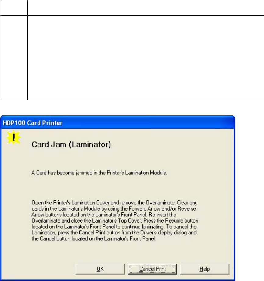
RESTRICTED USE ONLY Fargo Electronics, Inc.
HDP100 High Definition Card Printer/Encoder User Guide (Rev. Beta) 37
Resolving a Card Jam (Laminator) Error
Step Procedure
3 Test the Card Detection Sensor (D840624).
a. Remove the rear Cover.
b. Using a Digital voltmeter, connect the negative lead to ground.
c. Connect the positive lead to Pin 1 of J6.
If blocked, the voltage should read 4.9 to 5.5 VDC.
If unblocked, the Sensor should read 0.15 to 0.18 VDC.
d. If the voltages do not read correctly, replace the Sensor.
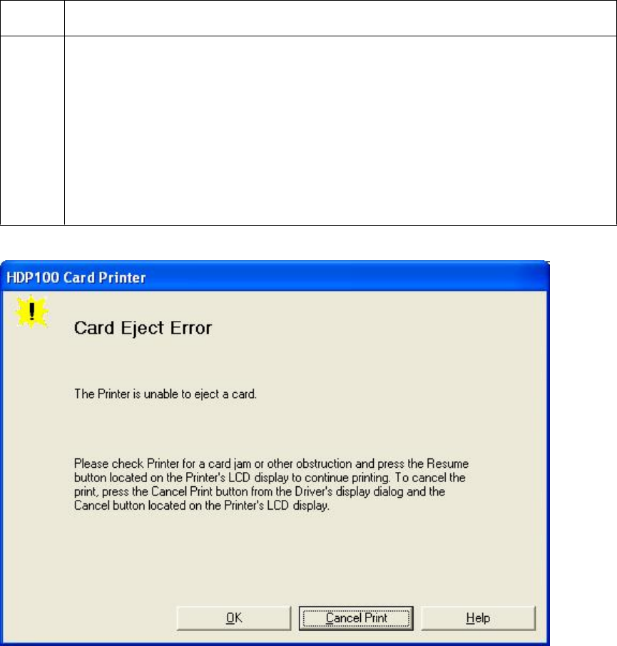
RESTRICTED USE ONLY Fargo Electronics, Inc.
HDP100 High Definition Card Printer/Encoder User Guide (Rev. Beta) 38
Resolving a Card Eject Error
All Troubleshooting procedures assume that only factory-authorized supplies are in use in
the Printer.
Step Procedure
1 Review the following information.
Symptom: The Printer is unable to eject the card.
Printer Error State: The Printer is unable to eject the card.
LCD Error Display: EJECTING CARD
Driver Monitor Error Display: Card Eject
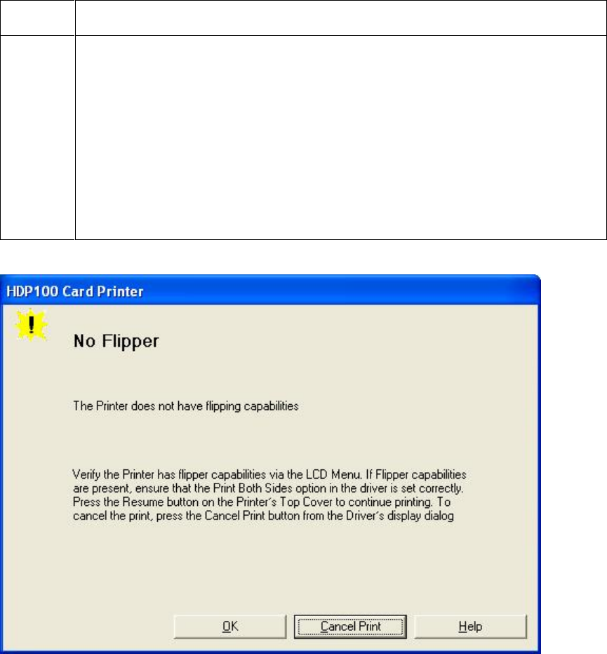
RESTRICTED USE ONLY Fargo Electronics, Inc.
HDP100 High Definition Card Printer/Encoder User Guide (Rev. Beta) 39
Resolving a No Flipper Table Module Error
All Troubleshooting procedures assume that only factory-authorized supplies are in use in
the Printer.
Step Procedure
1 Review the following information.
Symptom: The Flipper Table Module Assembly is not functioning.
Printer Error State: The Printer is unable to communicate with the
Flipper Module.
LCD Error Display: No Flip Module
Driver Monitor Error Display: No Flipper
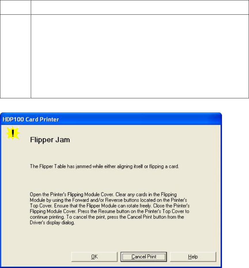
RESTRICTED USE ONLY Fargo Electronics, Inc.
HDP100 High Definition Card Printer/Encoder User Guide (Rev. Beta) 40
Resolving a Flipper Jam Error
All Troubleshooting procedures assume that only factory-authorized supplies are in use in
the Printer.
Step Procedure
1 Review the following information.
Symptom: The Flipper Table Module is jamming.
Printer Error State: The Flipper Table has jammed while either
aligning itself or flipping a card.
LCD Error Display: Flipper Jam
Driver Monitor Error Display: Flipper Jam
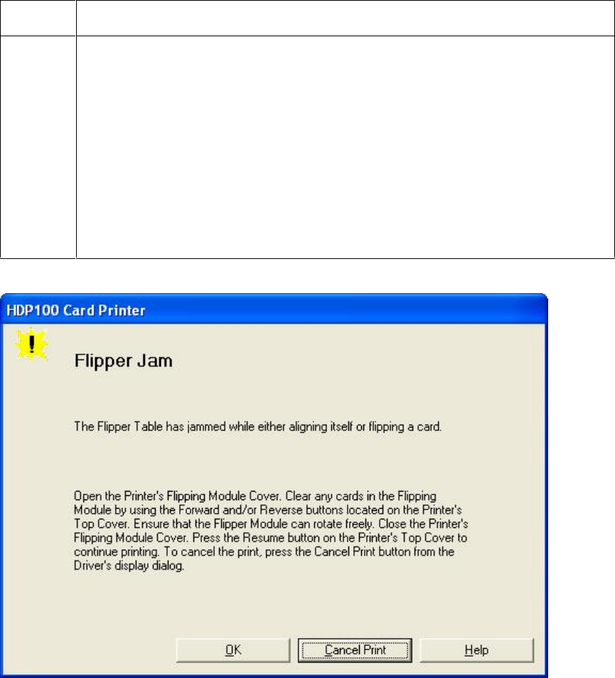
RESTRICTED USE ONLY Fargo Electronics, Inc.
HDP100 High Definition Card Printer/Encoder User Guide (Rev. Beta) 41
Resolving a Flipper Jam Error
Step Procedure
2 Open the Printer’s Flipper Table Module Cover.
a. Clear any cards in the Flipper Table Module by using the Forward
and/or Reverse buttons located on the Printer’s Top Cover.
b. Ensure that the Flipper Table Module can rotate freely.
c. Close the Printer’s Flipper Table Module.
d. Press the Resume button on the Printer’s Top Cover to continue
printing.
e. To cancel the printing, press the Cancel Print button from the Driver’s
display dialog.
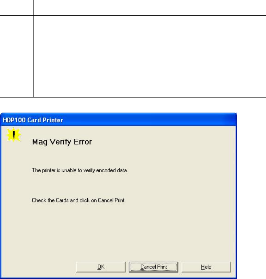
RESTRICTED USE ONLY Fargo Electronics, Inc.
HDP100 High Definition Card Printer/Encoder User Guide (Rev. Beta) 42
Magnetic Encoding Errors
Resolving a Magnetic Verify Error
All Troubleshooting procedures assume that only factory-authorized supplies are in use in
the Printer.
Step Procedure
1 Review the following information.
Symptom: The Printer is unable to verify encoded data.
Printer Error State: The Printer is unable to verify encoded data.
LCD Error Display: Mag Verify Error
Driver Monitor Error Display: Magnetic Verify

RESTRICTED USE ONLY Fargo Electronics, Inc.
HDP100 High Definition Card Printer/Encoder User Guide (Rev. Beta) 43
Resolving a Magnetic Verify Error (continued)
Step Procedure
2 Check to ensure that the cards are loaded properly, as follows:
The Magnetic Stripe should be down and away from the front.
Or
If facing the Hopper, the Magnetic Stripe should be down and to the right
side.
3 a. Press on the Resume button.
b. If the error continues, go to step 4.
4 Verify the Driver settings if cards are loaded properly. See the Using the
Magnetic Encoding tab (HDP600) procedure.
5 Verify that data is being encoded to the Magnetic Stripe.
a. Clear any Error Messages from the LCD by unplugging the Printer and
reapplying power.
b. Remove the failed card.
c. Use a Magnetic Stripe reader or magnetic developer spray to determine
if data is being written to the Magnetic Stripe.
d. If data is not being written to the Magnetic Stripe,
Open the front Cover.
Remove the Magnetic Module Cover screw.
Remove the Magnetic Module Cover.
Verify that the Magnetic Module is seated securely into the
Magnetic Module docking station.
e. If the Magnetic Module is properly seated, replace the magnetic head
(as needed). (Note: See the current HDP600 Service Manual for
related instructions in the Parts Replacement Section.)
f. If data is being written to the Magnetic Stripe, the Magnetic Offset may
need to be adjusted. See the Setting the Magnetic TOF procedure.
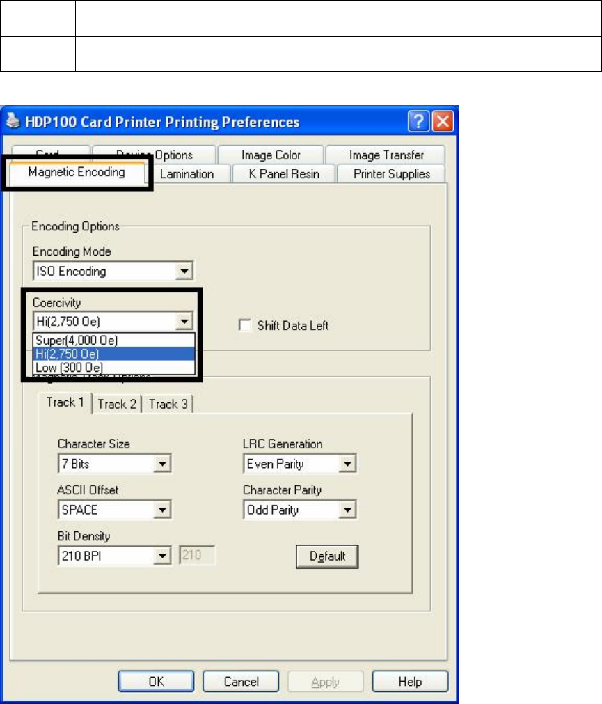
RESTRICTED USE ONLY Fargo Electronics, Inc.
HDP100 High Definition Card Printer/Encoder User Guide (Rev. Beta) 44
Resolving a Magnetic Verify Error
Step Procedure
6 Verify that the coercivity of the cards matches the Driver Settings.
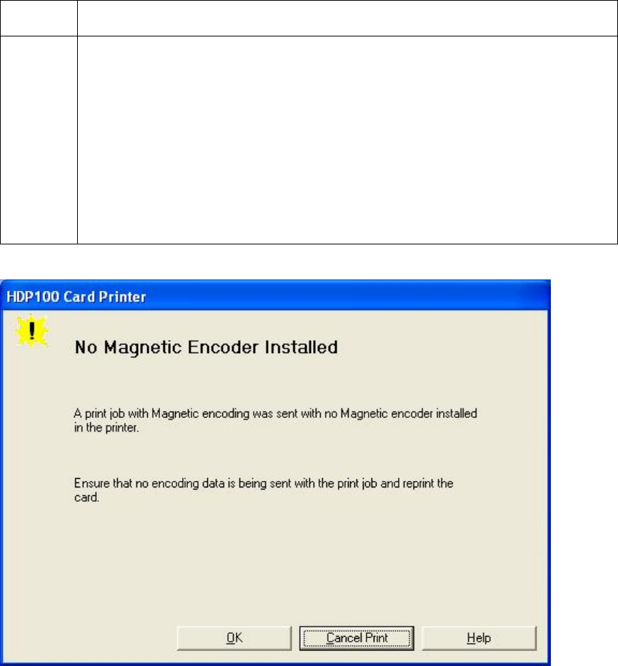
RESTRICTED USE ONLY Fargo Electronics, Inc.
HDP100 High Definition Card Printer/Encoder User Guide (Rev. Beta) 45
Resolving a No Magnetic Encoder Installed Error
All Troubleshooting procedures assume that only factory-authorized supplies are in use in
the Printer.
Step Procedure
1 Review the following information.
Symptom: There is no Magnetic Encoder installed.
Printer Error State: A print job with Magnetic encoding was sent with
no Magnetic encoder installed in the Printer.
LCD Error Display: No Mag Module
Driver Monitor Error Display: No Magnetic Encoder Installed

RESTRICTED USE ONLY Fargo Electronics, Inc.
HDP100 High Definition Card Printer/Encoder User Guide (Rev. Beta) 46
Resolving a No Magnetic Encoder Installed Error
Step Procedure
2 Press the Cancel Print button on the Driver Monitor Error Display
Message.
3 Reboot the Printer by cycling the power.
4 Verify that the Printer has a Magnetic Encoder installed.
a. Open the front Cover.
b. Remove the Magnetic Module Cover screw.
c. Remove the Magnetic Module Cover.
d. Verify that the Printer has a Magnetic Module installed. (Note: If the
Printer is equipped with a Magnetic Encoder Module, ensure that it is
seated securely into the Magnetic Module docking station. If the issue
persists, replace the Magnetic Module. See the HDP600 service
manual for replacement procedures.)
5 If the Printer has no Magnetic Encoder Module, verify that the encoding
data was sent in error, check the appropriate software user’s manual for
encoding instructions.

RESTRICTED USE ONLY Fargo Electronics, Inc.
HDP100 High Definition Card Printer/Encoder User Guide (Rev. Beta) 47
Resolving a No Magnetic Strip Present Error
All Troubleshooting procedures assume that only factory-authorized supplies are in use in
the Printer.
Step Procedure
1 Review the following information.
Symptom: There is no Magnetic Strip present.
Printer Error State: The Printer is unable to find a Magnetic stripe on
the card.
LCD Error Display: No Magnetic Strip Present
Driver Monitor Error Display: No Magnetic Strip Present
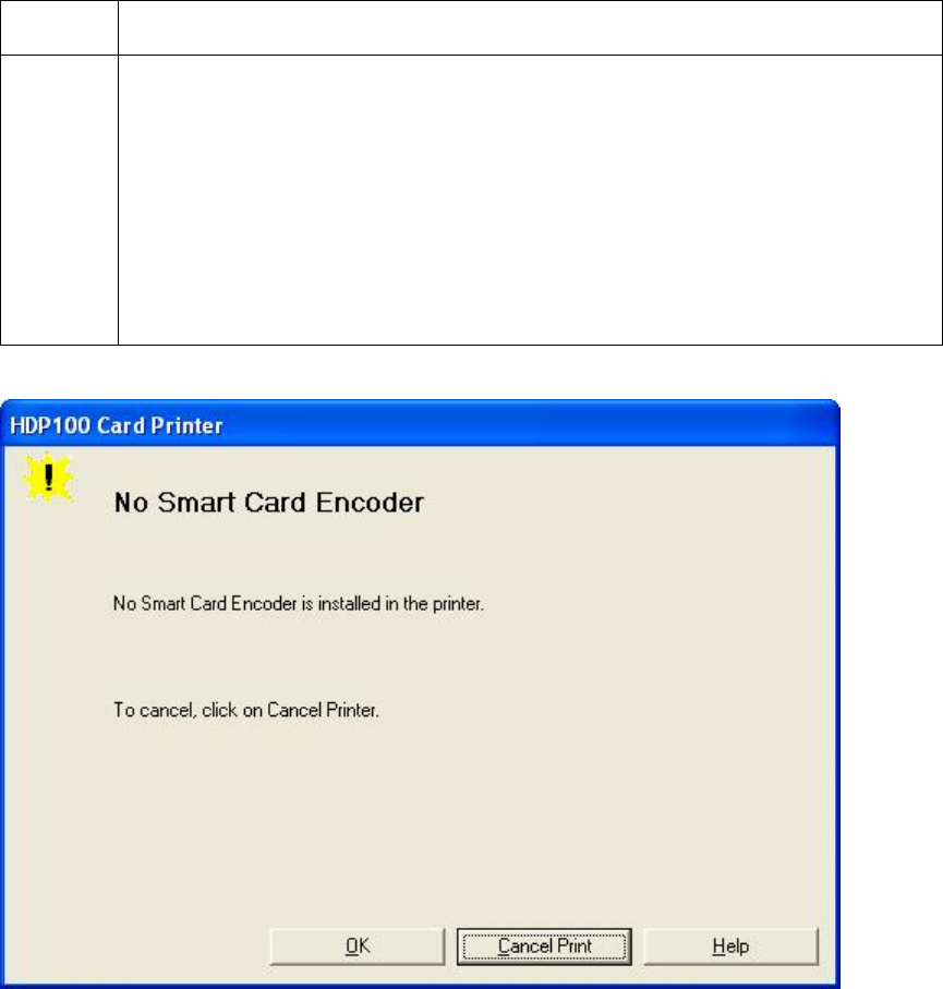
RESTRICTED USE ONLY Fargo Electronics, Inc.
HDP100 High Definition Card Printer/Encoder User Guide (Rev. Beta) 48
E-card Encoding Errors
Resolving a No Smart Card Encoder Error
All Troubleshooting procedures assume that only factory-authorized supplies are in use in
the Printer.
Step Procedure
1 Review the following information.
Symptom: There is no Smart Card Encoder installed.
Printer Error State: No Smart Card Encoder is installed in the Printer.
LCD Error Display: No Smart Encoder
Driver Monitor Error Display: No Smart Card Encoder
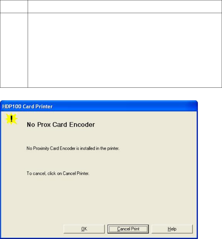
RESTRICTED USE ONLY Fargo Electronics, Inc.
HDP100 High Definition Card Printer/Encoder User Guide (Rev. Beta) 49
Resolving a No Prox Card Encoder Error
All Troubleshooting procedures assume that only factory-authorized supplies are in use in
the Printer.
Step Procedure
1 Review the following information.
Symptom: There is no Prox Card Encoder installed.
Printer Error State: Not Proximity Card Encoder is installed in the
Printer.
LCD Error Display: No Prox Encoder
Driver Monitor Error Display: No Prox Card Encoder
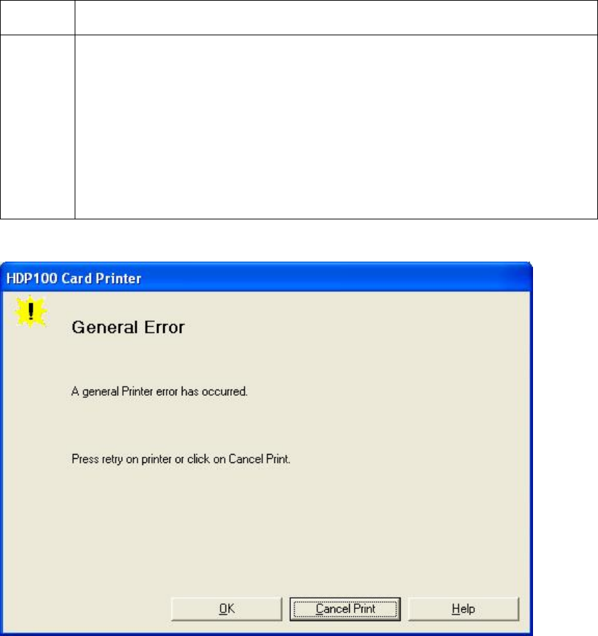
RESTRICTED USE ONLY Fargo Electronics, Inc.
HDP100 High Definition Card Printer/Encoder User Guide (Rev. Beta) 50
Film Errors
Resolving a Film Not Installed Error
All Troubleshooting procedures assume that only factory-authorized supplies are in use in
the Printer.
Step Procedure
1 Review the following information.
Symptom: The Transfer Film is not installed.
Printer Error State: The Transfer Film is not installed.
LCD Error Display: No Film
Driver Monitor Error Display: Transfer Film Not Installed
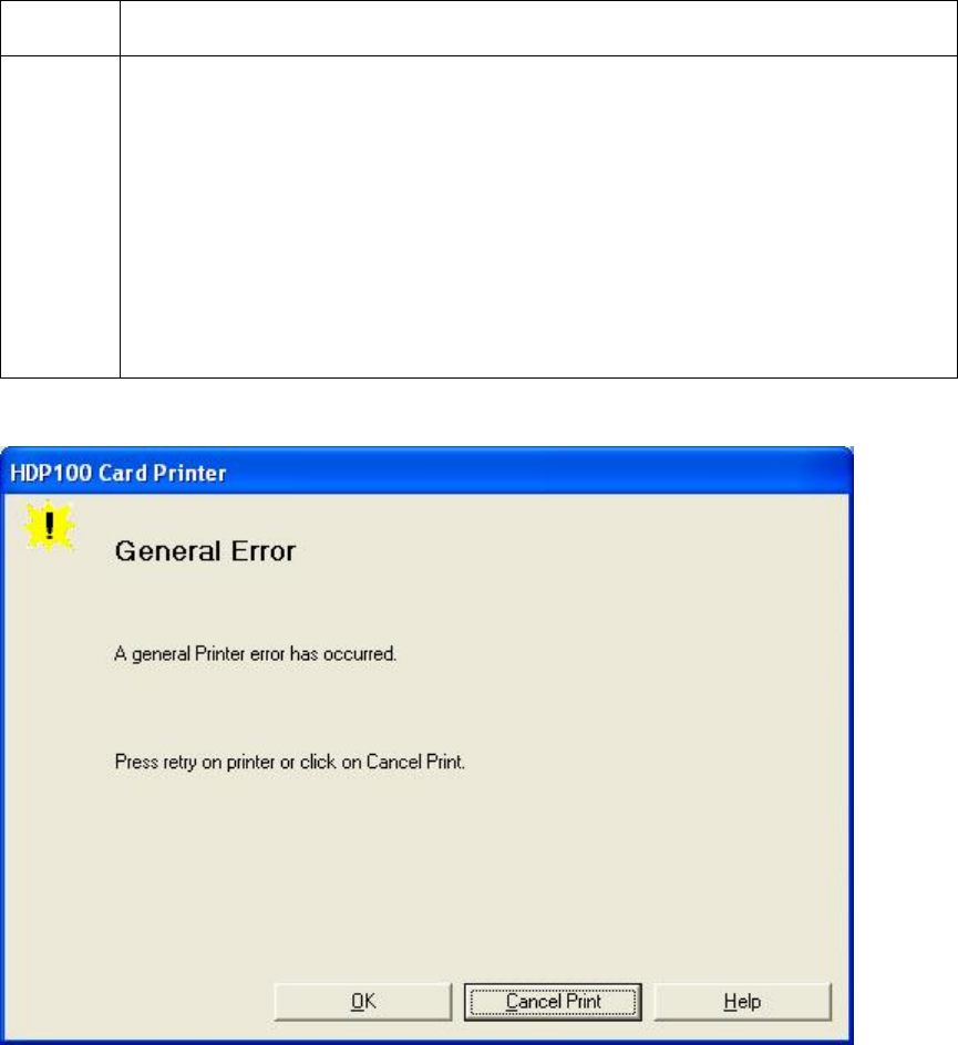
RESTRICTED USE ONLY Fargo Electronics, Inc.
HDP100 High Definition Card Printer/Encoder User Guide (Rev. Beta) 51
Resolving a Film Sensor Not Calibrated Error
All Troubleshooting procedures assume that only factory-authorized supplies are in use in
the Printer.
Step Procedure
1 Review the following information.
Symptom: The Transfer Film Sensors are not calibrated.
Printer Error State: The Transfer Film Sensors must be calibrated
before the transfer film will align properly.
LCD Error Display: Transfer Film Sensor Not Calibrated
Driver Monitor Error Display: Transfer Film Sensor Not Calibrated
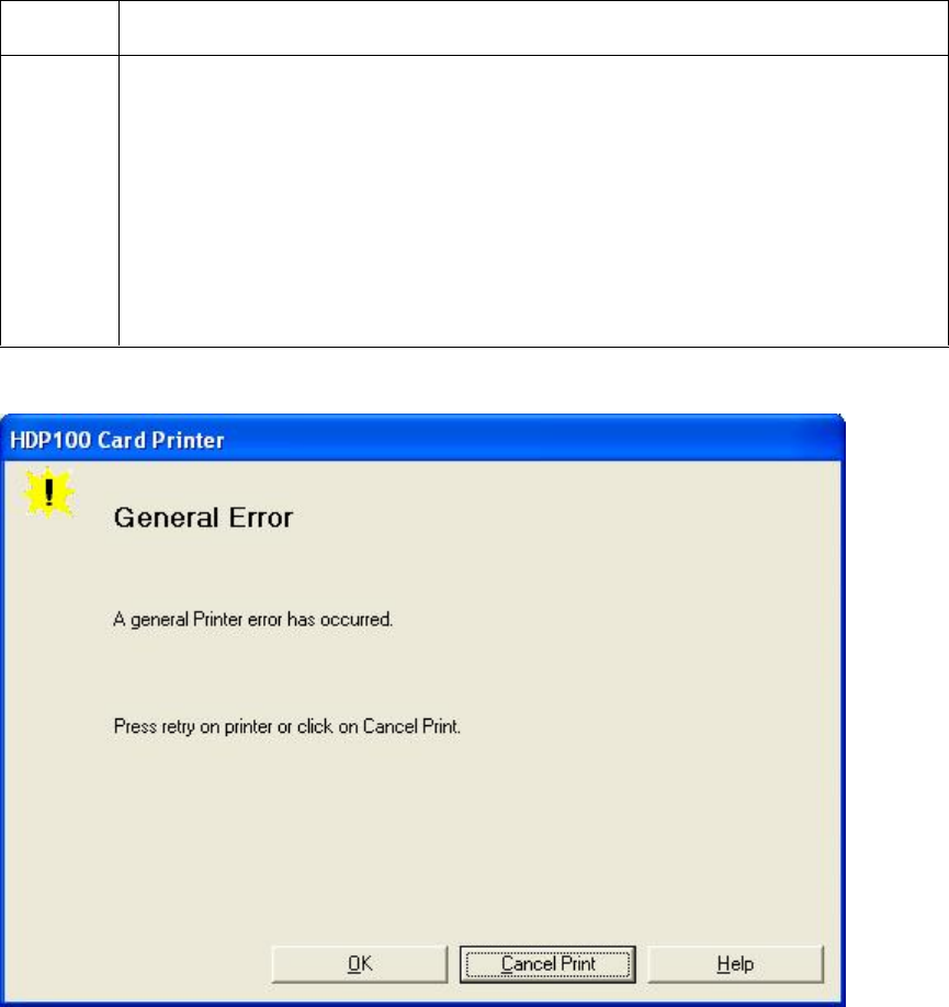
RESTRICTED USE ONLY Fargo Electronics, Inc.
HDP100 High Definition Card Printer/Encoder User Guide (Rev. Beta) 52
Resolving a Film Out Error
All Troubleshooting procedures assume that only factory-authorized supplies are in use in
the Printer.
Step Procedure
1 Review the following information.
Symptom: The Transfer Film has run out.
Printer Error State: The Transfer Film has run out.
LCD Error Display: Film Out
Driver Monitor Error Display: Transfer Film Out

RESTRICTED USE ONLY Fargo Electronics, Inc.
HDP100 High Definition Card Printer/Encoder User Guide (Rev. Beta) 53
Printing Process Errors
Resolving a Ribbon Sensor Error (Ribbon Miscue)
All Troubleshooting procedures assume that only factory-authorized supplies are in use in
the Printer.
Step Procedure
1 Review the following information.
Symptom: The Printer rolls through Ribbon and errors out
Printer Error State: The Printer cannot find the next panel on the
Ribbon.
LCD Error Display: Ribbon Miscue
Driver Monitor Error Display: Ribbon Sensor

RESTRICTED USE ONLY Fargo Electronics, Inc.
HDP100 High Definition Card Printer/Encoder User Guide (Rev. Beta) 54
Resolving a Ribbon Sensor Error (Ribbon Miscue)
Step Procedure
2 Open the front Cover and remove the Ribbon.
a. Check that the Ribbon is in good condition and not wrinkled or broken.
b. If Ribbon is broke or wrinkled, repair the Ribbon and wind up the take-
up roll 4-color panels past the damaged area.
3 Press on the Resume button.
If the issue persists, continue to Step 4.
4 Replace the Ribbon.
a. Press on the Resume button.
b. If the issue persists, continue to Step 5.
5 Press the Cancel Print button on the Driver Monitor Error Display
Message.
6 Reboot the Printer by cycling the power.
7 Using the driver calibration tab calibrate the Ribbon Sensor.
If the issue persists, continue to Step 8.
8 Replace the Ribbon Sensor.
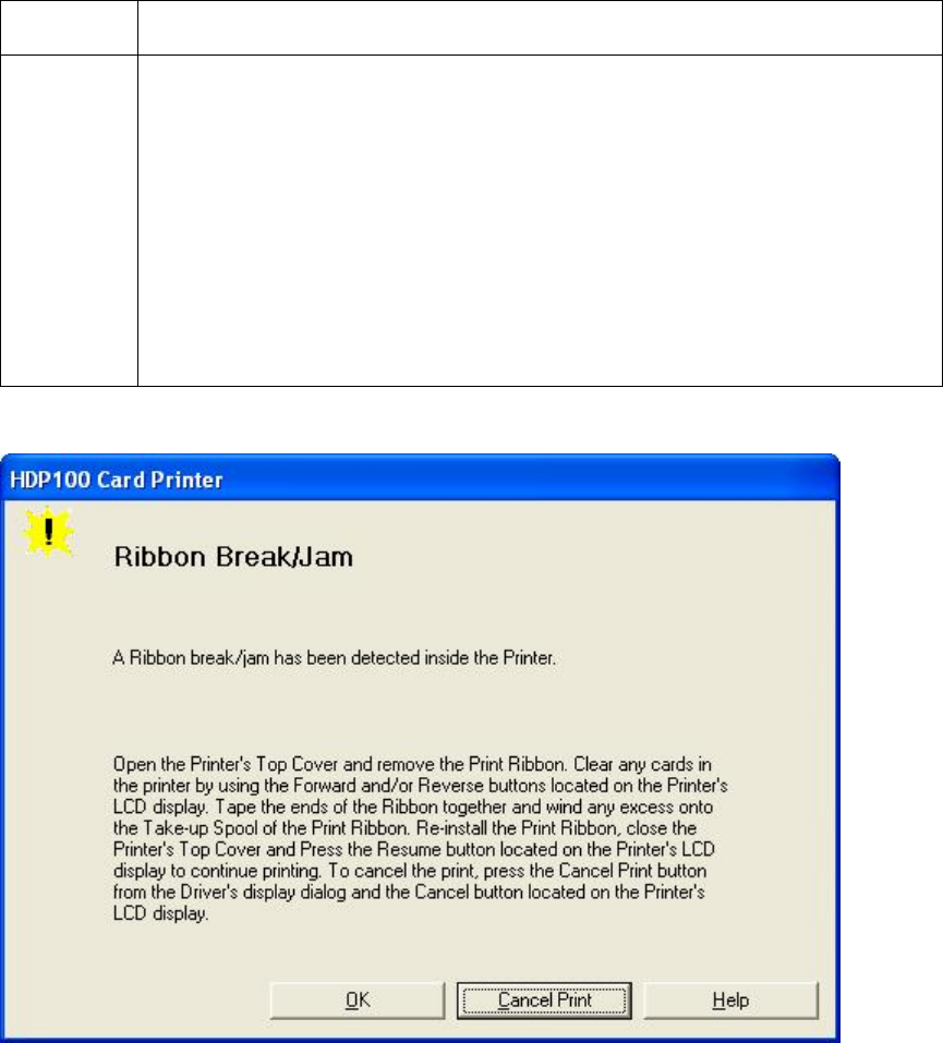
RESTRICTED USE ONLY Fargo Electronics, Inc.
HDP100 High Definition Card Printer/Encoder User Guide (Rev. Beta) 55
Resolving a Ribbon Break/Jam Error
All Troubleshooting procedures assume that only factory-authorized supplies are in use in
the Printer.
Step Procedure
1 Review the following information.
Symptom: The Print Ribbon has become jammed or has broken in
the Printer
Printer Error State: The Ribbon Supply Encoder Sensor has
unexpectedly stop receiving information from the Ribbon Encoder
LCD Error Display: Ribbon Break/Jam
Driver Monitor Error Display: Ribbon Break/Jam

RESTRICTED USE ONLY Fargo Electronics, Inc.
HDP100 High Definition Card Printer/Encoder User Guide (Rev. Beta) 56
Resolving a Ribbon Break/Jam Error (continued)
Step Procedure
2 Open the front Cover and remove the Ribbon.
If Ribbon is broken, continue to Step 3.
If Ribbon is in good condition, continue to Step 6.
3 Adjust the print offset. See the Aligning the Print Offset procedure.
If the issue persists, continue to Step 4.
4 Repair the Ribbon and wind up the take-up roll 4 color panels past the
damage area.
a. Press on the Resume button.
b. If the issue persists, continue to Step 5.
5 Use the Fargo Diagnostic utility to cycle the Printhead to ensure proper
printhead operation. See the Card tab (Diagnostic button) in the Printer
Driver.
If the Printhead does not cycle properly, see Resolving the Headlift
Motor / Sensor Error.
If the Printhead functions properly, continue to Step 6.
6 Replace the Ribbon.
a. Press on the Resume button.
b. If the issue persists, continue to Step 7.
7 Remove the rear Cover in order to check that the Ribbon Encoder Sensor
is securely connected to the J-4 Main Board connection and to the Encoder
Sensor.
a. Press on the Resume button.
b. If the issue persists, replace the Encoder Sensor.
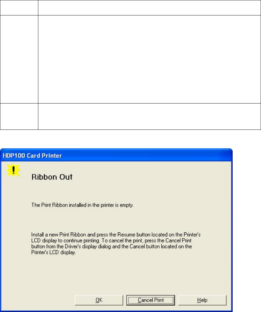
RESTRICTED USE ONLY Fargo Electronics, Inc.
HDP100 High Definition Card Printer/Encoder User Guide (Rev. Beta) 57
Resolving a Ribbon Out Error
All Troubleshooting procedures assume that only factory-authorized supplies are in use in
the Printer.
Step Procedure
1 Review the following information.
Symptom: Printer will not print.
Printer Error State: The Ribbon Sensor has detected the End Of
Ribbon mark
LCD Error Display: Ribbon Out
Driver Monitor Error Display: Ribbon Out
2 Replace the Ribbon
a. Press on the Resume button.
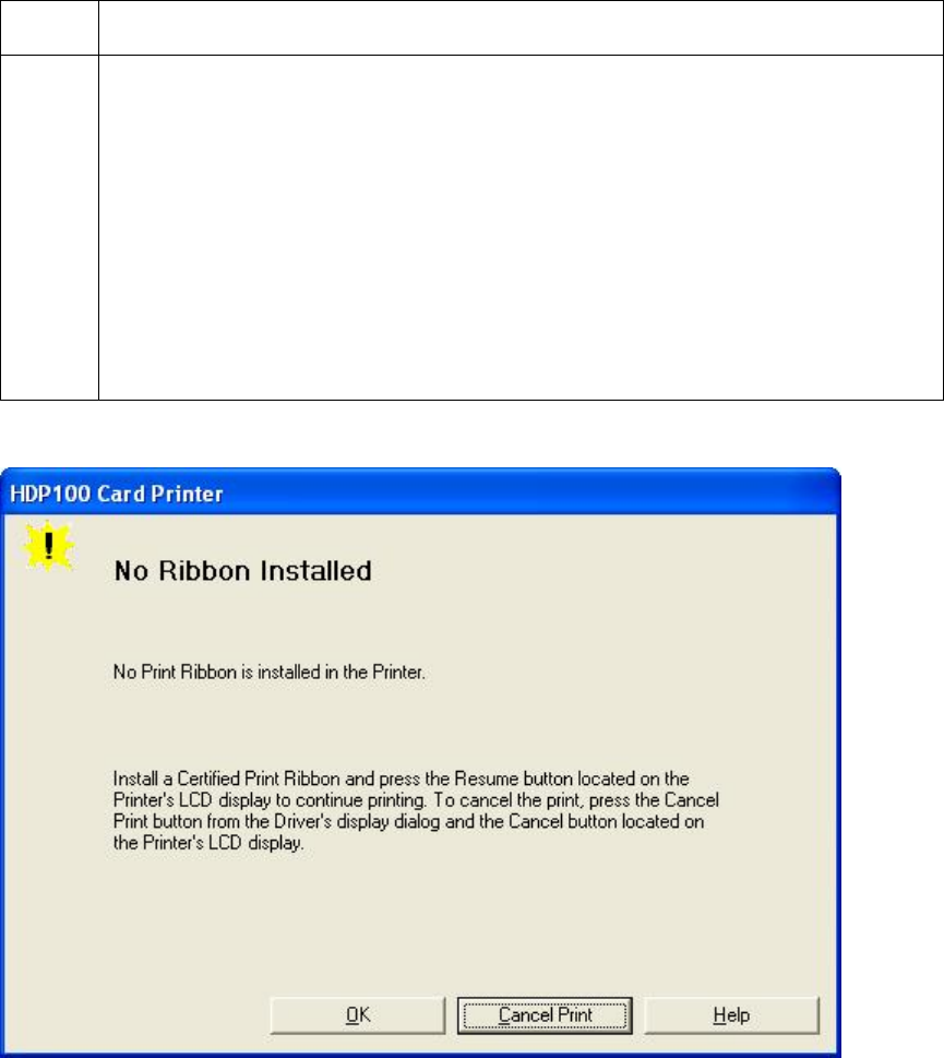
RESTRICTED USE ONLY Fargo Electronics, Inc.
HDP100 High Definition Card Printer/Encoder User Guide (Rev. Beta) 58
Resolving a No Ribbon Installed Error
All Troubleshooting procedures assume that only factory-authorized supplies are in use in
the Printer.
Step Procedure
1 Review the following information.
Symptom: The Printer errors are out as soon as it receives data from
PC
Printer Error State: The Printer RFID Sensor is not receiving a signal
from the Ribbon
LCD Error Display: No Ribbon
Driver Monitor Error Display: No Ribbon Installed

RESTRICTED USE ONLY Fargo Electronics, Inc.
HDP100 High Definition Card Printer/Encoder User Guide (Rev. Beta) 59
Resolving a No Ribbon Installed Error
Step Procedure
2 Verify that a Ribbon is installed in the Printer.
a. Press on the Resume button.
b. If the issue persist, continue to Step 3.
3 Remove the rear Cover and check that the Ribbon RFID cable is securely
connected to the Main Board (J-5) and the RFID Sensor.
If the connections are loose, reattach them.
Press on the Resume button.
If the connections are good or if the issue persists, continue to Step 4.
4 Replace the Ribbon RFID Sensor.
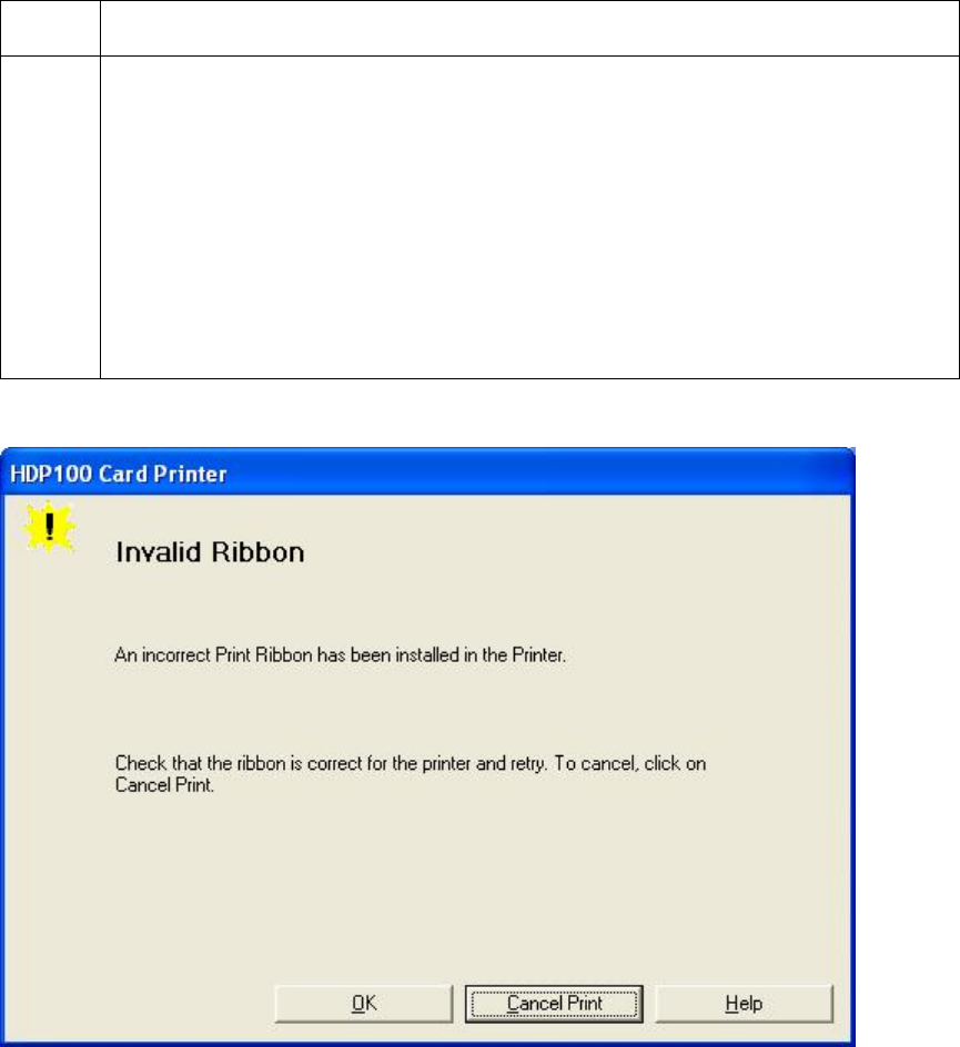
RESTRICTED USE ONLY Fargo Electronics, Inc.
HDP100 High Definition Card Printer/Encoder User Guide (Rev. Beta) 60
Resolving a Invalid Ribbon Error
All Troubleshooting procedures assume that only factory-authorized supplies are in use in
the Printer.
Step Procedure
1 Review the following information.
Symptom: Printer errors out as soon as it receives data from the PC
Printer Error State: The Ribbon installed does not match the Printer
model.
LCD Error Display: Invalid Ribbon
Driver Monitor Error Display: Invalid Ribbon

RESTRICTED USE ONLY Fargo Electronics, Inc.
HDP100 High Definition Card Printer/Encoder User Guide (Rev. Beta) 61
Resolving a Invalid Ribbon Error
Step Procedure
2 Verify that the Ribbon installed is designed for the correct Printer model.
3 Press on the Resume button.
If the issue persists, continue to Step 4.
4 Remove the rear Cover and check that the Ribbon RFID cable is securely
connected to the Main Board (J-5) and the RFID Sensor.
If the connections are loose, reattach
Press on the Resume button.
If the connections are good or if the issue persists, continue to Step 5.
5 Replace the Ribbon RFID Sensor.
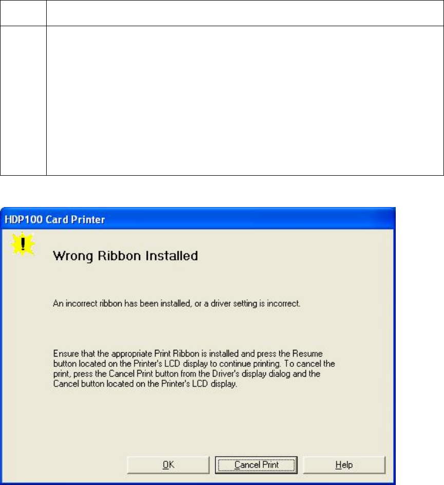
RESTRICTED USE ONLY Fargo Electronics, Inc.
HDP100 High Definition Card Printer/Encoder User Guide (Rev. Beta) 62
Resolving a Wrong Ribbon Error
All Troubleshooting procedures assume that only factory-authorized supplies are in use in
the Printer.
Step Procedure
1 Review the following information.
Symptom: Printer errors out as soon as it receives data from the PC
Printer Error State: The Ribbon installed does not match the Printer
Driver information
LCD Error Display: Wrong Ribbon
Driver Monitor Error Display: Invalid Ribbon

RESTRICTED USE ONLY Fargo Electronics, Inc.
HDP100 High Definition Card Printer/Encoder User Guide (Rev. Beta) 63
Resolving a Wrong Ribbon Error
Step Procedure
2 Verify the Driver settings are correct.
a. Open the Printer Control Panel from the Computer.
If using Windows 98SE, Me, right click on the HDP600 Card Printer
Icon and select Properties.
If using Windows 2000/XP, right click on the HDP600 Card Printer
and select Printing Preferences.
b. Click on the Device Option tab.
c. Click on the auto select button.
d. Check that the Ribbon type matches the Ribbon selected.
3 Press on the Resume button.
If the issue persists, continue to Step 4.
4 Remove the rear Cover and check that the Ribbon RFID cable is securely
connected to the Main Board (J-5) and the RFID Sensor.
If the connections are loose, reattach it.
Press on the Resume button.
If the connections are good or if the issue persists, continue to Step 5.
5 Replace the Ribbon RFID Sensor.
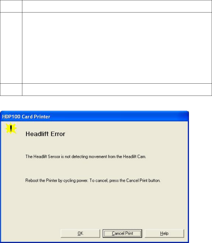
RESTRICTED USE ONLY Fargo Electronics, Inc.
HDP100 High Definition Card Printer/Encoder User Guide (Rev. Beta) 64
Resolving a Headlift Motor or Sensor Error
All Troubleshooting procedures assume that only factory-authorized supplies are in use in
the Printer.
Step Procedure
1 Review the following information.
Symptom: The Printhead continuously cycles or does not cycle at all
Printer Error State: Headlift Sensor is not detecting movement from the
Headlift Cam.
LCD Error Display: Headlift Error
Driver Monitor Error Display: General Error
2 Press the Cancel Print button on the Driver Monitor Error Display Message.

RESTRICTED USE ONLY Fargo Electronics, Inc.
HDP100 High Definition Card Printer/Encoder User Guide (Rev. Beta) 65
Resolving a Headlift Motor or Sensor Error
Step Procedure
3 Reboot the Printer by cycling the power.
4 Cycle the Headlift Motors.
a. Use the Fargo Diagnostic utility to cycle the Printhead to ensure proper
printhead operation. See the Card tab (Diagnostic button) in the
Printer Driver.
b. Verify that the Headlift Motor turns.
c. If the Motor does not turn or jams, continue to Step 5.
5 Check the Headlift Motor Main Board Connection (J20).
a. Unplug the Printer.
b. Remove the back Cover.
c. Verify that connection J20 is properly connected to the Main Board.
d. If the Motor does not turn, continue to Step 7.
6 Test the Headlift Sensor.
a. Remove the back Cover.
b. Attach the positive lead from a Digital Voltmeter to Pin 1 of J9. Attach
the negative lead to the Pin 3 of J9.
If open, the Sensor should read 0.17 to 0.9 VDC.
If closed, the Sensor should read 4.9 to 5.5 VDC.
c. Replace the Sensor if the voltages do not read correctly. (Note: See
the current HDP600 Service for related instructions in the Parts
Replacement Section.)
d. If the Motor does turn, continue to Step 7.
7 Replace the Headlift Motor. (Note: See the current HDP600 Service
Manual for related instructions in the Parts Replacement Section.)
a. If the Motor does turn, continue to Step 8.
8 Replace the Main Board.
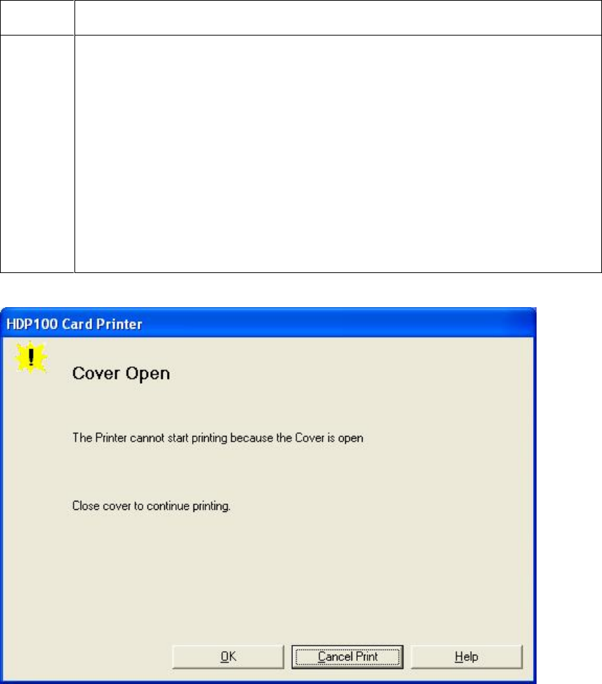
RESTRICTED USE ONLY Fargo Electronics, Inc.
HDP100 High Definition Card Printer/Encoder User Guide (Rev. Beta) 66
Resolving the Cover Open Error Message
All Troubleshooting procedures assume that only factory-authorized supplies are in use in
the Printer.
Step Procedure
1 Review the following information.
Symptom: The Printer errors immediately after sending a print job, or
the Rollers do not operate by pressing the buttons on the front panel
(when the Cover is open).
Printer Error State: The front Cover Sensor detects that the Cover is
open
LCD Error Display: Cover Is Open
Driver Monitor Error Display: None

RESTRICTED USE ONLY Fargo Electronics, Inc.
HDP100 High Definition Card Printer/Encoder User Guide (Rev. Beta) 67
Resolving the Cover Open Error Message
Step Procedure
2 Check for debris, as follows:
a. Open the front Cover and check that no debris has accumulated in the
lid Sensor opening. Use compressed air to clean the opening id as
needed.
b. If the Sensor still does not work, continue to Step 3.
3 Check that the Sensor tab on the front Cover is not damaged.
a. Open the front Cover and examine the Lid Sensor tab for damage, if the
Sensor tab is damaged, replace the front Cover. (Note: See the
current HDP600 Service Manual for related instructions in the Parts
Replacement Section.)
b. If the Sensor still does not work, continue to Step 4.
4 Replace the Main Board. (Note: See the current HDP600 Service Manual
for related instructions in the Parts Replacement Section.)

RESTRICTED USE ONLY Fargo Electronics, Inc.
HDP100 High Definition Card Printer/Encoder User Guide (Rev. Beta) 68
Resolving the Blank Output issues
All Troubleshooting procedures assume that only factory-authorized supplies are in use in
the Printer.
Step Procedure
1 Review the following information.
Symptom: A card is ejected blank (that should be printed).
Printer Error State: None
LCD Error Display: None
Driver Monitor Error Display: None
2 Run a self-test. See Running the Self-Test.
3 Look for an image on the Ribbon.
a. After a self-test has been run, open the top Cover.
b. Remove the Print Ribbon from the Printer.
c. Visually inspect the set of panels that were last used by the Printer.
d. If an image is noticeable on the used Ribbon, continue to Step 4.
e. If an image is not noticeable on the used Ribbon, continue to Step 5.

RESTRICTED USE ONLY Fargo Electronics, Inc.
HDP100 High Definition Card Printer/Encoder User Guide (Rev. Beta) 69
Resolving the Blank Output issues (continued)
Step Procedure
4 Adjust the placement.
a. Reset the Printer to clear any Error Messages by removing the power
and reapplying it.
b. Open the Printer Control Panel from the Computer.
If using Windows 98SE, Me, right click on the HDP600 Card Printer
Icon and select Properties.
If using Windows 2000/XP, right click on the HDP600 Card Printer
and select Printing Preferences.
c. Click on the Image Transfer tab.
d. Click on the Settings button.
e. Adjust the Image Placement Setting by +5.
f. Click on the OK button.
g. Print a self-test.
h. After adjusting the Image Placement, if a white border appears on the
card, adjust the image placement back toward its original value in
increments of 2 until the white edge is gone.
i. If still having blank card issues, continue to Step 5.
5 Check the Printhead connections.
a. Remove the Printer power and USB cables.
b. Turn the Printer over to gain access to the base plate.
c. Remove the one (1) thumbscrew from the Printhead Cover plate and
remove the Cover plate.
d. Depress the Printhead locking tabs and remove the Printhead.
e. Check to ensure that Power and Data Cables (that connect to the
Printhead) are properly seated.
f. Remove the Back Cover.
g. Ensure that the Printhead Power/Data Cable is properly seated on J16
on the Main Board.
h. If still having blank card issues, continue to Step 6.

RESTRICTED USE ONLY Fargo Electronics, Inc.
HDP100 High Definition Card Printer/Encoder User Guide (Rev. Beta) 70
Resolving the Blank Output issues
Step Procedure
6 Ensure that the proper voltage is being applied to the Printhead.
a. Remove the back Cover.
b. Using a Digital Voltmeter, connect the negative lead to ground.
c. Probe Pins 1 to 5 of the Printhead power connection on J16.
d. Ensure that a voltage between 22 to 23 VDC is read on each pin.
If less than 22 volts is read on any of the pins, replace the
Printhead.
If still having issue with blank cards, replace the Main Board. (See
the current HDP600 Service Manual for instructions on replacing
the Main Board in the Parts Replacement Section.)
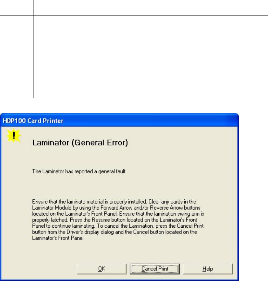
RESTRICTED USE ONLY Fargo Electronics, Inc.
HDP100 High Definition Card Printer/Encoder User Guide (Rev. Beta) 71
Card Lamination Errors
Resolving a Laminator (General Error)
Step Procedure
1 Review the following information.
Symptom: The Laminator has reported a general fault.
Printer Error State: The Laminator has reported a general fault.
LCD Error Display: Laminator (General Error)
Driver Monitor Error Display: Laminator (General Error)
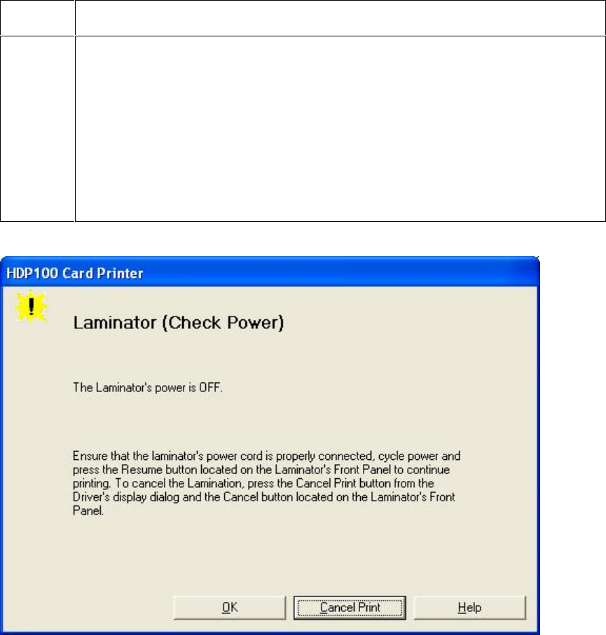
RESTRICTED USE ONLY Fargo Electronics, Inc.
HDP100 High Definition Card Printer/Encoder User Guide (Rev. Beta) 72
Resolving the Laminator (Check Power) Error
Step Procedure
1 Review the following information.
Symptom: The Laminator’s power is OFF.
Printer Error State: The Laminator’s power is OFF.
LCD Error Display: Laminator (Check Power)
Driver Monitor Error Display: Laminator (Check Power)

RESTRICTED USE ONLY Fargo Electronics, Inc.
HDP100 High Definition Card Printer/Encoder User Guide (Rev. Beta) 73
Resolving the Laminator (Heater Off) Error
Step Procedure
1 Review the following information.
Symptom: The Laminator’s Heater is OFF.
Printer Error State: The Laminator’s Heater is OFF.
LCD Error Display: Lam Heater Off
Driver Monitor Error Display: Laminator (Heater Off)
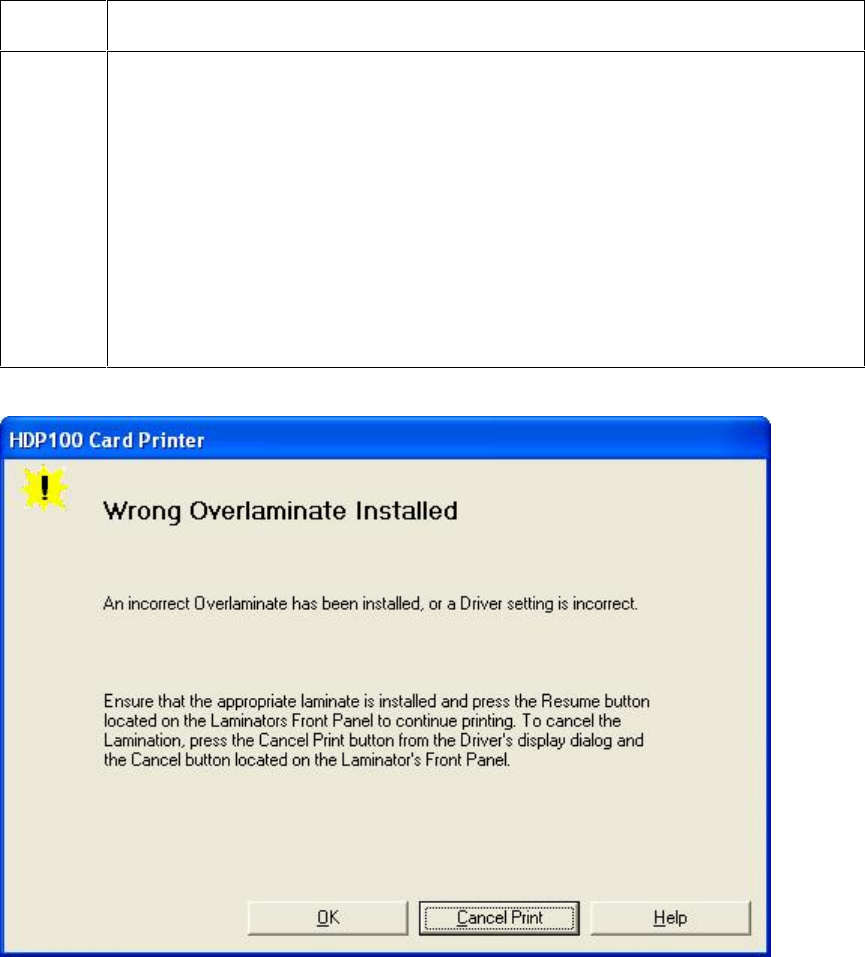
RESTRICTED USE ONLY Fargo Electronics, Inc.
HDP100 High Definition Card Printer/Encoder User Guide (Rev. Beta) 74
Resolving the Wrong Overlaminate Installed Error
Step Procedure
1 Review the following information.
Symptom: An incorrect Overlaminate has been installed, or a Driver
setting is incorrect.
Printer Error State: An incorrect Overlaminate has been installed, or a
Driver setting is incorrect.
LCD Error Display: Wrong Overlaminate Installed
Driver Monitor Error Display: Wrong Overlaminate Installed
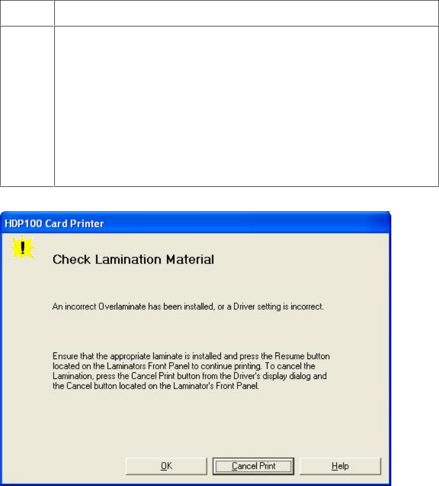
RESTRICTED USE ONLY Fargo Electronics, Inc.
HDP100 High Definition Card Printer/Encoder User Guide (Rev. Beta) 75
Resolving Check Lamination Material Error
Step Procedure
1 Review the following information.
Symptom: An incorrect Overlaminate has been installed, or a Driver
setting is incorrect.
Printer Error State: An incorrect Overlaminate has been installed, or a
Driver setting is incorrect.
LCD Error Display: Check Lam Material
Driver Monitor Error Display: Check Lamination Material
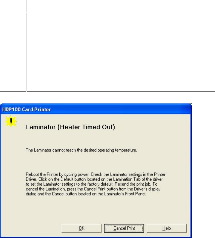
RESTRICTED USE ONLY Fargo Electronics, Inc.
HDP100 High Definition Card Printer/Encoder User Guide (Rev. Beta) 76
Resolving LAM Heater Times Out Error
Step Procedure
1 Review the following information.
Symptom: An incorrect Overlaminate has been installed, or a Driver
setting is incorrect.
Printer Error State: An incorrect Overlaminate has been installed, or a
Driver setting is incorrect.
LCD Error Display: Lam Heat Timeout
Driver Monitor Error Display: Check Lamination Material
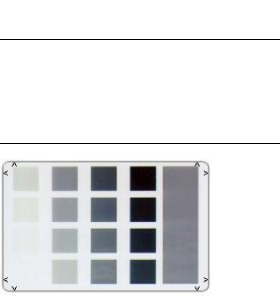
RESTRICTED USE ONLY Fargo Electronics, Inc.
HDP100 High Definition Card Printer/Encoder User Guide (Rev. Beta) 77
Printing a Test Image
Step Procedure
1 Choose Print Test Image to select a preset test image. (Note: These images
help to determine if the Printer is functioning properly.)
2 Scroll to the desired test image from the Select Test Image options and press
the Select button.
Reviewing the Gray/Align YMC/K Self-Test
Step Procedure
1 Use this card to determine Image Placement and confirm that the Printer is
working properly. See Printer Adjustments. (Note: The image consists of sixteen
(16) gray scale boxes and alignment arrows. The gray boxes are composed from
a composite of YMC color panels.)
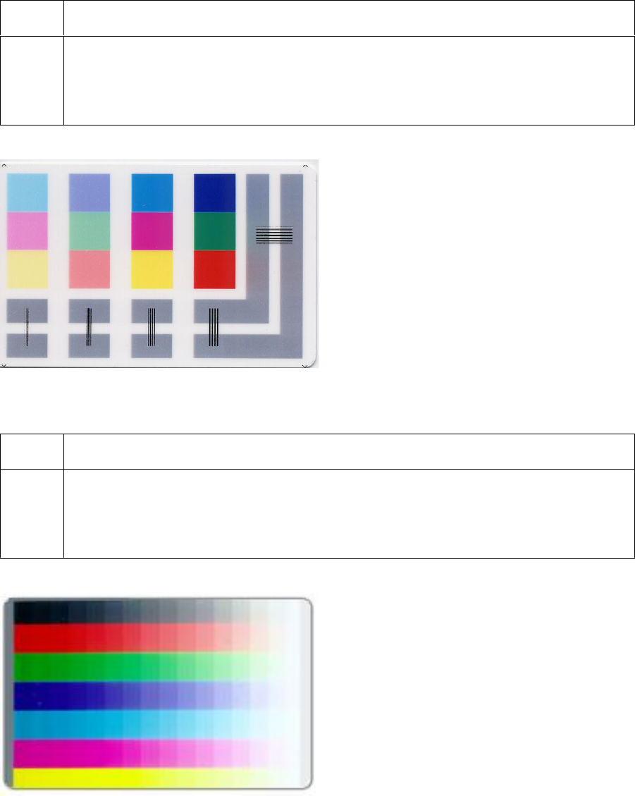
RESTRICTED USE ONLY Fargo Electronics, Inc.
HDP100 High Definition Card Printer/Encoder User Guide (Rev. Beta) 78
Reviewing the Color/Resin YMCK Self-Test
Step Procedure
1 Use this card to determine Image Placement and confirm that (a) the image
colors are properly reproduced and (b) the Resin Panel is printing properly.
(Note: The Image consists of twelve spot colors, YMC and RGB, as well as gray
density bars and thin resin lines.)
Reviewing the Color Bars YMC Self-Test
Step Procedure
1 Use this card to confirm that image colors are properly reproduced. Image
consists of sixteen graduated steps of RGB and YMCK. (Note: This print will
provide maximum image size, giving complete card Coverage on a CR-80 sized
card.)

RESTRICTED USE ONLY Fargo Electronics, Inc.
HDP100 High Definition Card Printer/Encoder User Guide (Rev. Beta) 79
Reviewing the Card Count Self-Test
Step Procedure
1 Use this card to view counts for Card Count (CC), Pass Count (PC), Transfer
Count (TC) and Lamination Count (LC).
The Card Count is the total number of cards the Printer has produced. Pass
Count is the total number of print passes made by the Printhead. (Note: A
pass is measured each time a single Ribbon panel is printed or passes
beneath the Printhead.)
The Transfer Count is the total number of times the Printer transfers an
image to a card.
Reviewing the Magnetic Test option
Step Procedure
1 Use this option only applies if a Magnetic Encoding Module is installed in the
Printer. (Note: The Printer will feed, encode and eject a card. Be sure to have
high coercivity cards installed when running this test.)
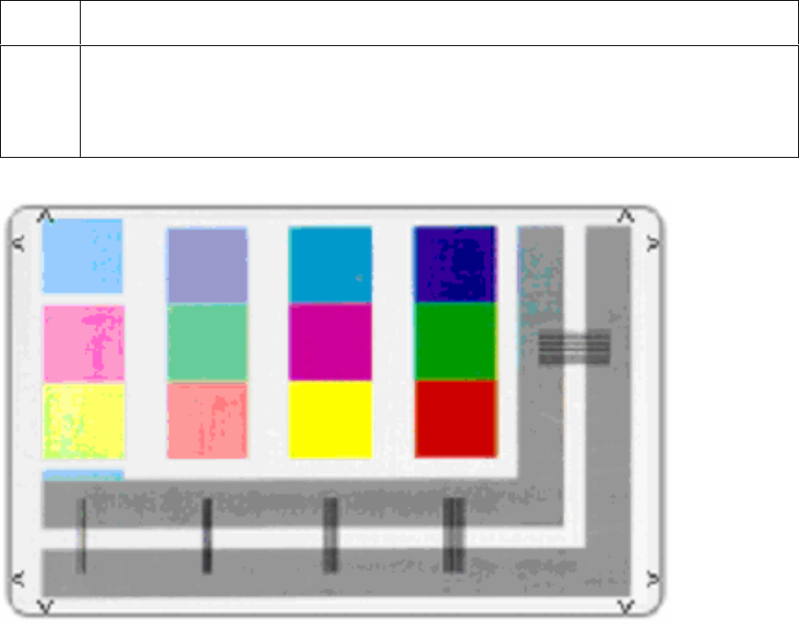
RESTRICTED USE ONLY Fargo Electronics, Inc.
HDP100 High Definition Card Printer/Encoder User Guide (Rev. Beta) 80
Reviewing the Lamination Color/Resin YMCK+L Self-Test
Step Procedure
1 Use this card to determine Lamination Placement and confirm that (a) the image
colors are properly reproduced and (b) the Resin Panel is printing properly.
(Note: The Image consists of twelve spot colors, YMC and RGB, as well as gray
density bars and thin resin lines.)