Feig Electronic CPR74 RF Reader User Manual CPR74 Manual M60610 0ex
Feig Electronic GmbH RF Reader CPR74 Manual M60610 0ex
Contents
UserManual.pdf
MANUAL
priliminary – public (B)
2016-09-26 – CPR74-Manual
M60610-0e.docx
ID CPR74
RFID-Readermodul
Modell Artikel-Nr..
ID CPR74-4SCUSB 4607.000.00
ID CPR74-CUSB 4606.000.00

OBID® classic-pro Installation ID CPR74
FEIG ELECTRONIC GmbH Page 2 of 20 CPR74-Manual M60610-
0e.docx
Note
Copyright 2016 by
FEIG ELECTRONIC GmbH
Lange Strasse 4
D-35781 Weilburg
Tel.: +49 6471 3109-0
http://www.feig.de
With the edition of this document, all previous editions become void. Indications made in this manual may be
changed without previous notice.
The reproduction, distribution and utilization of this document as well as the communication of its contents to
others without express authorization is prohibited. Offenders will be held liable for the payment of damages.
All rights reserved in the event of the grant of a patent, utility model or design.
Composition of the information in this document has been done to the best of our knowledge. FEIG
ELECTRONIC GmbH does not guarantee the correctness and completeness of the details given in this
manual and may not be held liable for damages ensuing from incorrect or incomplete information. Since,
despite all our efforts, errors may not be completely avoided, we are always grateful for your useful tips.
The instructions given in this manual are based on advantageous boundary conditions. FEIG ELECTRONIC
GmbH does not give any guarantee promise for perfect function in cross environments and does not give
any guaranty for the functionality of the complete system which incorporates the subject of this document.
FEIG ELECTRONIC call explicit attention that devices which are subject of this document are not designed
with components and testing methods for a level of reliability suitable for use in or in connection with surgical
implants or as critical components in any life support systems whose failure to perform can reasonably be
expected to cause significant injury to a human. To avoid damage, injury, or death, the user or application
designer must take reasonably prudent steps to protect against system failures.
FEIG ELECTRONIC GmbH assumes no responsibility for the use of any information contained in this
document and makes no representation that they free of patent infringement. FEIG ELECTRONIC GmbH
does not convey any license under its patent rights nor the rights of others.
OBID® and OBID i-scan® is a registered trademark of FEIG ELECTRONIC GmbH.
All brand names, trademarks or logos are property of their respective owners.

OBID® classic-pro Installation ID CPR74
FEIG ELECTRONIC GmbH Page 3 of 20 CPR74-Manual M60610-
0e.docx
Content
1. Safety Instructions / Warning - Read before start-up ! 4
2. Characterization ID CPR74 5
2.1. Scope of delivery .................................................................................................................. 6
2.2. Available Accessories ......................................................................................................... 6
2.3. Available Software Tools, USB Driver and Firmware ....................................................... 6
3. Dimensions 7
4. Installation and wiring 8
4.1. Connector X1, X2 .................................................................................................................. 8
4.2. Digital Outputs ...................................................................................................................... 9
4.3. Connection of an external Antenna .................................................................................. 10
4.4. SAM Slots ............................................................................................................................ 11
4.4.1. Installation of a SAM Card in a SAM Socket ................................................................ 12
5. Power supply 13
5.1. Power via USB Interface .................................................................................................... 13
5.2. Standby- / Wake-up-by-Card-Mode ................................................................................... 13
6. Indicators / LEDs 14
7. Installation notes 15
7.1. Metallic surroundings ........................................................................................................ 15
7.2. EMC effects on cables ....................................................................................................... 15
7.3. EMC effects from magnetic fields ..................................................................................... 16
8. Technical Data 17
9. Approvals 19
9.1. Europa (CE) ......................................................................................................................... 19
9.2. USA (FCC) and Canada (IC) ............................................................................................... 20

OBID® classic-pro Installation ID CPR74
FEIG ELECTRONIC GmbH Page 4 of 20 CPR74-Manual M60610-
0e.docx
1. Safety Instructions / Warning - Read before start-up !
The device may only be used for the intended purpose designed by for the
manufacturer.
The operation manual should be conveniently kept available at all times for each user.
Unauthorised changes and the use of spare parts and additional devices which have not
been sold or recommended by the manufacturer may cause fire, electric shocks or
injuries. Such unauthorised measures shall exclude any liability by the manufacturer.
The liability-prescriptions of the manufacturer in the issue valid at the time of purchase
are valid for the device. The manufacturer shall not be held legally responsible for
inaccuracies, errors, or omissions in the manual or automatically set parameters for a
device or for an incorrect application of a device.
Repairs may only be executed by the manufacturer.
Installation, operation, and maintenance procedures should only be carried out by
qualified personnel.
Use of the device and its installation must be in accordance with national legal
requirements and local electrical codes .
When working on devices the valid safety regulations must be observed.
Special advice for carriers of cardiac pacemakers:
Although this device doesn't exceed the valid limits for electromagnetic fields you
should keep a minimum distance of 25 cm between the device and your cardiac pace-
maker and not stay in an immediate proximity of the device respective the antenna for
some time.
OBID® classic-pro Installation ID CPR74
FEIG ELECTRONIC GmbH Page 5 of 20 CPR74-Manual M60610-
0e.docx
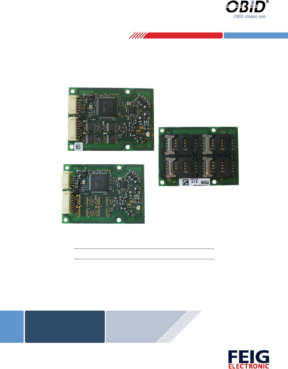
2. Characterization ID CPR74
The reader modules ID CPR74 are designed for data exchange (read and write) with passive tran-
sponder according ISO14443 type A and type B, ISO15693, ISO18000-3M3 and are capable for
communication with NFC devices (ISO18092). The small dimensions and the different available
interfaces (RS232-TTL or USB) make it suitable for an easy integration into terminals, housings
and other devices.
The following different types of reader modules are available:
ID CPR74-4SCUSB ID CPR74-CUSB
Dimensions L x B x H 50 mm x 68 mm x 10 mm 50 mm x 68 mm x 8 mm
Power supply 5 V DC ± 5 %
Antenna:
internal
external
SAM Socket 4 -
Digital outputs 3
Interface
RS232-TTL
USB full-speed (12Mbit/s)
The variant ID CPR74-4SCUSB is equipped with 4 sockets for Security Access Modules (SAM) in
the ID000 format. Because of the SAM current consumption the reader module is designed as
Self-Powered-Device and need a separate power supply. The voltage supply from a USB port is
not sufficient in this case.
Because of their high performance and a wide range of different configuration parameters the
reader modules ID CPR74 is suitable for a lot of applications like eTicketing, ePayment,
eDocument, eMobility and medical devices.
With the help of the integrated antenna multiplexer an external antenna can be used additional to
the internal antenna. In Scan Mode the reader can switch between both antenna automatically.
The implemented SoftCrypto and SAMCrypto high level functions offer a comfortable and fast in-
terface for the access to the encrypted data of an mifare Desfire, mifare Plus or mifare Ultralight
transponder.
The reader module with a corresponding external antenna is ready for a EMVCo Contactless Level
1 certification as well as a VDV-KA certification (corresponding to BSI TR-03105 Part 4) or in the
future CEN/TS 16794 approval.
The certification suitability need to be evaluate for each individual case because of the used ex-
ternal antenna and the installation situation.
The SAM Sockets have been approved according the EMVCo Contact Level 1 and they are eligi-
ble for the certification.

OBID® classic-pro Installation ID CPR74
FEIG ELECTRONIC GmbH Page 6 of 20 CPR74-Manual M60610-
0e.docx
2.1. Scope of delivery
The delivery contains the following parts:
1 x RFID-Reader module ID CPR74
2.2. Available Accessories
Tab. 1 Available Accessories and spare parts
Part Number Part name Description
3674.000.00 ID ISC.ANT40/30-U.FL-A
50 Ohm Antennae with U.FL-connector for the connection
on the ID CPR74
Dimensions: 40 mm x 30 mm
3673.000.00 ID ISC.ANT100/100-U.FL-A
50 Ohm Antennae with U.FL-connector for the connection
on the ID CPR74
Dimensions: 100 mm x 100 mm
3540.000.00 ID ISC.ANT.C05-A
50 Ohm Antenna cable with U.FL connector on both sides
for the connection of an external antenna on the ID
CPR74
Dimension : 500 mm; Color: black
3541.000.00 ID CAB.USB-B
USB-cable for the connection of the ID CPR74 on an ex-
ternal host
Dimension: 2,75 m
2.3. Available Software Tools, USB Driver and Firmware
The USB driver and the test and configuration tool “ID CPRStart” are available on our Feig down-
load area:
http://www.feig.de/en/downloads-support.html
Username: CPR74
Password : FE900
For firmware updates we are providing a update tool “OBIDFirmwareUpdateTool” and a external
firmware xml-file.
OBID® classic-pro Installation ID CPR74
FEIG ELECTRONIC GmbH Page 7 of 20 CPR74-Manual M60610-
0e.docx
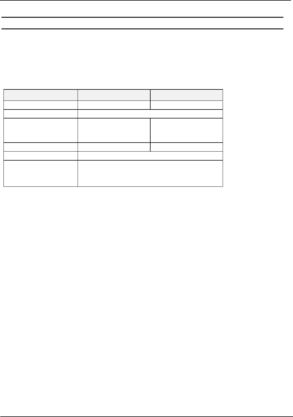
3. Dimensions
The ID CPR74 reader module has been designed for the integration into terminals, printers or
handheld devices and so on.
Figure 1: Dimension (Top View)
Figure 2: Dimension (Side View)
OBID® classic-pro Installation ID CPR74
FEIG ELECTRONIC GmbH Page 8 of 20 CPR74-Manual M60610-
0e.docx
4. Installation and wiring
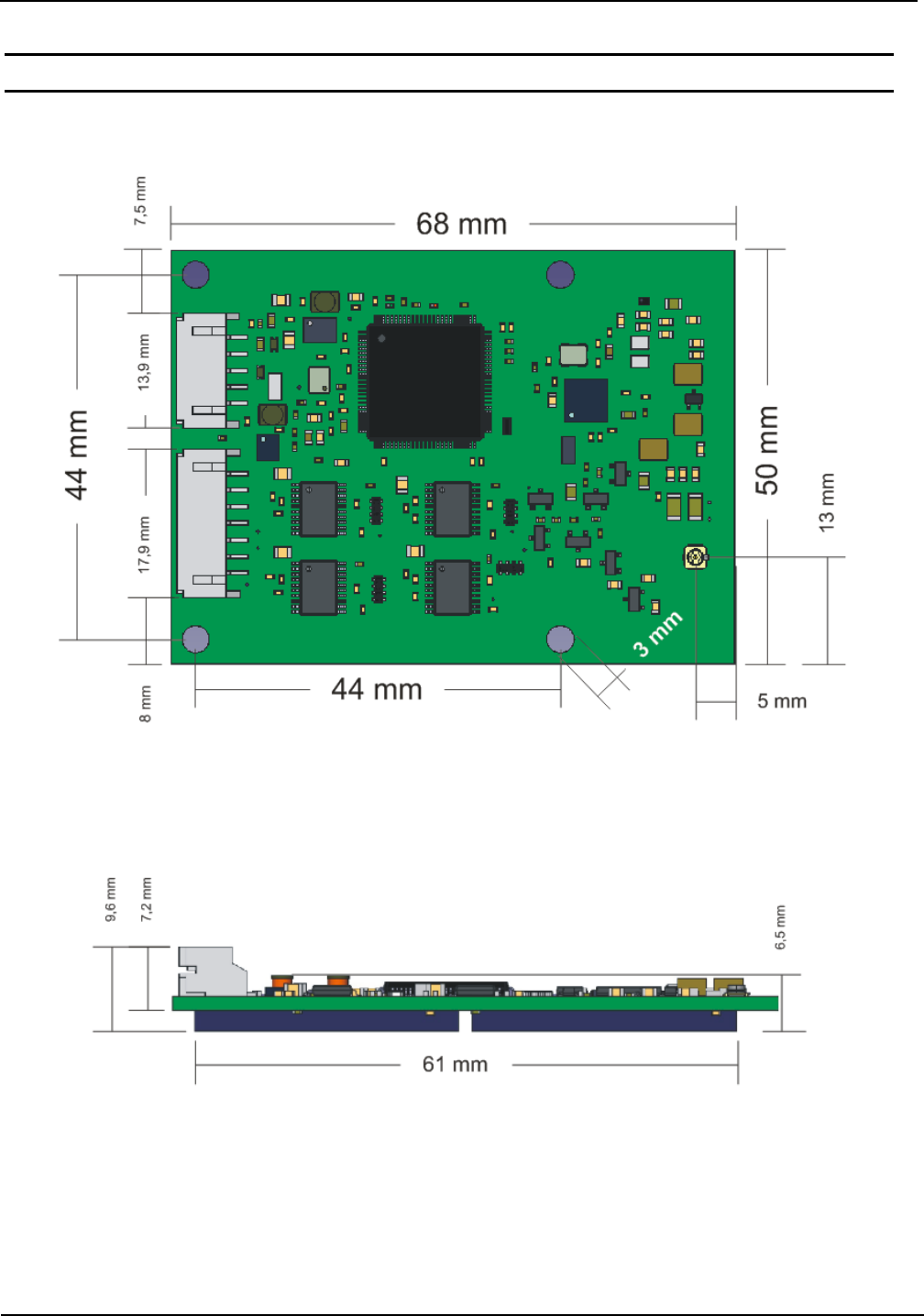
4.1. Connector X1, X2
The reader can be connected to a RS232-TTL interface and the power supply by using the multi-
pin connector X1. The multi-pin connector X2 provide the connection for the USB interface. The
device with SAM Sockets is a self-powered USB device which requires a separate power supply.
The following figure 4 and the table shows the assignment of the pins X1 (7pol.) and X2 (5pol.) Typ
“JST PH” RM 2 mm (horizontal).
Tab. 2 Assignment of the pins on X1 and X2
X1
Pin-No. Symbol ID CPR74
1 OUT1 Digital Output 1
2 OUT2 Digital Output 2
3 OUT3 Digital Output 3
4 GND*
5 RxD RS232-TTL
6 TxD RS232-TTL
7 VCC** + 5 V DC 5 %
X2
Pin-No.
1 Shielding USB-Cable Shielding
2 GND*
3 USB-D PLUS
4 USB-D MINUS
5 VCC** + 5 V DC 5 %
* GND are connected internal directly
** VCC are connected internal directly. Feed-In VCC only at one pin! This is especially important if
the reader is connected to a USB port. Please take care!
X1
1
5
1
7
X2
Figure 3: Plug „JST PH“
Figure 4: ID CPR74 - plug and connections
OBID® classic-pro Installation ID CPR74
FEIG ELECTRONIC GmbH Page 9 of 20 CPR74-Manual M60610-
0e.docx
NOTICE:
Only one host interface can be used at the same time. Using several host interfaces at
the same time can force malfunctions.
The reader has to supplied by a limited power supply (e.g. NEC Class 2/LPS power sup-
ply) according IEC EN 60950-1 chapter 2.5, only
Use only regulated power supply’s.
The connection cable (RS232TTL, USB, VCC) should be as short as possible and must be
shorter than 3 m to reduce the influence of noise.
Reversing the polarity of the supply voltage may destroy the device.
Supply voltages outside the specifications may destroy the device.
If switching power supplies are used with the module, be sure that there is adequate fil-
tering.
Noise from the power supply can result in a reduction of the read/write range of the
module.
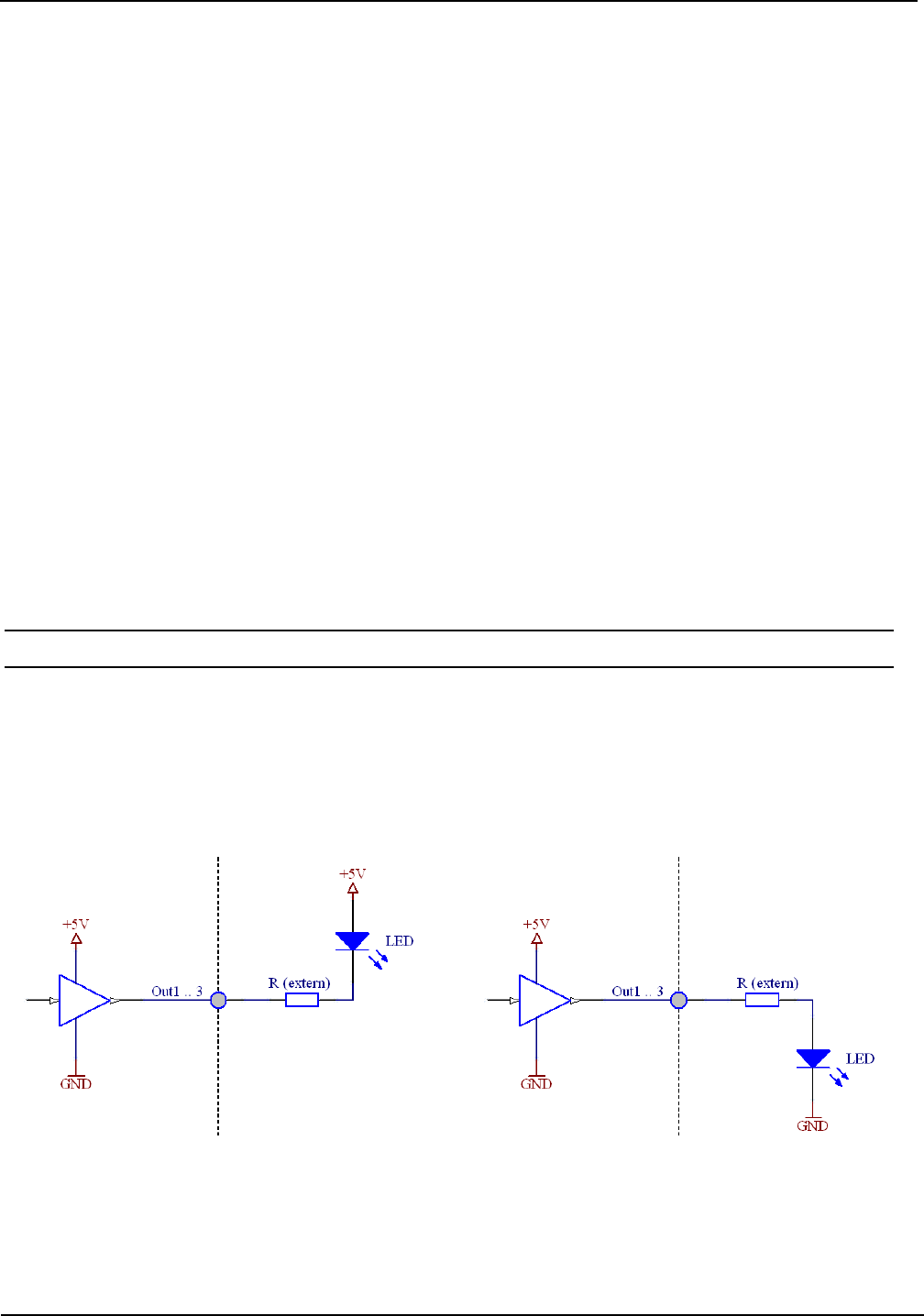
4.2. Digital Outputs
The Figure 5 shows the circuit diagram of the digital outputs OUT1 – OUT3. The digital outputs are
intended for the connection of external LED’s.
Figure 5: Wiring of digital outputs OUT1...3
OBID® classic-pro Installation ID CPR74
FEIG ELECTRONIC GmbH Page 10 of 20 CPR74-Manual M60610-
0e.docx
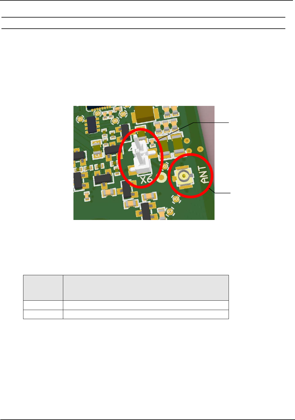
4.3. Connection of an external Antenna
The ID CPR74 modules are equipped with an internal 50 -antenna and have an addi-
tionally connector for an external 50 -antenna.
In Scan mode it is possible to switch between the two antennas automatically. In the
ISOHost Mode the switching of the antenna can be performed by commands.
The use of the external antenna is configurable in the reader settings.
The connection of the external antenna is possible via the U.FL connector „ANT“. Optional
it is possible to integrate a 2-pin SMD connector (spacing 2,54 mm) on position X6.
Figure 6: Connection of an external antenna
The technical description and hints for building external 50 -antennas can be taken from
the application note N20901-#d-ID-B.pdf.
Name Description
ANT Subminiature – Coaxial connector for an external 50 -antenna
X6 Optional 2pin. connector for an external 50
-antenna
NOTICE:
Only for use with 50 matched external antennas. The permanent usage of unmatched
antennas can damage the reader electronic.
The antenna output is neither permanent short circuit protected nor permanent no-load
protected.
The antenna cable should be no longer than 1m. The use of other cable length are pos-
sible after consulting the manufacturer.
ANT:
(
U.FL
)
X6:
Optionale
2 pol. SMD Stift-
leiste
OBID® classic-pro Installation ID CPR74
FEIG ELECTRONIC GmbH Page 11 of 20 CPR74-Manual M60610-
0e.docx
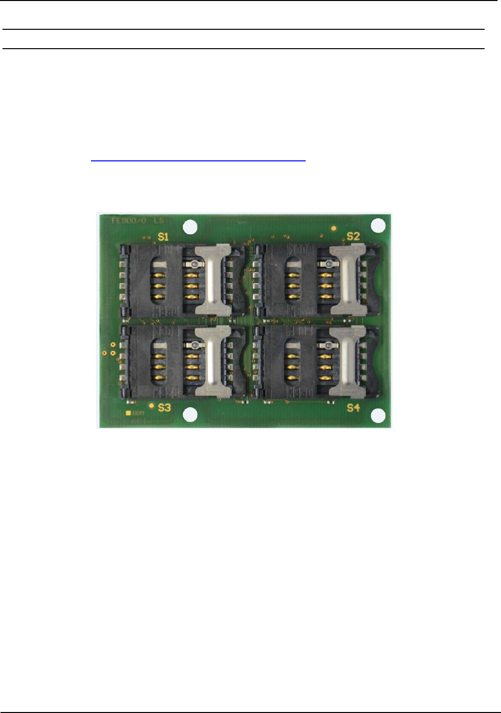
4.4. SAM Slots
Figure 7 shows the position of the 4 SAM slots (S1-4). Each SAM slot is designed for a ID000
formatted SAM Card.
NOTICE
Wrong inserted SAM cards and forcefully opening or closing can damage the SAM slot.
See chapter: 4.4.1. Installation of a SAM Card in a SAM
Figure 7: Position of the 4 SAM Sockets
OBID® classic-pro Installation ID CPR74
FEIG ELECTRONIC GmbH Page 12 of 20 CPR74-Manual M60610-
0e.docx
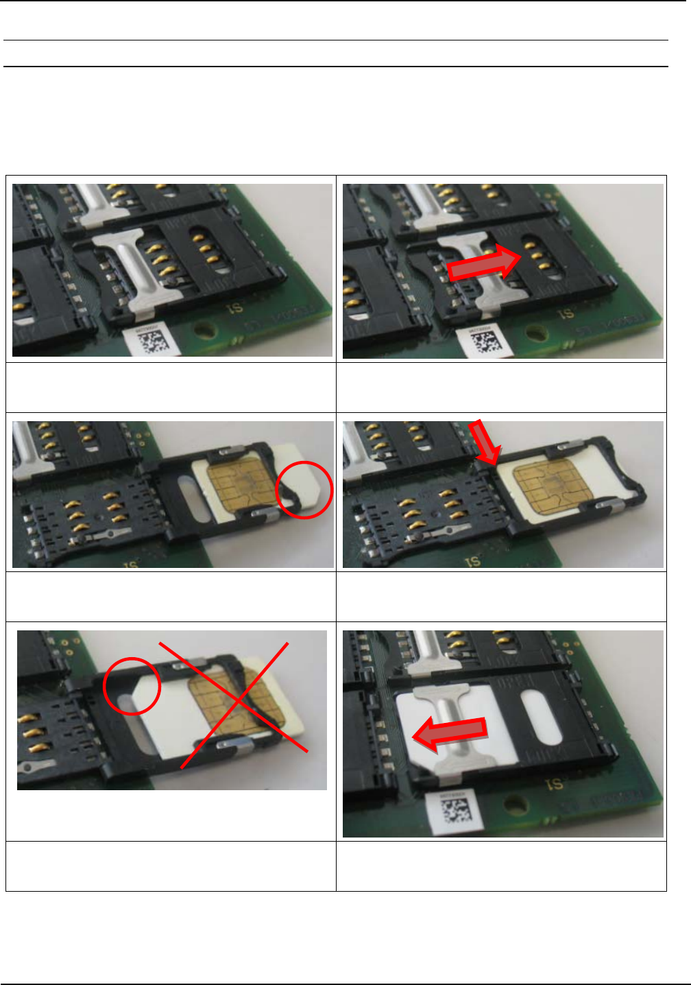
4.4.1. Installation of a SAM Card in a SAM Socket
The following step by step instruction shows the installation of a SAM Card into the SAM socket
S1.
1. Closed SAM socket without SAM card. 2. Push the latch to the right side and open the
cover carefully.
3. Put the SAM card into the cover. The contact
plate face up and the beveled corner outside
4. The SAM card must be pushed up against
the stop angle.
5. The SAM card must not be inserted with the
beveled corner first.
6. Close the top cover with carefully pressure to
snap into place. Push the latch to the left side.

OBID® classic-pro Installation ID CPR74
FEIG ELECTRONIC GmbH Page 13 of 20 CPR74-Manual M60610-
0e.docx
5. Power supply
The reader ID CPR74-SCUSB with 4 SAM slots is designed as a “Self-Powered USB Device” and
needs an additional 5 V DC power supply.
The power supply must meet the following specification:
+5 V DC ± 5 %
Ripple:
0...250 kHz < 10 mVpp
from 250 kHz < 0,1 mVpp
Note:
On both device variants you need to take care that the voltage supply of the USB port is
not connected in the case if an external power supply is connected.
5.1. Power via USB Interface
The reader ID CPR74-CUSB (without SAM-Sockets) can be optional powered via a High Powered
USB port (500mA).
5.2. Standby- / Wake-up-by-Card-Mode
The Standby mode or the Wake-up-by-Card function can be configured in the reader configura-
tion. See system manual „H60410-xe-ID-B.pdf“.
NOTICE:
The reader can be set into the Standby mode or the Wake-up-by-Card mode with the
command 0x64 System Reset, see system manual H60410-xe-ID-B. The command can be
executed via the RS232-TTL interface only and not via the USB interface.
OBID® classic-pro Installation ID CPR74
FEIG ELECTRONIC GmbH Page 14 of 20 CPR74-Manual M60610-
0e.docx
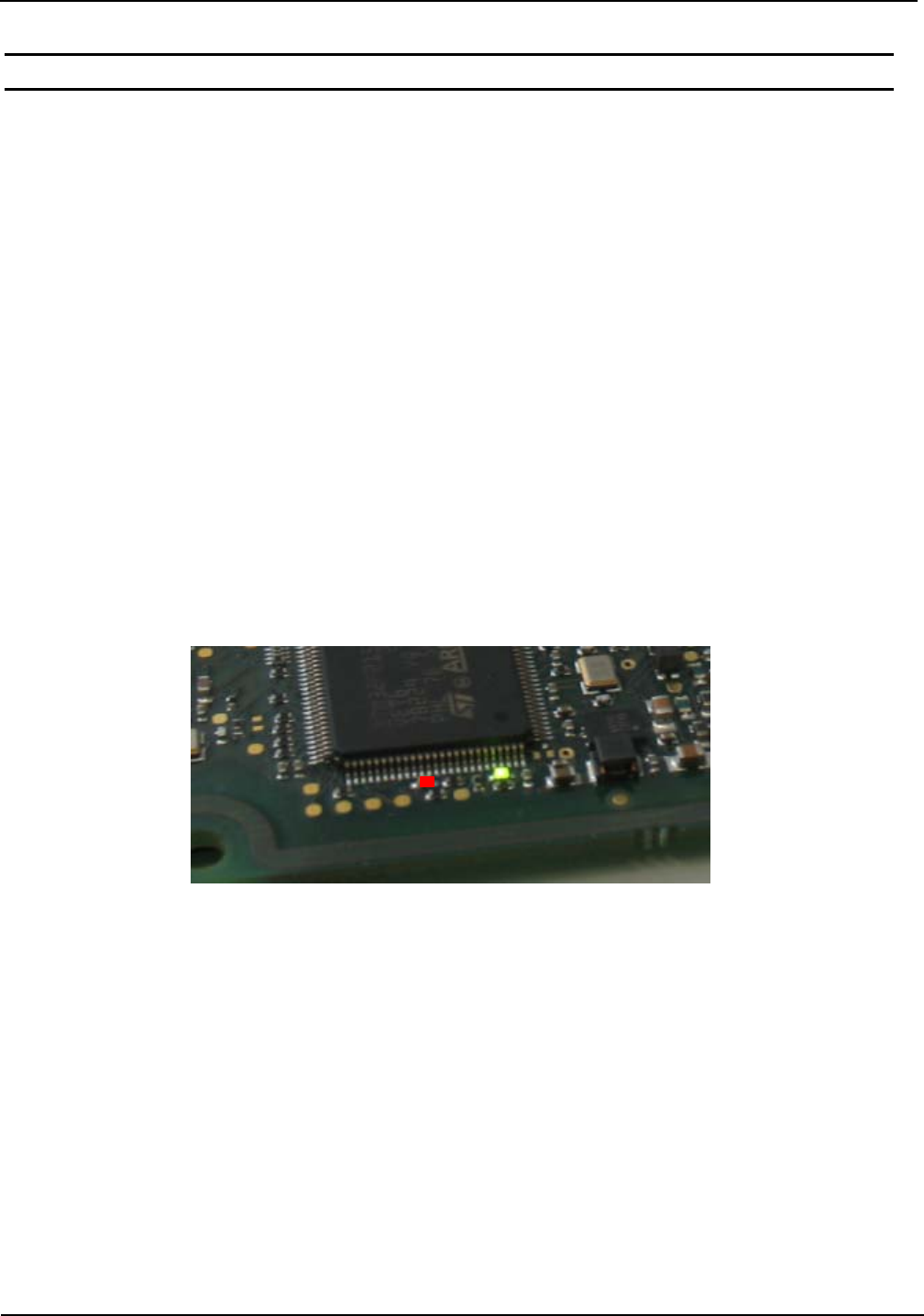
6. Indicators / LEDs
The reader modules has two LED indicators on board (green and red)
After power on or after a CPU Reset both LED’s starts blinking synchronously for about 2s.
While operation the LED’s signalizes the following operating status:
LED - green
flashes:
Reader is ready for operation but has no host communication
shine:
Polling-Mode:
Reader is ready for work and has communication with the host.
Scan-Mode:
Reader is working in Scan-Mode.
LED - rot
Communication with the Transponder (Tag detect).
Figure 8 shows the position of the green and red LED.
Figure 8: Position of the green and red LED

OBID® classic-pro Installation ID CPR74
FEIG ELECTRONIC GmbH Page 15 of 20 CPR74-Manual M60610-
0e.docx
7. Installation notes
Be aware of the following possible environmental factors when installing an ID CPR74 into another
device :
Effects from nearby metal objects
Detuning of the integrated antenna
Impaired communication of the antenna’s magnetic field
EMC effects on cables
Impaired communication between reader and transponder
EMC effects from magnetic fields
Impaired communication between reader and transponder
7.1. Metallic surroundings
When installing an ID CPR74 into another device, be sure that there are no metal surfaces or ob-
jects in the direct vicinity of the reader if possible. These can detune the antenna and thus reduce
the magnetic field of the integrated antenna. This will in turn result in reduced read distances for
the reader.
The distance between the reader and a metal surface should be at least 3 cm. Note that
even other circuit boards may act like metal objects depending on how much copper they
contain.
If a metallic surrounding cannot be avoided, stable function should at least be ensured by keeping
the distance as great as possible.
The area between the antenna and transponder as well as the area on the other side of the tran-
sponder should also be kept clear of metal parts.
Since any change in the metallic environment will result in detuning of the integrated antenna and
therefore to impaired function, no moving metal parts, such as metallic fans, should be allowed in
the vicinity of the reader.
7.2. EMC effects on cables
In spite of the internal EMC filters inside the reader, high levels of noise on the supply voltage can
result in impairment of the communication between the reader and transponder.
When installing an ID CPR74 into another device, be sure therefore that a clean, noise-free power
supply is used.

OBID® classic-pro Installation ID CPR74
FEIG ELECTRONIC GmbH Page 16 of 20 CPR74-Manual M60610-
0e.docx
7.3. EMC effects from magnetic fields
The communication principle of RFID- Technology is based on the modulation of electromagnetic
fields. Alternating magnetic fields in the vicinity of the antenna can have a negative influence on
the reader function.
Sources of such magnetic interference fields include coils within a primary or secondary switching
power supply.
When determining the position of the reader and antenna within a device, check the device for any
possible sources of interference as described above. If necessary, use shielding to suppress such
interference.

OBID® classic-pro Installation ID CPR74
FEIG ELECTRONIC GmbH Page 17 of 20 CPR74-Manual M60610-
0e.docx
8. Technical Data
Tab. 3: Technical data
ID CPR74
Weight approx. 20 g
Temperature Range Operating -25 °C up to +70 °C (-13 °F up to +158 °F)
Storage -40 °C up to +85 °C (-40 °F up to +185 °F)
Humidity max. 95 % (not condensing)
MTBF 500 000 h
Power Supply
+5 V DC ± 5 %
Ripple:
0...250 kHz < 10 mVpp
from 250 kHz < 0,1 mVpp
Current Consumption < 500 mA (without SAM)
Standby-Mode/Sleep-Mode
Interfaces USB Full-Speed (12 Mbit/s), Self-Powered Device
RS232-TTL 4 800 – 230 400 Baud
Driver
OBID® USB Driver, PC/SC-Driver (WHQL)
Windows® Server 2003 und 2008,
Windows® Vista 32/64 Bit, Windows® 7 32/64 Bit,
Windows® 8 32/64 Bit, Windows® 10 32/64 Bit,
Windows® CE
Software Development Kits Windows®, Windows® CE and Linux (C++, .NET, JAVA)
I/Os 3 digital outputs; max. 20 mA
2 LED’s (green, red)
RFID Interface ISO 14443-A/-B (106 … 848 kBit/s)
ISO 15693, ISO 18000-3M3
Operating Frequency 13,56 MHz
Output Power 450 mW
Antenna Connection U.FL-Socket for external antenna
Supported Transponder Types (contactless)
ISO/IEC 14443-4, mifare® classic, mifare® UltraLight,
mifare® DESFire, mifare® PLUS, mifare® UltraLight C,
my-d® move, JewelTM, FeliCa.
Tag-It HFI, Fujitsu MB89R11x, STM24LRx, STMLRI2k,
I-Code SLI/SLIX, I-Code ILT
NFC Devices in Card Emulation Mode (Tag Type 1…4),
NFC Peer-to-Peer (P2P)
Contact Interface 4 SAM-Module (size ID000) according to ISO 7816
T=0 and T=1 Protocol, Power Class A, B & C
Operating Modes ISOHost Mode ( Polling Mode), Scan-Mode

OBID® classic-pro Installation ID CPR74
FEIG ELECTRONIC GmbH Page 18 of 20 CPR74-Manual M60610-
0e.docx
Radio Approval
Europe EN 300 330
USA FCC 47 CFR Part 15
Canada IC RSS-210
EMV EN 301 489
Safety and Health EN 62368
EN 50364
Waste and Hazardous Substances WEEE - 2002/96/EC
RoHS - 2011/65/EC
Miscellaneous
Tested according EMVCo Contact Level 1
Certification suitability according EMVCo Contactless Level 1,
VDV-KA,ITSO and in the future CEN/TS 16794 (see chap-
ter: 2. Characterization ID CPR74)
OBID® classic-pro Installation ID CPR74
FEIG ELECTRONIC GmbH Page 19 of 20 CPR74-Manual M60610-
0e.docx
9. Approvals
9.1. Europa (CE)
Hereby, FEIG ELECTRONIC GmbH declares that the radio equipment type ID CPR74 is in com-
pliance with Directive 2014/53/EU.
The full text of the EU declaration of conformity is available at the following internet address:
http://www.feig.de/en/downloads-support/declarations-of-conformity.html
Performance Classification according to ETSI EN 301 489: Class 2

OBID® classic-pro Installation ID CPR74
FEIG ELECTRONIC GmbH Page 20 of 20 CPR74-Manual M60610-
0e.docx
9.2. USA (FCC) and Canada (IC)
Product name: ID CPR74
FCC ID:
IC:
PJMCPR74
6633A-CPR74
Notice for USA
and Canada
This device complies with Part 15 of the FCC Rules and with
RSS-210 of Industry Canada.
Operation is subject to the following two conditions.
(1) this device may not cause harmful interference, and
(2) this device must accept any interference received,
including interference that may cause undesired operation.
Unauthorized modifications may void the authority granted under Federal
communications Commission Rules permitting the operation of this device.
This equipment has been tested and found to comply with the limits for a Class A
digital device, pursuant to Part 15 of the FCC Rules. These limits are designed to
provide reasonable protection against harmful interference when the equipment is
operated in a commercial environment. This equipment generates, uses, and can
radiate radio frequency energy and, if not installed and used in accordance with
the instruction manual, may cause harmful interference to radio communications.
Operation of this equipment in a residential area is likely to cause harmful
interference in which case the user will be required to correct the interference at
his own expense.
Le présent appareil est conforme aux CNR d'Industrie Canada applicables aux
appareils radio exempts de licence. L'exploitation est autorisée aux deux condi-
tions suivantes :
(1) l'appareil ne doit pas produire de brouillage, et
(2) l'utilisateur de l'appareil doit accepter tout brouillage radioélectrique subi,
même si le brouillage est susceptible d'en compromettre le fonctionnement.
Warning: Changes or modification made to this equipment not expressly approved by
FEIG ELECTRONIC GmbH may void the FCC authorization to operate this equipment.
Installation with FCC / IC Approval:
FCC-/IC-NOTICE: To comply with FCC Part 15 Rules in the United States / with IC Radio Stand-
ards in Canada, the system must be professionally installed to ensure compliance with the Part 15
certification / IC certification. It is the responsibility of the operator and professional installer to en-
sure that only certified systems are deployed in the United States / Canada.