Feig Electronic MWDBF Radar Motion Detector User Manual manual
Feig Electronic GmbH Radar Motion Detector manual
Contents
- 1. Users Manual
- 2. Revised Users Manual
Users Manual

22.08.02
Instruction manual
Digital Radar Motion Detector
with Infrared Remote Control
MWD BF
FEIG ELECTRONIC GmbH Lange Straße 4 35781 Weilburg/Lahn

MWD BF Instruction manual
208/02 FEIG ELECTRONIC GmbH
General
Copyright 2002 by FEIG ELECTRONIC GmbH
Lange Straße 4
D - 35781 Weilburg
The indications made in these operating instructions may be altered without previous notice.
With the edition of these instructions, all previous editions become void.
Composition of the information given in this manual has been done to the best of our
knowledge. FEIG ELECTRONIC does not guarantee the correctness of the details given in
these instructions and may not be held liable for damages ensuing from incorrect installation.
Since, despite of all our efforts, errors may not be completely avoided, we are always grateful
for your useful tips.
The installation instructions given in this manual are based on advantageous boundary
conditions. FEIG ELECTRONIC does not give any guarantee promise for perfect function of the
traffic detector in a cross surrounding.
Copy or reproduction of these instructions, even if only partial, as well as translation into other
languages is forbidden unless a written consent has been granted by FEIG ELECTRONIC. This
also applies to the complete or partial storage of these operating instructions on modern input-
and output media for further processing in data processing systems.
Please read the operating- and safety instructions thoroughly before putting the motion
detector into operation!!
BES_BF_eng.DOC, L-16657
Stand: 22.08.02

Instruction manual MWD BF
FEIG ELECTRONIC GmbH 08/02 3
Contents
FUNCTIONAL DESCRIPTION.....................................................................................................4
2INSTALLATION....................................................................................................................5
2.1 Place of installation.........................................................................................................5
2.2 Mounting of the bracket..................................................................................................5
2.3 How to connect the motion detector .............................................................................5
2.4 How to screw down the housing ...................................................................................5
3ADJUSTMENT AND INITIATION .........................................................................................7
3.1 Direction identification....................................................................................................7
3.2 Device address................................................................................................................8
3.3 LED display......................................................................................................................8
3.4 Fall-delay time of relay....................................................................................................8
3.6 Adjustment with key buttons..........................................................................................9
3.6.1 Selection of sensitivity................................................................................................9
3.6.2 Personal suppression.................................................................................................9
3.6.3 Factory setting............................................................................................................9
3.7 Adjustments with the infrared remote control MWD RC..............................................9
3.7.1 How to activate the adjustment mode ........................................................................9
3.7.2 Selection of sensitivity..............................................................................................10
3.7.3 Personal suppression...............................................................................................10
3.7.4 How to terminate the adjustment mode....................................................................10
3.8 Adjustment of the detection zone................................................................................10
3.9 Initiation procedure.......................................................................................................11
3.10 Possible reasons of malfunctions............................................................................11
5SAFETY INSTRUCTIONS..................................................................................................13
6TYPE APPROVAL..............................................................................................................14
7ABSTRACT.........................................................................................................................16

MWD BF Instruction manual
408/02 FEIG ELECTRONIC GmbH
Functional description
The MWD BF is a radar motion detector with direction identification, which has been especially
designed for applications in the area of industrial gate- and barrier systems. In some cases, the
operational parameters may also be adjusted with an infrared remote control.
Motion detection is done according to the Doppler’s principle. The sensor sends out 24 GHz
microwaves. These microwaves are reflected by objects in motion and thus their frequency
changes. The sensor receives these altered frequencies and analyses them. Thus, each motion
within the detection range is recorded, analysed by a logic and transmitted to the gate- resp.
barrier control by connecting potential-free change-over contacts.
Range of application:
Entry-/access recognition for the drive of industrial gate- and barrier systems
Special features:
•Insensitive to fluctuations of temperature and humidity
•Distinction vehicles/persons
•Reversible and cutoff direction logic
•Adjustable sensitivity
•Potential-free relay exit with change-over contacts
•Large supply voltage range - AC or DC
•Adjustment of operational parameters by key buttons or infrared remote control
•Compact plastic housing
•IP 65 housing
•Easy and fast installation with mounting bracket

Instruction manual MWD BF
FEIG ELECTRONIC GmbH 08/02 5
2Installation
2.1 Place of installation
The device is centrally mounted above the area to be monitored. Both wall- and ceiling mountig
are possible. The maximum mounting height is approx. 6m.
Hints for planning and installation:
•The device has to be mounted vibrationless.
•In order to avoid incorrect release, there must not be any objects in motion within the
radiation field.
•There must not be any fluorescent tubes within the radiation field of the detector.
•It should be avoided that the radiation fields of two motion detectors overlap, since this may
lead to incorrect releases.
•Do not install behind objects, building coverings or elements.
•If the motion detector is exposed to rain or snow, it should be adjusted to directional
recognition.
•If conductive floors are used and the radiation direction is almost vertical, incorrect releases
may be caused by reflections.
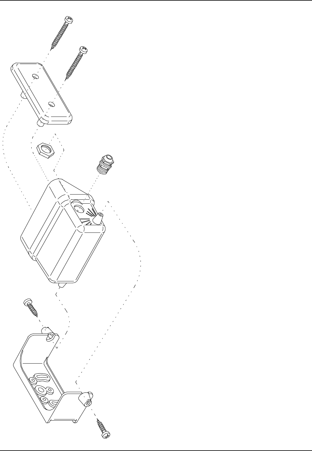
2.2 Mounting of the bracket
The bracket is suitable for both wall- and ceiling mounting. In case of ceiling mounting, it has to
be turned by 180° opposite the housing of the motion detector.
2.3 How to connect the motion detector
Connection is done as shown in figure 2. Deposit the leads of the flexible connecting cable
10 cm from the appliance, lead it through the lateral PG-screwing and fix it.
In case of DC power supply, polarity is insignificant.
10cm
2.4 How to screw down the housing
The cover should be screwed down with a torque of approx. 1 Nm. Put the cover evenly into the
groove of the housing and screw it down.
Attention! If the cover is tilt, for example due to squeezed cable leads in between the screw
guides, the tightness of the housing is not guaranteed!
MWD BF Instruction manual
608/02 FEIG ELECTRONIC GmbH
Figure 1: Magnified diagram of
the housing.
Instruction manual MWD BF
FEIG ELECTRONIC GmbH 08/02 7
3Adjustment and Initiation
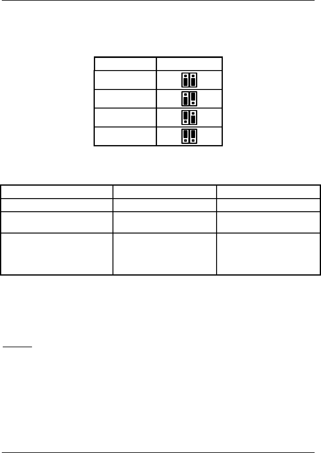
3.1 Direction identification
The direction identification device of the motion detector may be adjusted by the DIP-switches
located on the right side. DIP-switch No. 1 is assigned to approaching objects, which is
adjusted most often. If DIP-switch No. 2 is switched on, the device reacts to objects that are
departing from the motion detector. If both DIP-switches are switched on or off, the direction
identification is deactivated.
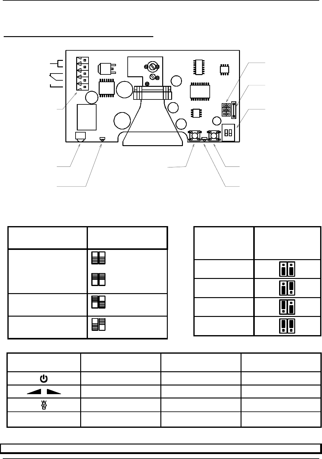
Direction
identification
DIP-switch
1 2
approaching 1 2
ON OFF
departure 1 2
OFF ON
off 1 2
OFF OFF
1 2
ON ON
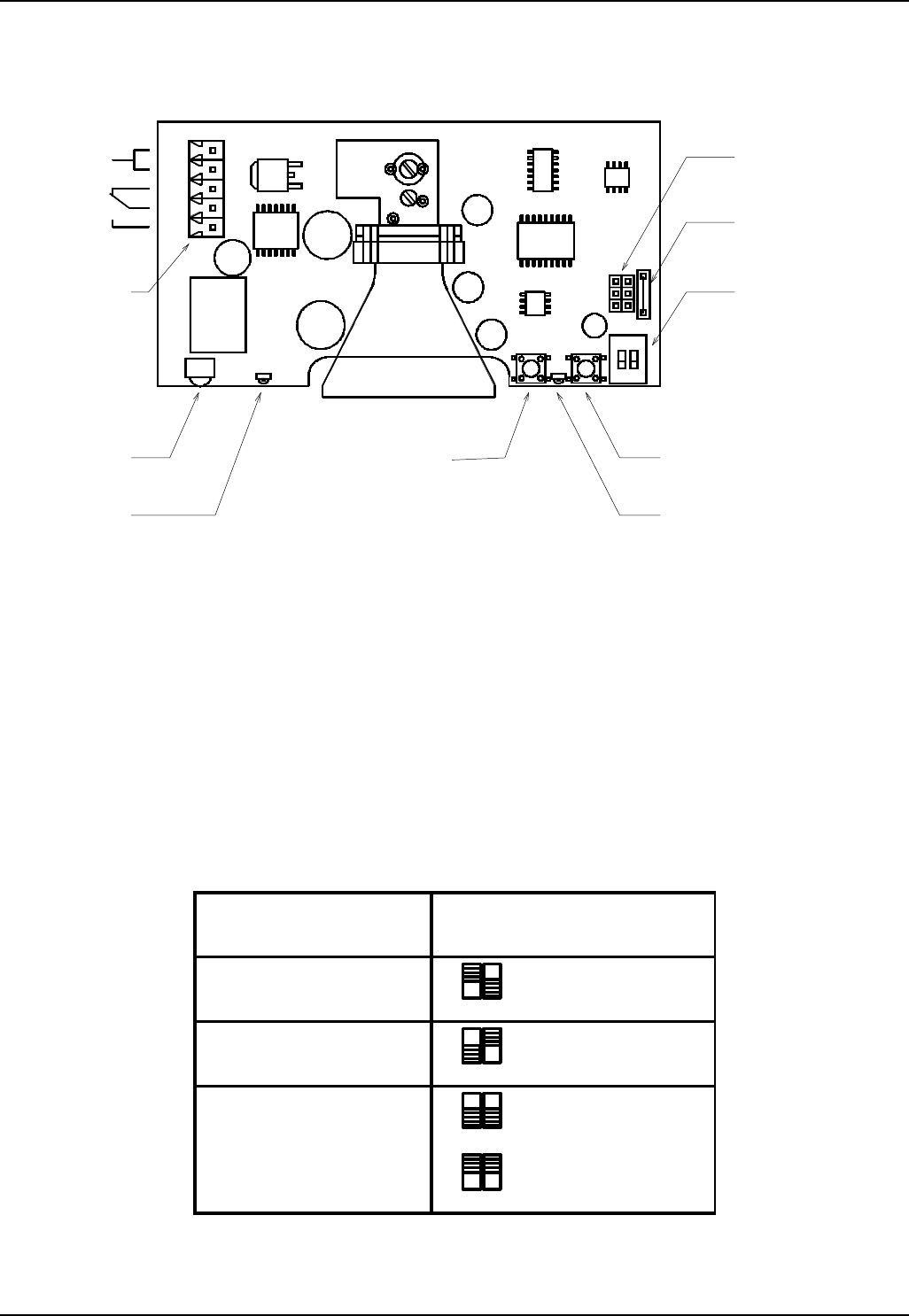
Button
a) Change function (short)
b) Exit input mode (long)
LED yellow
a) Ready to receive remote control
b) Flash signals function
IR-receiver
for remote control
Connector
12-27V AC
12-30V DC
~
~
DIP-Switch
Direction mode
ON
Button
a) Change value (short)
b) Exit input mode (long)
LED red
a) Object recognition normal mode
b) Flash signals device address
c) Flash signals current value
Jumper
Device address
Jumper/Resistor
Relay hold time
Figure 2: Operating elements on PCB
MWD BF Instruction manual
808/02 FEIG ELECTRONIC GmbH
3.2 Device address
In order to be able to adjust neighboring motion detectors with a remote control, an address
may be assigned to each device in the range of 1-4. For this purpose, a jumper field is located
above the DIP-switches.
Address Jumper position
1
2
3
4
3.3 LED display
Mode of operation Yellow LED – left side Red LED – right side
object recognition off object identified
adjustment with key button flash signals for function
numbers flash signals acc. to
parameter significance
adjustment with remote control a) ready to receive
infrared remote control
b) flash signals for function
numbers
a) flash signals acc. to
parameter significance
b) flash signals for device
address
3.4 Fall-delay time of relay
The factory-alignment for the fall-delay time of the relay is 0,5 seconds.
An extension of the fall-delay time to 2 seconds may be reached by removing the resistor which
is located next to the jumpers for the device address (figure 2).
Warning: The resistor may only be cut through in power off condition !
Please make sure that no components or strip conductors are damaged !
3.5 Personal suppression
If personal suppression is activated, the appearance of single persons will not trigger the
device. For more information regarding adjustment of personal suppression, please see section
3.6.2 resp. 3.7.3.
Personal suppression is designed for the use in typical internal traffic situations at a shed gate.
Deviating conditions (very low or high mounting height, setting angle is too steep or too flat,
oblique mounting position) or untypical objects (e.g. fast moving persons, groups, very slow

Instruction manual MWD BF
FEIG ELECTRONIC GmbH 08/02 9
vehicles, fork-lift trucks with fabric rolls etc.) may lead to malfunctions if personal suppression is
activated.
3.6 Adjustment with key buttons
Operational parameters (sensitivity, personal suppression) may be adjusted with the buttons
located at the right side of the horn antenna.
Left button / yellow LED: select/indicate function
Right button / red LED: change/indicate value
If a function is selected for the first time, the function number is indicated on the yellow LED ,
followed by the currently set value on the red LED.
The adjustment process is terminated automatically 30 seconds after the last button has been
pressed or by pressing a button for a longer time.
3.6.1 Selection of sensitivity
The sensitivity of the motion detector may be adjusted in the range of 1 to 15. Each time the
right button is pressed, the sensitivity is increased by one degree. Degree 15 is followed by
degree 1.
Yellow LED flashes 1x
Red LED flashes 1 x acc. to value of the current degree of sensitivity
3.6.2 Personal suppression
The personal suppression of the motion detector may be activated (position 1) and deactivated
(position 2) by using the button on the right side.
Yellow LED flashes 2x
LED rot flashes 1x if personal suppression is activated
2x if personal suppression is deactivated
3.6.3 Factory setting
In order to reset the parameters to the factory setting, both buttons are pressed while switching
on power supply. Now, the following adjustments are made:
Degree of sensitivity: 7
Personal suppression: off
3.7 Adjustments with the infrared remote control MWD RC
3.7.1 How to activate the adjustment mode
Before the parameters of a motion detector can be changed with the remote control, the device
has to be activated for this adjustment. For this purpose, please press the -key. Now, all
motion detectors within the range of reception of the remote control will indicate the set device
address on the red LED. If the address of the desired device is entered within 3 seconds by the
numeral keys of the remote control, the activated device shows its readiness for entry on the
yellow LED. All other devices are not activated and return to their normal mode.
MWD BF Instruction manual
10 08/02 FEIG ELECTRONIC GmbH
3.7.2 Selection of sensitivity
After the device has been cleared, the sensitivity of the motion detector may be changed with
the keys and . When the keys are pressed for the first time, the yellow LED indicates
the number of the desired function with flash signals. The adjusted value is indicated by flash
signals of the red LED. Sensitivity ranges from 1 to 15.
Yellow LED flashes 1x (function 1)
Red LED flashes 1 x acc. to value of current sensitivity level
Notice: Please switch off personal suppression when adjusting sensitivity.
3.7.3 Personal suppression
The -key changes the setting of the personal suppression.
Yellow LED flashes 2x (function 2)
Red LED flashes 1x if personal suppression is switched on
2x if personal suppression is switched off
3.7.4 How to terminate the adjustment mode
Adjustment with the remote control is terminated by pressing the -key. The motion detector
now returns to the normal detection mode. The yellow LED is extinguished. The red LED now
continues to indicate detected objects. The object recognition mode is automatically activated, if
no entry has been made with the key buttons or remote control for 30 seconds.
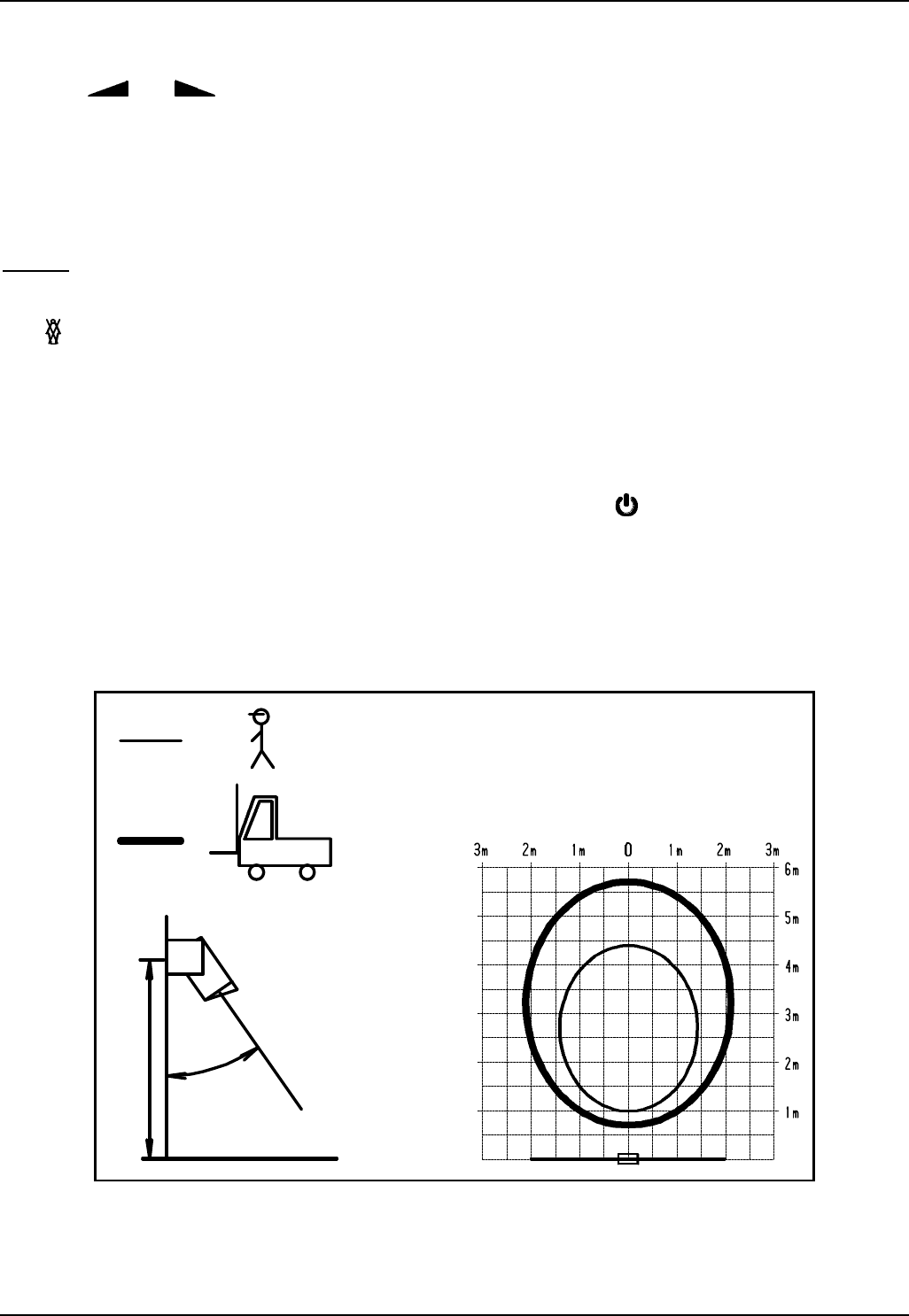
3.8 Adjustment of the detection zone
5m
30°
The MWD BF has a circular detection zone. Size and position of the detection zone may be
altered by adjusting sensitivity and inclination angle. In general, the optimum inclination angle
lies between 30° and 45°.

Instruction manual MWD BF
FEIG ELECTRONIC GmbH 08/02 11
In order to change the angle of radiation, please loosen the lateral screws located between
mounting bracket and housing. On both sides of the housing there are division marks in a 15°
grid system.
The size of the detection zone may change depending on the size and speed of the object to be
detected. If the motion detector is mounted in a height of more than 4 meters and sensitivity is
low, the detection zone for persons becomes very small.
3.9 Initiation procedure
•Sensitivity adjustment should always be done with the personal suppression mode being
switched off. If need be, the personal suppression mode may then be activated and the
function may be tested with a vehicle (v > 10km/h).
•The first attempts of putting the device into operation should be carried out with the opening
system of the downstream gate- or barrier system being switched off. The personal
suppression mode should be switched off as well.
•In order to test the device, please approach the motion detector from one point outside the
detection field and observe the reaction of the device by means of the LED. This test should
be carried out from all directions.
•With the help of the information gained by this test, the detection zone of the motion detector
may be changed by using the sensitivity adjustment.
•The gate- resp. barrier control may now be put into operation again. After that, one trial run
should be carried out with the gate operating. If the motion detector reacts to the movements
of the gate, the inclination angle to the gate has to be increased, until this effect may not be
noticed anymore.
•If need be, the size of the detection zone has to be readjusted by using sensitivity selection.
3.10 Possible reasons of malfunctions
•The reasons for malfunctions of the motion detector may be the following
- moving parts in the surrounding area,
- vibrations which are transmitted to the appliance through the mounting bracket,
- electric disturbances in the connecting cable
- or electric fields

MWD BF Instruction manual
12 08/02 FEIG ELECTRONIC GmbH
4Technical Data
Housing Dimensions (without cable) 132 x 155 x 58 mm
Color black
Housing plastic ASA
Mounting bracket plastic ASA
Cover plastic PC
Weight (incl. mounting bracket) 0,3 kg
Protective system IP 65
Supply voltage 12-27 V AC
12-30 V DC
Power consumption typ. 1,5 W
max. 2,4 W
Operating temperature -20 °C to +55 °C
Storing temperature -30 °C to +75 °C
Air moisture < 95 % non fogging
Frequency 24,125 GHz
Transmitting power typ. 5 mW
Output relay
max. turn-on voltage 24 V AC/DC
max. switching current 1 A at resistive load
min. switching current 1 mA
Contact type 1 change-over contact (potential-free)
In case of inductive load please provide for an external
protective wiring or the relay contacts !
Connecting cable Flexible, max. 5x1,0 qmm
Fall-delay time of relay 0,5 s / 2 s , selection with jumper
Maximum mounting height 6 m
Adjustable functions By means of sliding switch on printed card
Direction recognition
off/approaching/departure
By means of key button or infrared remote control
Sensitivity
Personal suppression
Factory setting (only key buttons)
Applicable standards
Radio approval
EMC
ETS 300 440
FCC CFR 47, Part 15 Subpart C, Section 15.245
ETS 300 683

Instruction manual MWD BF
FEIG ELECTRONIC GmbH 08/02 13
5Safety instructions
•This device shall only be used for the purpose intended by the manufacturer.
•The operating instructions have to be handed out to each user and accessible at any time.
•Improper changes and spare parts resp. special features which are not sold or
recommended by the manufacturer of the device may cause fires, electric shock and
injuries. Such measures therefore lead to nonliability of the manufacturer and no guarantee
will be given.
•For this device, the warranty regulations act applies in the version valid at the time of
purchase. We exclude liability for improper or wrong manual or automatic adjustment of
parameters resp. improper use of the appliance.
•Repair work should only be carried out by the manufacturer.
•Connection, initiation, maintenance, measuring and adjustment of the motion detector
should only be carried out by electrical engineers with accident prevention skills.
•When handling appliances which get into contact with electric current, VDE-rules have to be
observed - especially VDE 0100, VDE 0550/0551, VDE 0700, VDE 0711, VDE 0860, VDE
0105 as well as the fire – and accident prevention standard VBG4.
•Please switch off current supply prior to opening the device and make sure that it remains
off.
•If an indicator lamp goes out, this is not a proof that the device is without electricity and
disconnected from power supply. All work that is carried out at the device as well as
installation has to be carried out in conformance with the national electric regulations and
the local rules.
•The user has to make sure that the appliance is mounted and connected according to the
technical rules of the country of installation as well as other regional regulations. This
applies especially to cable dimensioning, protection, earthing, cutoff, disconnection, isolation
supervision and excess current cut-out.
•Low-voltage operation is not allowed at the relay outputs.
•According to machine rule 89/392/EWG, appendix IV, the device may not be used as a
safety component. In facilities with a high danger potential, additional safety devices are
necessary !
•The hard gold alloy of the relay contacts is destroyed if switching currents of more than 100
mA are used. Relays with such predamaged contacts may only switch currents of more than
100 mA reliably!
•If the place of operation is located in direct proximity to foil gates, suitable measures have to
be taken to branch off the electrostatic charging of the gate foil.

MWD BF Instruction manual
14 08/02 FEIG ELECTRONIC GmbH
6Type approval
Europe (CE)
When used according to regulation, this radio equipment conforms with the basic requirements
of article 3 and the other relevant provisions of the R&TTE guideline1999/5/EC dated March 99.

Instruction manual MWD BF
FEIG ELECTRONIC GmbH 08/02 15
USA (FCC)
FCC ID: PJMMWDBF
This device complies with part 15 of the FCC Rules. Operation is subject to the
following two conditions:
(1) This device may not cause harmful interference, and
(2) this device must accept any interference received, including interference that may
cause undesired operation.
Unauthorized modifications may void the authority granted under Federal
communications Commission Rules permitting the operation of this device.
MWD BF Instruction manual
16 08/02 FEIG ELECTRONIC GmbH
7Abstract
Operating elements and pin configuration:
Button
a) Change function (short)
b) Exit input mode (long)
LED yellow
a) Ready to receive remote control
b) Flash signals function
IR-receiver
for remote control
Connector
12-27V AC
12-30V DC ~
~
DIP-Switch
Direction mode
ON
Button
a) Change value (short)
b) Exit input mode (long)
LED red
a) Object recognition normal mode
b) Flash signals device address
c) Flash signals current value
Jumper
Device address
Jumper/Resistor
Relay hold time
Device address
for remote
control
Jumper
position
1
2
3
4
Remote control key Function Flash signal of LED
Left right Adjustment range
Activation Ready Address 1 .. 4 (address)
/Sensitivity 1x current value 1=low .. 15=high
personal suppression 2x current value 1=on 2=off
ii - - -
Direction
recognition
DIP-switches
1 2
Off 1 2
1 2
OFF OFF
ON ON
Approaching 1 2
ON OFF
Departure 1 2
OFF ON
FEIG ELECTRONIC GmbH * Germany * 35781 Weilburg * Lange Str. 4 * Tel.: +49/6471/3109-0 * Fax: +49/6471/3109-99