Firefly RFID Solutions FFP466M12P1 Firefly RFID Expansion Card User Manual VER 551 11UMx
Firefly RFID Solutions Inc. Firefly RFID Expansion Card VER 551 11UMx
Contents
- 1. User Manual
- 2. User Manaul
User Manual

Copyright 2013
Firefly RFID Solutions, Inc.
Page 1 of 16
www.FireflyRFID.com
1521 Boone Trail Road, Sanford NC 27330
User’s Manual
Integrated 1W UHF pRFID Reader for Psion Workabout
V
ER
-
551
-
11UMV2
1
5
-
M
a
y
-
2013
Integrated 1W UHF pRFID Reader
for Psion Workabout
User’s Manual
Document ID: VER-551-11UM
Version 2.0
Owner: BCS Solutions, Inc.
Author: Bill Davidson
Issued: 1-March-2013
Updated: 15-May-2013
By:
Firefly RFID Solutions, Inc.
Division of BCS Solutions Inc.
1521 Boone Trail Road
Sanford, North Carolina USA 27330
Phone: +1 (919) 460-1177
Fax: +1 (919) 460-1179
www.RFIDresolution.com
Customer
Verdasee
Date:
Sales and Marketing:
N/A
Date:
Technical:
Bill Davidson
Date:
15-May-2013

Copyright 2013
Firefly RFID Solutions, Inc.
Page 2 of 16
www.FireflyRFID.com
1521 Boone Trail Road, Sanford NC 27330
Integrated 1W UHF pRFID Reader for Psion Workabout
V
ER
-
551
-
11UMV2
1
5
-
M
a
y
-
2013
FCC Notice
FCC ID: SD8FFP466M12P1
This equipment has been tested and found to comply with the limits for a Class B digital device,
pursuant to part 15 of the FCC Rules. Operation is
subject to
the following two conditions: (1) this
device may not cause interference, and (2) this device must accept any interference, including
interference that may cause undesired operation of the device.These limits are designed to
provide reasonable protection against harmful interference in a residential installation. This
equipment generates uses and can radiate radio frequency energy and, if not installed and used
in accordance with the instructions, may cause harmful interference to radio communications.
However, there is no guarantee that interference will not occur in a particular installation. If this
equipment does cause harmful interference to radio or television reception, which can be
determined by turning the equipment off and on, the user is encouraged to try to correct the
interference by one or more of the following measures:
•
Reorient or relocate the receiving antenna.
•
Increase the separation between the equipment and receiver.
•
Connect the equipment into an outlet on a circuit different from that to which the receiver
is connected.
•
Consult the dealer or an experienced radio/TV technician for help.
Warning: Modifications not approved by the responsible party could void the
user’s authority to operate this equipment.
IC Notice
IC ID: 10968A-FFP466M12P1
This device complies with Industry Canada licence-exempt RSS standard(s). Operation is
subject
to
the following two conditions: (1) this device may not cause interference, and (2) this device
must accept any interference, including interference that may cause undesired operation of the
device.
Le présent appareil est conforme aux CNR d'Industrie Canada applicables aux appareils radio
exempts de licence. L'exploitation est autorisée aux deux conditions suivantes : (1) l'appareil ne
doit pas produire de brouillage, et (2) l'utilisateur de l'appareil doit accepter tout brouillage
radioélectrique subi, même si le brouillage est susceptible d'en compromettre le
fonctionnement.
Under Industry Canada regulations, this radio transmitter may only operate using an antenna of
a type and maximum (or lesser) gain approved for the transmitter by Industry Canada. To reduce
potential radio interference to other users, the antenna type and its gain should be so chosen
that the equivalent isotropically radiated power (e.i.r.p.) is not more than that necessary for
successful communication.
Conformément à la réglementation d'Industrie Canada, le présent émetteur radio peut
fonctionner avec une antenne d'un type et d'un gain maximal (ou inférieur) approuvé pour
l'émetteur par Industrie Canada. Dans le but de réduire les risques de brouillage radioélectrique
à l'intention des autres utilisateurs, il faut choisir le type d'antenne et son gain de sorte que la
puissance isotrope rayonnée équivalente (p.i.r.e.) ne dépasse pas l'intensité nécessaire à
l'établissement d'une communication satisfaisante.

Copyright 2013
Firefly RFID Solutions, Inc.
Page 3 of 16
www.FireflyRFID.com
1521 Boone Trail Road, Sanford NC 27330
Integrated 1W UHF pRFID Reader for Psion Workabout
V
ER
-
551
-
11UMV2
1
5
-
M
a
y
-
2013
Exposure
to
RF
Energy
THIS MODEL DEVICE MEETS U.S. AND INTERNATIONAL REQUIREMENTS FOR EXPOSURE
TO RADIO FREQUENCY RADIATION.
The VER-551-11 is a radio transmitter and receiver module. It is designed and manufactured not to
exceed the emission limits for exposure to radio frequency (RF) energy set by the Federal
Communications Commission of the U.S. Government and by the International Commission on
Non-Ionizing Radiation Protection (ICNIRP). The device also meets the European Radio and
Telecommunications Terminal Equipment (R&TTE) directive, for protecting the health and safety of
the user and other persons.
These limits are part of comprehensive guidelines that establish permitted levels of RF energy for
the general population. The guidelines are based on standards that were developed by
independent scientific organizations through periodic and thorough evaluation of scientific studies.
The standards include a substantial safety margin designed to assure the safety of all persons,
regardless of age and health.
Before a device model is available for sale to the public, it must be tested and certified to operate
within the limits for safe exposure established by the FCC and international organizations. The tests
are performed in positions and locations (e.g., next to the body) as required by the FCC for each
model. The FCC has granted an Equipment Authorization for this model device with all reported
SAR levels (see below) evaluated as in compliance with the FCC RF emission guidelines.
This device meets RF exposure guidelines when the antennas are positioned at a minimum
distance from the body. In order to transmit data or messages, this device requires a quality
connection to the RFID tag devices. In some cases, transmission of data or messages may be
delayed until such a connection becomes available. Be sure that the recommended distance is
observed until the transmission is complete.
The exposure standard for wireless devices employs a unit of measurement known as the Specific
Absorption Rate, or SAR. Tests for SAR are conducted using standard operating positions specified
by the FCC with the device transmitting at its highest certified power level in all tested frequency
bands. The SAR limit set by the FCC is 1.6 W/kg. The international guidelines state that the SAR
limit for mobile devices used by the public is 2.0 W/kg averaged over 10 grams of body tissue. SAR
values may vary depending on national reporting requirements and the network band. Although the
SAR is determined at the highest certified power level, the actual SAR level of the device while
operating can be well below the maximum value because the device operates at multiple power
levels and at a low duty cycle based on the number of RFID tag devices it is currently
communicating with.
SAR information on this model device is on file with the FCC and can be found under the Display
Grant section and http://www.fcc.gov/oet/fccid after searching on FCC ID: SD8FFP466M12P1 and
IC: 10968A-FFP466M12P1.

Copyright 2013
Firefly RFID Solutions, Inc.
Page 4 of 16
www.FireflyRFID.com
1521 Boone Trail Road, Sanford NC 27330
Integrated 1W UHF pRFID Reader for Psion Workabout
V
ER
-
551
-
11UMV2
1
5
-
M
a
y
-
2013
Contents
1 Overview ........................................................................................................................ 5
1.1 Installation ........................................................................................................................ 5
1.2 Module Verification ......................................................................................................... 6
2 Module Operation ......................................................................................................... 8
2.1 Module Command Channel ............................................................................................ 8
2.2 pRFID passive RFID subsystem ..................................................................................... 9
2.3 a433 active RFID subsystem ......................................................................................... 11
3 Applications on the Module ........................................................................................ 13
3.1 Developing on a Handheld ............................................................................................ 13
3.2 Developing on a PC ........................................................................................................ 14
3.2.1
Putty Serial Connection ............................................................................................................ 14
3.2.2
JTAG Connector ....................................................................................................................... 15
4 Revision History .......................................................................................................... 16

Copyright 2013
Firefly RFID Solutions, Inc.
Page 5 of 16
www.FireflyRFID.com
1521 Boone Trail Road, Sanford NC 27330
Integrated 1W UHF pRFID Reader for Psion Workabout
V
ER
-
551
-
11UMV2
1
5
-
M
a
y
-
2013

Copyright 2013
Firefly RFID Solutions, Inc.
Page 6 of 16
www.FireflyRFID.com
1521 Boone Trail Road, Sanford NC 27330
Integrated 1W UHF pRFID Reader for Psion Workabout
V
ER
-
551
-
11UMV2
1
5
-
M
a
y
-
2013
1.2 Module Verification
The module performs a self check whenever power is applied and whenever the module
enable pin changes from off to on. The results of this self-check are immediately
presented on the serial interface to the host device. The results can also be querried by
the host device at anytime by issuing a status request command over that serial interface.
The micro-controller serial interface is always available when power is provided over the
interface connector, even if the module enable pin is off. The radio functions however
will not operate unless this enable pin is on. Since this module can fit in different host
devices, the enable pin can be configured at time of installation to be active high, low or
don’t care with serial interface on/off commands required. The status can be verified
without having to enable the module.
It is a function of the host device’s human interface to alert the user of a problem with the
status. It is important to note however that the firmware within the module will not
allow any operation that the self check has shown to be unavailable, such as requesting
operation over an antenna port that is showing faulty/missing antenna status or
requesting operation when there are insufficient power levels to execute the operation.
On the very first power up, the module will output the two non XML format lines over
the serial interface which identifies the master firmware on the module and the module’s
hardware version including the board manufacturer’s identification.
VER-551-11Sx1.7 2/26/2013
VER-551-11Hx1.1 2812-475 1007624-5
From this point on, all serial line communications in either direction will be in an XML
format. The module does a self check then puts out a status report on the current state.
The following would be a typical example;
<Status state="RST" fmwr="VER-551-11Sx1.7 2/26/2013" hdwr="VER-551-11Hx1.1 2812-475
1007624-5" a433="000004" PWR="300" ANT="43-1" Vcap="3.72" Vsup="3.72" seq="000001"/>
state
=
"
RST
"
Indicates the module is starting operation from
h
a
rd
RESET, which could be power
up, power glitch or watchdog timer.
f
mwr
=
"
VER
-
551
-
11S…
"
Gives the master firmware for the module. The version and date shown in the above
example above is that which went through compliance testing.
hdwr
=
"
VER
-
551
-
11H…
"
Gives the module’s hardware version and manufacture information. The vers
ion
shown in the above example above is that which went through compliance testing.
a433
=
"
000004
"
Gives the version number of the 433 MHz transceiver used for the ‘active’ telemetry
channel.
ANT
=
"
43
-
1
"
Indicates that antenna ports 4, 3 and 1 on the passi
ve RFID reader radio are properly
connected to an antenna. There is a problem with port 2, either the antenna is not
connected or there is a problem with the cable or connectors. In anycase it means
any passive RFID operations will be restricted to ports 4, 3 and 1.
Vcap
=
"
2
.
97
"
Indicates power level available for operation of the radios. This read the same value
as Vsup when fully ready for operation. At power up as in this case or after high
power operations, it will read lower than Vsup and then build up to Vsup.
Operation is suspended unit this value builds up to a level that can support the
requested operation.
Vsup
=
"
3.72
"
Indicates voltage level of power supply to the module
provided over the interface
connector. Typically this is the battery level in a handheld or portable device.
seq
=
"
00001
"
Indicates the very first operation after a hard reset.

Copyright 2013
Firefly RFID Solutions, Inc.
Page 7 of 16
www.FireflyRFID.com
1521 Boone Trail Road, Sanford NC 27330
Integrated 1W UHF pRFID Reader for Psion Workabout
V
ER
-
551
-
11UMV2
1
5
-
M
a
y
-
2013
The above table shows the important fields on the startup status which indicate the
device has been properly installed. The fact that the message comes up at all indicates
there is power and the module is functioning. The version levels will give compatibility
information for the application. The antenna information is important to gain data about
the configuration whether intentional or error/damage during installation. The voltage
levels give battery condition and indication of whether there is enough power to operate.
very first power up, the module will output the two non XML format lines over the serial
interface which identifies the master firmware on the module and the module’s hardware
version including the board manufacturer’s identification.
Copyright 2013
Firefly RFID Solutions, Inc.
Page 8 of 16
www.FireflyRFID.com
1521 Boone Trail Road, Sanford NC 27330
Integrated 1W UHF pRFID Reader for Psion Workabout
V
ER
-
551
-
11UMV2
1
5
-
M
a
y
-
2013
Workabout Pro Internal Connector
SPI
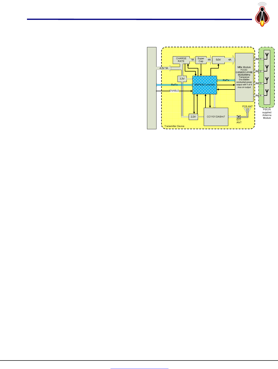
2 Module Operation
The block diagram at right gives the
general architecture of this module. There
are three major components; the passive
915 MHz RFID reader, the active RFID
433 MHz reader (DASH-7 in diagram)
and the power management system. The
power management system handles all
communications to the host device
(Workabout Pro in diagram at right) and
controls all operations of the other two
components. It converts commands from
the host into the appropriate actions
keeping the module working within
specification and withoperating conditions.
2.1 Module Command Channel
All module command and control is through the serial port on the host interface
connector with the exception of the enable hardware line which can be configured at time
of installation to enable or disable the radio functions in the module. The commands are
in an XML format, typically with multiple attributres and no elements. The ‘XML TAG’
identifies the destination as the passive 915 MHz RFID radio, the 433 MHz radio or the
power management system. The ‘XML ATTRIBUTE(S)’ defines the actions required. The
four possible ‘XML TAG’s or destinations are;
• pRFID - Passive RFID reader only actions / parameters,
• a433 - Active 433MHz telemetry only actions / parameters,
• ALL - Actions / Parametrs affect both radio subsystems,
• MAINT - Maintenance actions and parameters.
For example the pRFID:pwr attribute is a separate attribute from the a433:pwr attribute,
and ALL:pwr sets both the pRFID:pwr and a433:pwr to that same value or to the
maximum/minimum for the function that best matches the requested power.
<pRFID pwr="300"/> Sets passive RFID 915 MHz power to 300 deci-dBm (30.0 dBm)
<a433 pwr="75"/> Sets active RFID 433 MHz power to 75 deci-dBm (7.5 dBm)
<ALL pwr="300"/> Sets passive radio to 30.0 dBm and active radio to 10.0 dBm
These commands can have multiple attributes so that;
<pRFID pwr="300" ant="31"/> is equivalent to issueing the following two commands;
<pRFID pwr="300"/>
<pRFID ant="31"/>
The above commands will configure the passive 915 MHz RFID reader to use only
antenna port 1 and antenna port 3 at a power level of 30.0 dBm. The reader will remain
in this configuration until those attributes are changed.
The module will respond as appropriate to the command as described in the sections
bellow or with a <NAK /> if it cannot decode the command.

Copyright 2013
Firefly RFID Solutions, Inc.
Page 9 of 16
www.FireflyRFID.com
1521 Boone Trail Road, Sanford NC 27330
Integrated 1W UHF pRFID Reader for Psion Workabout
V
ER
-
551
-
11UMV2
1
5
-
M
a
y
-
2013
2.2 pRFID passive RFID subsystem
The passive RFID reader subsystem commands are of the following general format;
<pRFID cmd="MR" ant="1234" pwr="300" rpt="1" dur="250" dc="50" fields="oid+cnt+ant"/>
The above command, which is a read request on antenna ports 1,2,3 and 4 at full 30.0
dBm power reporting back oid, count and antennae, might give the following response
of a tag read if that tag was in view of the module’s port 2 and port 3 antennae.
<tag STS="RAW" OID="20120225D655020001020019" CNT="12" ANT="23" />
Note here that the ‘xml tag’ pRFID identifies this as an action to be taken by the passive
RFID reader. The on-board power management system decodes this command into the
required actions based on power availability and forwards the appropriate commands to
a 1 watt UHF M6e radio.
The <pRFID />attributes are optional. Those attributes required for the requested action
are based on;
1. Attributes in the command string, such as pwr="300" in the above example
2. If not in command, then use last setting of the missing attributes.
<pRFID cmd="MR"/> (Issued after the above example repeats the same command)
3. If not in command and not previously set, missing attributres use the default
values as described below.
The one exception is the cmd attribute which if not specified will cause the unit to return
version numbers and configuration for the module. The attributes have the following
effect;
• cmd default - if not specified, unit returns version and configuration
o cmd="MR" specifies unit to do a multiple scans for tags on the each of the
specified antennae for the specified duration of continuous power at the
specified power level with the whole operation being run the specified
repeat number of times. The repeat rate being governed by the specified
duty cycle and the amount of power available according to the power
management system.
o cmd="CR" specifies unit to do a continuous scans for tags on the each of
the specified antennae for the specified duration of continuous power at
the specified power level with the whole operation being repeated
continuously. The routine will continue to run until the abort command
or until power levels are too low to reliably continue operations. As
above, the repeat rate being governed by the specified duty cycle and the
amount of power available according to the power management system.
o cmd="AB" specifies unit to abort all reader operations. This includes
continuous reads or multiple read operations.
o cmd="ON" same effect as the Psion’s hardware line. It overrides that
control line and will turn on the reader.
o cmd="OFF" intended to turn off the reader if ther Psion control line is not
being used, however if that control line is set to enable the reader that
will override this command.

Copyright 2013
Firefly RFID Solutions, Inc.
Page 10 of 16
www.FireflyRFID.com
1521 Boone Trail Road, Sanford NC 27330
Integrated 1W UHF pRFID Reader for Psion Workabout
V
ER
-
551
-
11UMV2
1
5
-
M
a
y
-
2013
o cmd="LT" Lists all tags in the buffer since the last LT command was
issued. It packages the tag reads into a
• ant default ant="12" This attribute is a string of up to 10 characters which
specifies the antennae to be used in the scan and their sequence. For example an
attribute of ant="121314" would specify starting the scan on antenna 1 then
scanning antenna 2 then antenna 1 again then antenna 3 and so on. In this
manner one can bias the scan to specific antenna elements as required by the
application. The above example having a heavy bias in favor of antenna 1.
• pwr default pwr="300". This attribute is a number from 1 to 300 and
represents the rf conducted power used for the reading in tenths of dBm. The
maximum is 300 and represents 30.0 dBm or 1 watt conducted power.
• rpt default rpt="1". This attribute is a number from 1 to 250 and represents
the number of time the scan sequence through all the specified antennaes is
repeated.
• dur default dur="250". This attribute is a number from 1 to 1000 and
represents minimum time in milliSeconds that the reader will stay scanning on
each of the specied antennae.
• dc default dc="30". This attribute is a number from 1 to 100 and represents
the duty cycle in percentage points for operating the reader. The reader shuts
down between successive read scans to save power. This factor basically
determines how long that shutdown is based on usage in a scan sequence. A dc =
30 with dur = 300 would give a read of 300 mS every second. This number is a
goal and may be overridden based on power and battery conditions.
• baud default baud="115200". This attribute can be one of the following rates;
{ 460800, 230400, 115200, 57600, 38400, 9600, 4800, 2400, 1200 }.
This routine only looks at the first three significant digits to set one of the above
fixed baud rates, so using baud=115900 would end up setting the baud rate to
115,200 however setting a baud rate to baud=9643 would be unrecognizable and
would end up not changing baud rate since the current rate is communicating.
• fields default fields="oid+ant". This attribute is a collection of field names
separated by ‘+’, or any white space and specifies the attributes that are returned
with each tag read. The valid field names are;
o oid This value is the tag’s OID, typically 96 bit EPC number,
o ant This value is antenna that the read was made on,
o pwr This value is the conducted power used for the read..
o cnt This value is number of times the tag was read during the scan.
o rssi This value is the receive signal strength for the read.
o bat This value is the battery voltage after read.
o seq This value is an incrementing sequence number .

Copyright 2013
Firefly RFID Solutions, Inc.
Page 11 of 16
www.FireflyRFID.com
1521 Boone Trail Road, Sanford NC 27330
Integrated 1W UHF pRFID Reader for Psion Workabout
V
ER
-
551
-
11UMV2
1
5
-
M
a
y
-
2013
2.3 a433 active RFID subsystem
The active RFID reader subsystem is more of a peer to peer type communications and
could actually be viewed as a telemetry channel. Indeed the system would not know that
it is talking to an active tag or another tag reader other than by the data content over the
protocol. This channel can then be used as a bridge between different types of readers, or
to a remote access link. The commands are of exactly the same format as for the passive
RFID subsystem other than the defaults and limits.
<a433 cmd="MR" ant="1234" pwr="300" rpt="1" dur="250" dc="50" fields="oid+cnt+ant"/>
The above command, which is identical to the pRFID example above would also execute
a read request but ignore the ant attribute as that subsystem can only use the PCB
antenna integral to the module. The power level would be 10.0 dBm as that is the
maximum power level available on that subsystem. It would report back oid, count and
antenna and might give the following response of a tag read if that tag was in range of
the module. Note if requested the ant field will always respond back as 0 for this
subsystem to indicate the integral PCB antenna.
<tag STS="RAW" OID="20120225D655020001020019" CNT="12" ANT="0" />
As with the 915 MHz reader, <a433 />attributes are optional. Those attributes required
for the requested action are based on;
4. Attributes in the command string, such as pwr="300" in the above example
5. If not in command, then use last setting of the missing attributes.
<p433 cmd="MR"/> (Issued after the above example repeats the same command)
6. If not in command and not previously set, missing attributres use the default
values as described below.
The one exception is the cmd attribute which if not specified will cause the unit to return
version numbers and configuration for the module. The attributes have the following
effect;
• cmd default - if not specified, unit returns version and configuration
o cmd="MR" specifies unit to do a multiple scans for tags on the each of the
specified antennae for the specified duration of continuous power at the
specified power level with the whole operation being run the specified
repeat number of times. The repeat rate being governed by the specified
duty cycle and the amount of power available according to the power
management system.
o cmd="CR" specifies unit to do a continuous scans for tags on the each of
the specified antennae for the specified duration of continuous power at
the specified power level with the whole operation being repeated
continuously. The routine will continue to run until the abort command
or until power levels are too low to reliably continue operations. As
above, the repeat rate being governed by the specified duty cycle and the
amount of power available according to the power management system.
o cmd="AB" specifies unit to abort all reader operations. This includes
continuous reads or multiple read operations.
o cmd="ON" same effect as the Psion’s hardware line. It overrides that
control line and will turn on the reader.

Copyright 2013
Firefly RFID Solutions, Inc.
Page 12 of 16
www.FireflyRFID.com
1521 Boone Trail Road, Sanford NC 27330
Integrated 1W UHF pRFID Reader for Psion Workabout
V
ER
-
551
-
11UMV2
1
5
-
M
a
y
-
2013
o cmd="OFF" intended to turn off the reader if ther Psion control line is not
being used, however if that control line is set to enable the reader that
will override this command.
o cmd="LT" Lists all tags in the buffer since the last LT command was
issued. It packages the tag reads into a
• pwr default pwr="100". This attribute is a number from 1 to 100 and
represents the rf conducted power used for the reading in tenths of dBm. The
maximum is 100 and represents 10.0 dBm or 10 milliWatts conducted power.
• rpt default rpt="1". This attribute is a number from 1 to 250 and represents
the number of time the scan sequence through all the specified antennaes is
repeated.
• dur default dur="250". This attribute is a number from 1 to 1000 and
represents minimum time in milliSeconds that the reader will stay scanning on
each of the specied antennae.
• dc default dc="30". This attribute is a number from 1 to 100 and represents
the duty cycle in percentage points for operating the reader. The reader shuts
down between successive read scans to save power. This factor basically
determines how long that shutdown is based on usage in a scan sequence. A dc =
30 with dur = 300 would give a read of 300 mS every second. This number is a
goal and may be overridden based on power and battery conditions.
• baud default baud="115200". This attribute can be one of the following rates;
{ 460800, 230400, 115200, 57600, 38400, 9600, 4800, 2400, 1200 }.
This routine only looks at the first three significant digits to set one of the above
fixed baud rates, so using baud=115900 would end up setting the baud rate to
115,200 however setting a baud rate to baud=9643 would be unrecognizable and
would end up not changing baud rate since the current rate is communicating.
• fields default fields="oid+ant". This attribute is a collection of field names
separated by ‘+’, or any white space and specifies the attributes that are returned
with each tag read. The valid field names are;
o oid This value is the tag’s OID, typically 96 bit EPC number,
o ant This value always returns a 0 indicating the read was made on a433,
o pwr This value is the conducted power used for the read..
o cnt This value is number of times the tag was read during the scan.
o rssi This value is the receive signal strength for the read.
o bat This value is the battery voltage after read.
o seq This value is an incrementing sequence number .
Copyright 2013
Firefly RFID Solutions, Inc.
Page 13 of 16
www.FireflyRFID.com
1521 Boone Trail Road, Sanford NC 27330
Integrated 1W UHF pRFID Reader for Psion Workabout
V
ER
-
551
-
11UMV2
1
5
-
M
a
y
-
2013
3 Applications on the Module
3.1 Developing on a Handheld
This host handheld terminal itself is all that is required to operate this module. The
handheld terminal provides power and the pRFID antennae and by definition
provides a human interface capability. The module would normally be controlled by
an application program running on this handheld terminal, so the user functions
would therefore be defined by that application. Note that since the radios on the
module are controlled by the module’s firmware, power monitoring and self check
functions, the application developer does not have to worry about low level control
and perhaps operating the radios outside of certification limits or protocol
specifications.
In developing an application program one can still try command sequences to verify
operation using a terminal emulation program. Since all commands and responses
are in a human readable XML format, it makes this fairly easy to manually enter the
commands and read the responses. The Psion Workabout Pro comes with a serial
test program called ‘Serial Demo’ which can be used as a crude terminal emulation
program. The total equipment required to develop an application or run the module
would therefore be;
1. Handheld Terminal – Psion Workabout-Pro.
2. Terminal emulator software such as Psion’s “Serial Demo” program.
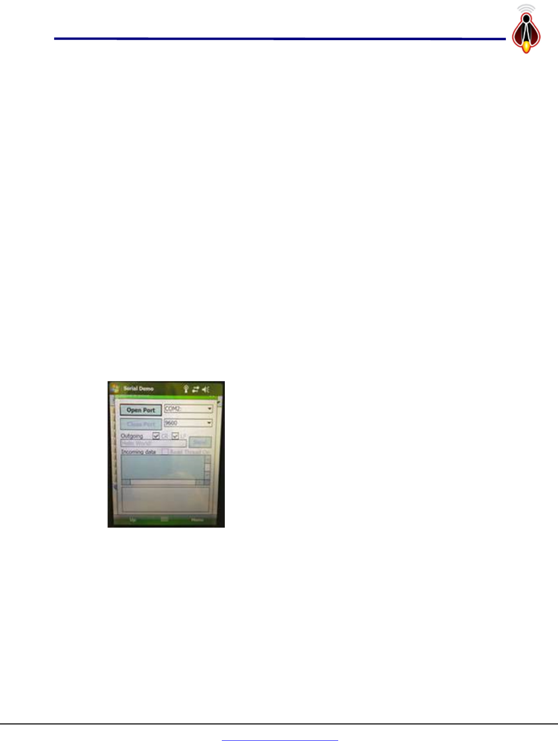
The handheld terminal must be turned on then use the
‘File Explorer’ to navigate to the location of the Serial
Demo software folder. Double click Serial Demo
executeable to start the program which will give direct
access to the command inputs for the Transmitter
Device module.
The program should start up with the screen as shown
at left. Reset the com port to COM1: and the baud to
115200 using the list selector – note the scroll bar on the
list for each one. Once these have been selected, click
the ‘Open Port’ button. The outgoing text box which
initially will show ‘Hello World!’ is the command string to the Transmitter Device
module.
The outgoing text has the full XML command set interpreter that is used to control
and use the Transmitter Device module in a software application. However, a
number of shortcut commands have been implemented to make this process easier
for testing using this simple serial demo program. Note that to send the command
to the Transmitter Device module one must click the ‘send’ button, using the
ENTER key does not send the command.
Copyright 2013
Firefly RFID Solutions, Inc.
Page 14 of 16
www.FireflyRFID.com
1521 Boone Trail Road, Sanford NC 27330
Integrated 1W UHF pRFID Reader for Psion Workabout
V
ER
-
551
-
11UMV2
1
5
-
M
a
y
-
2013
3.2 Developing on a PC
Alternately, the transmitter device can be tested in a stand-alone mode through the
JTAG connector that is used to program the device. In that case power needs to be
supplied and there is a serial console port connection through the JTAG connector to
allow the same control of the device as if it were in the handheld terminal. In the
following configuration the application could directly be developed on a more
feature rich PC platform before being ported over to a handheld device.
1. Power supply, 3-5V minimum 1amp capability.
2. External cable with MMCX connector for antenna or test device.
3. Laptop Computer with serial port capability
4. RS232-to-TTL (3.3V) converter
5. Terminal emulator software such as freeware program “PUTTY”.
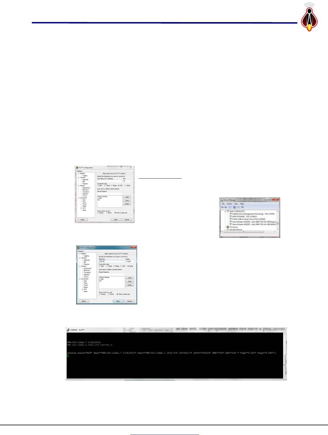
3.2.1 Putty Serial Connection
Putty is freeware that can be downloaded from
www.putty.org.
It will startup with defaults as shown
at the left. The program does not have a pull down
menu that shows the serial ports available for
connection. One way to
determine which ports are
which especially with USB
based serial ports if to run
the ‘Device Manager’. In this case we can see that
our serial port is COM 19.
One can then use this information to fill out putty
configuration screen first selecting the ‘Serial’ button
under the Connection Type then entering ‘COM19’ for
the serial line and 115200 for the speed as shown at
left. One can also save the session for faster starts at a
later time and recording the sessions.
Pressing the open button will then open a dialogue
screen which should look as follows as the module powers up.

Copyright 2013
Firefly RFID Solutions, Inc.
Page 15 of 16
www.FireflyRFID.com
1521 Boone Trail Road, Sanford NC 27330
Integrated 1W UHF pRFID Reader for Psion Workabout
V
ER
-
551
-
11UMV2
1
5
-
M
a
y
-
2013
3.2.2 JTAG Connector
The hardware connections to run the device in a standalone configuration are through
the JTAG programming connections shown below. The required connections are
shown in red. There are also three test point connections available on this connector to
aid in developing and debugging applications.
Header
0.1” 2x7
JTAG
Signal
MSP
pin
Description
1
TDO 92 PJ.0/TDO Test Data Output port
2
Vcc
3
TDI 93 PJ.1/TDI/CLK Test Data Input port
4
Vcc Ext Power Supply 4V, 1A
5
TMS 94 PJ.2/TMS Test Mode Select
6
KEY KEY KEY
7
TCK 95 PJ.3/TCK Test Clock
8
Test 91 TEST/SBWTCK Test Mode pin – select JTAG pins
9
GND Power Supply Ground
10
N/C 17 Scope test point 0
11
RST 96 RST/NMI/SBWTDIO Reset input active low
12
N/C 18 Scope test point 1
13
N/C 72 TxD for External debug/console link
14
N/C 73 RxD for External debug/console link

Copyright 2013
Firefly RFID Solutions, Inc.
Page 16 of 16
www.FireflyRFID.com
1521 Boone Trail Road, Sanford NC 27330
Integrated 1W UHF pRFID Reader for Psion Workabout
V
ER
-
551
-
11UMV2
1
5
-
M
a
y
-
2013
4 Revision History
Author Date Modification Telephone Number
Bill Davidson March-1, 2013
April-5, 2013
May-15, 2013
Initial entry and formatting
Assigned version V1.0 (SVN)
V2.0 add SAR warning label
919-460-1177
COPYRIGHT NOTICE
Copyright © 2013 by Firefly RFID Solutions, LLC. All rights are reserved.
No part of this document may be reproduced, transmitted, processed or recorded by any means or form, electronic,
mechanical, photographic or otherwise, translated to another language, or be released to any third party without the
express written consent of Firefly RFID Solutions, LLC
Printed in the United States of America