First Computer A440 NOTEBOOK COMPUTER User Manual A440 English Manual PDF
First International Computer Inc NOTEBOOK COMPUTER A440 English Manual PDF
Contents
- 1. user manual 1 of 2
- 2. user manual 2 of 2
user manual 1 of 2

Notebook User Guide
1
Copyright©2000
All Rights Reserved - Printed in Taiwan
Notebook Computer User Guide
Original Issue: 2000/9
This manual guides you in setting up and using your new notebook computer.
Information in this manual has been carefully checked for accuracy and is
subject to change without notice.
No part of this manual may be reproduced, stored in a retrieval system, or
transmitted, in any form or by any means, electronic, mechanical, photocopy,
recording, or otherwise, without prior written permission.
Trademarks
Product names used herein are for identification purposes only and may be
the trademarks of their respective companies.
IBM, AT, PS/2, and Token Ring are registered trademarks and OS/2 is a
trademark of International Business Machines Corporation.
Microsoft, MS-DOS, Windows, and Windows Sound System are trademarks
of Microsoft Corporation.
Intel and Intel Pentium is a registered trademark of Intel Corporation.
Sound Blaster, Sound Blaster Pro are trademarks of Creative Technology.
All other brands or product names mentioned in this manual are trademarks
or registered trademarks of their respective companies.

Notebook User Guide
2
FCC Information to User
Safety and Care Instructions
No matter what your level of experience with computers, please make sure
you read the safety and care instructions. This information can help protect
you and your computer from possible harm.
Radio and television interference
Warning: Use the specified shielded power cord and shielded signal cables
with this computer, so as not to interfere with radio and television reception.
If you use other cables, it may cause interference with radio and television
reception.
This equipment has been tested and found to comply with the limits for a
Class B digital device, pursuant to Part 15 of the FCC Rules. These limits are
designed to provide reasonable protection against harmful interference in a
residential installation. This equipment generates, uses and can radiate radio
frequency energy and, if not installed and used in accordance with the
instructions, may cause harmful interference to radio communications.
However, there is no guarantee that interference will not occur in a particular
installation. If this equipment does not cause harmful interference to radio or
television reception, which can be determined by turning the equipment off
and on, the user is encourage to try to correct the interference by one or more
of the following measures:
• Reorient or relocate the receiving antenna
• Increase the separation between the device and receiver
• Connect the device into an outlet on a circuit different from that to
which the receiver is connected.
• Consult the dealer or an experienced radio/television technician for help.

Notebook User Guide
3
You may find helpful the following booklet, prepared by the Federal
Communications Commission: Interference Handbook (stock number 004-
000-00345-4). This booklet is available from the U.S. Government Printing
Office, Washington, DC20402
Warning: The user must not modify or change this computer without
approval. Modification could void authority to this equipment.
Canadian Department of Communications Compliance
Statement
This Class B digital apparatus meets all requirement of the Canadian
Interference-Causing Equipment Regulations..
Avis de conformite aux normes du ministére des
Communications du Canada
Cet appareil numérigue de la classe B respecte toutes les exigences du
Règlement sur le matéril brouilieur du Canada.
Shielded Cables Notice
All connections to other computing devices must be made using shielded
cables to maintain compliance with FCC regulations.
Peripheral Devices Notice
Only peripherals (input/output devices, terminals, printers, etc) certified to
comply with Class B limits may be attached to this equipment. Operation with
non-certified peripherals is likely to result in interference to radio and TV
reception.
CD-ROM Notice
The CD-ROM is a Class One Laser Product.

Notebook User Guide
4
Caution
Changes or modifications not expressly approved by the manufacturer may
void the user’s authority, which is granted by the Federal Communications
Commission, to operate this computer.
Use Conditions
This part complies with Part 15 of the FCC Rules. Operation is subject to the
following conditions: (1) this device may not cause harmful interference, and
(2) this device must accept any interference received, including interference
that may cause undesired operation.

Notebook User Guide
5
About Your Notebook Computer
Congratulation for having purchased your new Professional
Multimedia Notebook. This notebook incorporates the
strongest features which integrate the latest technologies
available in the notebook industry.
Your new notebook computer not only drives today
multimedia applications but also be ready for tomorrow
exciting new software.
This Professional Multimedia Notebook is a freedom,
flexibility, and functionality notebook which users are
demanding for a long time.
Notebook User Guide
6
About Your User Guide
Welcome to your Professional Multimedia Notebook User
Guide. This manual covers everything you need to know in
learning how to use your computer. This manual also assumes
that you know the basic concepts of Windows and the PC.
You will start doing a lot of great and fun things with your
computer.
This manual is divided into eight chapters.
Chapter 1 gives introduction on your computer features.
Chapter 2 provides step-by-step instructions to help you
begin using your notebook as quickly as
possible.
Chapter 3 describes how to operate the standard features
of your computer.
Chapter 4 illustrates how to integrate video and sound
chips into impressive presentation.
Chapter 5 illustrates how to connect external device to
your computer.
Chapter 6 explains how to use the System BIOS Setup
program.
Chapter 7 explans how to use the external PortBar and
internal module options of your computer.
Chapter 8 offers instructions on how to care and maintain
your notebook.

Notebook User Guide
7
Table of Contents
ABOUT YOUR NOTEBOOK COMPUTER ............................................................. 5
ABOUT YOUR USER GUIDE ................................................................................... 6
1INTRODUCTION...............................................................................................12
1.1 FEATURE HIGHLIGHT...............................................................................13
1.2 UNPACKING THE COMPUTER ....................................................................15
1.3 THE INSIDE OF THE NOTEBOOK ................................................................16
Status Icons...........................................................................................................19
1.4 THE FRONT SIDE OF THE NOTEBOOK........................................................21
1.5 THE REAR SIDE OF THE NOTEBOOK..........................................................23
1.6 THE LEFT SIDE OF THE NOTEBOOK...........................................................25
1.7 THE RIGHT SIDE OF THE NOTEBOOK.........................................................26
1.8 THE UNDERSIDE OF THE NOTEBOOK.........................................................28
1.9 NOTEBOOK ACCESSORIES........................................................................29
1.10 NOTEBOOK OPTIONS ...............................................................................30
2GETTING STARTED.........................................................................................32
2.1 USING THE BATTERY PACK......................................................................33
Extending Battery Life ..........................................................................................35
2.2 CONNECTING THE AC POWER SOURCE.....................................................36
2.3 STARTING YOUR COMPUTER....................................................................37
2.4 ADJUSTING THE DISPLAY CONTROLS .......................................................38
2.5 INSTALLING THE NOTEBOOK DEVICE DRIVERS .........................................39
Running the Phdisk Suspend Utility.......................................................................39
Running the PHDISK /Create /Partition................................................................40
Running the PHDISK /Create /File .......................................................................40
Installing the VGA Device Driver..........................................................................41

Notebook User Guide
8
Installing the Modem Device Driver..................................................................... 43
Installing the LAN Driver .....................................................................................45
Installing the Audio Device Driver ....................................................................... 47
Installing Easy Button Driver ...............................................................................48
Installing ZV-port Driver......................................................................................49
2.6 TURNING OFF YOUR COMPUTER ..............................................................50
3USING YOUR NOTEBOOK.............................................................................52
3.1 STARTING YOUR OPERATING SYSTEM .....................................................53
3.2 KNOWING THE STATUS OF YOUR COMPUTER .....................................................53
3.3 UNDERSTANDING THE KEYBOARD FUNCTIONS.........................................54
Basic Keyboard Functions....................................................................................57
Cursor Control Keys.............................................................................................58
Screen Control Keys............................................................................................. 59
Windows 95/98 Hot Keys ......................................................................................60
Special Function Keys ..........................................................................................60
3.4 USING THE GLIDE PAD POINTING DEVICE....................................................61
3.5 CONFIGURING YOUR SCREEN DISPLAY ....................................................63
Possible Display Configurations........................................................................... 64
Changing the Display Properties under Windows 98.......................................................... 65
3.6 KNOWING THE POWER SAVING FEATURES................................................65
3.7 USING THE FDD.....................................................................................67
3.8 WORKING WITH THE BUILT-IN HDD...........................................................68
3.9 HOW TO ACCESS THE CD-ROM/DVD-ROM DRIVE ................................69
3.10 USING PCMCIA CARDS .........................................................................71
What is PCMCIA? ................................................................................................71
What is CardBus?................................................................................................. 74
What is ZV Port? .................................................................................................. 74
Setting up the PCMCIA Controller .......................................................................75
Inserting and Removing a PCMCIA Card............................................................. 75
Making PC Cards Work........................................................................................ 77

Notebook User Guide
9
Hot Swapping PC Cards........................................................................................78
4FUN WITH MULTIMEDIA......................................................................................81
4.1 NOTEBOOK MULTIMEDIA FEATURES ........................................................82
4.2 AUDIO SOUND SYSTEM FEATURES ...........................................................82
4.3 SETTING UP THE AUDIO DRIVER PROPERTIES ...........................................83
4.4 WINDOWS MULTIMEDIA PROGRAMS ........................................................83
4.5 RECORDING SOUNDS ...............................................................................84
Using the Built-in Microphone..............................................................................87
Using an External Microphone .............................................................................88
Using the Built-in CD-ROM/DVD-ROM Drive......................................................88
Using an External Audio Input Device ..................................................................89
4.6 PLAYING AUDIO AND SOUND ...................................................................90
Using the Media Player.........................................................................................90
4.7 PLAYING VIDEO AND MPEG FILES ..........................................................92
4.8 USING PC CARDS WITH ZV PORT ............................................................92
4.9 USING DVD............................................................................................92
5CONNECTING TO PERIPHERALS.................................................................95
5.1 USING A SERIAL MOUSE ..........................................................................96
5.2 USING AN EXTERNAL KEYBOARD (PS/2) ........................................................97
5.3 USING THE USB PORT.............................................................................98
5.4 CONNECTING A PARALLEL PRINTER .........................................................99
5.5 USING AN EXTERNAL MONITOR (VGA PORT)..................................................100
5.6 USING THE SIR PORT (OPTIONAL).........................................................101
5.7 USING THE TV PORT.............................................................................103
5.8 USING THE EXTERNAL AUDIO SYSTEM ...................................................104
6CUSTOMIZING YOUR NOTEBOOK ................................................................106
6.1 RUNNING THE BIOS SETUP PROGRAM....................................................107
6.2 USING THE MAIN MENU SETUP ..............................................................109
6.2.1 Internal HDD Sub-Menu...............................................................112

Notebook User Guide
10
6.3 USING THE ADVANCED CMOS SETUP ................................................... 113
6.3.1 Peripheral Sub-Menu ................................................................. 115
6.3.2 Chip Multi-function Sub-Menu................................................... 117
6.3.3 Advance Chipset Control Sub-Menu........................................... 117
6.4 SECURITY MENU SETUP ........................................................................ 118
6.5 USING POWER SAVING SETUP................................................................ 121
6.6 USING THE BOOT SETUP........................................................................ 125
6.7 HOW TO EXIT THE SETUP PROGRAM ...................................................... 126
6.8 HOW TO UPGRADE THE BIOS................................................................ 127
7USING OPTIONS............................................................................................. 128
7.1 LAN MODULE OPTION ......................................................................... 129
Connecting the Internal LAN Module ................................................................. 129
7.2 MODEM MODULE OPTION..................................................................... 129
Connecting the Internal Modem.......................................................................... 130
7.3 PORTBAR OPTION................................................................................. 130
Features of the PortBar...................................................................................... 131
Connecting the PortBar to Your System.............................................................. 132
7.4 SYSTEM UPGRADE ................................................................................ 133
Memory Upgrade Procedure .............................................................................. 133
Installing Memory Module.................................................................................. 134
8CARING FOR YOUR NOTEBOOK............................................................... 138
8.1 IMPORTANT SAFETY INSTRUCTIONS....................................................... 139
8.2 CLEANING YOUR COMPUTER................................................................. 141
8.3 MAINTAINING THE LCD QUALITY......................................................... 142
8.4 MAINTAINING YOUR HARD DISK........................................................... 142
8.5 BATTERY CARE GUIDELINES ................................................................. 143
8.6 WHEN YOU TRAVEL ............................................................................. 144
APPENDIX A HARDWARE SYSTEM INFORMATION .......................................................... 146

Notebook User Guide
11
A.1 SYSTEM SPECIFICATION.........................................................................147
Processor Unit ....................................................................................................147
System Memory...................................................................................................147
LCD Display.......................................................................................................147
VGA System ........................................................................................................147
Disk Drives .........................................................................................................148
Audio System.......................................................................................................148
PCMCIA .............................................................................................................148
Glide Pad............................................................................................................149
Keyboard ............................................................................................................149
Flash BIOS .........................................................................................................149
I/O Ports.............................................................................................................149
Infrared Port (Optional)......................................................................................150
AC/DC Power Supply Adapter.............................................................................150
Battery................................................................................................................150
Weight and Dimension ........................................................................................150
A.2 IRQ USAGE SUMMARY..........................................................................150
A.3 DMA CHANNEL USAGE SUMMARY ........................................................151
Notebook User Guide
12
1Introduction
Your Notebook PC is a fully IBM compatible
portable personal computer. With the latest features
in mobile computing and multimedia technology, this
notebook makes a natural traveling companion.
Lightweight and compact, your Notebook PC runs
on a whole wide range of general business, personal
productivity, entertainment, and professional
applications. It is ideal for use in the office, at home,
and on the road.
With its all-in-one design, full functionality is built-in
with no need to change external devices. Your
Notebook PC makes an ideal choice for use in the
office, the schoolroom, at home, on the road and all
other occasions.

Notebook User Guide
13
1.1 Feature Highlight
Before we go to identify each part of your Notebook PC, we will first
introduce you to other notable features of your computer.
Processing Unit
• Your notebook runs on Intel Pentium III microprocessor, with integrated
256KB L2 Cache and Intel Celeron microprocessor, with integrated
128KB L2 Cache. Check with your dealer on the CPU type and speed.
• Fully compatible with an entire library of PC software based on operating
systems such as MS-DOS, Windows 95/98, and Windows NT/2000. It
also runs on future versions of Windows.
Memory
This notebook provides two memory slots for installing 144-pin SODIMM
modules up to 256MB using 32MB, 64MB, and 128MB SDRAM modules.
PCMCIA
Provides two PCMCIA slots that allows you to insert either two Type II or
one Type III cards.
AGP Local Bus Architecture
• AGP 2X video local bus and 2D/3D Graphic Engine with 4/8MB
VRAM. Supports Zoomed Video (ZV) Port technology for smooth full-
screen motion picture playback capabilities.

Notebook User Guide
14
PCI Local Bus Architecture
• 32-bit PCI Enhanced IDE optimizes the data transfer between the CPU
and hard disk drives. Support ultra DMA33/66 PIO Mode up to PIO
Mode 4, bus mastering for LBA Scheme.
• 32-bit PCMCIA CardBus PCI technology that is also backward
compatible with 16-bit PC cards.
Audio System
Full-duplex 16-bit stereo audio system with wavetable function and Plug-and-
Play features. Sound Blaster and Sound Blaster Pro compatible.
Flash BIOS
Flash EPROM BIOS allows you to easily upgrade the System BIOS using the
Phoenix Flash utility program.
Power and System Management
• Integrated SMM on system chipset that shuts down components not in
use to reduce power consumption. Power Management user control on
System BIOS SETUP allows you to activate and deactivate power saving
features.
• Auto Suspend hot-key allows you to suspend the system operation
instantly and resume at the press of the power button.
• System Password for User and Supervisor included on the BIOS SETUP
Program to protect unauthorized use or your computer.

Notebook User Guide
15
1.2 Unpacking the Computer
Your computer comes securely packaged in a sturdy cardboard shipping
carton. Upon receiving your computer, open the carton and carefully remove
the contents. In addition to this User Guide, the shipping carton should also
contain the following items:
þ The Notebook Computer
þ An AC Adapter and AC Power Cord
þ Li-Ion or NiMH Battery Pack(s)
þ Utility Diskettes/CD
þ Hardcopy/E-book User Guide
þ Quick Setup Manual
Carefully inspect each component to make sure that nothing is missing and/or
damaged. If any of these items are missing or damaged, notify your dealer
immediately. Be sure to save the shipping materials and the carton in case you
need to ship the computer or if you plan to store the computer away
sometime in the future.
Notebook User Guide
16
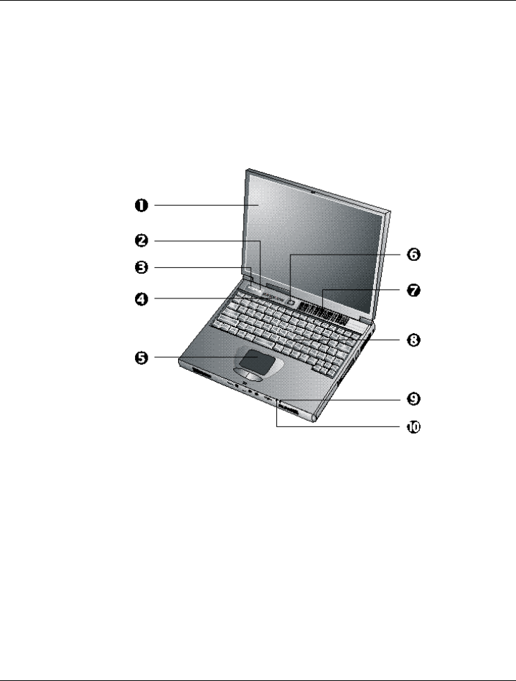
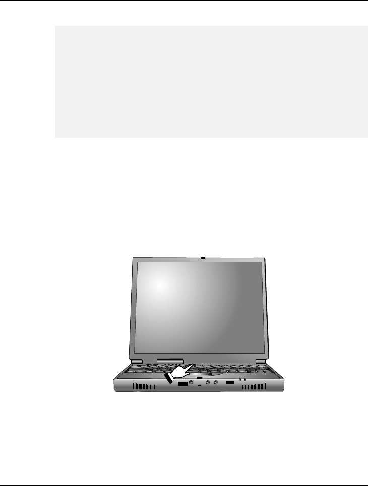
1.3 The Inside of the Notebook
The notebook computer is compact with features on every side. First, look at
the inside of the system. The following sections describe inside features.
¶. Color LCD Display ·. Internet Button
¸. E-Mail Button ¹. Status LED Indicator Panel
º. Touchpad Pointing Device ». Power On/Resume Button
¼. Cooling Fan Vent ½. Keyboard
”. Power Indicator •. Battery Charging LED
• Color LCD Display
The notebook computer comes with a color LCD that you can adjust for
a comfortable viewing position. The LCD can be a 12.1” TFT (Thin Film
Transistor)/DSTN (Dual Scan Super-Twisted Nematic) color LVDS with

Notebook User Guide
17
800x600 SVGA (Super Video Graphics Array) resolution panels, or 13.3”
or 14.1” TFT color LVDS with 1024x768 XGA (Extended Graphics
Array) resolution panels. The features of the Color LCD Display are
summarized as follows:
−DSTN/TFT color LVDS with 800x600 SVGA or 1024x768 XGA
resolution panels.
−Capable of displaying 64K colors (32-bit high color) on either
SVGA or XGA LVDS panels.
−LVDS display control hot-keys allows you to adjust the contrast
of the LCD.
−Simultaneous display capability for LCD and external desktop
computer monitor.
−LCD display can be upgraded from 12.1” TFT to 13.3” or 14.1”
TFT.
• Internet button
This latest technology is designed specifically for providing a very
convenient way in connecting Internet only by pressing Internet button as
shown in the graphics. For more understanding and interesting, you can
refer Section 2.5 to recognize the driver installation procedures in
activating Internet button.
• E-mail button
This is the most convenient way to access the outlook utility just by
pressing this button, you can omit several procedures in entering into
Outlook environment.
• Status LED Indicator Panel
keep you informed of your notebook computer’s current operating status.
Descriptions of the status icons appear in the following section.

Notebook User Guide
18
• Touchpad Pointing Device
Microsoft and IBM PS/2 mouse compatible with two select buttons.
Supports tapping selection and dragging function. It works like a standard
computer mouse. Simply move your fingertip over the Glide Pad to
control the position of the cursor. Use the selection buttons below the
Glide Pad to select menu items.
• Power On/Resume Button
Switches the computer power on and off, or resumes whenever it is in
Suspend mode.
• Cooling Fan Vent
Emits the heat out of your computer and keeps it within operating
temperature.
+
Do not block the fan while the notebook is in use.
• Keyboard
−Standard QWERTY-key layout and full-sized 86/87 keys
keyboard with Windows 98 hot-keys, embedded numeric keypad,
12 function keys, inverted “T” cursor arrow keys, and separate
page screen control keys.
−Wide extra space below the keyboard panel for your wrist or palm
to sit-on comfortably during typing.
• Power Indicator
Lets you know that power to the system is turned on. This LED is
positioned so that you can see the power state whether the LVDS panel is
opened or closed.
ß Lights green when the system is powered on using the AC adapter
or battery.
ß Lights amber when battery is warning in low battery power.
Notebook User Guide
19
ß Lights green blinking when in Suspend to RAM (or Suspend to Disk
if you already created Save to Disk partition in HDD by using
PHDISK utility in the MS-DOS) mode and critically low battery
power. We strongly recommend that users create Save to Disk
partition as this will prevent your data from loss when power is
critically low.
• Battery Charging LED
Lights to indicate battery charging status.
ß Lights amber to indicate the battery is charging.
ß Lights off to indicate the battery is fully charged or no battery
installed.
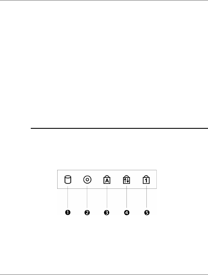
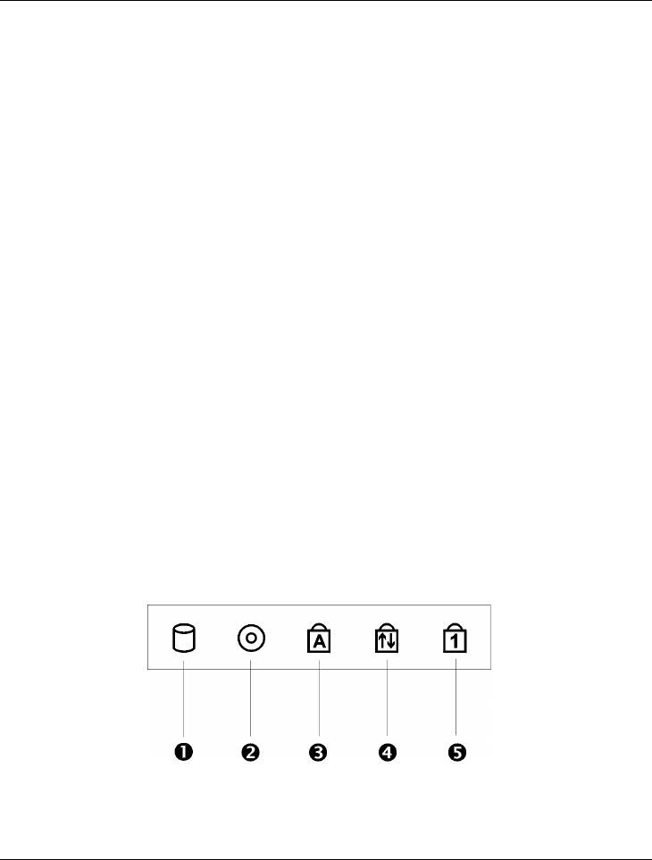
STATUS ICONS
The notebook computer uses status lights marked with icons to communicate
system status. See the following figure and list for each icon’s meaning.
¶. Drive Access ·. Diskette Drive Access
¸. Caps Lock ¹. Scroll Lock
º. Num Lock Status LED Icons

Notebook User Guide
20
• Drive Access
When LED in green light indicates that the system is accessing either the
CD-ROM or DVD-ROM.
• Diskette Drive Access
When LED in green light indicates that the system is accessing data from
or is retrieving data to the floppy diskette drive.
• Caps Lock
When LED in green light indicates that the Caps Lock key on the
keyboard is activated. When activated, all alphabet keys typed in will be in
upper-case or capital letters.
• Scroll Lock
When LED in green light indicates that the Scroll Lock key on the
keyboard is activated. The Scroll Lock key has different functions
depending on the software you are using.
• Num Lock
When LED in green light indicates that the Num Lock key on the
keyboard is activated. When activated, the embedded numeric keypad will
be enabled.
Notebook User Guide
21
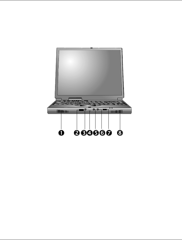
1.4 The Front Side of the Notebook
¶. Built-in Stereo Speakers ·. Optional IR Port ¸. Microphone Jack
¹. Integrated Microphone º. Stereo Line-In Jack ». Headphone Jack
¼. Volume Control ½. Built-in Stereo Speakers
• Built-in Stereo Speakers
Integrated left and right mini stereo speakers for sound and audio output
for your multimedia presentations or listening pleasure.
• Optional IR Port
Wireless data transfer of files between your notebook computer and an
IR-equipped device or notebook computer. You can also print to an IR-

Notebook User Guide
22
equipped printer without using cables. The SIR mode provides up to
115.2Kbps of data transfer rate. This optional port is available for some
models only.
• Audio Ports
From left to right, the jacks are Microphone, Line In & Headphones
described as follows:
ß Microphone Jack
Allows you to connect an external microphone for monophonic
recording or amplification through the unit. Plugging in an external
microphone disables the built-in microphone. Lets you connect an
external microphone to record monophonic sound directly into your
notebook computer.
ß Integrated Microphone
Integrated mono microphone for instant voice recording and
simultaneous voice conversation.
ß Stereo Line-In Jack
Lets you connect an external audio device such as CD player, a tape
deck, or a synthesizer as an input source. Use a cable to connect to
the Line-Out port on the other audio system to record or play.
ß Headphone Jack
Lets you plug in a stereo headphone, powered speakers, or earphone
set with 1/8 inch phono plug for personal listening.
• Thumb Wheel Volume Control
Allows you to control the speaker volume.
Notebook User Guide
23
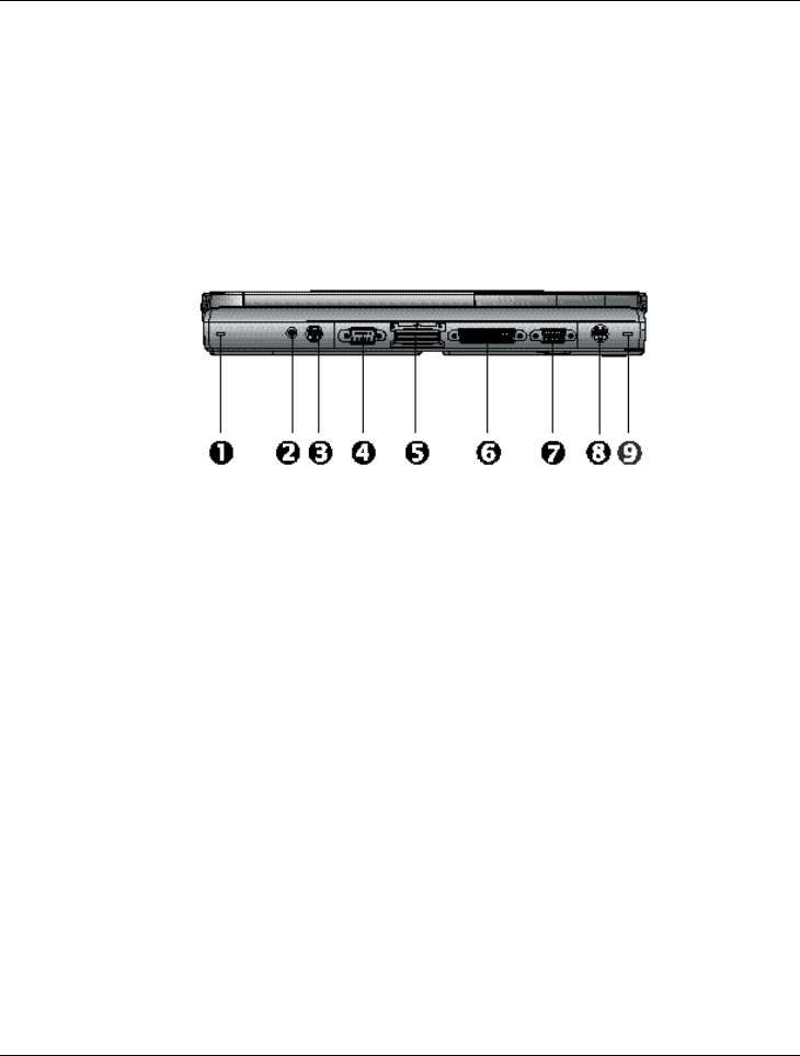
1.5 The Rear Side of the Notebook
You’ll find system ports for connecting optional devices (like a printer or
external monitor) to the back of your notebook computer. The ports are
described after the figure.
¶”. PortBar Notches ·. AC Power Port ¸. PS/2 Port
¹. Serial Port º. Optional Expansion Port ». Parallel Port
¼. Monitor (Video) Port ½. Optional TV Port
• PortBar Notches
Use these notches to secure the PortBar to the back of the system. There
are two PortBar notches located at the both ends of the rear side of the
system.
• AC Power Port
Lets you connect the AC power adapter in supplying continuous power
to your notebook and recharging the battery.
• PS/2 Port
Lets you connect an external PS/2-style mouse, PS/2-style keyboard, or
PS/2-style numeric keypad to the system. With an optional Y-cable

Notebook User Guide
24
adapter, you also can connect any combination on two of these devices
simultaneously.
• Serial Port
Lets you connect a 9-pin external pointing device such as a high-speed
modem, mouse, or other serial devices.
• Optional 80-Pin Expansion Port
Lets you connect to the notebook PortBar. This optional port is available
for some models only.
• Parallel Port
Use this port to connect a parallel printer or other parallel device. The
parallel port supports Enhanced Capabilities Port (ECP) standard. The
standard provides you with a greater processing speed than the
conventional parallel port. The port also supports bi-directional and uni-
directional protocols.
+
The default setting for the parallel port on your notebook computer is set
to Enhanced Capabilities Port (ECP). Some older parallel devices may not
function with the ECP default setting. You may need to adjust the setting
to accommodate your parallel device by changing the BIOS setting.
• Monitor (Video) Port
Lets you attach an external CRT monitor for wider display. You can run
the LCD display and the external CRT monitor simultaneously or switch
it to CRT only using the display hot-key.
• TV Port
Lets you connect to a S-Video TV connector for presentation or VCD,
DVD watching. This optional port is available for some models only.
Notebook User Guide
25
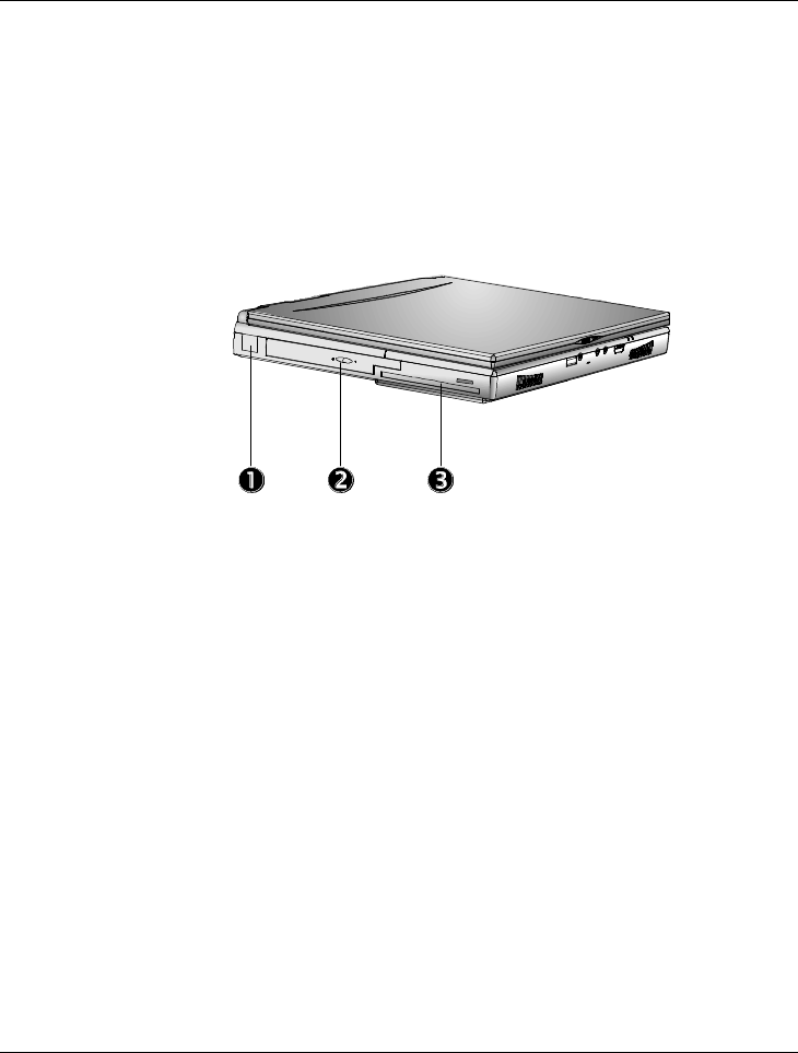
1.6 The Left Side of the Notebook
The left side of your notebook computer provides the features shown in the
following figure.
¶. USB ·. CD-ROM/DVD-ROM
¸. Diskette Drive
Left Side Features
• USB Port
The Universal Serial Bus (USB) port allows you to connect up to 127
USB-equipped peripheral devices (for example, printers, monitors,
scanners and so on) to your notebook computer.
• CD-ROM/DVD-ROM
Allows you to load and start programs from a compact disc (CD) or a
digital video disc (DVD) and play conventional audio CDs.
• Diskette Drive
A 3.5-inch floppy diskette drive comes installed in the notebook
computer. The drive accepts 1.44 MB/1.2MB floppy diskettes.
Notebook User Guide
26
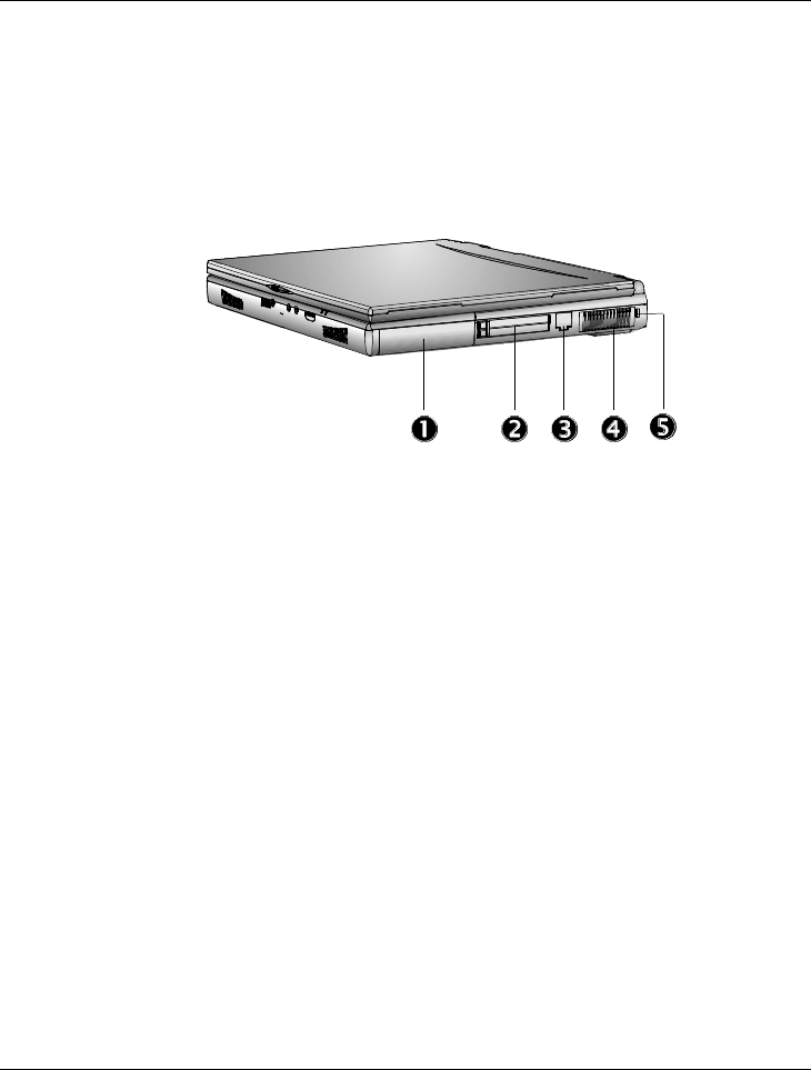
1.7 The Right Side of the Notebook
The right side of the notebook computer offers the features shown in the
following figure.
¶. Battery Bay ·. PC Card Slots
¸. Modem / LAN Port ¹. Cooling Fan Vent
º. Kensington Lock
Right Side Features
• Battery Bay
Stores the Nickel Metal-Hydride (NiMH) or Lithium-Ion (Li-Ion) battery
pack for off-the-cord operation or battery recharging.
• PCMCIA Slot
−Lets you connect various PC cards such as Modem cards, Ethernet
LAN cards, and SCSI cards.
−Double-deck PCMCIA slots that support two Type II PC cards at
the same time, or one Type III PC card in the bottom slot.
−Supports both 5V and 3V 32-bit CardBus and 16-bit PC cards
including PC cards with ZV function. The Zoom Video (ZV) port
is supported in the top slot only.

Notebook User Guide
27
• Modem/LAN Port
If you purchase an internal fax modem, a 56K internal fax/data modem is
installed. It keeps you connected to the outside world through networks.
If you purchase an internal 10Base-T/100Base-TX LAN module, it
connects your computer to other computers/networks through a local
area network (LAN).
Build-in Modem and LAN modules are available as option. You can
install only one module in the notebook PC and cannot use them
simultaneously. If you need to use them simultaneously, you need to use
other PC card in PCMCIA socket instead.
• Cooling Fan Vent
Emits the heat out of your computer and keeps it within operating
temperature.
+
Do not block the fan while the notebook is in use.
• Locking Device Keyhole
Lets you attach a Kensington security system or a compatible lock to
secure your notebook computer.
Notebook User Guide
28
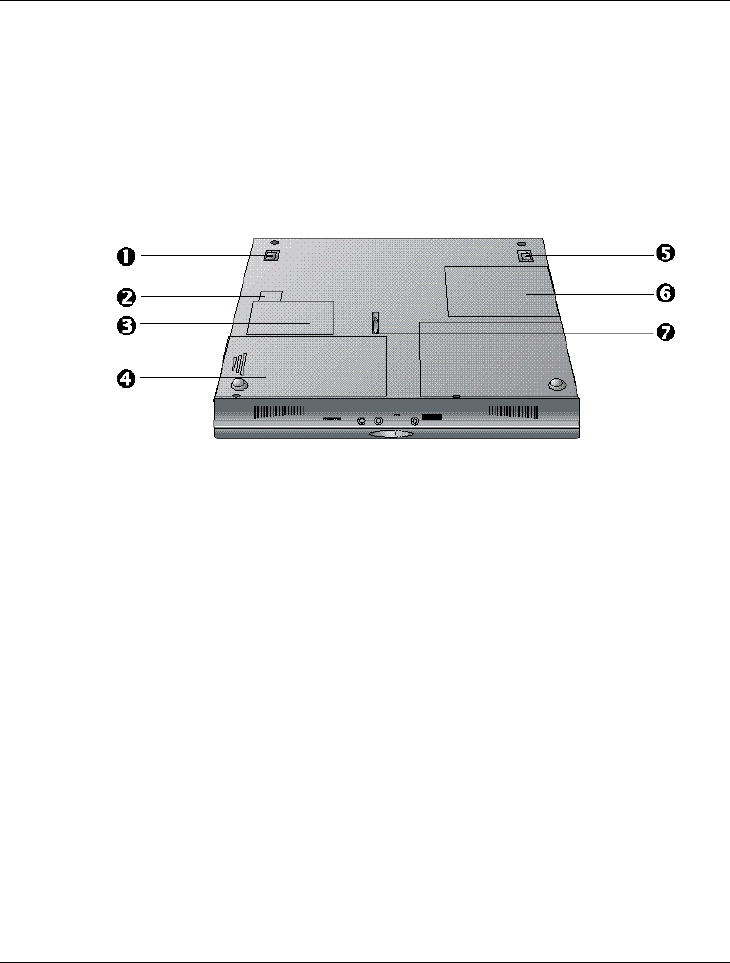
1.8 The Underside of the Notebook
The bottom of the notebook computer offers the following features.
¶. Tilt Foot ·. Modem or LAN Compartment
¸. Modem or LAN Card Compartment ¹. Battery Bay
º. Tilt Foot ». Memory Compartment .
’ Battery Release Latch
Bottom of the System
• Tilt Foot
Provides flexible keyboard angle.
• Modem or LAN compartment
Provides Modem or LAN module inserted into the space.
• Modem or LAN Card Compartment
Provides optional Modem card or LAN card inserted into this compartment for
executing relative functions.

Notebook User Guide
29
• Battery Bay
Equipped with a rechargeable Nickel-Metal-Hydride (NiMH) or Lithium-
Ion (Li-Ion) battery.
• Memory Compartment
Remove the screw to find two DIMM slots. One is inserted with SDRAM
memory board configured by the factory. The other is empty for upgrade
use.
• Battery Release Latch
Slide the latch to the other end and hold it. While holding the latch, slide
the battery bay outwards to remove the battery.
1.9 Notebook Accessories
AC Adapter
The AC Adapter supplies external power to your notebook computer and
charges the internal battery pack simultaneously. The AC adapter has an auto-
switching design that can connect to any 100VAC ~ 240VAC power outlets.
You just change the power cord if you are going to use your notebook in
other countries with different connector outlets.
When you connect the AC adapter, it charges the battery whether or not the
notebook computer is powered on.
Battery Pack
Aside from the AC adapter, your computer can also be powered through the
internal battery pack. The battery pack uses rechargeable Nickel-Metal
Hydride (NiMH) or Lithium-Ion (Li-Ion) battery cells that provide long
computing hours when fully charged and power management enabled. You

Notebook User Guide
30
should always leave the battery inside your computer even when using the AC
adapter as it also acts as a back-up power supply in case power from the AC
adapter is cut off. It is also very important to have the battery pack always
charged to prevent battery cell degradation.
1.10 Notebook Options
DVD-ROM Device Pack
This device pack option plugs into the Device Bay and used for reading DVD
or playing DVD titles. DVD-ROM drives are also backward compatible with
CD-ROM, so you can also use any audio CDs, video CDs, photo CDs, and
recorded CD (CD-R).
Internal Ethernet LAN module
This notebook comes with an optional 10Base-T/100Base-TX LAN module
that supports data transfer rates at 10Mbps and can be up to 100Mbps.
Internal Modem Module
This notebook comes equipped with a 56K capable internal fax/ data modem
that allows you to communicate with others via fax, email, or connect to an
online service or bulletin board.

Notebook User Guide
31
Notebook User Guide
32
2Getting Started
Your Notebook is designed and pre-configured for
easy setup and use. This chapter describes the
installation steps you should follow to get the
notebook up and running as quickly as possible.
Contact your dealer if they have pre-installed all the
needed drivers to fully operate your computer or if
there is an update on the driver installation of the
notebook.

Notebook User Guide
33
2.1 Using the Battery Pack
The notebook is designed to operate with one of the following power sources:
• With AC power using the AC adapter connected to an electrical outlet.
• With a Nichel Metal-Hydride (NiMH) or Lithium-Ion (Li-Ion) battery
pack.
You should use the AC adapter whenever possible, relying on the battery pack
only when AC power is unavailable.
Before you use your notebook computer, install and recharge the battery pack
first. The rechargeable Ni-MH or Li-Ion battery pack allows you to operate
the notebook without an external power source. When you connect the AC
power adapter, the battery immediately starts to recharge. Normal battery
charging time is 2.5 ~ 3.5 hours for Lithium-Ion (Li-Ion) battery pack when
your computer is turned off.
For maximum battery performance, fully discharge the battery first before
recharging it. To do so, unplug the AC adapter, turn off power management
features (through Setup and Windows), and turn on the system. Once the
battery is fully discharged, plug in the AC adapter and recharge the battery.
If you do not discharge the battery completely, it fails to accept a full
recharge.
+
For Li-Ion battery, it is not necessary to discharge the battery before
recharge it. Li-Ion battery is vulnerable than Ni-MH battery, do not
charge it with other power adapter, or it may cause fire or explosion.
Notebook User Guide
34
Installing the Battery Pack
This notebook provides the most convenient way to install the battery pack
into your computer. With the extended nose directed toward the
compartment, insert the battery pack.
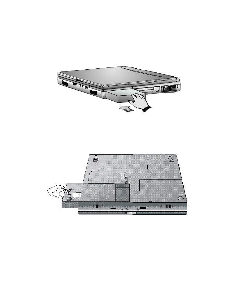
Removing the Battery Pack
To remove the battery pack, slide the latch and push out the battery pack
simultaneously.
Replacing the Battery Pack
When your notebook estimates that the battery only has enough charge to
continue for a few minutes, it will alert you to a low battery condition by
blinking the battery icon on the LED status panel and a battery low warning
beep. If you are consuming a lot of power by using the audio system, the

Notebook User Guide
35
PCMCIA slots, the hard, floppy disk drives, and CD-ROM drive (or DVD
ROM drive), your notebook might run out of charge much sooner than you
expect. You should always respond to the battery low indication by connecting
to AC power or turning off your notebook, or suspending your notebook to
disk. If you do not do so, the notebook will automatically suspend to disk and
turn off. The contents of the memory will store in the Suspend-to-Disk
partition. You will be unable to restart the notebook until you have connected
to the AC adapter or installed a charged battery. To replace the battery pack,
refer to the previous sections on “Installing the Battery Pack” and “Removing
the Battery Pack.”
+
If you do not have a “Suspend-to-Disk” partition or file prepared
beforehand and the battery is running low, the system will not be able to
enter suspend to disk mode, but would rather enter suspend to RAM
mode. The contents will be saved to the memory instead and you need to
connect the AC adapter.
+
Be sure to save your data before replacing the battery pack or connecting
the AC adapter. Failure to do so can result in data loss.
EXTENDING BATTERY LIFE
It is important to be aware of the simple things for extending the life of the
system main battery while you are on the road. You should find a working
place where the external lighting is not too bright and turn down the screen
brightness and contrast. Also, please refer to Chapter 6 “Customizing Your
Computer” for details about power management features and the modes
available.
Notebook User Guide
36
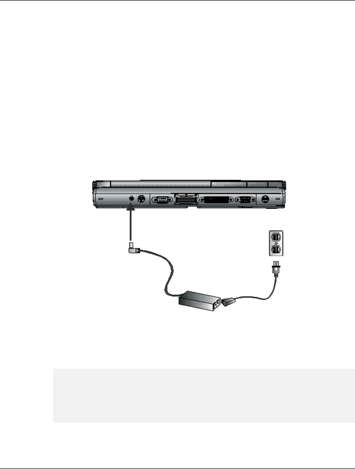
2.2 Connecting the AC Power Source
The AC adapter provides external power source to your computer and charges
the internal battery pack at the same time. The AC adapter also has an auto-
switching design that can connect to any 100VAC ~ 240VAC power outlets.
To connect the power adapter:
1. Plug the AC power cord into the power socket of the AC power adapter.
2. Plug the other end of the AC power cord to a live AC wall outlet.
3. Plug the connector of the AC adapter to the DC-IN port found at the
back of the computer.
+
Whenever possible, it is advisable to always have the AC adapter
connected to the notebook and the battery pack installed. This ensures
continuous power supply and prevents any data loss incurring from
sudden power breakdown.
Notebook User Guide
37
+
Ÿ
For the power supply of this equipment, an approved power cord has to
be used. For a rated current up to 6A and an equipment weight more
than 3kg, a power cord not lighter than H05VV-F, 2G, 0.75mm2, has to
be used.
Ÿ
Make sure the socket and any extension cord(s) you use can support
the total current load of all the connected devices.
Ÿ
Before cleaning the computer, make sure it is disconnected from any
external power supplies (i.e. AC adapter or car adapter).
2.3 Starting Your Computer
The Power/Resume button is found on the top of the base unit. Press the
Power/Resume button to start your computer and check that if the Power
LED turns on.
After a few seconds, the computer’s display will turn on and your computer
will begin to execute the Power On Self Test or POST to check if all system

Notebook User Guide
38
components are running properly. Any errors found during the test will be
displayed on the screen and may generate short beep sound as well.
After the test, the screen will also display a message “press <F2> to enter
SETUP”. You don’t need to run this program at the moment as your dealer
already made the necessary settings for your computer optimal operation.
Refer to Chapter 6 on running the SETUP program later.
After the test has completed, your computer will start to search and boot up
the operating system from your hard drive. The notebook computer normally
comes with a Windows 98/2000 operating system pre-installed in your hard
drive. Consult the Windows 98/2000 manual on how to use the program. If
not, contact your dealer for assistance.
2.4 Adjusting the Display Controls
The LCD brightness adjustment is controlled by <Fn> +<F8> and <Fn> +
<F9> keys respectively. You need to press these hot-key controls after
powering on your notebook to suit your viewing pleasure. Press the <Fn>
key using your left finger and while still holding the key, press the arrow
cursor keys using your right finger.
+
For TFT color screens, only the Brightness hot-key controls are
functional.
The Brightness hot-key control adjusts the brightness on the LCD. The
brightness hot-key control will not set the LCD completely dark or bright; it
provides sufficient lighting to the LCD to match the external lighting of the
surrounding. The brighter the room, the more you need to increase the
brightness of the LCD.

Notebook User Guide
39
2.5 Installing the Notebook Device
Drivers
If you already have an operating system like DOS or Windows installed into
your notebook computer, it is best to install the needed device drivers for
using the built-in devices of your computer. Before installing the drivers,
check with your dealer first if they have already installed all the drivers along
with the operating system. If not, follow the procedures below:
RUNNING THE PHDISK SUSPEND UTILITY
The PHDISK utility of the notebook allows you to create a suspend-to-disk
(STD) partition or file that is used to save the opened files when you activate
STD mode and power off the computer. If you want to make use of the STD
feature, you need first to run the PHDISK utility. There are two options for
executing this utility:
1. PHDISK /Create /Partition - you can choose to run Suspend-to-Disk
and save your work into an allocated fixed disk partition. This option
should be done before partitioning and formatting your hard disk. The
advantage of this option is that it is more secure since the files are saved
in a separate partition and has no risk of being deleted. The disadvantage
of this is that you need to allocate enough disk partition for future
memory upgrade. The STD partition should always be larger than the
system memory RAM.
2. PHDISK /Create /File - you can also choose to run Suspend-to-Disk
and save your work into a STD file. You do not need to allocate an extra
disk partition when running this option. The advantage of this is that you
do not need to allocate or waste extra disk partition. The disadvantage of
this option is that it is less secure since there is risk of deleting the STD
file although the file is hidden.

Notebook User Guide
40
RUNNING THE PHDISK /CREATE /PARTITION
Before you run this option, you should carefully consider how much disk size
you need to allocate for the STD partition. The STD partition should be larger
than the installed system memory RAM. If you are planning to install more
memory in the future, it is recommended to allocate more disk space. Run
FDISK under DOS and leave around 5% of disk space for Non-DOS
partition. This will later be used by the PHDISK for creating the STD
partition.
If you already run FDISK before, you need to delete the original partition of
the hard disk.
Load the notebook driver CD and look for the PHDISK program file. Run
“PHDISK /Create /Partition” or “PHDISK /C /P”. The PHDISK utility
program will automatically assign a disk size in reference to the installed
system RAM to be allocated for the STD partition. After PHDISK has
completed the STD partition, you will be prompted to reboot the system.
RUNNING THE PHDISK /CREATE /FILE
Creating a STD file is much simpler since you do not need to allocate an extra
disk partition. Load the notebook driver CD and look for the PHDISK
program file. Run “PHDISK /Create /File” or “PHDISK /C /F”.
PHDISK will create the SAVE2DSK.BIN file on Drive C. The size of this
file will depend on the installed RAM memory of your computer. This file
also is hidden and has read-only attributes. You must not delete this file.
+
During power on or restart, the system will detect if STD partition or file
is present. If not, it will show a red colored dialog box informing you that
“Save to Disk Partition Not Present” and “Save to Disk Feature
Disabled”. This warning message can be disable from "Advanced", "Save
to Disk Warning" in BIOS setting by pressing F2 during system boot

Notebook User Guide
41
+
Whenever you upgrade the memory, you need to delete the existing STD
partition or file and create a new one according to the new memory size.
Run PHDISK /Delete /Partition or PHDISK /Delete /File to delete
existing STD partition or file.
Installing Windows NT/2000 from CD-ROM or DVD ROM
To install Windows NT directly from your CD-ROM or DVD-ROM, insert
Windows NT installation CD into CD-ROM drive and enter BIOS Setup
menu. Go to Boot menu and select “ATAPI CD-ROM Drive” as your boot
device. For NT user, Please go to Advanced menu, then Installed OS, then
select “Others” and select “ATAPI CD-ROM Drive” as your boot device.
Go to Exit menu and select “Exit Saving Changes”.
Installing Windows 98/95/Me from CD-ROM or DVD-
ROM
The easiest way to install Windows 98/95 is to boot from Windows 98 start-
up disk. With Windows 98 start-up disk, you don't need to install CD-ROM
driver since the start-up disk can support virtually all CD-ROM device. Insert
Windows 98 Installation CD into CD-ROM drive and run “setup.exe”.
INSTALLING THE VGA DEVICE DRIVER
Following is the procedure for installing the Trident Video Accelerator 3D
Adapter (English) VGA driver to your computer:
Installing VGA driver for Windows 2000
1. Boot Windows 2000 from your hard disk and insert the disc containing
the VGA driver for Windows.

Notebook User Guide
42
2. Click the Start button, then click Settings, and Control Panel. Double
click System and then "Hardware", click Device Manager tab.
3. Click Display adapters and double click Trident Video Accelerator
CyberBlade-il Select the Driver page and click Update Driver button.
4. Click Next to continue.
5. Tick Specify a location and Have Disk, then click Browse button.
Then, navigate to “E:\Driver\Win2k\VGA” and click Next.
6. Click Next to accept the updated VGA driver
7. Click Finish and then restart computer to finish VGA driver installation.
Installing VGA device driver for Windows NT/98/Me
1. Insert the CD containing the VGA driver for Windows into CD-ROM
drive.
2. Click the Start button, then point to Settings, and click Control Panel.
3. Double-click on the Display icon and click on the Setting tab.
4. Click Advanced then Adapter
5. Click Change and Next, then select Display a list of all the drivers in
a specific location. Now you can select the driver you want, then click
Next.
6. Click Have Disk to change display driver from CD-ROM
7. Click Browse button and navigate to the VGA driver location as
“E:\Driver\NT4.0\VGA” “E:\Driver\Win98\VGA”.
8. Click the OK button and select Next to continue the setup procedure.
9. Select Yes to restart your computer in order to finish the setup
procedure.

Notebook User Guide
43
INSTALLING THE MODEM DEVICE DRIVER
Following is the procedure for installing the ASKEY Data Fax Modem driver
to your computer:
Installing modem driver for Windows 2000
1. Click the Start button, point to Settings, then click Control Panel.
2. Double-click on the System icon, Hardware, then click on the Device
Manager folder tab.
3. Under the Other Devices line, highlight the PCI Simple
Communications Controller.
4. Double Click PCI Simple Communications Controller, then click
Driver
5. Select Update Driver, then Next
6. Select “Search for a suitable driver for my device”, and click Next.
7. Tick on “Specify a location box”. Then, click Next and Browse button
and navigate to the modem driver location as
“E:\Driver\Win2K\Modem”. Click OK and Next to begin searching
the driver.
8. Click Next then Finish to complete the modem driver installation.
Installing modem driver for Windows NT
1. Boot Windows NT from your hard disk and insert the disc containing the
Modem driver for Windows.

Notebook User Guide
44
2. Click the Start button, then click Run. In the Run dialog box, click
Browse button and navigate to the directory as
“E:\driver\NT4.0\modem\setup.exe” where the modem driver is
located.
3. Click OK to run the program. The EDSP Configuration box appears for
you to set up the COM port.
4. Click OK. Then, point to Start, Settings, and Control Panel.
5. In the Control Panel box, double click the Modem icon. The Install New
Modem message box appears. Click Next to detect modem.
6. When your modem are detected, a message box will appear to advise you
the detected modem with its COM port. Click Next to continue with the
installation.
7. Click Finish to show the Modem Properties message box. You will see
the modem type and the attached port here.
8. Click Close to end this driver setting.
Installing modem driver for Win98/WinMe
1. Run E:\Driver\Win98\Modem\Setup.exe
2. Click Next to process next procedure.
3. It will prompt you to insert CD or disk. Click OK then click Browse, and
navigate to the modem driver location as "E:\Driver\Win98\Modem and
then click OK
4. Select "Yes, I want to restart my computer now" to finish the
installation

Notebook User Guide
45
INSTALLING THE LAN DRIVER
Following is the procedure for installing the Intel 82559 Fast Ethernet LAN
driver:
Installing LAN driver for Windows NT
1. Boot Windows NT from your hard disk and copy the whole
“E:\Driver\NT4.0” folder into the hard disk. (Install from CD
directly is not commended).
2. Click the Start button, then click Settings, and Control Panel. Double
click Network and click Yes to install network.
3. With Wired to Network box ticked on, click Next.
4. Click Select from list and Have disk.
5. Type "E:\Driver\NT4.0\LAN" and click OK.
6. Click OK and click Next to proceed with next step.
7. Select Network Protocols you need and click Next to proceed the next
step.
8. Select Network Services and click Next to proceed the next step.
9. Click Next to continue installation.
10. When Windows prompts you that Setup needs to copy some Windows
files, insert Windows NT disc and type "E:\i386". Then, click
Continue.
11. Select "Intel PRO PCI Adapter" and click Continue.
12. Windows will ask you if you have DHCP server on your network. Ask
your system administrator and click either Yes or No.

Notebook User Guide
46
13. After enabling or disabling network binding, click Next to continue with
the next procedure.
14. Click Next to start network.
15. Windows might ask your computer name, workgroup or domain. Input
your data and click Next.
16. Finally, click Finish and click Yes to restart computer.
Installing LAN driver for Windows Me/2000
1. Install the LAN module first and boot Windows from your hard disk and
insert the disc containing the LAN driver for Windows.
2. Click the Start button, then click Settings, and Control Panel. Double
click System (for Win 2000, you need to click one more tab "Hardware")
and click Device Manager.
3. Highlight "Intel 8255X-based PCI Ethernet Adapter (10/100)" or
“Network Adapter” and then click Update Driver
4. Select "Specify the location of the driver" or “Specify a location” and
click Browse to E:\Driver\WinMe\LAN (Please change to “Win2K”
as the OS you are using) please specify 82557.inf file and click Next
5. Select "One of the other package"(WinMe), then select "Intel 8255X-
based PCI Ethernet Adapter (10/100)
6. Follows the instruction of the system to finish and restart the computer.
Installing LAN driver for Windows 98
1. Boot Windows 98 from your hard disk and insert the disc containing the
LAN driver for Windows 98.

Notebook User Guide
47
2. Click the Start button, then click Settings, and Control Panel. Double
click System and click Device Manager tab. Under Other devices,
you'll see PCI Ethernet Controller. Select it and click Remove button.
3. Click Refresh button. The Add New Hardware Wizard will detect PCI
Ethernet Controller. Click Next to search for the driver.
4. Click Next to continue.
5. Tick Specify a location and click Browse button. Then, navigate to
“E:\Driver\Win98\LAN” and click Next.
6. Click Next to accept the updated driver for Intel 8255X-base PCI
Ethernet Adapter (10/100).
7. Click Next to continue with LAN driver installation.
8. Insert the disk labeled “Windows 98 Second Edition CD-ROM”, and
then click OK.
9. Type “E:\Win98”, then click “OK”.
10. Click Finish to complete installation.
11. Restart Computer to finish setting up LAN.
INSTALLING THE AUDIO DEVICE DRIVER
Your notebook computer uses the VIA PCI Audio controller embedded in
VIA chipset core.
Installing Audio Driver for Windows NT4.0/98/2000/Me
1. Boot Windows from your hard disk and insert the disc containing the
Audio driver for respective Windows version.

Notebook User Guide
48
2. Click the Start button, then click Run. In the Run dialog box, click the
Browse button and navigate to the directory as “E:\driver\
Win98\Audio” “E:\driver\NT4.0\Audio”,
“E:\driver\Win2k\Audio” and run “setup.exe”.
3. Click Next to proceed with the next step.
4. Select Install and click Next to begin installing the audio driver.
5. For NT user, it is necessary to Add VIA Audio Controller and VIA
MIDI External Port. Then you can also select whether install
Microsoft Sidewinder 3D Pro Joystick or not.
6. Select “Yes, I want to restart my computer now” and click Finish to
complete the audio installation.
7. For Win98, the Notebook PC will also need Windows 98 operating
system driver to complete the installation.
INSTALLING EASY BUTTON DRIVER
Following is the procedure for installing the Internet and e-mail button keys.
Installing Easy Button driver for Windows NT/98
1. Boot Windows from your hard disk and insert the disc containing the
Internet/e-mail button driver.
2. Click the Start button, then click Run. In the Run dialog box, click
Browse button and navigate to the directory as
"E:\driver\Win98\Easy button\setup.exe". Please use “NT4.0”
path for Windows NT
3. The Welcome dialog will appear. Click Next to continue with the
installation.

Notebook User Guide
49
4. If you wish to install the driver in a different directory, click Browse.
Otherwise, click Next to continue with the next step.
5. The Select Program Folder dialog box will appear. To setup icon on a
different folder, you may type a new folder name or select one from the
existing Folder list. Click Next to continue.
6. Click Finish to complete installation.
INSTALLING ZV-PORT DRIVER
The upper pcmcia slot of your notebook supports ZV-port. You need to ZV-
port driver before you can use the slot for mpeg card. Following is the
procedure for installing the ZV-port driver.
Installing ZV-port driver for Windows 98/WinMe
1. Boot Windows from your hard disk and insert the disc containing the
ZV-port driver.
2. Click the Start button, then click Run. In the Run dialog box, click
Browse button and navigate to the directory as "E:\Win98\driver\ZV-
port\setup.exe". Please use “WinMe” path for Windows Me
3. Click Next to continue.
4. The Welcome dialog box will appear. Click Next to continue with the
installation.
5. The User Information dialog box will appear. After inputting the name
and company, click Next to continue.
6. Click Next to start copying files.
7. Click Finish to complete Setup.

Notebook User Guide
50
Installing ALPS – Touch Pad driver for Windows
98/Me/2000
1. Click the Start button, then point to Settings, and click Control Panel.
2. Double-click on the System icon (For Win2000, please one more tab
“Hardware”), and then click on the Device Manager folder tab.
3. It will find the mouse, and then double click PS/2 Compatible Mouse
Port
4. Click Driver, and then Update Driver
5. Click Next and select Display a list of all the driver in a specific
location for you to select the driver you want.
6. Click "Have Disk" then click Browse to navigate to
"E:\driver\Win98\Touch Pad and then OK to search driver
7. We are applying the certificate of driver to Microsoft currently. You can
bypass the license declaration and continue to install the driver. Follow
the instruction to finish the installation. If the mouse fails to response, it is
normal, because the driver is changed. Please just press the Enter and
restart the computer by keyboard to finish the installation.
2.6 Turning off Your Computer
If you are not going to use the computer for awhile, it is best to turn off the
power of the computer for longer use. Before turning off the power, you need
to close first all application programs and shutdown the operating system.
Then, press the power button to switch off the power of your computer. If
you are using Windows 95/98 or its newer version, the system will power off
by itself whenever you shut down the operating system.

Notebook User Guide
51
After turning off the computer, make it a habit to leave the LVDS panel open
for a while whenever used for an extended period of time. This allows the
inside parts of the computer to cool off. Closing the panel will force the heat
up against the LCD screen, which may degrade the LCD when done regularly.
More importantly, never close the LVDS panel for a long period of time when
computer is on and power saving features are disabled.
Notebook User Guide
52
3Using Your Notebook
This chapter describes how to operate the standard
built-in features of the notebook that you normally would
use in your day-to-day computer work. If you are new to
computers and to your operating system, you also need to
read the manual for the operating system on how to work
with your computer. It is very important to familiarize
yourself well with the operating system. The succeeding
chapters let you know how to go beyond the basics and
try other exciting features.
Notebook User Guide
53
3.1 Starting Your Operating System
The operating system is a must ingredient in using your computer. Without an
operating system, it is like playing chess without the chessboard. It is the
platform for all your software application programs to run on. The most
popular operating system today is Microsoft Windows. You should have one
installed by your dealer unless you are an expert computer user and would
need a more powerful operating system. If you have an operating system
already installed in your computer, then you would be up and running after
you power on your computer and boot up the system. Check your operating
system manual on how to run it.
3.2 Knowing the Status of Your Computer
The Status LED Panel, located at the top of the base unit, provides you with
several graphical icons with LEDs (Light Emitting Diode) in representing
your system’s activity and status. This includes power source and power
management status. You will glance it from time to time as you use your
computer.
¶. Drive Access ·. Diskette Drive Access

Notebook User Guide
54
¸. Caps Lock ¹. Scroll Lock
º. Num Lock Status LED Icons
• Drive Access
The drive folder icon indicates that the system is accessing either the
HDD, CD-ROM, or DVD-ROM.
• Diskette Drive Access
The drive folder icon indicates that the system is accessing FDD. When
this LED lights, the notebook writes data to or retrieves data from the
floppy diskette drive.
• Caps Lock
The Caps Lock icon indicates that the Caps Lock key on the keyboard is
activated. When activated, all alphabet keys typed in will be in upper-case
or capital letters.
• Scroll Lock
The Scroll Lock icon indicates that the Scroll Lock key on the keyboard is
activated. The Scroll Lock key has different functions depending on the
software you are using.
• Num Lock
The Num Lock icon indicates that the Num Lock key on the keyboard is
activated. When activated, the embedded numeric keypad LED will be
enabled.
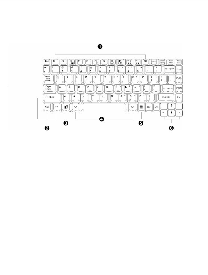
3.3 Understanding the Keyboard
Functions
Your notebook computer is equipped with an 86-key keyboard that provides
all the functionality of a full-sized 101 or 102-key IBM keyboard. Aside from
Notebook User Guide
55
the standard typewriter-layout keyboard of your computer, there are a number
of extra features and function controls on the built-in keyboard including
Windows 95/98 hot keys.
¶. Function Keys ·. Control Keys
¸. Windows Start Menu Key ¹. Control Keys
º. Windows Shortcut Key ». Cursor Control Keys
Keyboard
Key features and operations are described below:
• Function Keys
Function keys are application-driven, like F1 through F12 can be found
on the keyboard. These keys work together with the Fn key to activate
special functions. Some keys (printed in blue on keypad) are
preprogrammed with dual functions.
• Windows 95/98 keys
Use the following two keys to facilitate your work:

Notebook User Guide
56
ß Start Menu key
Displays the Start menu.
ß Shortcut/Application key
Provides quick access to shortcut menus. This key acts like a right
mouse button.
• Cursor Control keys
Cursor control keys let you position the cursor on the screen where you
want. In the screen, the cursor is a blinking underline, block, or vertical
bar depending on the application. The cursor indicates where the next
text typed is inserted.
• Typewriter keys
Typewriter keys (also called alphanumeric keys) are used to enter text and
characters. Keys with blue print on them behave differently when
combined with control keys.
• Control keys — Ctrl, Alt, Fn, and Shift are controls used in conjunction
with other keys to change their functions. To use control keys, press and
hold the control key while pressing another key. For example, “Press Ctrl
C” means to hold down the Ctrl key and type the letter C. Key
combinations work specific to the application you are running.
Notebook User Guide
57
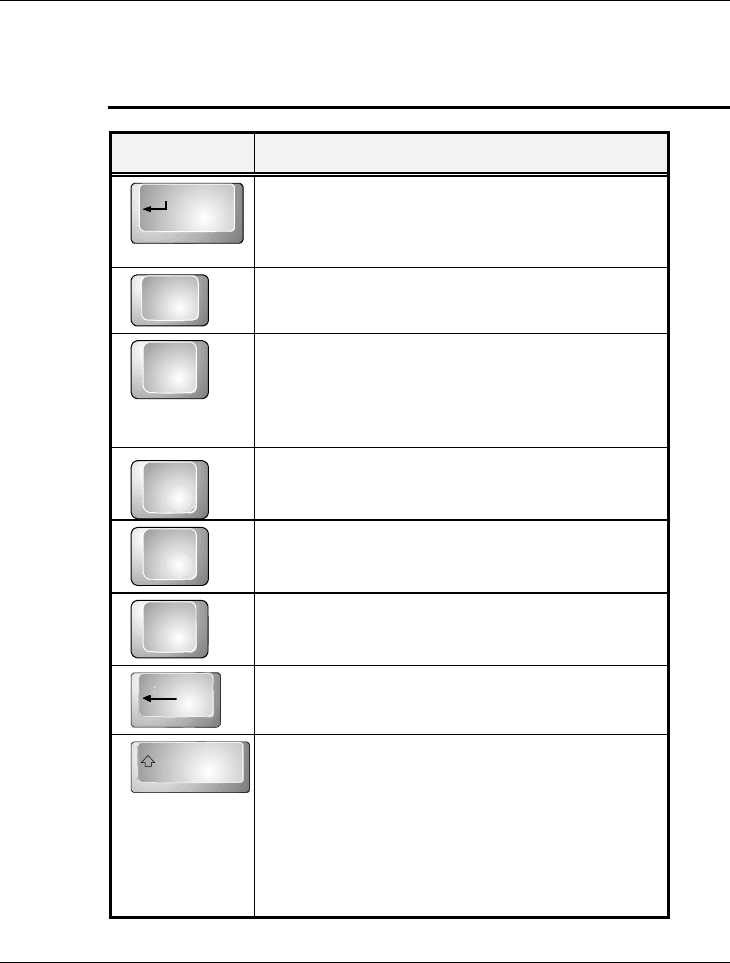
BASIC KEYBOARD FUNCTIONS
Keypad Function Description
Enter
<Enter> key. Execute a command. Within many
text editing application programs, the <Enter>
key inserts a hard carriage return, just like what
ordinary typewriter does.
Esc<Esc> key. Press this key to cancel or escape
from a command or function.
SysRq
Prt Sc
<PrtSc> key. Known as the Print Screen key.
Press this key to send information on the screen
to a printer connected to the parallel port.
<SysRq> key. Used for multitasking operating
system.
Break
Pause
<Pause Break> key. Press this key to temporarily
halt execution of a command. Pressing any other
key resumes execution of a command.
Ins<Ins> key. Known as the Insert key. Press this
key to toggle the keyboard data entry from insert
to type over mode.
Del
<Del> key. Known as the Delete key. Press this
key to delete the character to the right of the
cursor, or delete marked texts or items.
Backspace<Backspace> key. Press this key to delete the
character to the left of the cursor.
Shift
<Shift> key. Press this key in combination with
alphabet letters to produce uppercase letters in
typing. Use this key in combination with those
two-character keys (found on the second row of
the keyboard) to produce the upper marked keys.
Also used in most application program in
combination with other keys to execute a certain
command.
Notebook User Guide
58
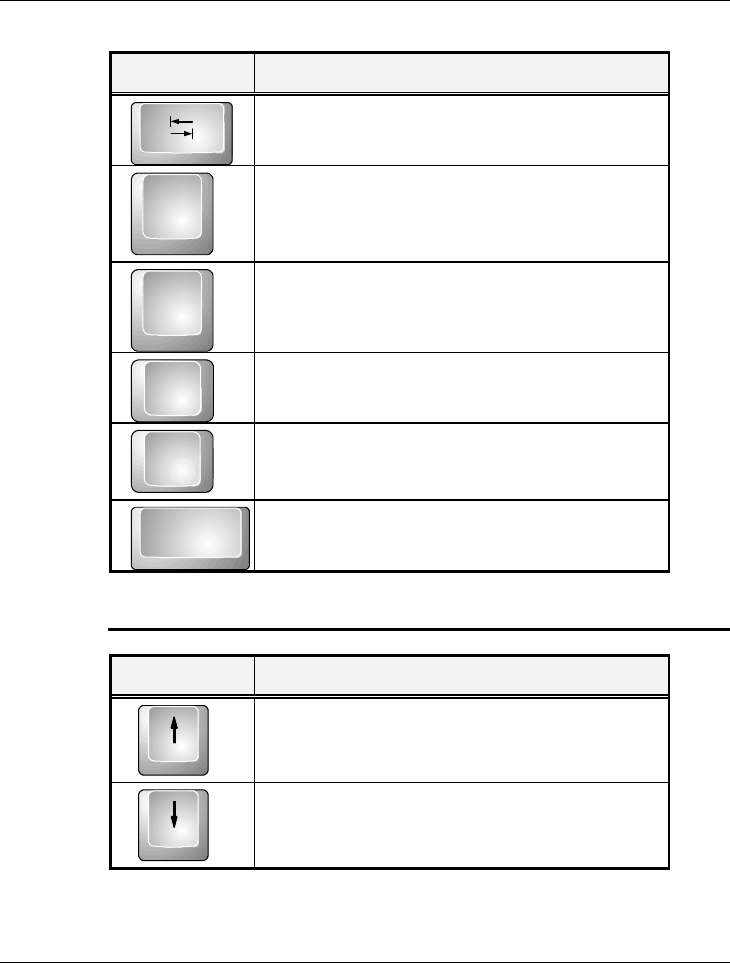
Keypad Function Description
Tab
<Tab> key. Press this key to move the cursor to
the next tab stop on the right. This key works
much the same as in ordinary typewriter.
Ctrl
<Ctrl> key. Known as the Control key. Used in
most application program in combination with
other keys to execute a certain command.
Alt
<Alt> key. Known as the Alternate key. Used in
most application program in combination with
other keys to execute a certain command.
ScrLocK
<Scroll Lock> key. Used in most application
program to scroll the screen without having to
move the cursor.
Num
LocK
<Num Lock> key. Activates the embedded 15-
key numeric keypad. The keys are color coded
blue.
Caps
Lock
<Caps Lock> key. Used in most application
program to always activate uppercase alphabet
characters.
CURSOR CONTROL KEYS
Keypad Function Description
Up arrow key. Moves the cursor up one line at a
time.
Down arrow key. Moves the cursor down one
line at a time.
Notebook User Guide
59
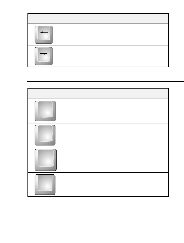
Keypad Function Description
Left arrow key. Moves the cursor to the left one
space at a time.
Right arrow key. Moves the cursor to the right
one space at a time.
SCREEN CONTROL KEYS
Keypad Function Description
Home
<Home> key. Moves the cursor to the beginning
of a screen or line.
PgUp<PgUp> key. Moves the cursor up one screen at
a time
PgDn
<PgDn> key. Moves the cursor down one screen
at a time
End
<End> key. Moves the cursor to the end of a
screen or line.
Notebook User Guide
60
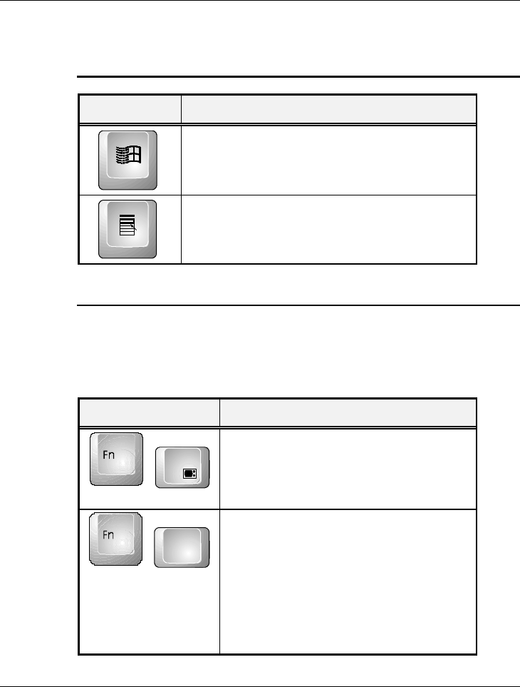
WINDOWS 95/98 HOT KEYS
Keypad Function Description
<Start> key. Pulls up the Windows 95 Start
menu.
<Right Click> key. Performs a mouse right-click
function for Windows 95/98.
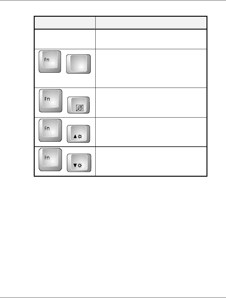
SPECIAL FUNCTION KEYS
The notebook has special system function keys which activate key serving
dual functions. When pressed in conjunction with the <Fn> key, these keys
set specific system parameters and are sometimes referred to as “hot keys”.
Keypad Function Description
+
F3
Switches display between LCD, CRT, or
LCD and CRT simultaneously.
+F4
ß In DOS/Win95/Win98 (APM mode)
/WinNT, means to enter Suspend-to-
RAM mode. Your files will be saved
into the memory and power off the
computer. The Power Saving LED will
also blink. Press the power button to
resume.
Notebook User Guide
61
Keypad Function Description
ß In Win98 (ACPI mode)/Win2000, no
function in this environment.
+
F5
Switch the LCD display mode in expanded
or non-expanded view. These combination
keys only work in a 640x480 resolution
mode.
+
F6
Enable or Disables the built-in system
speaker volume to on or off mode.
+F8
Increases the brightness of LCD display
incrementally.
+F9Decreases the brightness of LCD display
incrementally.
3.4 Using the Glide Pad Pointing Device
Your computer comes with a built-in Glide Pad pointing device that is found
on the center of the palm-rest surface.
The Glide Pad offers a number of options that let you customize how it
functions. To access these options, locate the Control Panel and double click
on the mouse icon. The options let you control the size and color of the
cursor, cursor speed, the accepted double-click speed, and selection button
orientation.
The Glide Pad works a mouse pointing device replacement that is used under
Notebook User Guide
62
Windows-based operating system. Before using the Glide Pad, you need first
to load or install the device driver to activate the device. You can also use the
standard Microsoft or IBM PS/2 driver which is compatible with the Glide
Pad device and is normally used under Windows-based operating system.
However, if you want to utilize the added features of the Glide Pad, you may
want to try installing its own device driver that comes with added utilities for
enhancing the function of the device.
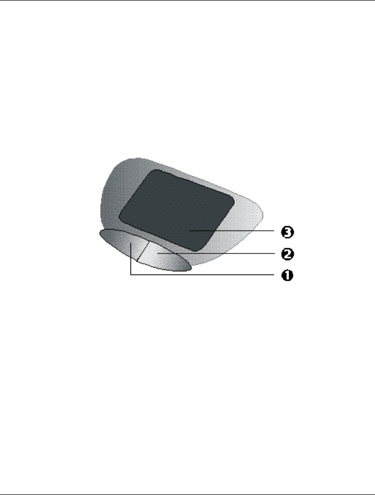
¶. Left Selection Button ·. Right Selection Button
¸. Glide Pad
Glide Pad Features

Notebook User Guide
63
Here how to use the Glide Pad pointing device:
1. The rectangular surface acts like a miniature duplicate of your display
screen. To move the mouse cursor, place the finger lightly on the sensor
pad and move in the desired direction. If you reach the end of the pad,
lift your finger and place it back down on the other side of the pad.
2. To select an item, click on the item by pressing the left button control or
by simply tapping on the surface once. A light, quick tap always works
best. To execute an item, click the left button twice or do a quick double
tap on the surface.
3. To simulate holding the mouse button down (dragging an icon or
selection), use the tap-and-drag gesture. This feels much like a double-
click, except that the finger remains on the pad after the second tap: Tap,
lift, tap, hold and move. The simulated button remains held as long as the
finger remains on the pad.
+
Avoid spilling any liquid on the Glide pad surface and always keep the
Glide pad surface and pointing finger dry from sweat build-up. Also do
not expose Glide pad to any magnetic source object.
3.5 Configuring Your Screen Display
The VGA display function of your notebook is based on a high performance
PCI local bus controller and is fully IBM VGA compatible. This controller
offers a large set of extended functions and higher resolutions especially
useful when you are connecting an external high-resolution and high-
frequency.
Refer to Section 5 “ Installing the Notebook Device Drivers” of Chapter 2 in
this manual, the procedures on how to install the VGA device driver under

Notebook User Guide
64
Windows98. After installing the VGA driver, you would then configure the
display resolution or screen size to match your LCD display panel. This
notebook computer model provides 800x600 as well as 1024x768 LVDS
panels. You would also probably want to set the amount of color output to
display sharper images and photos.
POSSIBLE DISPLAY CONFIGURATIONS
The table below shows you the possible display resolution you can set when
using either or both the LCD display or the external monitor (CRT):
Display Possible Resolution Maximum Colors
800x600
SVGA LCD 640x480
800x600
1024x768*
65,536 colors
65,536 colors
65,536 colors
1024x768
XGA LCD 640x480
800x600
1024x768
65,536 colors
65,536 colors
65,536 colors
CRT Only 640x480
800x600
1024x768
16 million colors
16 million colors
65,536 colors
Both 640x480
800x600
1024x768* (SVGA LCD)
1024x768 (XGA LCD)
65,536 colors
65,536 colors
65,536 colors
65,536 colors
+
* - denotes special panning feature that allows higher resolution modes to
be displayed on the LCD or CRT. This feature will show a section of a
larger screen, and will automatically pan or scroll the screen horizontally
and vertically when the mouse reaches the edge of the display.

Notebook User Guide
65
+
65,536 or 64K colors is also equivalent to 16-bit high color while 16 million
or 16M colors is equivalent to 32-bit true color.
+
You can use the <Fn> + <F3> hot-key to switch the display between
LCD only, CRT only, and LCD and CRT display.
CHANGING THE DISPLAY PROPERTIES UNDER WINDOWS 98
To change the display properties of your screen under Windows98, just right-
click on the desktop area and select Properties or go to the Control Panel and
click on the Display icon. The Display Properties dialog box will appear on
your screen. Click on the Settings tab to set your desired configuration. Make
sure to follow the configuration table above.
+
If you cannot configure the display properties, change the display driver
first as mentioned on Section 5 “Installing the Notebook Device Drivers”
of Chapter 2 in this manual. Consult your dealer for the latest Windows 98
AGP VGA driver.
3.6 Knowing the Power Saving Features
One of the great features in your notebook computer aside from its superior
performance is the ability to save energy power. Your computer is designed to
incorporate intelligent and advanced power management functions that turns
off power of most components when system is idle or not in use. This does
not affect the performance of your system as it monitors the activity of your
computer and resumes power and operating speed when activity is detected.
This feature not only gives you longer battery hours but cooler systems and
components as well. For more information on how to control the power

Notebook User Guide
66
management features of your computer, refer to Chapter 6 on running the
BIOS SETUP program.
The definitions of power management mode are depicted as follows:
Full-On Mode
No device in the system is executed in power management, the system can
respond to all applications at maximum performance.
Doze Mode
The CPU clock is slow down when there is no system activity, but all other
devices are in full-on state. This mode is controlled by the system itself.
Suspend to RAM mode
All devices are powered off except the other supporting components and
system memory where your working files are stored. You can activate this
either using the <Fn> + <F4> hot-key or by setting the Suspend timer on
the BIOS setup program. To resume full-on state, press the power button.
Suspend to Disk mode
When this mode is activated, the context of the entire system is saved to disk
and all components and devices are powered off, while all clocks are also
stopped (except Real Time Clock or RTC). You can activate this by setting the
Suspend mode to “Save to Disk” on the BIOS Setup program. To resume
full-on state, you can press the power button.
+
You must run the PHDISK utility first before you can activate Suspend-to-
Disk.
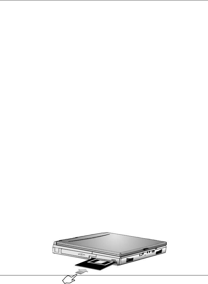
Notebook User Guide
67
Mechanical off Mode
All power, except the RTC (real time clock), has been turned off from the
system. This includes external AC power source and battery power source.
3.7 Using the FDD
The floppy disk drive (FDD) is probably one of the most used device on a
computer. Your system ships with a standard 3.5-inch 1.44-MB diskette drive
already installed in the left side of the system. The other disk drives on your
computer are the hard disk drive and the CD-ROM or DVD-ROM drive.
Disk drives are designated with drive letters with the floppy drive usually
assigned as Drive A: and the hard drive and CD-ROM or DVD-ROM drive as
Drive C: and Drive D: respectively.
The floppy disk drive (FDD) is a 3.5” diskette drive that can read and write to
high-density 1.44MB diskettes or double-density 720KB diskettes. The
diskette has an imprinted arrow on the front upper left corner, and a sliding
write-protect tab on the bottom left corner of the diskette. When opened, the
write-protect tab prevents any data from being written to or erased from the
diskette. This also protects your diskette from getting infected by virus when
used on other computers.
Insert the diskette with the arrow and label facing up and the shutter cover
towards the drive. Slide the diskette into the drive until it is totally inserted
and the eject button pops out. Remember to format new diskettes first using
your operating system.
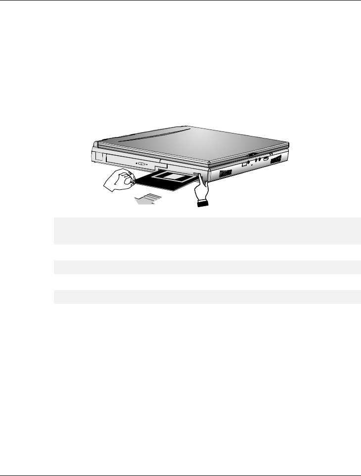
Notebook User Guide
68
To eject or remove the diskette, make sure that the system is not accessing the
diskette drive. Check the Status LED Indicator panel if the Drive Folder icon
is activated or not. If not, then press the eject button on the drive to release
the diskette.
+
Always remove the diskette whenever you are placing the notebook
computer into the carrying case for transport.
+
Always check the inserted diskette for virus before using it.
+
Always back up original diskette copies of your software programs.
3.8 Working with the Built-in HDD
Your notebook computer is equipped with a built-in large capacity 2.5 inch
IDE hard disk drive where you store or install your computer operating
system and all application software programs. The hard disk unit is located on
the left side of your computer just underneath the palm-rest panel assembly.
Like floppy diskette, you also need to format the hard disk before using. The
internal hard disk is normally assigned as Drive C after formatting. Sometimes
divided into two partitions, adding a Drive D. Since your computer supports

Notebook User Guide
69
different hard disk capacities (up to 10GB or above), you also need to setup
the disk type first on your computer’s BIOS SETUP program before
formatting the disk drive. Your computer supports Auto-detect hard disk type,
so you do not need to set it manually. Your dealer should already have done
all this for you. You can refer to Chapter 6 on how to run the BIOS SETUP
program.
You can increase the system’s storage capacity by replacing the standard hard
disk drive with a drive of greater storage capacity.
+
If you wish to replace your hard disk, contact your local dealer for more
information about this dealer-installable device.
+
Always turn off your computer first before removing the hard disk drive.
Failure to do so might damage the computer and the hard disk. Avoid
jarring or moving the computer while the hard disk is still being accessed.
3.9 How to Access the CD-ROM/DVD-
ROM Drive
Your system ships with either a 24X CD-ROM or 8X DVD-ROM drive
installed on the left side of your computer. You would normally use the CD-
ROM drive for installing operating system and software application programs.
Unlike the disk drives, you can only read from the CD-ROM drive. You also
need to install first the CD-ROM device driver before being able to access it.
Refer to Section 5 “Installing the Notebook Device Drivers” of Chapter 2 in
this manual, on how to install the driver or contact your dealer for assistance.
To insert and remove a disc on the drive:
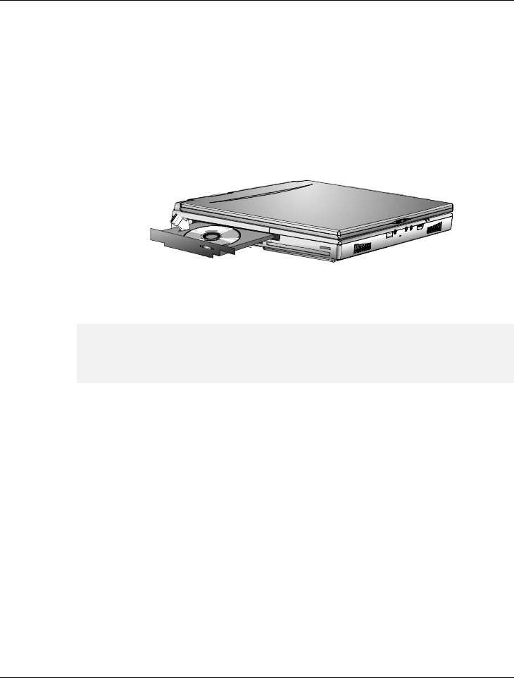
Notebook User Guide
70
1. Make sure the computer is turned on. Press the eject button found on the
door cover of the CD-ROM drive. The CD tray mechanism will pop-out
slightly and slowly pull out the whole length of the tray.
2. Place the disc on top of the CD tray with the label side facing up. Gently
press the compact disc onto the center spindle to secure the disc.
3. To remove the disc, press on the center spindle and pull up the disc from
the side until the disc snaps out of the spindle lock.
+
If the eject function is disabled by software or a power failure occurs the
Emergency Eject Hole allows you to manually remove a CD from the
reader.
4. To close the CD-ROM drive, simply push the CD tray inside. The CD-
ROM LED will activate when the disc is detected. Wait until the LED
has turned off, then start to read the disc.
How to care the CD
When you handle CDs, pay attention to the following guidelines:
• Always pick up the CD by its edges.
• Avoid scratching or soiling the side of the CD that has no printing or
writing on it.
• Do not write on or apply labels to either side of the CD.
• Keep the CD away from direct sunlight or high temperatures.

Notebook User Guide
71
• Clean fingerprints or dust from the CD by wiping it with a soft cloth.
+
The CD-ROM reader is a Class 1 Laser Product.
3.10 Using PCMCIA Cards
WHAT IS PCMCIA?
PCMCIA or Personal Computer Memory Card International Association is a
non-profit trade association and standards body composed of over 500
member companies that defines the industry standard for the PC Card
technology. The goal of PCMCIA is to ensure that any PC Card can work in
any mobile computer built with a PCMCIA slot.
A PC Card is a peripheral device that can add a wide variety of capabilities to
your computer including memory, mass-storage, LAN, fax/modem, wireless
communications, and multimedia. The PCMCIA standardized PC Card is
roughly the dimensions of a credit card, and has a standardized 68-pin
connector at one end. The main benefits of the PC Card are its low-power
consumption, small size and ruggedness.
Today, PCMCIA promotes the interoperability of PC Cards not only in
mobile computers, but in such diverse products as digital cameras, cable TV,
set-top boxes, and automobiles.
To allow manufacturers to add functions and technologies in the PC Card
form factor, PCMCIA has defined two PC Card types:
Type Thickness Sample Devices
Type II 5.0 mm Fax/Modem & Network Cards
Type III 10.5 mm Hard Disks (ATA Cards)
High-End Communication Cards

Notebook User Guide
72
Type II Cards
Type II card has a thickness of 5.0 millimeters (mm). Type II cards are often
storage or communications devices such as battery backed Static Random
Access Memory (SRAM), Read Only Memory (ROM), Flash Memory, LAN,
and Small Computer System Interface (SCSI). Typical Type II cards include
input/output (I/O) features such as modems and LANs. The features for
Type II Cards include following characters:
• Type II Extended Cards
Many PC cards are Type II extended cards. The extended card has an
additional physical component that protrudes beyond the traditional card
size. The extension can be as large as 40 mm deep by 9.65 mm high. This
extension provides room for additional electronics as well as a location
for external connectors.
• Communication Cards
Both network PC cards and fax/modem cards can use with your
notebook computer. You can insert a fax/modem in either slot. Always
insert the fax/modem card before using your fax/modem software
application. If you start the application before inserting the fax/modem
card, the application typically does not find the card.
• Storage Cards
When you insert a storage card or small hard drive card in the notebook
computer, it appears as a unique drive depending on the type of card and
the slot you are using.
The following table provides sample drive designations.
Sample Drive Designations
Drive letter Location/Device
C: Internal hard disk
D: Internal hard disk, 2nd partition

Notebook User Guide
73
Sample Drive Designations
Drive letter Location/Device
E: CD-ROM reader
F: Slot 1, IDE/ATA hard drive
G: Slot 0, high-speed memory card
H: Slot 1, high-speed memory card
Type III Cards
Type III cards are thicker (10.5 mm) than Type II cards and allow no
extensions. Type III card uses include advanced function I/O cards with
added features such as multimode cards (cards with more than one function
such as a combined modem and LAN card) and small hard drive cards.
Other Cards
Other kinds of PC cards are available to notebook computer users.
• Global Positioning System (GPS)
enable the tracking of remote units that equipped with the GPS device.
(for example, delivery trucks) This device is useful in searching city
map when driving.
• Paging
receiving remote paging messages
• Serial
adding an extra serial communications port
• Multimedia
combining animation and sound
• Video
recording, displaying, and capturing full-motion video
• Audio
enable the use of sound

Notebook User Guide
74
+
For more PCMCIA information on the Internet, visit the PCMCIA
home page at http://www.pc-card.com.
WHAT IS CARDBUS?
CardBus is the high-performance 32-bit PCI bus master interface from
PCMCIA. It runs up to 33MHz clock speed and operates at only 3.3V. Your
notebook computer incorporates the CardBus inside with a double deck
PCMCIA slot that supports one Type III card or two Type II cards at the
same time. Aside from 3.3V CardBus PC cards, you can also insert existing 5V
16-bit PC cards which can also be detected and used by your computer.
Another new type of PC card that has come out with the CardBus is the
Zoomed Video or ZV port card. See section below.
WHAT IS ZV PORT?
Zoomed Video Port or ZV Port, is an adaptation of the PCMCIA port to
allow a new type of PC card called "ZV Port Card" to be inserted into your
computer. The proposed ZV Port PCMCIA standard eliminates sending large
amounts of multimedia (video and audio) through the CPU or system bus,
allowing for much higher overall system performance during multimedia
usage. ZV Port technology is the enabling platform for the implementation of
multimedia capabilities on notebook PCs. These capabilities include: video
playback of MPEG1 and MPEG2 full motion video, video capture.
ZV Port - How it Works
With a ZV Port card inserted in your computer, compressed video data flows
from hard disk, CD-ROM, LAN or other source. Across the system bus to the
PCMCIA Cardbus controller, which passes it to the MPEG decoder in the PC
Card slot, which returns uncompressed video data back to the PC Card
controller. Using the ZV Port interface, the PC Card controller sends the

Notebook User Guide
75
uncompressed video stream directly to the video/graphics controller and to
the audio chip, and on to the display screen and speakers. In a PC without the
ZV Port interface, there is no direct connection between the PC Card
controller and the graphics controller, so the uncompressed data must wind
back through the system bus, and possibly through the CPU, to get from the
one component to the other.
+
The 32-bit card bus also has zoomed video support in the top slot only.
Also, this 32-bit structure is backward compatible, but also accepts new
cards.
SETTING UP THE PCMCIA CONTROLLER
In order for your computer to identify inserted PC cards and configure them
to work, you need first to make sure that you have the Card and PCMCIA
driver software loaded properly into your operating system.
INSERTING AND REMOVING A PCMCIA CARD
The double-deck PCMCIA slot built in at your computer supports either two
PCMCIA Type II cards at the same time or one Type II card and one Type
III card at the same time. The double-deck PCMCIA slot compartment
includes a top slot and a bottom slot. Your computer also includes hot
swapping capability, that allows you to exchange cards while the computer is
turn on and start using it immediately.
Inserting PC Cards
To insert a PC card into the PCMCIA slot:
1. Locate the PC card slot cover on the right side of the computer.

Notebook User Guide
76
2. Insert the side of PC card with the 68-pin socket into the PC slot. The
face label of the card should also be facing up. You can insert either two
Type II or one Type III card into the slots.
3. When the full length of the card is almost inside the slot, push firmly but
slowly, to ensure full connection with the computer. The PC card will be
detected and once the needed driver is installed, it will generate a beep
sound to indicate that the card is detected.
Removing PC Cards
To remove a PC card from the PCMCIA slot, you should first disable the
PCMCIA card setting in the system as described followings:
1. Click the Start button, then point to Settings, and click Control Panel.
2. Double-click on PC Card icon to appear the PC Card Properties box.
3. Select the socket from the list that you want to remove on the Socket
Status folder tab, and click Stop button. The system then disables the
function of PCMCIA card.
4. Then you can remove the inserted PC card, push the button found on the
left side of the PC slot to release the eject button. Then push it again to
release the PC card. The upper left button releases the card on the top
slot while the lower left button releases the card on the bottom slot.
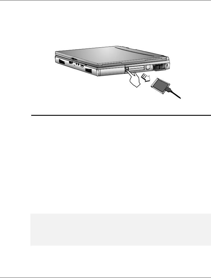
Notebook User Guide
77
5. When the PC card has moved out a space out of the slot, hold the edges
of the card and slowly slide it out.
MAKING PC CARDS WORK
Since PC cards come in different types and brands, making every card work
on your computer may not that be easy. Except for memory cards and
fax/modem cards, other PC cards like network, SCSI or multifunction cards
(MFC) need additional driver installation and configuration in making the card
work. This additional driver may already be built-in under Windows 95/98
that Windows will try to detect and prompts you if you want to install the
driver. If the driver is not included under Windows 95/98, you will need to
insert the CD-ROM driver or driver diskette provided by the PC card
manufacturer into the CD-ROM drive or floppy disk drive and install to
Windows 95/98. You need to read the manual guide of the PC card on how
to configure and operate the card.
+
Some PC cards require additional system resources. Before inserting a PC
card you may have to disable either the IR port, USB port, or the 56K
internal modem. Check the Windows 98 device manager to ensure that one
of these devices is disabled before inserting a PC card.

Notebook User Guide
78
HOT SWAPPING PC CARDS
Just like floppy disk drive, your PCMCIA slots allow you to replace one PC
card with another even while your computer is on. However, you need to
remember the rule that if the PC card is in use, you must not remove it.
Below are some examples on how to handle PC cards when hot swapping:
• Do not remove a network card while your system is connected to the
network.
• Do not remove fax/modem card while the card is transferring data into
or from your computer.
• Do not remove a hard disk or ATA card while your computer is
accessing the card.
To remove PC cards under Windows 95/98 while the computer is on, you
need to stop the PC card device first under the PC Card properties box.
Follow these steps:
1. In the Control Panel, double-click on PC Card (PCMCIA). If there is a
PC card icon on your Windows taskbar, you can also click on it to
immediately go to the PC Card properties box.
2. Click on the PC card you want to remove and click Stop.
3. Wait until your system has prompted you that the PC card can already be
removed.
+
PC cards draw power even when not in use. To save energy, press the
button to disconnect the card when it is not in use. You can leave the card
in the slot while it is disconnected for easy storage.

Notebook User Guide
79

Notebook User Guide
80