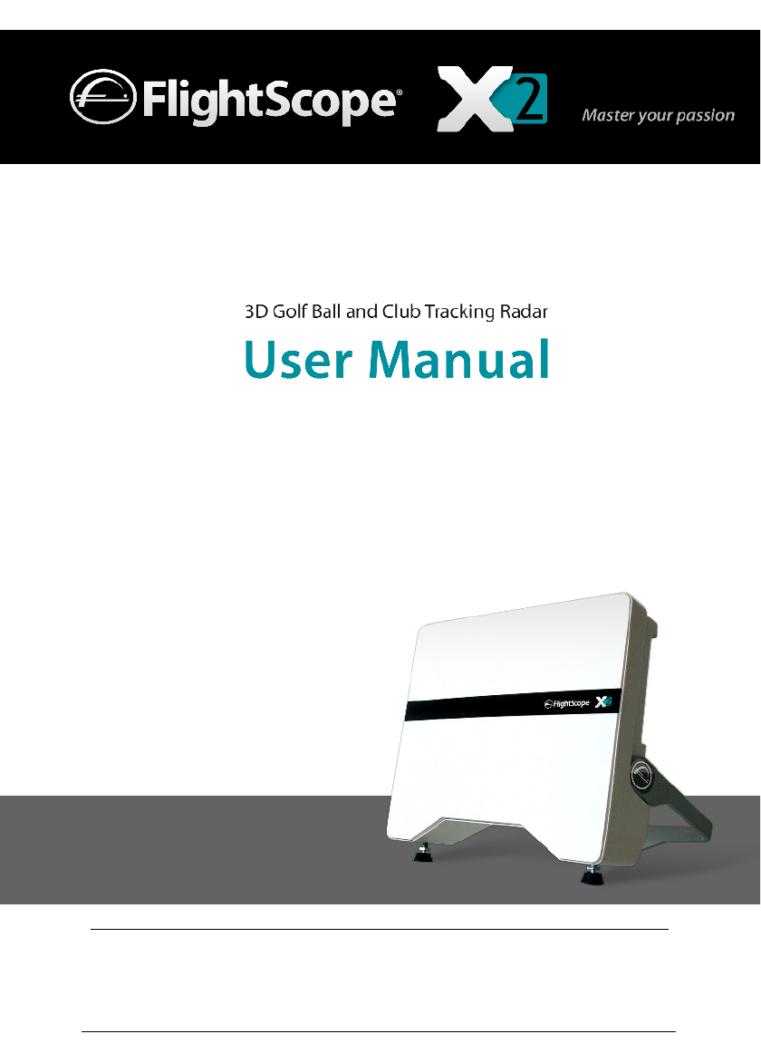
FlightScope PT238 Sports equipment motion measuring sensor User Manual 1
FlightScope (Pty) Ltd Sports equipment motion measuring sensor 1
Contents
- 1. User Manual 1
- 2. User Manual 2
User Manual 1

Rhein Tech Laboratories, Inc.
Client:
EDH (South Africa) (Pty) Ltd
360 Herndon Parkway
Model:
FlightScope X2
Suite 1400
Standards:
FCC 15.245/IC RSS-210
Herndon, VA 20170
http://www.rheintech.com
FCC/IC ID:
QXP-PT238/4612A-PT238
Report #:
2011040
Page 23 of 29
Appendix J: Manual
Please see the following pagesIRU3DUWRIWKHPDQXDO3DUWLVVXEPLWWHGLQDVHSDUDWHILOH.
Doc No. E19-WA082 Issue A5.7
COPYRIGHT NOTICE:
The information presented in this document may not be copied or reproduced in any form whatsoever
without the prior written consent of EDH. EDH reserves all rights to the information published this
document. Title of the information and any copies thereof shall remain the property of EDH. No
proprietary, copyright, confidential, or other proprietary rights, legend or markings may be removed
from any part of this document.
Inside Front Cover

FlightScope User Manual
Copyright EDH 2007-2011 E19-WA082 Issue A5_7
Page i
GENERAL AND SAFETY NOTICES
Summary
The following notices and general safety precautions must be observed during the
operation, service and repair of this equipment. Failure to comply with these precautions
or with warnings elsewhere in the manual violates standards of the design, manufacture
and intended use of the equipment. EDH accepts no liability for failure to comply with
these notices.
Operation of the device in any country may require approval in accordance
with local telecommunications and safety regulations.
Sheltered and Clear Weather Use Only
The equipment has been designed for sheltered or in clear weather use and must not be
used outdoors under rainy conditions.
FCC Statement
Changes or modifications not expressly approved by EDH (South Africa) (Pty) Ltd could
void the user's authority to operate the equipment.
This equipment has been tested and found to comply with the limits for a Class B digital
device, pursuant to part 15 of the FCC rules. These limits are designed to provide
reasonable protection against harmful interference in an office or residential installation.
This equipment generates, uses and can radiate radio frequency energy and, if not
installed and used in accordance with the instructions, may cause harmful interference
to radio communications. However, there is no guarantee that interference will not occur
in a particular installation. If this equipment does cause harmful interference to other
electronic equipment, which can be determined by turning this equipment off and on,
the user is encouraged to try to correct the interference by one or more of the following
measures:
• Increase the separation between the equipment causing and experiencing the
interference
• Install a radio frequency shield between the equipment causing and
experiencing the interference
• Consult your dealer for help
This device complies with Part 15 of the FCC Rules. Operation is subject to the following
two conditions:
• this device may not cause harmful interference, and
• this device must accept any interference received, including interference that
may cause undesired operation.

FlightScope User Manual
E19-WA082 Issue A5_7 Copyright EDH 2007-2011
Page ii
IC Statement
This device complies with Industry Canada Rules for license-exempt radio devices.
Operation is subject to the following conditions: (1) the device may not cause harmful
interference, and (2) the device must accept any interference received, including
interference that may cause undesired operation.
Déclaration IC
Le présent appareil est conforme aux CNR d'Industrie Canada applicables aux appareils
radio exempts de licence. L'exploitation est autorisée aux deux conditions suivantes : (1)
l'appareil ne doit pas produire de brouillage, et (2) l'utilisateur de l'appareil doit accepter
tout brouillage radioélectrique subi, même si le brouillage est susceptible d'en
compromettre le fonctionnement.

FlightScope User Manual
Copyright EDH 2007-2011 E19-WA082 Issue A5_7
Page iii
Table of Contents
Introduction .............................................................................................. 8
Getting Started........................................................................................ 10
System Components ............................................................................. 10
Setting up the sensor ........................................................................... 11
Position ............................................................................................ 11
Ground Surface................................................................................. 11
Handle ............................................................................................. 11
Leveling ........................................................................................... 11
Placing the Sensor ................................................................................ 12
Hooking up the cables .......................................................................... 13
USB Cable Connection ....................................................................... 13
Power Supply Connection .................................................................. 13
Switching On and Off ........................................................................... 14
Switching On .................................................................................... 14
Switching Off - Normal ...................................................................... 14
Switching Off - Forced ....................................................................... 14
Power Supply and Batteries ...................................................................... 15
Using the system with AC supply ........................................................... 15
Batteries.............................................................................................. 15
Battery life ....................................................................................... 15
Specification of battery cells ............................................................... 15
Charging the batteries ....................................................................... 16
Batteries run down ............................................................................ 16
Inserting or removing batteries .......................................................... 16
Resetting the battery charge level monitor .......................................... 17
Installing PC Software .............................................................................. 18
Prerequisites ........................................................................................ 18
Installation Procedure ........................................................................... 18
Installing Apple Device Software ............................................................... 19
Prerequisites ........................................................................................ 19

FlightScope User Manual
E19-WA082 Issue A5_7 Copyright EDH 2007-2011
Page iv
Installation Procedure ........................................................................... 19
Wireless Connections ............................................................................... 20
Wireless Network (WiFi) Connection ....................................................... 20
Setting up the WiFi connection – first time use .................................... 20
WiFi connection - next time use .......................................................... 20
PC Operation ........................................................................................... 22
Running the software............................................................................ 22
Setup Wizard ....................................................................................... 23
Step-by-step procedure ..................................................................... 23
Re-alignment .................................................................................... 28
Daily Start-up ....................................................................................... 30
Club Comparison .................................................................................. 32
Starting a Session ............................................................................. 32
Playing Shots .................................................................................... 35
Screen Navigation ............................................................................. 39
Driver Optimizer ................................................................................... 40
How it works .................................................................................... 40
Graphs ............................................................................................. 41
Player Comparison ................................................................................ 48
Play..................................................................................................... 50
Ball Comparison ................................................................................... 52
Ball Comparison ................................................................................ 52
Ball Fitting Centre ............................................................................. 52
Publishing reports ................................................................................. 56
What can be published ...................................................................... 56
Publish options ................................................................................. 56
Label Printing.................................................................................... 60
Sensor Status Indicators ....................................................................... 62
USB Port Status ................................................................................ 62
Connection Status ............................................................................. 62
Ready/Idle........................................................................................ 63
Battery Level .................................................................................... 63
Tooltips ............................................................................................ 63
Club Type and Roll/Tilt indicator: ........................................................ 63

FlightScope User Manual
Copyright EDH 2007-2011 E19-WA082 Issue A5_7
Page v
User Manual ........................................................................................ 64
Advanced Settings ................................................................................ 66
Sensor ............................................................................................. 66
Networking....................................................................................... 67
Sessions ........................................................................................... 67
Display ............................................................................................. 68
Altitude ............................................................................................ 69
Surface ............................................................................................ 69
Publishing ........................................................................................ 69
Add-ons ........................................................................................... 69
Help ................................................................................................ 69
Connecting a Video Camera .................................................................. 74
Prerequisites .................................................................................... 74
Hooking up the camera ..................................................................... 74
Switching on the Video Capture mode ................................................ 74
Configuring the Video Capturing ......................................................... 74
Operating the video system ............................................................... 76
Playback of video clips ....................................................................... 77
Setting up “Extended Desktop Mode” ..................................................... 78
Connecting a second monitor ............................................................. 78
Setting FlightScope to display on the second monitor ........................... 78
Setting up additional FlightScope Screens ............................................... 80
Setting FlightScope to display on the second monitor(s) ....................... 80
Server settings ................................................................................. 80
Client settings ................................................................................... 80
Software Activation .............................................................................. 82
Operation with Apple Tablets and Smart Phones ........................................ 88
Running the software ........................................................................... 88
Settings ............................................................................................... 90
Session ............................................................................................ 90
Club Select ....................................................................................... 93
Player Select .................................................................................... 93
Ball Select ........................................................................................ 93
Sensor Firmware Updating ....................................................................... 94

FlightScope User Manual
E19-WA082 Issue A5_7 Copyright EDH 2007-2011
Page vi
Spin Measurement ................................................................................... 98
Definition of Parameters ......................................................................... 100
System Specifications ............................................................................. 102
Description ........................................................................................ 102
System Functions ............................................................................... 102
Club Comparison ............................................................................. 102
Player Comparison .......................................................................... 102
Ball Comparison .............................................................................. 102
Play ............................................................................................... 102
Technical capabilities .......................................................................... 103
Physical characteristics ........................................................................ 103
Dimensions ..................................................................................... 103
Mass .............................................................................................. 103
Environmental Specifications ............................................................... 104
Ambient temperature: ..................................................................... 104
Ingress protection: .......................................................................... 104
Electrical characteristics ...................................................................... 104
Earthing ......................................................................................... 104
Requirements for Outdoor Installations ................................................ 104
PC and other device Specifications .......................................................... 106
Maintenance and Troubleshooting ........................................................... 108
Basic Care ......................................................................................... 108
Rear Panel LED Indicators ................................................................... 109
Status LED ..................................................................................... 109
Connected LED ............................................................................... 109
Charging LED .................................................................................. 110
Frequently Asked Questions (FAQ) .......................................................... 112
Index ................................................................................................... 116

FlightScope User Manual
Copyright EDH 2007-2011 E19-WA082 Issue A5_7
Page 7
Blank Page
FlightScope User Manual
E19-WA082 Issue A5_7 Copyright EDH 2007-2011
Page 8
I
NTRODUCTION
Congratulations on purchasing FlightScope
®
, the world’s first-ever 3D
Doppler tracking radar for golf.
FlightScope measures how a player hits golf balls, providing information
about the player and the equipment (clubs and balls).
Here are a few examples of what FlightScope can do:
Test clubs and balls to find the best equipment for a player
Measure performance of a player
Golf instruction
Calibrate golf clubs in a player’s bag
Compare performance with other players including top golfers
Evaluate personal progress
Provide instructional and entertaining data about golf shots not
known to most golfers
Research on club and ball performance
As a professional club fitter or golf instructor you can measure the
performance and progress of a player and his/her equipment accurately and
scientifically, find the best equipment fit, and evaluate progress.
As a player, you will be able to go out onto the course knowing your yardage
and shot making capabilities. This will improve your scores and enjoyment of
the game.

FlightScope User Manual
Copyright EDH 2007-2011 E19-WA082 Issue A5_7
Page 9
Blank Page
FlightScope User Manual
E19-WA082 Issue A5_7 Copyright EDH 2007-2011
Page 10
G
ETTING
S
TARTED
Before FlightScope can be used, the sensor and other hardware and software
must be installed.
System Components
Your X2 system needs either a PC/Notebook computer or a handheld device
such as a smartphone or pad to install and use FlightScope.
The components included with the system are:
Sensor Unit
USB Cable
AC Adapter
Mains Power Cord
Software on CD
User Manual
Carry Case
The system is intended for use with a PC, notebook computer, or certain
tablet or smart phone devices. See section on PC and other device
Specifications for details of compatible devices.
FlightScope User Manual
Copyright EDH 2007-2011 E19-WA082 Issue A5_7
Page 11
Setting up the sensor
Position
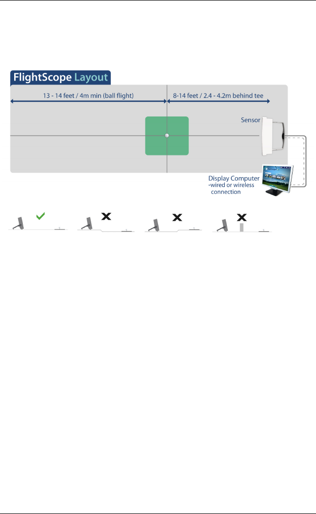
The sensor must be placed between 2.4 to 4 meters (8 to 14 ft.) behind the
tee.
Ground Surface
The sensor should be used on a level surface, (grass, carpet, or hard floor).
Handle
CAUTION
The handle is locked in position by spring loaded
plungers. Release the plungers before moving
the handle. Do not force the handle while locked.
Release the handle by sliding the two thumb sliders inwards to release the
spring loaded pins that lock the handle position. At the same time pull the
handle backwards.
When free, move the handle to the “down” position. The spring loaded pins
will again lock the handle in the down position.
In the down position, the handle acts as the rear support for the sensor.
Leveling
The sensor should be set up with no roll (sideways angle) and tilted at the
optimum angle of approximately 10 degrees (leaning backwards).
The X2C model has a built-in automatic leveling mechanism that will adjust
the sensor to the correct roll and tilt angles for operation.
Other X2 models do not have automatic leveling: in this case the sensor roll
and tilt angles must be set manually by adjusting the feet of the sensor
and/or by modifying the work surface to achieve the correct sensor angles.
FlightScope User Manual
E19-WA082 Issue A5_7 Copyright EDH 2007-2011
Page 12
Placing the Sensor
NOTES
Use FlightScope on a level surface. There must
be no obstructions in front of the sensor.
FlightScope User Manual
Copyright EDH 2007-2011 E19-WA082 Issue A5_7
Page 13
Hooking up the cables
CAUTION
Ensure that connectors are inserted with the
correct orientation.
The connectors are keyed to ensure that they are
inserted correctly. Do not force the connectors
when inserting.
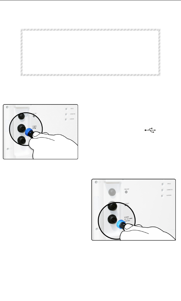
USB Cable Connection
Insert the Communications Cable
(USB) to your PC and connect the
other end to the COMMS connector
marked with the symbol .
Insert the connector and fasten the
nut lightly.
Power Supply Connection
Insert the AC Adapter connector
into the Power connector on the
rear of the sensor.
The connector is keyed and can
only be inserted one way.
Insert the connector and fasten
the nut lightly.

FlightScope User Manual
E19-WA082 Issue A5_7 Copyright EDH 2007-2011
Page 14
Switching On and Off
Switching On
NOTE
The FlightScope X2 On/Off switch is inhibited if the
handle is in the upright (carry) position, to prevent
accidental battery drain. The sensor can only be
switched on when the handle is released and partly or
all the way down.
Switch the sensor on by pushing the On/Off pushbutton on the rear panel.
A brief Push-then-Release action is needed.
When switched on, the Status LED indicator lamp will light up and blink. See
LED Indicator states below.
Switching Off - Normal
Switch the sensor off with a brief push and release of the On/Off pushbutton.
The sensor will shut down gradually starting by retracting the feet and also
performing other shutdown procedures.
The Status LED indicator will turn Blue while the shutdown is in progress,
and be off when the shutdown is completed.
Switching Off - Forced
To force rapid switch-off, push and hold the On/Off pushbutton. When the
button has been held for more than 1 second, the sensor will shut down
immediately, not retracting the feet.
Use this mode only if needed. The feet cannot be pushed in manually and
this form of shutdown will cause the feet to be extended and will not fit the
carry case.
All LED indicators will be off when completed.

FlightScope User Manual
Copyright EDH 2007-2011 E19-WA082 Issue A5_7
Page 15
P
OWER
S
UPPLY AND
B
ATTERIES
Using the system with AC supply
The system can be connected to an AC supply (100-240 V AC single phase)
instead of battery power. This can be done at any time.
Connect the AC adapter to the sensor’s 12V DC input connector, and to a
mains outlet.
Batteries
WARNING
The product uses Nickel Metal Hydride (NiMH)
rechargeable batteries.
Do not use other battery types rechargeable or
not (e.g. Alkaline, NiCd, Mercury, etc.) as this
may lead to malfunction, damage, or explosion.
CAUTION
Batteries contain hazardous chemicals that pose
a health risk if not used or disposed of in a
proper manner.
Do not expose batteries to extreme heat.
Do not puncture or open battery cells.
Discard old batteries in accordance with your
local waste regulations.
Battery life
Battery life depends on the battery cells' specified capacity, age, and charge
state (level) when switching on. With cells of 10,000mAh capacity at full
charge, the sensor can typically operate for at least 8-10 hours before
requiring recharging.
Specification of battery cells
The FlightScope X2 is powered with 6 rechargeable 1.2V D-size Nickel Metal
Hydride (NiMH) cells. Cells with capacity of 10,000mAh are recommended.

FlightScope User Manual
E19-WA082 Issue A5_7 Copyright EDH 2007-2011
Page 16
Charging the batteries
NOTE
Batteries and charging circuits generate heat when
being charged. It is normal that parts of the sensor will
become warm while charging batteries.
Connect the AC adapter (power supply unit), disconnect the computer from
the sensor, and switch the sensor on (push button switch). The sensor will
start up in the standby mode (Status LED blinks blue)
Charging will start if the batteries are run down fully or partially. The amber
Charging LED will blink when charging is in progress.
The Charging LED will stop blinking (off) when the batteries are fully
charged. Charging time is typically 14-18 hours, depending on the battery
state.
NOTE
If a computer is connected to operate the FlightScope,
battery charging will be interrupted.
Batteries run down
When the batteries run down, the sensor Status LED indicator will blink RED
as a low battery warning. When this occurs, connect the AC adapter to
continue using, or charge the batteries. Otherwise, the system will shut down
after a few minutes.
Inserting or removing batteries
NOTE
Battery cells should be replaced when they reach end of
life (e.g. when they do not hold charge any more).
Replace batteries with new NiMH cells of the same
capacity from the same manufacturer.
Ensure that new batteries are “conditioned” by pre-
charging them independently to full capacity in an
external NiMH battery charger before inserting.
First, open the battery compartment. Undo the screw beneath the sensor
that holds the battery cover in place. Then slide the battery panel down to
remove. Remove the cells from the cell holders, taking care to correctly
orientate the cells according to the indicated polarity direction for each cell
location.

FlightScope User Manual
Copyright EDH 2007-2011 E19-WA082 Issue A5_7
Page 17
Replace new, reconditioned NiMH cells in the cell holders, taking care that all
the cells are placed with the correct polarity orientation. With the cells
securely in place, replace the cover, and fasten the battery cover screw
(bottom).
Resetting the battery charge level monitor
If the batteries are inserted for the first time, or removed and inserted for
any reason, the battery charge level monitor circuit may not be able to
determine the charge state of the batteries accurately.
To reset the monitor, proceed as follows:
• Switch the sensor on (connected to a computer but no AC adapter
connected) and let the batteries run down completely. This will be
when the sensor status indicator starts to bling “blue” or goes off
completely.
• Now, connect the AC adapter, disconnect computer, and switch on
the power button to start charging. Amber Charging LED will light
up. Leave to charge for around 14 hours continuously. At the end of
charge, the amber Charging LED indicator turns off.
The system can now be used normally, and the charge level monitor will be
correctly set.
FlightScope User Manual
E19-WA082 Issue A5_7 Copyright EDH 2007-2011
Page 18
I
NSTALLING
PC
S
OFTWARE
Prerequisites
Any recent Laptop, Notebook, or Desktop Computer with processor
speed of 1 GHz or more, and with 1 GByte memory, CD/DVD ROM drive,
and at least one USB interface port;
Microsoft
®
XP, Vista or Windows 7 operating systems;
FlightScope installation software (on CD).
Installation Procedure
Switch Computer on and wait for operating system to start up.
Insert FlightScope CD into the computer’s CD/DVD ROM drive. The
installation software will start automatically.
Follow the steps and instructions provided by the installation
software. Press “Next” when asked and accept “default” options if
unsure about any selection.
Once the installation is complete, remove the CD from the computer
and store it in a safe place.
If the default options were selected, the FlightScope software will
be available as an Icon on the computer’s Windows Desktop.
FlightScope User Manual
Copyright EDH 2007-2011 E19-WA082 Issue A5_7
Page 19
I
NSTALLING
A
PPLE
D
EVICE
S
OFTWARE
FlightScope software for mobile iDevices (manufactured by Apple, Inc. e.g.
iPad or iPhone) must be downloaded from the Apple iTunes App Store,
category Sports.
Prerequisites
An iPhone, iPod touch, or iPad manufactured by Apple, Inc., with operating
software iOS 3.0 or later.
You must also be registered with Apple iTunes application store, and have an
Apple ID for App Store purchases.
Installation Procedure
Find and press the App Store icon
Enter your Apple ID
Use the SEARCH function to search for FlightScope applications
Select the FlightScope application, and when you are sure of the
selection, press the “purchase” button to request and download the
application to your iDevice.
The download and installation will proceed. When completed, the
software is ready to run.
FlightScope User Manual
E19-WA082 Issue A5_7 Copyright EDH 2007-2011
Page 20
W
IRELESS
C
ONNECTIONS
Wireless Network (WiFi) Connection
NOTE
This connection can be used with PC’s or devices with
WiFi capability (IEEE 802.11b/g). Ask your PC or device
vendor or consult its manual to find out if your
PC/device is WiFi capable.
FlightScope X2 can connect to your PC/device wirelessly, without any cable
connection, by means of Wireless Network connection (WiFi).
Setting up the WiFi connection – first time use
Before the WiFi connection can be used, it has to be set up by following your
PC/device’s wireless network setup procedures.
1. Switch the FlightScope X2 on (USB cable NOT CONNECTED).
2. On a Windows PC, run the tools for setting up a
Wireless Network. E.g. right-click the icon (right) on
the toolbar, Scan for available networks and
connect to the visible FlightScope unit.
3. On Apple devices, run the Apple Settings App (the
tool for managing wireless network connections) (see
icon). Set Wi-Fi ON. Choose a network – FlightScope.
Scroll down for FlightScope – ensure Radar Device
Direct Connection is ON. Switch On if necessary.
Once the connection is established, the FlightScope program will display
“Connected” status and the system can be used.
WiFi connection - next time use
If the PC/device has been connected to the X2 by wireless network before, it
will automatically connect to the X2 when both are switched on.
If the PC/device has been set up to connect to more than one wireless
network, the prevailing priority settings could make the PC/device connect to
another network on startup, instead of the FlightScope. If this happens, you
can connect to the FlightScope manually by using the PC/device’s Connection
Management tools, and manually “Connect” to the X2. After this the
FlightScope software will detect and use the WiFi network connection.
If desired, you can modify the priority list of your PC/device’s wireless
connections to make FlightScope X2 the top choice.

FlightScope User Manual
Copyright EDH 2007-2011 E19-WA082 Issue A5_7
Page 21
Blank Page
FlightScope User Manual
E19-WA082 Issue A5_7 Copyright EDH 2007-2011
Page 22
PC
O
PERATION
Running the software
The FlightScope software has been designed for “ease of use”.
Ensure that the sensor power is switched on. (The sensor may be left
permanently powered on)
• Place the Computer near the Sensor within reach of the
Communications Cable (USB) (if used). Connect the cable to the
Sensor as well as a USB port on the Computer, and start up the
Computer OR
• If used wirelessly, make sure the wireless connection is working.
• Click the FlightScope icon on the desktop to start the software.
o If the computer is connected to the internet, the software
checks at startup if a newer software version is available.
This automatic check can be disabled (F10->Help->”Check
for updates on startup”)
o Updates can also be forced by F10->Help->”Check for
updates”
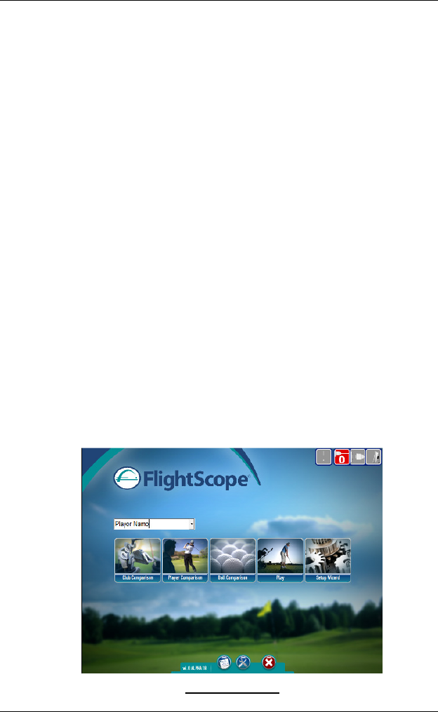
• On the Main screen the following selections are available:
o Club Comparison, Player Comparison, Ball Comparison, Play
mode, and Setup Wizard
• The following additional controls are available at the bottom of the
screen: User Manual, Advanced Settings and Exit
Startup Screen
FlightScope User Manual
Copyright EDH 2007-2011 E19-WA082 Issue A5_7
Page 23
Setup Wizard
NOTE
Do set-up at least the first time the system is
used.
The Setup Wizard is a step-by-step procedure to be followed before using the
FlightScope. It can be skipped if the set-up remains unchanged between use
events (e.g. if it is a fixed hitting cage installation), but must be updated if
the set-up changes (e.g. if the system is used at different locations).
The Setup Wizard can be started from the Main screen menu or from the
Advanced Settings (F10) menu.
NOTE
Follow all Setup Wizard steps to set the system correctly.
Step-by-step procedure
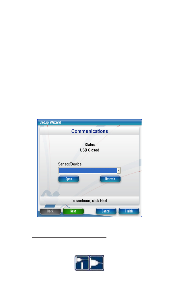
Setup 1. Connect the sensor to the PC and power on.
Setup 2. Click Open to select the sensor to connect to. Click Refresh to
update list of devices connected.
When the sensor is successfully connected the Port Status and Sensor Status
on the top right of the screen icons will appear dark blue as follows:
Click Next to proceed.
FlightScope User Manual
E19-WA082 Issue A5_7 Copyright EDH 2007-2011
Page 24
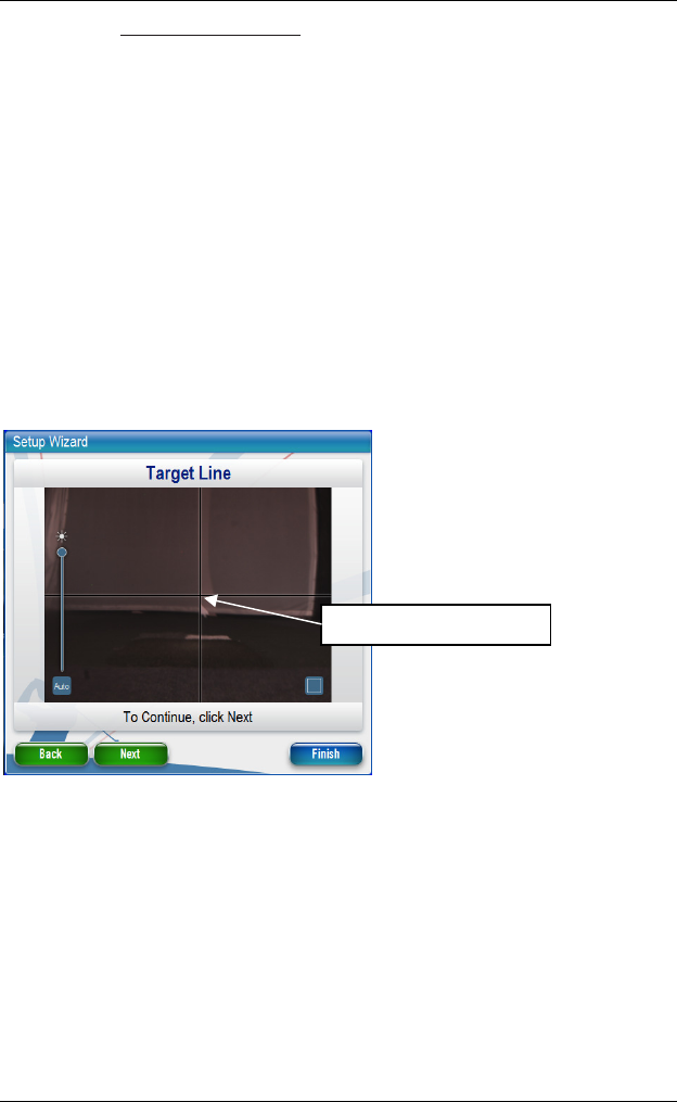
Setup 3. Align target direction
This step registers the direction of the target to compensate for slight sensor
pointing error.
NOTE
Applies only to X2 systems
fitted with Alignment Camera
Adjust slider if necessary to compensate for low or bright conditions.
The cursor lines will appear in the center of the picture, indicating where the
sensor is pointing:
Identify the desired target in the picture (e.g. flag, tree or other object that
marks the target line), and drag the cursor lines on to the target.
Click Next to accept and proceed.
Cursors on Target Line
FlightScope User Manual
Copyright EDH 2007-2011 E19-WA082 Issue A5_7
Page 25
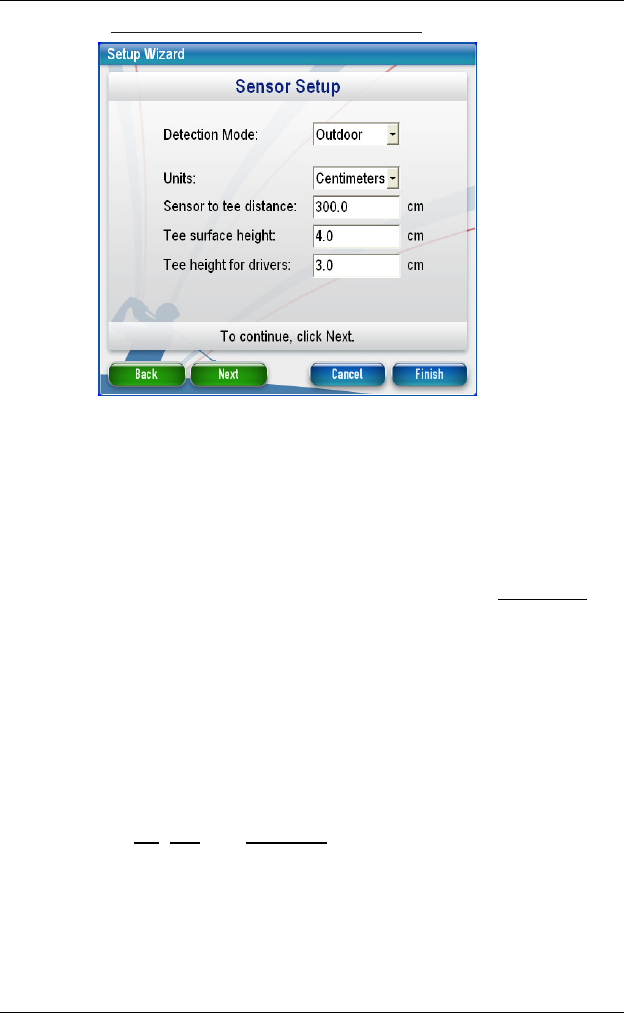
Setup 4. Set up the sensor mode and geometry.
Set the Detection Mode to Indoor if the system is used indoors e.g. in a
hitting cage with limited ball travel distance. Set to Outdoor mode if
hitting outdoors e.g. on a driving range or golf course.
Choose the Units of measurement (Metric or Imperial) for the hitting
geometry.
Enter the Sensor to Tee distance, which is from the tee/hitting spot to
the sensor face.
Enter the Tee surface height which is the height of the tee surface
(
not the Ball Tee itself
) above the surface on which the FlightScope is
placed.
The height of the ball tee, used with a Driver, can be specified in
addition in the Tee height for Drivers field. This value is used when
the club type is specified as “Driver”. For other clubs, this height is
assumed to be 0 (zero).
Press Next to continue.
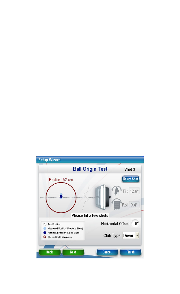
Now, adjust the Tilt, Roll, and Ball Origin. This step will ensure that your
sensor correctly orientated and points in the right direction.
The wizard will indicate roll (sideways angle) and tilt (forward/backward
angle). Roll angle must be between +0.5 and -0.5 degrees, and tilt angle in
the range from 10-13 degrees.
Adjust the sensor feet to correct the roll and tilt angles.
FlightScope User Manual
E19-WA082 Issue A5_7 Copyright EDH 2007-2011
Page 26
Then adjust the pointing direction. For this the ball needs to be hit from a
position within a 52 cm (20 in) radius from the sensor’s expected tee
position. As a rule the ball origins (blue dots) will be near the center of the
red circle if the sensor pointing direction is more or less correct.
Select the club type to use for the test (iron, driver or wedge).
Then hit a 3 or 4 shots with the ball placed each time as closely as possible
on the chosen tee position.
The ball origin for each shot is displayed as a blue dot. The most recent shot
will be a dark while earlier shots are displayed in a lighter shade.
The displayed origins should overlap. An outlier shot can be rejected (“Reject
Shot”)> Further test shots can be played if desired.
The Horizontal Offset value (the pointing direction offset) is displayed. This
value should be approximately 0 (zero).
HINT
Get this value small to reduce lateral (sideways)
ball tracking errors. Horizontal Offset of 1˚
causes 2.5 meters sideways error at 150 meter
distance; 0.2˚ offset adds only 0.5 meters error.
The pointing direction can be corrected by slight clockwise or
counterclockwise rotation of the sensor, after which the test must be
repeated to verify the Horizontal Offset.
The “Ball Origin” can be checked at any time during system operation from
the Advanced Settings menu (F10 > Sensor > Ball Origin).
FlightScope User Manual
Copyright EDH 2007-2011 E19-WA082 Issue A5_7
Page 27
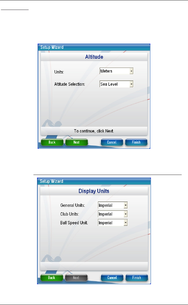
Set Altitude
Choose the units for altitude (meters or feet).
Select the correct altitude (Sea Level, Medium or High). A custom value
can be set by selecting the Custom option in the Altitude Selection list and
entering the desired height above sea level in meters or feet.
Press Next to continue.
Setup 5. Select the units of measurement for data (Metric or Imperial).
To complete the setup, press Finish.

FlightScope User Manual
E19-WA082 Issue A5_7 Copyright EDH 2007-2011
Page 28
NOTE
FlightScope allows different units of
measurement to be selected for Club, Ball
Speed, and General (other) data, to meet
different international practices and needs.
The system is now ready for use.
Re-alignment
If you move the FlightScope and want to set up in different location, you
have to set up the sensor geometry for the new location. Run the Setup
Wizard and repeat at least Setup 3 as described in the Setup Wizard above.

FlightScope User Manual
Copyright EDH 2007-2011 E19-WA082 Issue A5_7
Page 29
Blank Page

FlightScope User Manual
E19-WA082 Issue A5_7 Copyright EDH 2007-2011
Page 30
Daily Start-up
Check/confirm that the sensor is switched on (LED flashing) and is in the
correct position.
Start the software.
Check that the PC/device is connected to the sensor.
Select or enter the name of the player. A new player’s name will be saved for
future data retrieval.
Select the mode to use: Club Comparison, Player Comparison, Ball
Comparison, or Play.

FlightScope User Manual
Copyright EDH 2007-2011 E19-WA082 Issue A5_7
Page 31
Blank Page
FlightScope User Manual
E19-WA082 Issue A5_7 Copyright EDH 2007-2011
Page 32
Club Comparison
Starting a Session
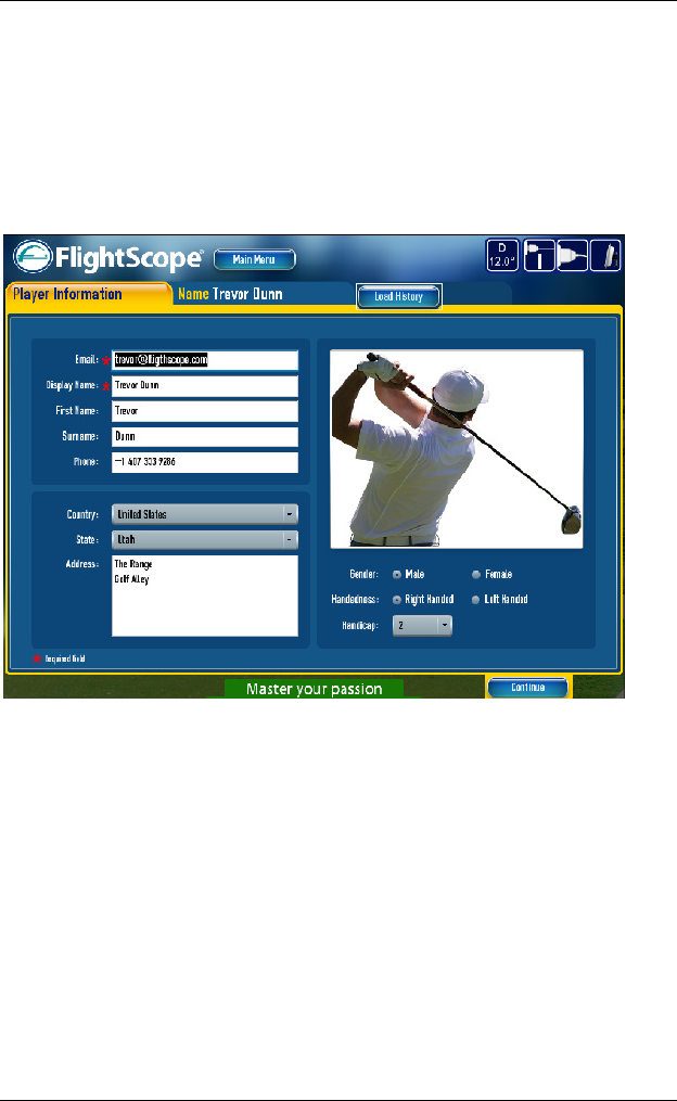
Click on Club Comparison to test and compare clubs.
On the Player Information screen, enter a new player’s data, or check correct
an existing player’s data. If this is up to date, this test’s results can be added
to the global FlightScope golf database that you will be able to access.
Press Continue to proceed.
FlightScope User Manual
Copyright EDH 2007-2011 E19-WA082 Issue A5_7
Page 33
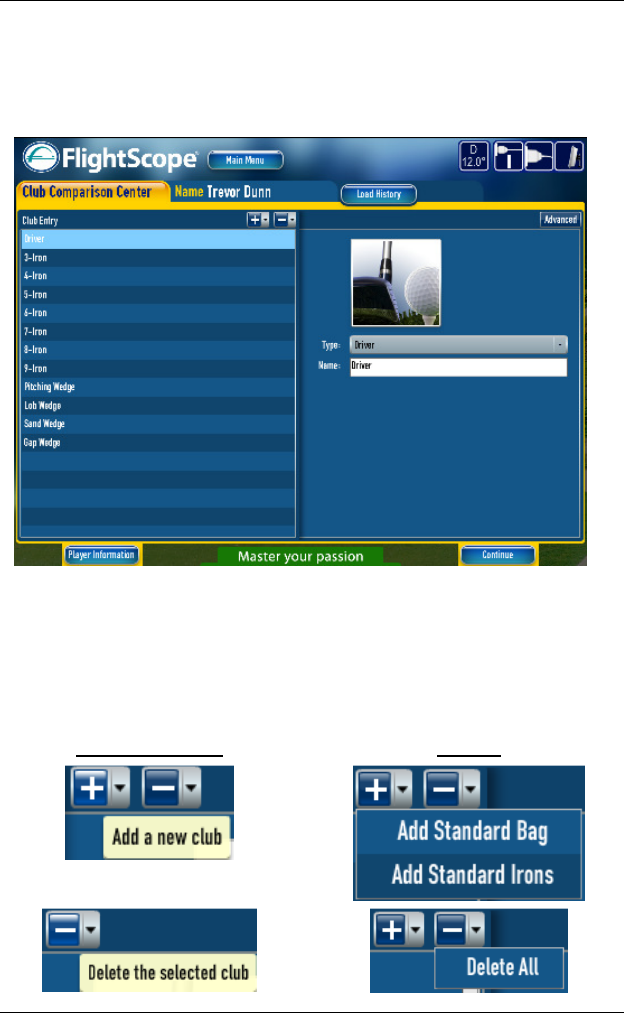
In the Club Comparison Center screen, enter the clubs to be tested.
For each club, set the type (Driver, Iron, or Wedge) for correct handling of
club types. It is typical to compare similar clubs (e.g. Drivers, or 7-Irons),
although it is also possible to set up to measure the performance different
club types (e.g. of each club in a players bag).
After clubs are entered, their names can be edited by selecting the club in
the left hand column, and typing the desired name in the “Name:” box on
the right hand side. Confirm the name change using “Enter”.
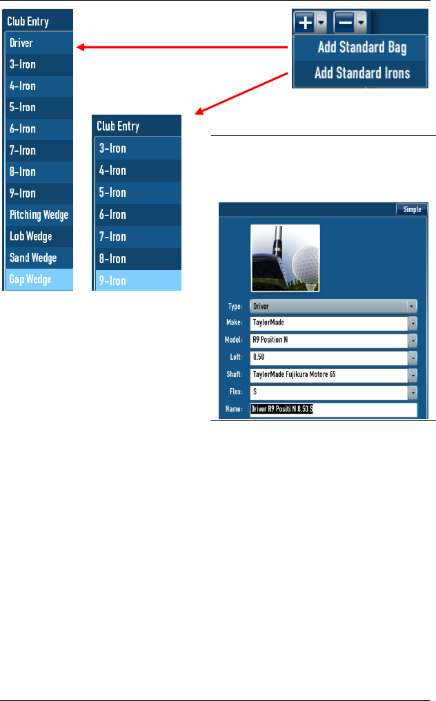
For convenience, clubs can also be added individually or as groups. Add
either a standard bag, or standard irons.
Delete All or the club selected.
Individual Clubs Groups
FlightScope User Manual
E19-WA082 Issue A5_7 Copyright EDH 2007-2011
Page 34
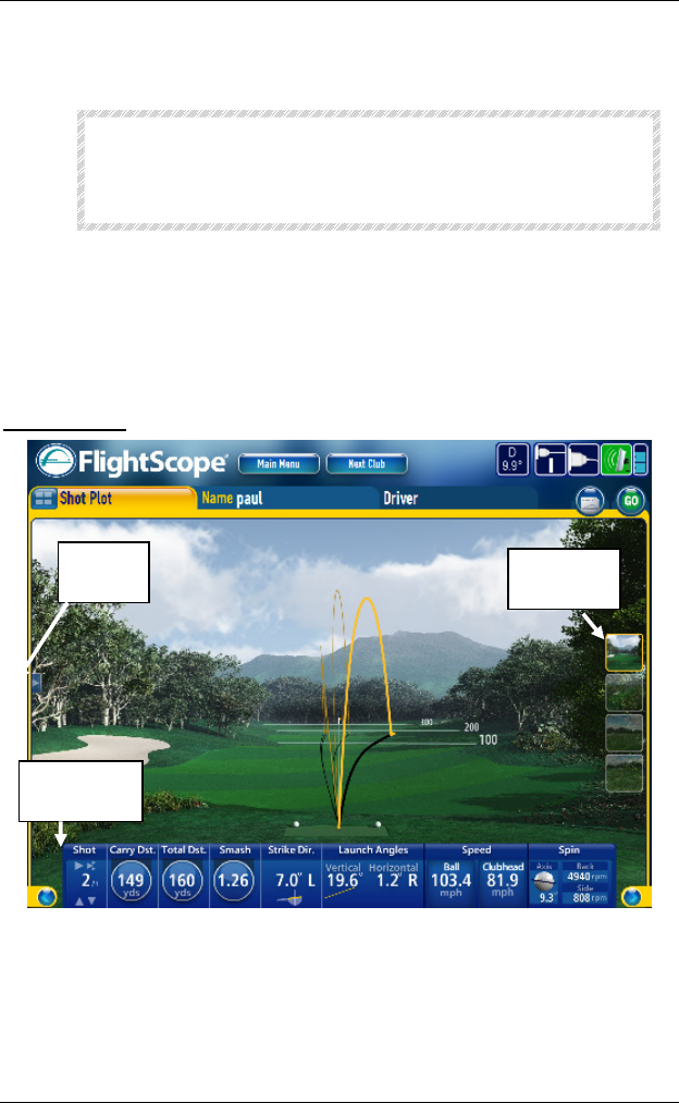
The Advanced tab provides more
assistance with club definitions, e.g.
to select/add club details
(type/make/model/loft/shaft/flex).
To go back to edit Player Information, click on the button so named.
Click on Continue to start club comparison.
FlightScope User Manual
Copyright EDH 2007-2011 E19-WA082 Issue A5_7
Page 35
Playing Shots
CAUTION
Always check that Player and Club displayed on
the screen corresponds with the actual player
and club, so that data is correctly captured.
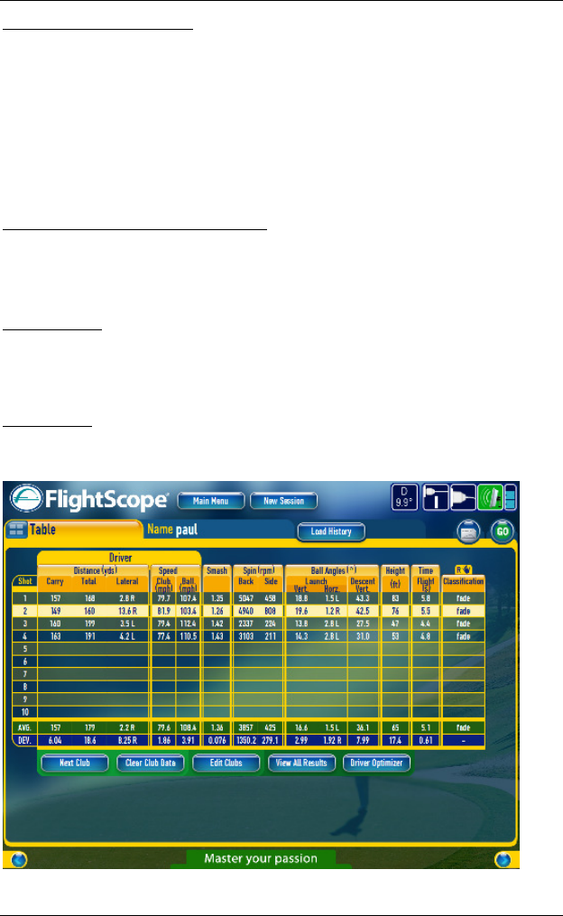
The session opens by default on the 3D shot plot screen.
Step to other screens by clicking the < or > arrows on the lower left and
right of the screen, or by using the Left/Right keyboard arrows.
3D Shot Plot
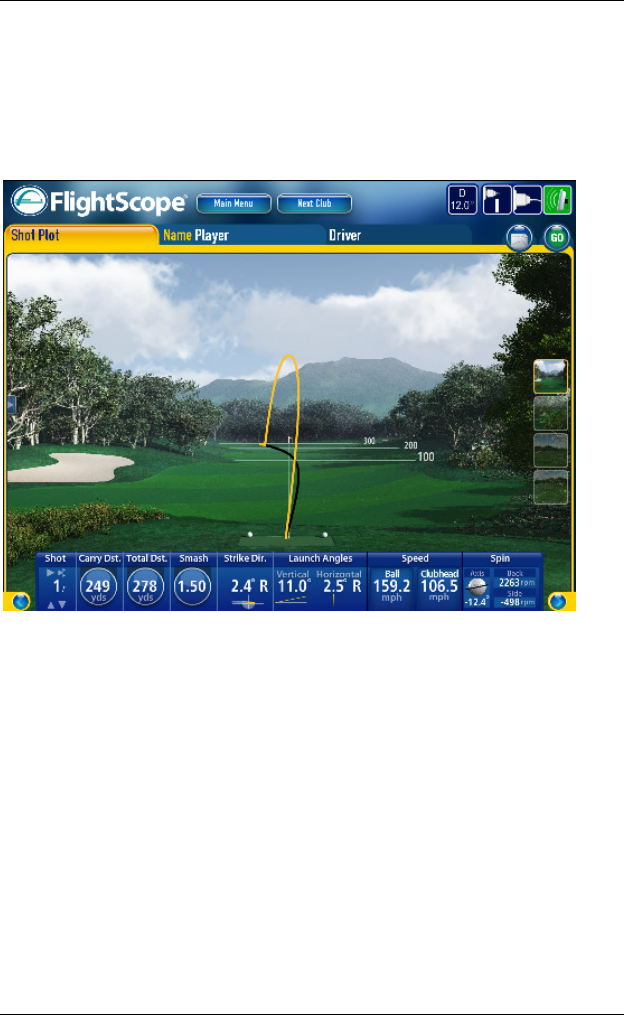
The 3D Shot Plot screen displays shot trajectories in a 3 dimensional view.
The key club and ball data for each shot is displayed on the screen, with the
plot of the ball flight path.
Clubs
List
View
Select
Shot No.
button
s
FlightScope User Manual
E19-WA082 Issue A5_7 Copyright EDH 2007-2011
Page 36
Navigation through shots: Step through all shots for a particular club by
means of the Up/Down keyboard arrows, or by clicking on the up/down
arrow icons on the screen.
A chosen shot can be replayed (animated) by pressing the
button above
the Shot Number, or by pressing the keyboard Space bar.
All shots can be replayed (animated) by pressing the button above the
Shot Number, or by pressing Ctrl+Space on the keyboard.
Golf Course or Driving Range Display: Click the icons on the right hand side
of the screen to display measurements in aspect view or from behind on a
Golf Course or Driving Range.
Club selection: On the left edge side of the display is a button that opens a
list of clubs being used. Select a different club to display its data. Minimize
the list if not needed.
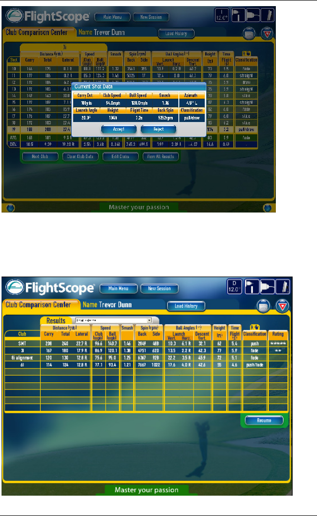
Table View
The Table View displays a list of measurements for each club, as well as
running averages and deviations.
You can play as many shots with each club as you choose.
FlightScope User Manual
Copyright EDH 2007-2011 E19-WA082 Issue A5_7
Page 37
Basic Controls:
Navigate between shots with the mouse or up/down arrows.
Use the DEL key to remove a shot from the test data (it becomes grayed
out). Press DEL again to bring it back.
CAUTION
If a shot’s data is permanently deleted,
it cannot be recovered.
Press SHIFT+DEL to delete a shot permanently.
Select the next club to play with, or scroll between clubs using Next Club.
The “Next Club” button will display data of the next club in the sequence (if
available).
Clear Club Data will erase data from the table.
Edit Clubs will return to the club entry screen where club names and types
can be modified or further clubs can be added if required.
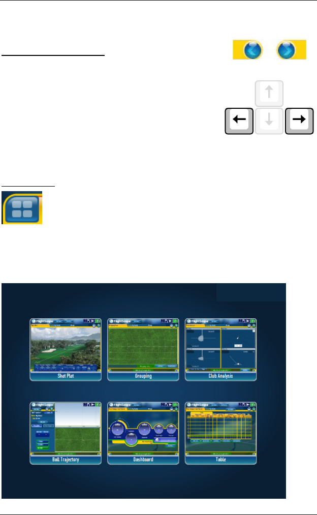
To view comparative results between measured clubs measured, click on
View all results.
Manual Shot Acceptance:
By default the system accepts every shot.
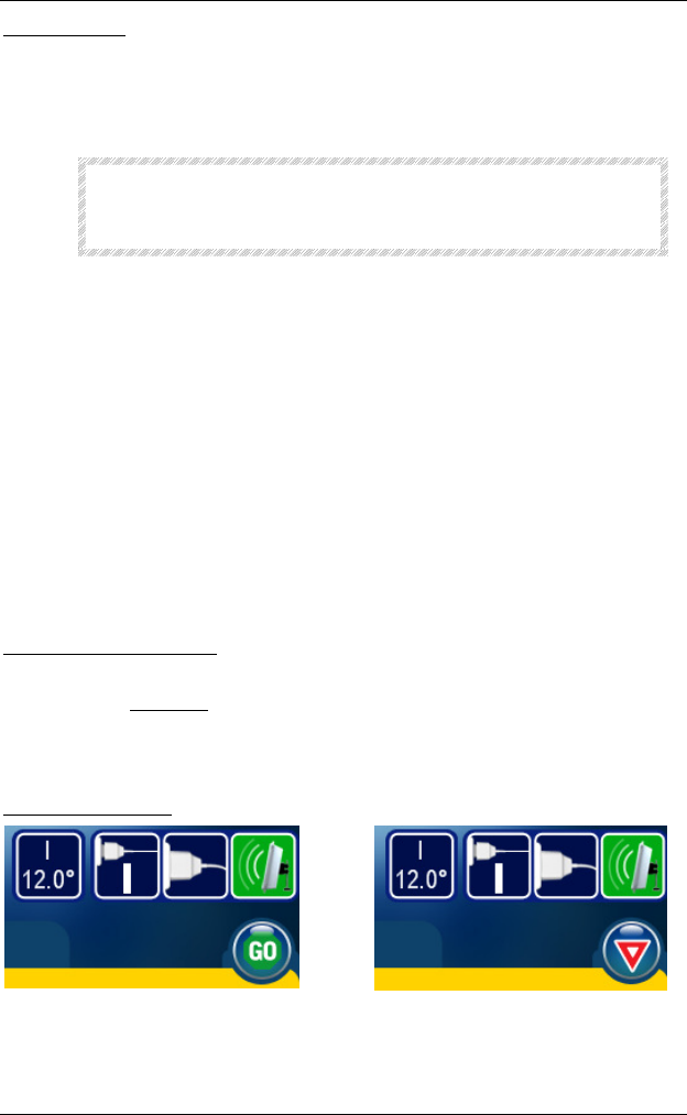
If you wish to manually Accept or Reject shots, for example for pre-emptive
elimination of poor shots, click on the GO button (see left hand figure
below). It will then change into a YIELD button (see right hand figure
below). You will then be prompted to Accept or Reject each shot manually.
Go/Yield Button:
FlightScope User Manual
E19-WA082 Issue A5_7 Copyright EDH 2007-2011
Page 38
Accepted shot data will be saved to a file on the computer.
View all results table:
In this view you can rate clubs according to various criteria.
Results can also be printed.
Click Resume to return to return to the Table View.
FlightScope User Manual
Copyright EDH 2007-2011 E19-WA082 Issue A5_7
Page 39
Screen Navigation
Basic Screen Selection
While playing in the Club Comparison mode, you
can scroll between the Shot Table and other views
including: Dashboard, Grouping, 3D Shot Plot, Club
Analysis, Ball Trajectory, and Tracking Info by
clicking on the navigation buttons (see right),
or
by pressing the left and right arrow buttons on the
keyboard (see right).
Screen Map
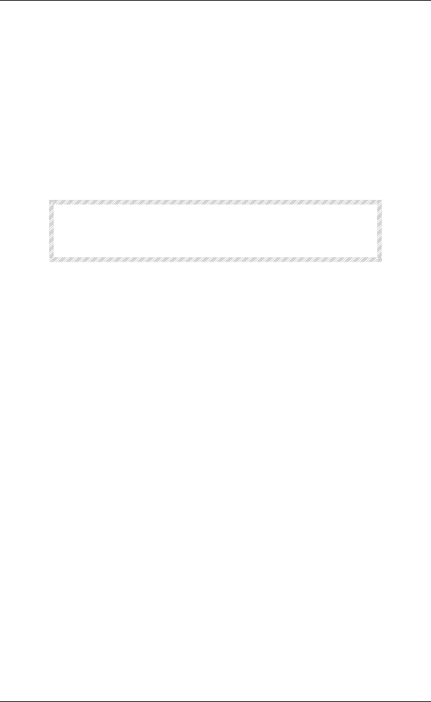
All working screens are just 2 clicks away with FlightScope’s
Screen Map.
To move to a new screen, simply click the Screen Map icon
(top, left), and the Screen Map (below) will appear.
Select a screen, and click. The selected screen will open.
FlightScope User Manual
E19-WA082 Issue A5_7 Copyright EDH 2007-2011
Page 40
Driver Optimizer
The Driver Optimizer button will be visible if the club type is set to
“Driver”. This function is described in more detail in the following section.
The FlightScope Driver Optimizer determines the LAUNCH ANGLE and BALL
SPIN that will produce the longest carry distance (alternatively total distance)
for a particular player.
The Driver Optimizer can be selected from the Club Comparison mode (see
section on Club Comparison).
Optimization can be done for either carry distance or total distance.
CAUTION
To be used for fitting DRIVERS only.
Not suitable for irons and wedges
How it works
STEP 1 - Using any driver, the player plays a set of typically 3-6 shots to
provide a statistical sample of his performance with the club.
STEP 2 - Inspect the shots to determine if there were any problem shots
(e.g. out-of-pattern readings). Delete (DEL key) all outliers from the shot
records.
STEP 3 - Select the DRIVER OPTIMIZER function. The OPTIMIZER screen will
display a graph and associated data.
NOTE
Driver Optimizer assumes player can achieve
a smash factor of 1.50
NOTE
Driver Optimizer uses a “medium” surface
hardness to determine the optimum
distances
FlightScope User Manual
Copyright EDH 2007-2011 E19-WA082 Issue A5_7
Page 41
Graphs
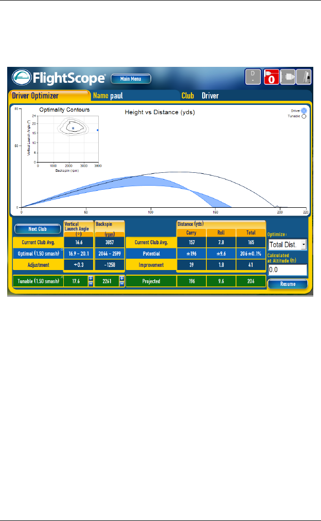
The graphs show the calculated Optimum trajectory for the player. A colored
band shows the envelope of trajectories of the shots played. If more than
one driver was tested, select them in turn by Next Club.
The user can select to optimize for Carry or Total Distance, for which the
Launch Angle and Spin values will be calculated.
The screen shows:
Average spin and launch angle of the shots played
Optimum spin and launch angles
Potential carry (or total) distance
Adjustments to spin and launch angle to achieve optimum distance
Resultant optimum distance (carry and total)
Form (or shape) of the trajectory
A graphic tool for viewing the actual spin and launch angle relative to
the optimum
Controls to tune spin and launch angle values relative to the optimum
Spin and launch angles can be adjusted in the text boxes or by clicking
on a position in the contour graph.

FlightScope User Manual
E19-WA082 Issue A5_7 Copyright EDH 2007-2011
Page 42
The “o” symbol shows the optimum and the “x” marks the adjustable
point
The user can tune the spin rate or the launch angle for which a
corresponding “best” trajectory will be calculated. The resultant distance
(carry and total) as well as the shape of the resulting trajectory is shown.
Play-offs can be made between spin and launch angle combinations, carry
distance and total distance for the player, helping to gain an understanding
of sensitivity of the carry or total distance to launch angle and spin.
FlightScope User Manual
Copyright EDH 2007-2011 E19-WA082 Issue A5_7
Page 43
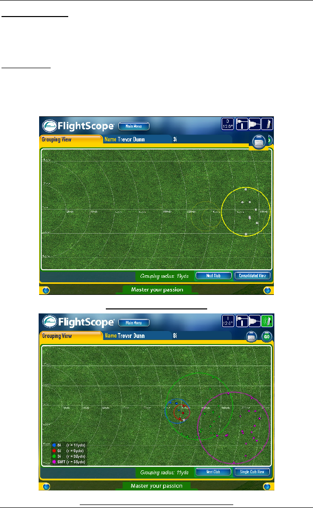
Grouping View
The Grouping view displays the grouping of the ball landing positions and
the grouping radius. Either Single Club or Consolidated View (all clubs) can
be selected.
Zoom in/out: The PC mouse or touchpad can be used to zoom in or out on
this screen. Zoom in by holding down the left hand mouse/touchpad button
while making a clockwise movement with the pointer. Zoom out by holding
down the left hand mouse/touchpad button while making a counter-
clockwise movement with the pointer.
Grouping of a Single Club
Consolidated Grouping view – all clubs
FlightScope User Manual
E19-WA082 Issue A5_7 Copyright EDH 2007-2011
Page 44
Club Analysis View
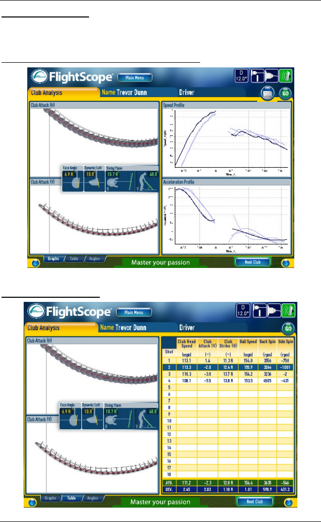
Three screens are available in this view:
Graphs: Club Trajectory, Speed and Acceleration
Table: with Club Graphs
FlightScope User Manual
Copyright EDH 2007-2011 E19-WA082 Issue A5_7
Page 45
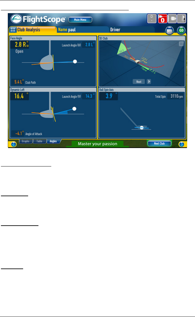
Angles: Club Face, Loft, 3D Club, and Ball Spin Axis
Club Attack Angle This is the direction the clubhead is traveling with
respect to the ground at the moment of impact with the ball. A negative
value indicates a club traveling downward and a positive angle indicates a
club traveling upward.
Club Path This is the swing path of the club at the moment of impact with
the ball. It is measured relative to the target line. The angle is displayed with
an indication of R (Right) for in-to-out movement and L (Left) for out-to-in
movement.
Dynamic Loft This is the effective loft with which the ball is struck,
combining the club loft and the club path and attack angles, that causes
actual ball launch which is the result of the swing path of the club at the
moment of impact with the ball. It is measured relative to the target line. The
angle is displayed with an indication of R (Right) for in-to-out movement and
L (Left) for out-to-in movement.
3D Club This displays the movement of the clubhead in an arc in the swing
plane, relative to the ground. The swing plane vertical angle and the direction
of the swing plane at the position as well as the ball direction at the moment
of ball impact are displayed.
Choose between various views e.g. “3D”, Side, Top, or Rear.
The club movement is animated (press to play).
FlightScope User Manual
E19-WA082 Issue A5_7 Copyright EDH 2007-2011
Page 46
Ball Trajectory View
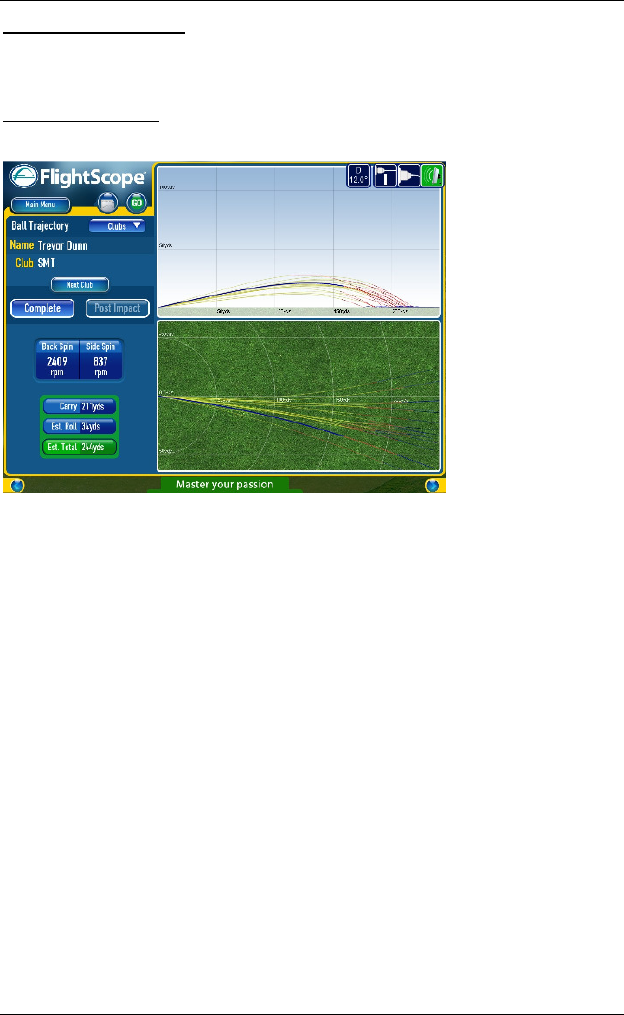
This displays the ball trajectory in side and top views, with additional data.
The estimated roll, based on the selected surface type, is added.
Complete trajectory
Shows the real time trajectory of the golf ball in side and top views, to scale.
NOTE
All shots in a
session, by club
or combined,
can be displayed
for comparisons
of shots e.g.
trajectory or
distance.
NOTE
Tracking the final part of the ball trajectory requires strong “tracking
filtering”. The measurements provide a trajectory estimate which is displayed
as a dotted line.
FlightScope User Manual
Copyright EDH 2007-2011 E19-WA082 Issue A5_7
Page 47
Dashboard View
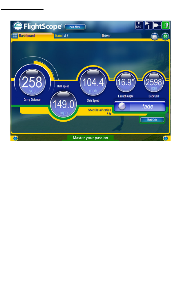
The Dashboard view displays the results of a single shot in large format.
FlightScope User Manual
E19-WA082 Issue A5_7 Copyright EDH 2007-2011
Page 48
Player Comparison
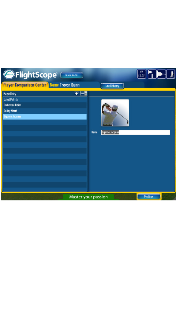
Player Comparison follows the same layout and procedure as Club
Comparison but allows the performance of different players to be compared.
Start by selecting “Player Comparison” on the main screen.
Enter the names of two or more players to compare. Type name in box
and hit enter to add a player. Use + - (also delete all) to adjust the
player list. Press Continue to proceed.
Allow each player in turn to play a selection of shots. This will usually be
with the same or similar club. Each player will attempt to repeat his
shots as closely as possible to get a good statistical sample of his
performance.
During each player’s turn, any unwanted shots can be deleted. This can
also be done after all players have completed their turns.
After all players have completed their shots, the detailed results of each
player can be reviewed to detect any unrepresentative shots. These can
be deleted temporarily or permanently from the data.
Finally, the All Results screen can be used to view the comparative
statistics of the players.

FlightScope User Manual
Copyright EDH 2007-2011 E19-WA082 Issue A5_7
Page 49
Blank Page
FlightScope User Manual
E19-WA082 Issue A5_7 Copyright EDH 2007-2011
Page 50
Play
Play mode is a simple and effective way to use FlightScope. You do not
need to set up a session. You can play shots immediately.
When you select Play, your player name is “Player”.
Select a “Driver”, “Iron” or “Wedge”, by pressing Next Club.
You can add clubs if required.
However if you need to save the results under a particular player’s
name, it is recommended to use the “Club Comparison” mode instead.

FlightScope User Manual
Copyright EDH 2007-2011 E19-WA082 Issue A5_7
Page 51
Blank Page