Fountain People 0000020 Water Playground Central Controller Transmitter User Manual pt 1
Fountain People Inc. Water Playground Central Controller Transmitter pt 1
Contents
- 1. user manual pt 1
- 2. user manual pt 2
user manual pt 1
© 2008 FOUNTAIN PEOPLE, INC.
version 1.2
The DSC series
Dynamic Sequencing Controller
(for Aquatic Playgrounds)
© 2008 Fountain People, Inc.

© 2008 FOUNTAIN PEOPLE, INC.
version 1.2
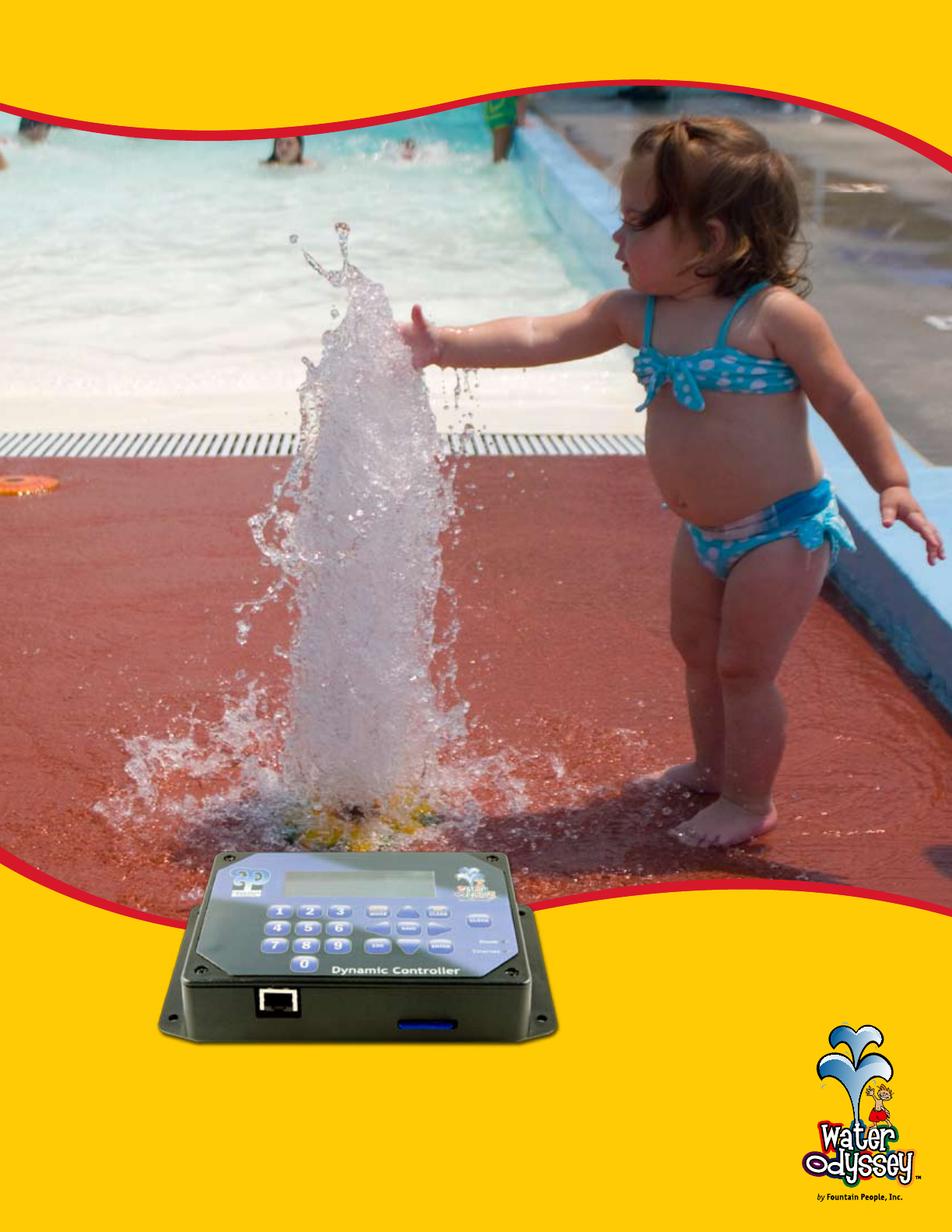
Water Odyssey™
Dynamic Sequencing Controller
This manual is intended to acquaint the user with both installation
of the DSC and the procedures for modifying the various settings
responsible for the behavior of the aquatic playground.
The DSC ....................................................................... 2-6
Concept .................................................................................. 2
Advantages .............................................................................. 3
Features .................................................................................. 4
Component Identification ........................................................ 5-6
Quick Start .................................................................7-19
Installation Documents ......................................................... 8-10
Basic Operation .................................................................. 11-16
System Tests ...................................................................... 17-19
Aquatic Playground ................................................... 20-26
What is an Aquatic Playground? ............................................ 20-22
Modifying Events ................................................................ 23-26
1
FCC ID: WIM0000010
This device complies with part 15 of the FCC Rules. Operation is subject to the following two conditions: (1) This device
may not cause harmful interference, and (2) this device must accept any interference received, including interference
that may cause undesired operation.
FCC ID: WIM0000020
This device complies with part 15 of the FCC Rules. Operation is subject to the following two conditions: (1) This device
may not cause harmful interference, and (2) this device must accept any interference received, including interference
that may cause undesired operation.
IC-7978A-0000010
This Class [A] digital apparatus complies with Canadian ICES-003.
Cet apparelj numériqué de la classe [A] est conformé à la norme NMB-003 du Canada
IC-7978A-0000020
This Class [A] digital apparatus complies with Canadian ICES-003.
Cet apparelj numériqué de la classe [A] est conformé à la norme NMB-003 du Canada
Warnings:
Any changes or modifications to of the printed circuit board of this equipment could void the user’s authority to operate
the equipment. Operation of an unapproved antenna circuit could void the user’s authority to operate the equipment.
Water Odyssey™ devices by Fountain People Inc. may be used in the United States of America and Canada under one or
more of the following identifiers:
FCC ID: WIM0000010, IC:7978A-0000010
FCC ID: WIM0000020, IC:7978A-0000020

© 2008 FOUNTAIN PEOPLE, INC.
version 1.2 2
Concept
Aquatic Playgrounds create a stimulating interactive play environment
for children. The operational control of these play areas has evolved.
Prior to the introduction of the DSC Series Controller an aquatic playground’s
control system was commonly comprised of time clocks, timers, Programmable Logic
Controllers (PLCs), sequencers and a lot of wire.
This equipment was wired together according to the individual aquatic playground’s
design requirements. For example, if an aquatic playground required two time clocks
and three sequencers, the control panel would consist of two time clocks and three
sequencers. Not only is this design limited in its ability to add interactivity to an
aquatic playground, it is difficult to modify the programming and often requires
assistance from the manufacturer.
© 2008 FOUNTAIN PEOPLE, INC.
version 1.2
Inputs (select one or many)
8 Additional Terminals per Module 9
32 Wireless Activators 9
7 Different Time Clocks 9
Outputs (select one or many)
8 Additional Terminals per Module 9
Advantages
The DSC controller was designed specifically for aquatic play
applications. It is reliable, flexible, and easy to reprogram in
the field or in the comfort of your office on a PC.
With the DSC base module you have the equivalent
of 60 time clocks, 60 timers, 60 cycle timers, 30
sequencers, and logic control all in one easy to
program package! The “wiring” of these components
is performed by selecting and setting event properties
in the DSC.
Events are the programming equivalent of wiring
equipment together. Basically, an event is a list of
options that determine what will start a water feature,
how a water feature will behave, how long a water
feature will run and lastly what wire terminal will
power the water feature. The following table lists a
few the available choices for every event.
The DSC allows up to 60 user changeable events. The options for each event are accessible through the DSC by
using the integral keypad and LCD display.
With the DSC, you can easily upgrade your aquatic playground, add new features, add new activators, or just
change the Play Scenario™ of the aquatic playground anytime you want. No more waiting on the manufacturer
to return your call.
Dynamic Controller
Functions (select one)
Duration Timer 9
Cycled On/Off Timer 9
Defined Sequence 9
Random Output 9
Event Cue 9
3

© 2008 FOUNTAIN PEOPLE, INC.
version 1.2 4
Features
The DSC controller is highly versatile and has a wide range of
capabilities. Becoming familiar with these capabilities will help you
to understand how to apply them to your aquatic play area.
Interface Control Module
Each system is shipped with a detailed drawing set unique to the project.•
Built in operating hours that you can set for each weekday. (in 15 minute increments)•
A Play Scenario™ is preprogrammed, essentially making your aquatic playground ready for operation •
once installation is complete.
Input and output terminal blocks are removable, allowing for easy wiring. •
Terminal blocks are spring loaded and include a wire installation tool.•
The output voltage is 24VAC.•
WaterScript™ is a Microsoft® Windows® based program that makes programming the DSC even easier •
with its simple to use drag and drop interface.
Activators
Eight wired inputs per module.•
Integral support for up to 32 Wireless Activators.•
Wireless activator addresses are field adjustable.•
Seven types of time clock activators ranging from hourly to specific time and weekday.•
Event Functions
Duration: Turn on water features for a set period of time.•
Cycled: Cycle water features on and off for a set period of time.•
Random: Cycle random water features on and off at random rate.•
Defined: Turn water features on based on a user defined pattern.•
Event Cue: Cycle through multiple events with one activator.•
Built in Diagnostic Tests
Test wired inputs to ensure they are wired to the correct activator•
Test wireless inputs to confirm their addresses and check for low batteries.•
Test outputs to ensure they are wired to the correct water feature.•
Test individual events to ensure that they behave the way you expect.•
© 2008 FOUNTAIN PEOPLE, INC.
version 1.2
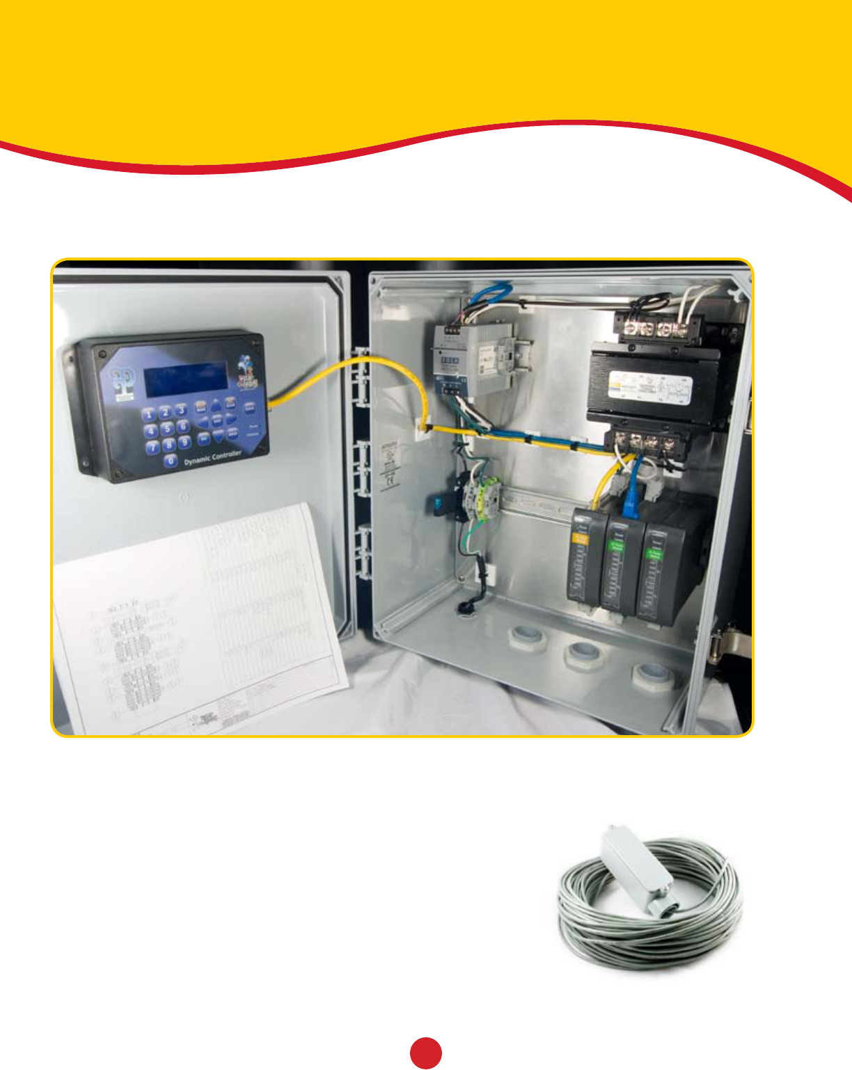
Panel Components
The image below illustrates the basic components found in a DSC panel.
Use this as a reference for information discussed later in the manual
Wireless Receiver
A wireless receiver and 150’ of shielded cable are supplied if your system uses
wireless activators. The receiver will need to be installed and the cable must
be connected to the a port on the Communication Bus inside the DSC panel.
Reference the electrical drawings included with your system.
IMPORTANT: The receiver should be installed at least 10 feet
above grade, no more than 150 feet from the furthest activator,
and within line of sight of all the activators. (See wireless
installation parameters drawing)
5
© 2008 FOUNTAIN PEOPLE, INC.
version 1.2 6
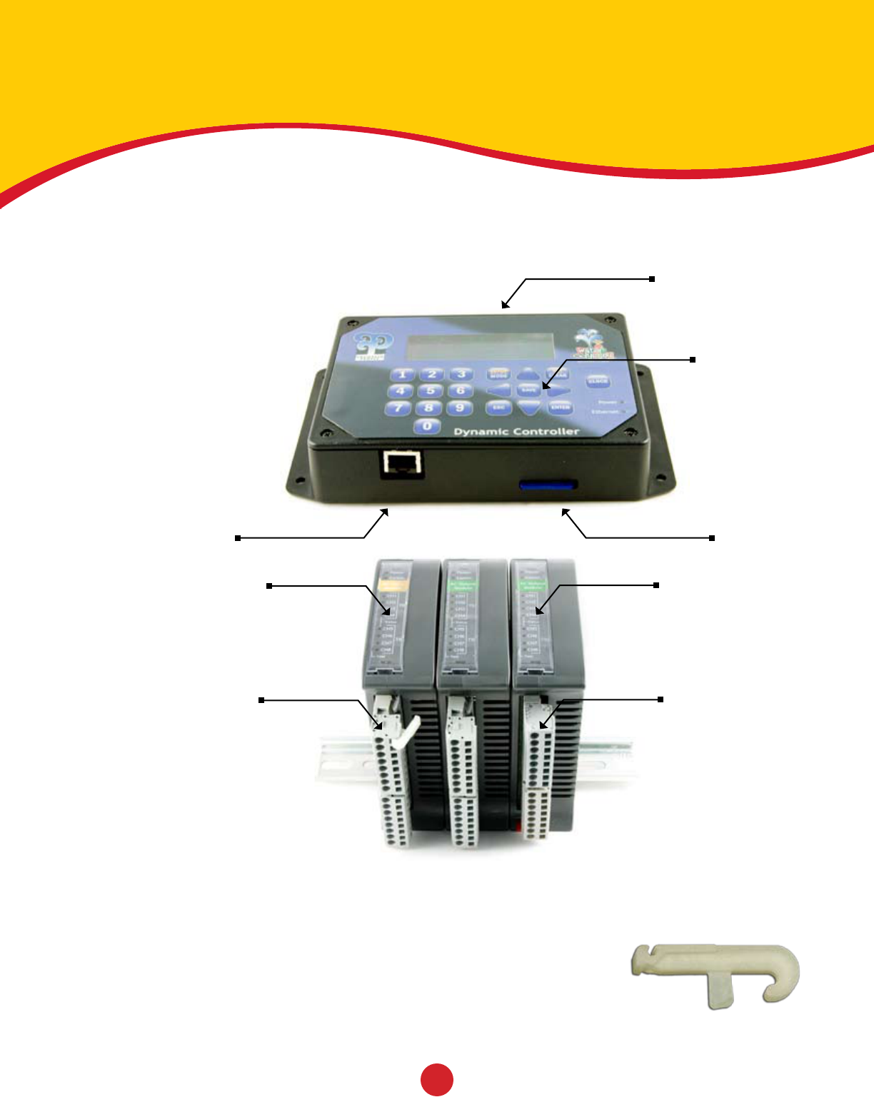
DSC Components
The image below identifies the basic components found on the Main Module of a
DSC panel. Use this as a reference for information discussed later in the manual.
Wire Installation Tool
There are two tools attached to the terminal blocks. These tools can be
removed and placed over the terminal you are wiring. After removing the
terminal plug, snap the installation tool on the desired terminal and press
down on the tool while supporting the terminal plug. The spring terminal
will open allowing easy connection of each wire. When the wiring is
complete, plug the terminal block into the DSC.
DSC Display
Navigation Keys
SD Card
AC Wired Output
Indicators
DC Wired Input
Indicators
(Wireless Systems do not
require DC Input modules)
AC OutputsDC Inputs
Ethernet Port

© 2008 FOUNTAIN PEOPLE, INC.
version 1.2
Quick Start
This section contains information to assist in understanding your project’s
installation documents, basic operation of the DSC, and system testing.
Installation Documents ............................................... 8-10
Included Documentation ......................................................... 8-9
Piping and Wiring Verification ................................................... 10
Basic Operation .......................................................... 9-16
Main Screen and Keypad ........................................................... 11
Menu Navigation ..................................................................... 12
Adjust the Date and Time ......................................................... 13
Adjust the Operating Hours ....................................................... 14
Add a Password ....................................................................... 15
Change the Clock Mode ............................................................. 16
System Tests ............................................................ 17-19
Activators .............................................................................. 17
Test Outputs .......................................................................... 18
Checking Solenoid Valves ......................................................... 19
7
© 2008 FOUNTAIN PEOPLE, INC.
version 1.2 8
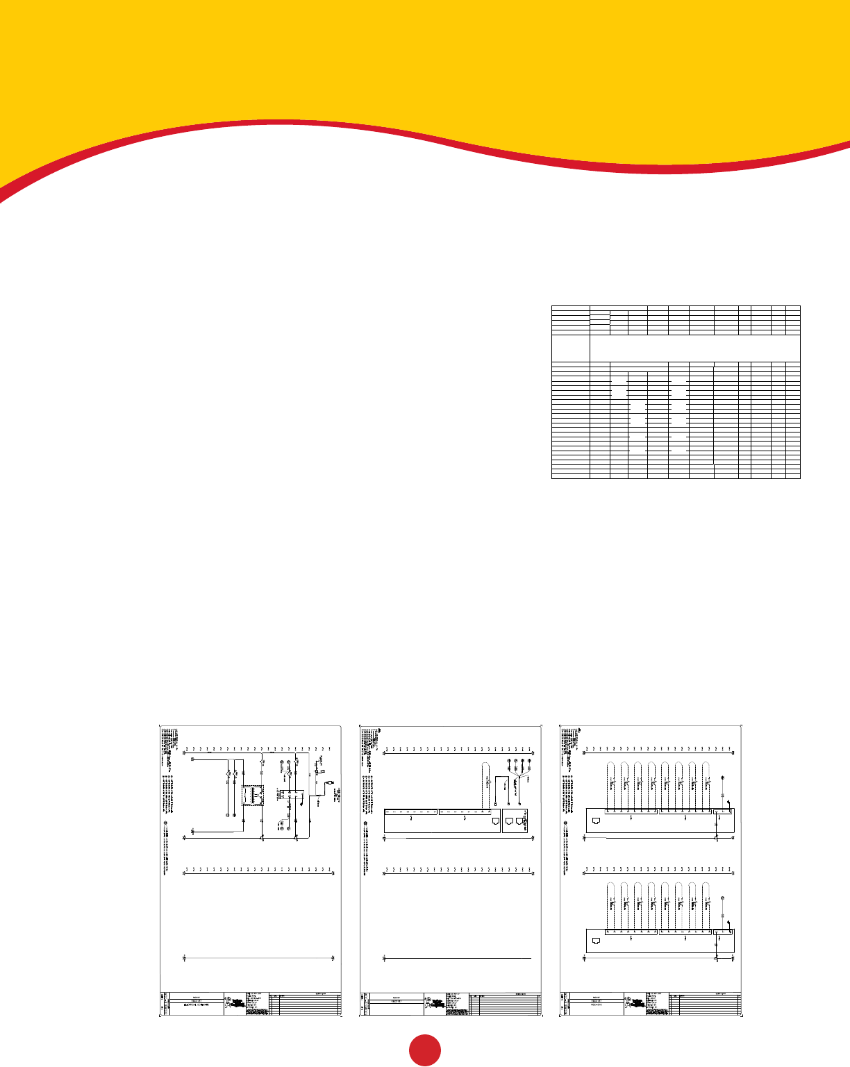
Included Documentation
Unique to each job is a documentation set placed inside
the control panel. This package contains an event table,
electrical diagrams, site plan, and manifold drawing.
Event Table
Before the DSC panel ships it is setup to perform a Play Scenario™
(see page 22) developed by a factory designer. The Play Scenario
consists of one or more events that determine how the water features
will behave. These events are documented on an event table.
The event table assigns the water features to their event numbers,
activators, and the outputs assigned to their solenoid valves.
Secondly, it describes the events’ function which determines how the
water features will behave when they are activated.
Electrical Drawings
These drawings illustrate how the DSC is wired in the panel as well as how to connect the wired activators and
solenoid valves to the terminal blocks.
Note: It is very important to terminate the field wiring (indicated by dashed lines) correctly in order for the
aquatic playground to function in the manner described in the Play Scenario™.
It may be necessary to test the outputs (see page 18) to ensure that the water features’ solenoid valves are
controlled be the outputs shown in the provided electrical drawing.
011
011
011
011
024
021
022
023
031
025
026
027
028
038
034
035
036
037
032
033
021-038
A1
A1
A1
A1
A1
A1
A1
A1
A1
A1
A1
A1
© 2008 FOUNTAIN PEOPLE, INC.
version 1.2
Included Documentation
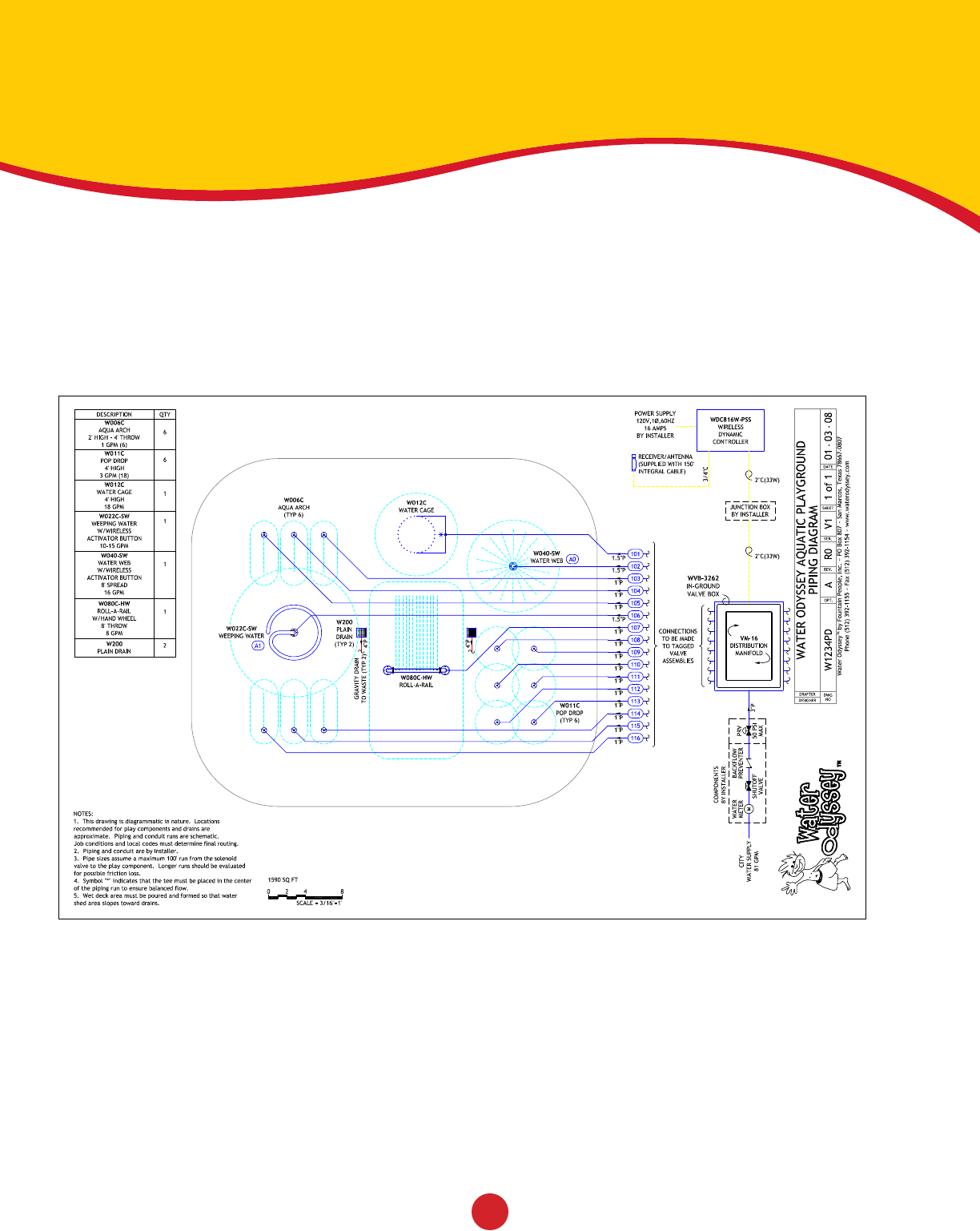
Site Plan Drawing
This drawing shows your aquatic playground layout and illustrates how the play elements and other components
are interrelated. Each discharge line is labeled and corresponds to the electrical drawing. Example, the valve
labeled 102 connects to wired Output 2 on the on module 1.
9

© 2008 FOUNTAIN PEOPLE, INC.
version 1.2 10
Piping & Wiring Verification
Use your Water Odyssey™ Field Connections Drawing to determine how to
plumb each aquatic play element to the appropriate solenoid valve.
Important Note: Your manifold will have tags on the solenoid valves marked to coordinate with the Piping
Diagram and Electrical drawings. The Contractor is required to do the following:
Plumb water features to the appropriate solenoid valves.•
Run independent valve cables from each solenoid to the Water Odyssey Dynamic Sequencing Controller. •
DO NOT SHARE COMMONS. Check label on each wire to assure proper connection.
Connect the solenoid wires to the appropriate terminals according to the electrical drawings.•
Note: If solenoid valves are supplied by others, 24VAC solenoid valves must be used and must not
exceed 18 watts per valve. A pressure regulating valve is necessary to maintain appropriate pressure.
Maximum pressure to the manifold must not exceed 35psi.
As a precaution it is recommended that you verify the water features in your play area are plumbed to
the appropriate solenoid valve. Here are a few items to check:
Cloud 9™ elements should be plumbed to 1” solenoid valves grouped on a manifold with a •
pressure reducing valve set to a maximum of 20 psi.
The larger above ground water features such as a Saguaro Soaker™ should be plumbed to 2” •
solenoid valves grouped with the 1” solenoid valves on a manifold with a maximum of 20 psi.
© 2008 FOUNTAIN PEOPLE, INC.
version 1.2
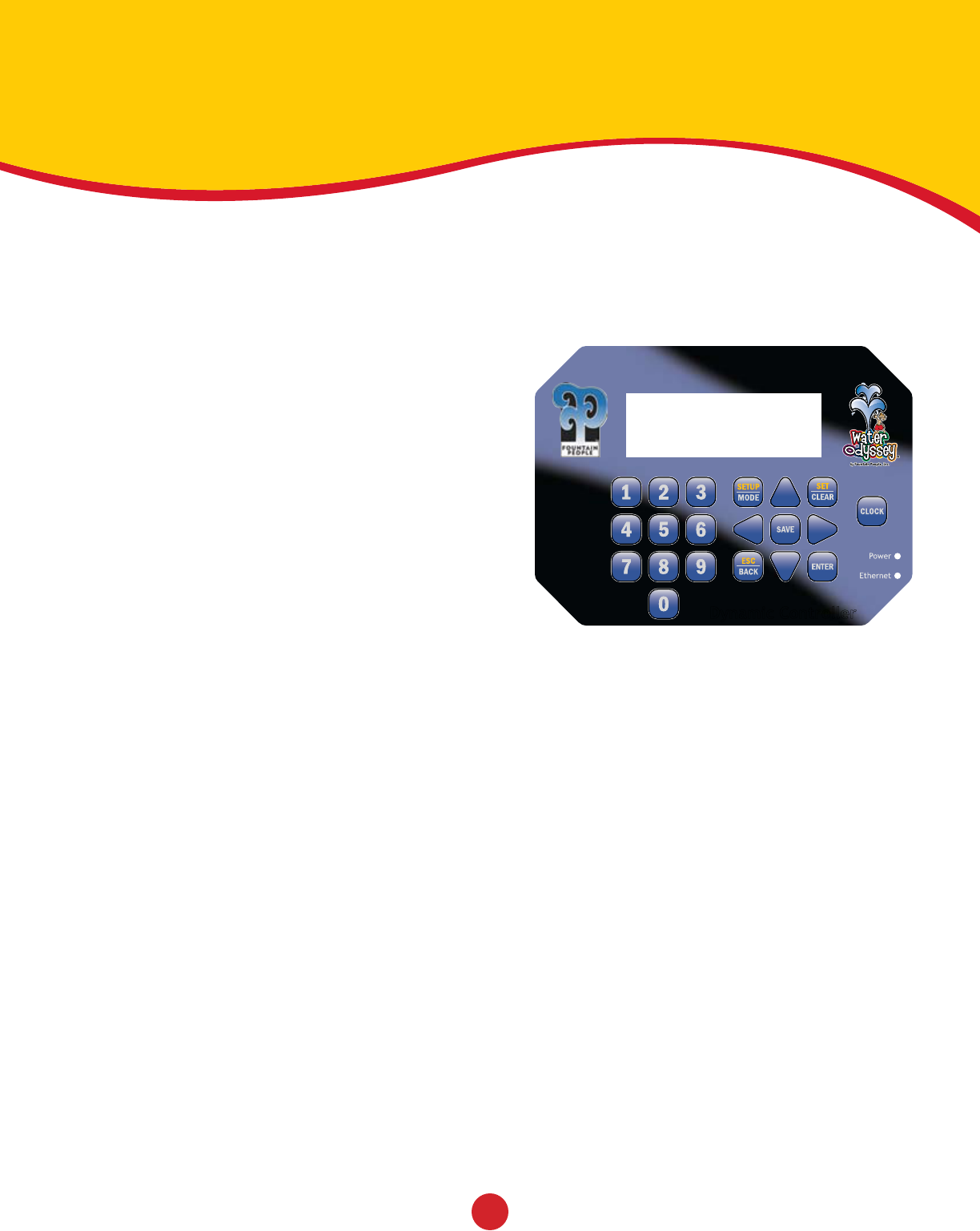
Main Screen & Keypad
Main Screen
This screen is displayed after the DSC has powered up. This screen
displays the Water Odyssey™ project number, the current state of
the operating hours, system messages including when a wireless
activator requires a new battery, and the current date and time.
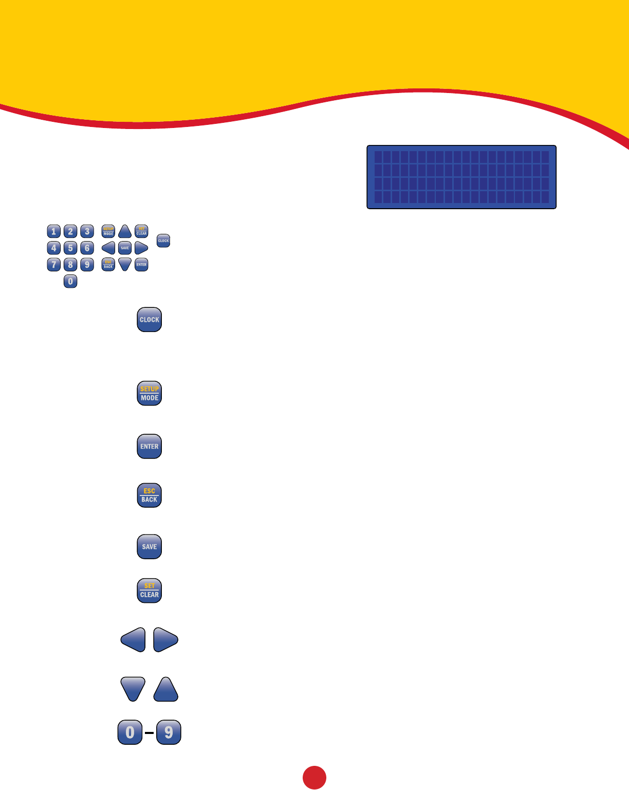
Keypad
The keypad consists of 20 keys used to navigate and modify all the settings in the DSC.
This list describes their most common function.
Clock
Press this key at any time to cycle through operating modes.
•Auto DSCwillrunaccordingtotheoperatinghours.
•On DSCwillforceoperatinghourson.
•Off DSCwillforceoperatinghoursoff.
Setup | Mode
Press this key to access event settings, operating hours, system tests, and system
setup. When a Password is set you are required to enter the password before gaining
access to the controller settings.
Enter
Used for navigation and selection of properties.
ESC | Back
Used for navigation, pressing the [ESC | BACK] key will return you to the previous
screen.
Save
Press this key at anytime to permanently store any changes that you have made.
Set | Clear
Used to modify event properties, operating hours, and defined sequences.
Left and Right Arrows
Used to modify event properties and for navigating operating hours and defined
sequences.
Up and Down Arrows
Used for navigation throughout the menus and settings.
Numbers
Used to enter numeric values and for navigation shortcuts.
W6874 Control System
Push Setup
Operating Hours: On
Thr, Jan 01 11:23 AM
11
© 2008 FOUNTAIN PEOPLE, INC.
version 1.2 12
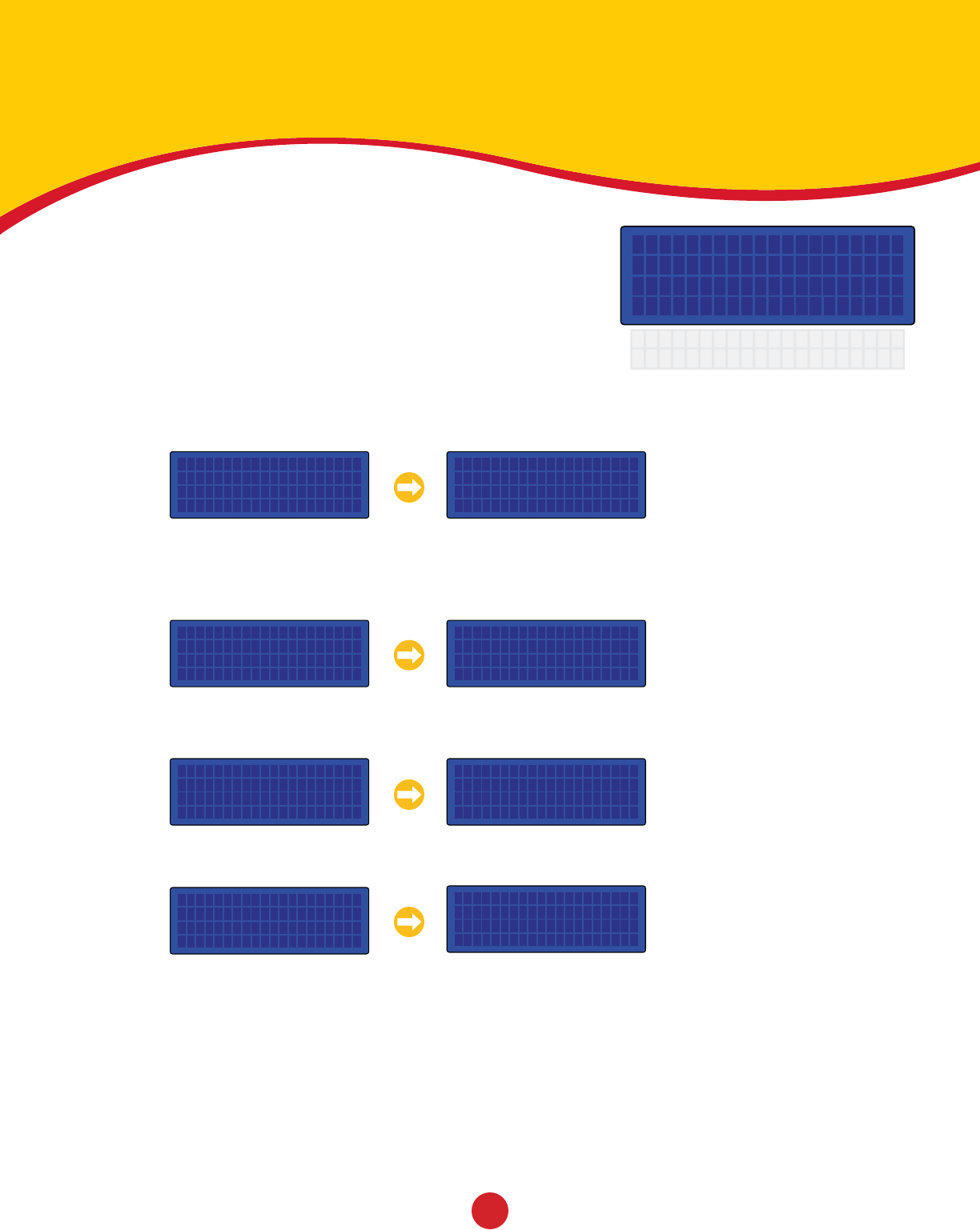
Menu Navigation
The [UP ARROW] and [DOWN ARROW] keys are used to navigate
through menu options. Note that not all menu items are displayed
on the screen at once. This is illustrated by the two options System
Status and System Setup shown below the screen to the left.
To display these options on the screen scroll down using the
[DOWN ARROW] key. The numbers to the left of the menu items are
shortcut keys. These can be used instead of the arrows. For example
pressing the [4] key will go directly to System Setup. Examples in
this manual are shown using shortcut keys whenever possible.
The screen above shows an arrow ( ³ ) pointing to the Events menu item. This arrow indicates the current item
for selection. To select this item press the [ENTER] or [RIGHT ARROW] key. Doing so will display the Events
screen. You can also press the shortcut key, [1].
To access Operating Hours, scroll down using the [DOWN ARROW] key until the arrow points to the Operating
Hours menu item and press the [ENTER] or [RIGHT ARROW] key. You can also press the shortcut key, [2].
To access System Tests, scroll down using the [DOWN ARROW] key until the arrow points to the System Tests
menu item and press the [ENTER] or [RIGHT ARROW] key. You can also press the shortcut key, [3].
To access System Setup, scroll down using the [DOWN ARROW] key until the arrow points to the System Setup
menu item and press the [ENTER] or [RIGHT ARROW] key. You can also press the shortcut key, [4].
Controller Settings
1³Events 00
µ Operating Hours
2 System Status
3 System Setup
Controller Settings
1³Events 00
µ Operating Hours
2 System Status
3 System Setup
Events
1³Add New
µ Edit
Move:15min 10:45 AM
Sun | ¸¶¶¶¶¶·¶¶¶¶¶¶¹
Mon | ¸·¶¶¶¶¶¶¹
Tue | ¸·¶¶¶¶¶¶¹
Controller Settings
´ Operating Hours
1³System Status
µ System Tests
System Status
1³Event 6
µ Module 3
System Setup
1³Set Password
µ Date: 01/01/2008
Controller Settings
´ System Status
4³System Setup
Controller Settings
´ Events 00
1³Operating Hours
µ System Tests
Note: At anytime press the
[ESC | Back] key to return to
the previous screen.
© 2008 FOUNTAIN PEOPLE, INC.
version 1.2
System Setup
´ Date: 01/01/2008
3³Time: 11:23 AM
µ Disable Outputs
Adjust Date & Time
The DSC has a built-in time clock with calendar that will maintain proper time
and date even when the unit is not powered. This gives the DSC the capability
of controlling events based on the time of day and the day of the week.
Adjust the System Time
The DSC is set to your aquatic playground’s time zone
before leaving the factory. The time can be adjusted
using the following procedure.
Starting on the Main Screen, press [SETUP] [4] [3]. This will display the System Settings screen and place
the cursor on the Time item. Next press the [RIGHT ARROW] to place the cursor in the Time field. Using the
numeric keys enter the current time. To change between AM and PM position the cursor on the AM/PM using the
[RIGHT ARROW] key and press the [SET|CLEAR] key.
Example: How to change the time from 11:23 AM to 2:45 PM.
Starting on the Main Screen, press the following keys:
[SETUP] [4] [3] [RIGHT ARROW] [0] [2] [4] [5] [SET|CLEAR] [RIGHT ARROW]
Adjust the System Date
The Date is preset before leaving the factory. The date
can be adjusted using the following procedure.
Starting on the Main Screen, press [SETUP] [4] [2]. This will display the System Settings screen and place the
cursor on the Date item. If you are already on the System Setup screen use the [UP ARROW] and/or [DOWN
ARROW] keys to scroll to the Date item. Next press the [RIGHT ARROW] to place the cursor in the Date field.
Using the numeric keys enter the current date. Note that the DSC will support dates up to the year 2047.
Example: How to change the date from 01/01/2008 to 08/11/2008
Starting on the Main Screen, press the following keys:
[SETUP] [4] [2] [RIGHT ARROW] [8] [1] [1] [0] [8]
System Setup
´ Set Password
2³Date: 01/01/2008
µ Time: 11:23 AM
13
© 2008 FOUNTAIN PEOPLE, INC.
version 1.2 14
Adjust the Operating Hours
Your aquatic playground operating hours can be uniquely set
in 15 minute increments for each day of the week.
The DSC is shipped with operating hours preset to open at 10:00 AM and close at 6:00 PM for your time zone.
These hours can be modified to suit the requirements of the aquatic playground. Each day can have multiple
open and close times and each day of the week can have its’ own unique operating hours.
Access the Operating Hours
Starting on the Main Screen, press [SETUP] [2]. This will display
the Operating Hours screen and place the cursor on Monday at
10:00 AM.
The top row displays the cursor move and the cursor location.
The cursor move determines how many spaces the cursor will move
when the [LEFT ARROW] and [RIGHT ARROW] keys are pressed. The
move value can be adjusted by pressing the [SETUP|MODE] key.
The possible values are 15 minutes and 2 hours.
The cursor location is shown in the upper right corner, 10:45 AM on the screen above. This value will change
when the [LEFT ARROW] or [RIGHT ARROW] key is pressed to reflect the current cursor location.
Use the [UP ARROW] and [DOWN ARROW] keys to scroll through the days of the week. Use the [LEFT ARROW]
and [RIGHT ARROW] keys to scroll through the times of the day. Press the [SET|CLEAR] key to set and clear the
open and close times on the display.
Example: Setting open and close times
Use the [LEFT ARROW] and [RIGHT ARROW] keys to scroll to the time you want the aquatic playground to
open. Press the [SET|CLEAR] key, the screen should be similar to the following. The DSC automatically fills
in the time to the right with dashed lines
Using the [LEFT ARROW] and [RIGHT ARROW] keys scroll to the time you want the aquatic playground to
close. Press the [SET|CLEAR] key, the screen should be similar to the following:
If you insert a time in-between the open and close times all the open and close times to the right will be
inverted. The screen should be similar to the following:
Move:15min 10:45 AM
Sun | ¸¶¶¶¶¶·¶¶¶¶¶¶¶
Mon | ¸·¶¶¶¶¶¶¶
Tue | ¸·¶¶¶¶¶¶¶
Wed | ¸·¶¶¶¶¶¶¶
Thr | ¸·¶¶¶¶¶¶¶
Fri | ¸·¶¶¶¶¶¶¶
Sat | ¸·¶¶¶¶¶¶¶
¸¶¶¶·¶¶¶·¶¶¶·¶¶¶·¶¶¶·¶¶¶·¶¶¶·¶¶¶·¶¶¶·
¸¶¶¶·¶¶¶·¶¶¶·¶¶¶·¶¶¶·¶¶¶·¶¶¶¹
¸¶¶¶·¶¶¶·¶¶¶·¶¶¶·¶¹ ¸¶¶¶·¶¶¶·

© 2008 FOUNTAIN PEOPLE, INC.
version 1.2
Add a Password
To prevent unauthorized personnel from modifying settings, the DSC can
be password protected. Once enabled, a password is required every time
the [SETUP] key is pressed to allow access to the controller’s settings.
The DSC is shipped with password protection enabled. The default
password is 1155. To modify password protection and set a new
system password perform the following steps.
Starting at the Main screen, press [SETUP] enter the password [1]
[1] [5] [5] navigate to the password settings [4] [1]. This will
display the Password screen and wait for you to enter a four digit
password.
Next press the four desired keys to set the password. A password
can only consist of numeric values. After the four keys have been
pressed a second password screen will be displayed requiring that
the four keys are reentered for confirmation.
After the password is reentered you are returned to the System
Setup screen and password protection is now enabled. Once set,
you will be asked to enter the password to gain access to the
DSC’s settings.
Example: How to enable password protection and set the password to 3194.
Starting on the Main Screen, press the following keys:
[SETUP] [1] [1] [5] [5] [4] [1] [3] [1] [9] [4] [3] [1] [9] [4]
To disable password protection go to the set password screen and enter 0000 for the password.
This instructs the DSC to disable password protection.
Example: How to disable password protection.
Starting on the Main Screen, press the following keys:
[SETUP] [Enter Password] [4] [1] [0] [0] [0] [0] [0] [0] [0] [0]
Enter Password
....
Confirm Password
....
15
© 2008 FOUNTAIN PEOPLE, INC.
version 1.2 16
Change the Clock Mode
The operating hours can be overridden simply by pressing the clock override
button. This will allow you to operate the aquatic playground while operating
hours are off, and shut it down while the operating hours are on.
Force Operating Hours On
Press the [CLOCK] key until you see the Operating Hours Forced On
screen. While the DSC display is on the main screen the Forced On
screen will periodically flash as a reminder that the operating hours
are not in their normal automatic mode.
All Events set to run while operating hours are on will be enabled.
Events requiring an activator in order to operate will need to be
activated as they would normally.
Force Operating Hours Off
Press the [CLOCK] key until you see the Operating Hours Forced Off
screen. While the DSC display is on the main screen the Forced Off
screen will periodically flash as a reminder that the operating hours
are not in their normal automatic mode.
All events that require operating hours on in order to operate will be
disabled.
Set Operating Hours to Automatic
Press the [CLOCK] key until you see the Operating Hours Auto
screen. The aquatic playground will start and stop according to the
Operating Hours settings.
Operating Hours
Forced On
Operating Hours
Forced Off
Operating Hours
Auto