Fujitsu 08. FBR 12 Series (p62 65) FBR12
User Manual: Fujitsu FBR12 Series Datasheet - Fujitsu United States
Open the PDF directly: View PDF ![]() .
.
Page Count: 6
(a) Series Name FBR12 : FBR12 Series
(b) Enclosure & Coil Power N : Standard (plastic sealed type)
W : High dielectric strength type (plastic sealed type)
H : High sensitivity type
(c) Coil Type D : DC coil
(d) Nominal Voltage Refer to the COIL DATA CHART
(e) Contact Material Nil : Gold-overlay silver-nickel
–P : Gold-overlay silver-palladium
(f) Custom Designation To be assigned custom specification
(g) CSA Standard –CSA : UL114 + CSA recognized
–CSA : UL1950 + CSA (under application)
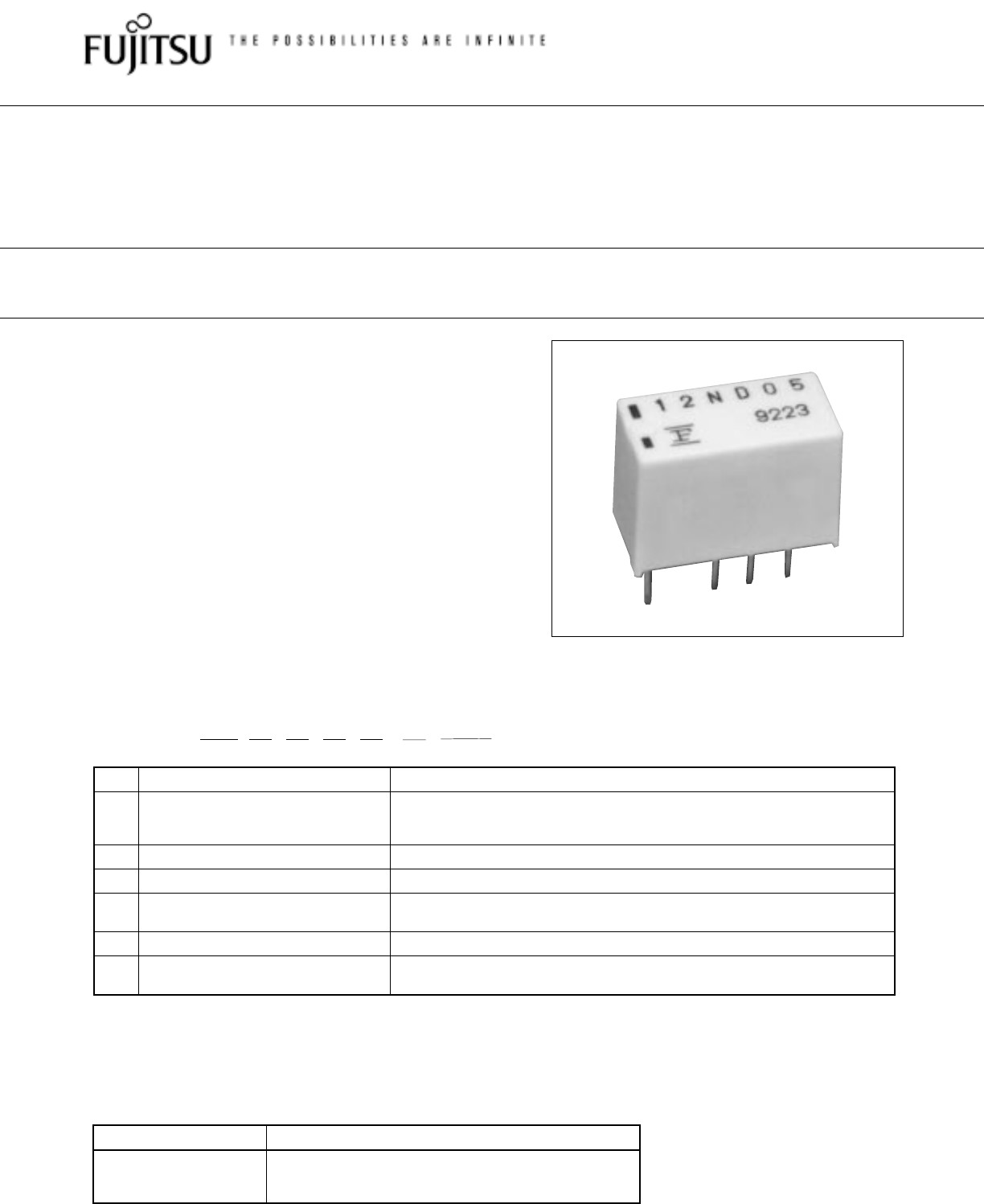
Note: The designation name is stamped on the top of the relay case as follows:
(Example) Designation ordered: FBR12ND05
Stamp: 12ND05
■ FEATURES
●Super miniature size: 0.2 inch × 0.1 inch grid, 12 pin DIP
Up to 50% less volume and board area than previous
generation telecom relay.
●Slim type for high density mounting
●Conforms to Bellcore TR-NWT-001089 and FCC Part 68
requirements
●UL recognized and CSA certified
●Low power consumption
●Conforms to IEC 950 (W type only)
– 2.5 mm clearance and creepage between coil and contacts
–5000 V surge strength between coil and contacts (2x10µs
surge wave)
–2000 Vrms dielectric strength between coil and contacts
–UL 1950 and IEC950 (approval in process)
FBR12 N D 12 –P –** (–CSA)
[Example] (a) (b) (c) (d) (e) (f) (g)
FBR12 SERIES
MINIATURE RELAY
2 POLES—1 to 2 A (FOR SIGNAL SWITCHING)
■ ORDERING INFORMATION
1
■ SAFETY STANDARD AND FILE NUMBERS
Nominal coil voltage Contact rating
0.5 A 125 VDC resistive
3 to 24 VDC 2 A 30 VDC resistive
0.3 A 110 VAC resistive
UL508, 1950, 114 (File No. E63615)
C22.2 No. 0, No. 14 (File No. LR40304 or LR64026)
DISCONTINUED
(2002)
2
FBR12 SERIES
DISCONTINUED
(2002)
Life Mechanical 1 × 10⁸ operations minimum
Electrical DC 2 × 10⁵ operations minimum 5 × 10⁵ operations minimum
(at contact rating)
AC 1 × 10⁵ operations minimum 200 × 103 operations minimum
Other Vibration Misoperation 10 to 55 Hz (double amplitude of 3.3 mm)
Resistance
Endurance 10 to 55 Hz (double amplitude of 5.0 mm)
Shock Misoperation 500 m/s2 (11±1 ms)
Resistance
Endurance 1,000 m/s2 ( 6 ±1 ms)
Weight Approx. 1.5 g Approx. 1.9 g Approx. 1.5 g Approx. 1.9 g
■ SPECIFICATIONS
Item
Standard (Gold-overlay silver-nickel)
-P type (Gold-overlay silver-palladium)
Standard
High dielectric
Standard
High dielectric
strength type strength type
Contact Arrangement 2 form C (DPDT)
Material Gold-overlay silver-nickel Gold-overlay silver-palladium
Style Bifurcated
Resistance (initial) Maximum 100 mΩ (at 0.1 A 6 VDC)
Rating (resistive) 0.5 A 125 VAC or 1 A 30 VDC
Maximum Carrying Current 2 A (at 20°C)
Maximum Switching Power 62.5 VA or 60 W
Max. Switching Voltage*1250 VAC or 220 VDC
Maximum Switching Current 2 A
Minimum Switching Load*210 µA 10 VDC (reference)
Capacitance Approximately 1.0 pF (between open contacts, adjacent contacts )
(at 10 kHz) Approximately1.0 pF (between coil and contacts)
Coil Nominal power (at 20°C) Approximately Approximately Approximately Approximately
0.14 to 0.2 W 0.23 to 0.25 W 0.14 to 0.2 W 0.23 to 0.25 W
Operate power (at 20°C) Approximately Approximately Approximately Approximately
0.08 to 0.112 W 0.13 to 0.14 W 0.08 to 0.112 W 0.13 to 0.14 W
Thermal Resistance at Approximately 115°C/W
Continuous Thermal Load
Operating Temperature –40°C to +85°C (no frost) (refer to the CHARACTERISTIC DATA)
Operating Humidity 45 to 85%RH
Time Value Operate (at nominal voltage) Maximum 4 msec.
Release (at nominal voltage) Maximum 4 msec.
Max. Switching Frequency Mechanical 3 Hz or electrical 0.5 Hz (at contact rating)
Insulation Resistance (initial) Minimum 1000 MΩ (at 500 VDC)
Dielectric
between open contacts
1,000 VAC
Strength
adjacent contacts
1 minimum
between coil and contacts
1,500 VAC 1 min. 2,000 VAC 1 min. 1,500 VAC 1 min. 2,000 VAC 1 min.
Surge
between open
1,500 V
Strength
contacts,
10 × 700 µs
adjacent contacts
between coil and contacts
2,500 V 5,000 V 2,500 V 5,000 V
2 × 10 µs 2 × 10 µs 2 × 10 µs 2 × 10 µs
1,500
750
10 700
2,500
1,250
210
*
1
If the switching voltage exceeds the rated contact voltage, reduce the current. The current values vary according to the
type of load.
*2 Values when switching a resistive load at normal room temperature and humidity and in a clean environment.
The minimum switching load varies with the switching frequency and operation environment.
3
FBR12 SERIES
DISCONTINUED
(2002)
Item
High Sensitive Type
Standard (Gold-overlay silver-nickel)
-P type (Gold-overlay silver-palladium)
Contact Arrangement 2 form C (DPDT)
Material Gold-overlay silver-nickel Gold-overlay silver-palladium
Style Bifurcated
Resistance (initial) Maximum 100 mΩ (at 0.1 A 6 VDC)
Rating (resistive) 0.3 A 125 VAC or 1 A 30 VDC
Maximum Carrying Current 2 A (at 20°C)
Maximum Switching Power 62.5 VA or 30 W
Max. Switching Voltage*1250 VAC or 220 VDC
Maximum Switching Current 2 A
Minimum Switching Load*210m VDC - 10µ A
Capacitance Approximately 1.0 pF (between open contacts, adjacent contacts )
(at 10 kHz) Approximately1.0 pF (between coil and contacts)
Coil Nominal power (at 20°C) Approximately 50mW
Operate power (at 20°C) Approximately 40m W
Operating Temperature –40°C to +70°C (no frost) (refer to the CHARACTERISTIC DATA)
Operating Humidity 45 to 85%RH
Time Value Operate (at nominal voltage) Maximum 5 msec.
Release (at nominal voltage) Maximum 5 msec.
Insulation Resistance (initial) Minimum 1000 MΩ (at 500 VDC)
Dielectric
between open contacts
750 VAC
Strength
adjacent contacts
1 minute
between coil and contacts
1,500 VAC 1 minutes
Surge
between open
1,500 V
Strength
contacts,
10 × 700 µs
adjacent contacts
between coil and contacts
2,500 V
2 × 10 µs
Life Mechanical 1 x 10⁸ operations minimum
Electrical DC 2 × 10⁵ operations minimum 5 × 10⁵ operations minimum
(at contact rating)
AC 1 × 10⁵ operations minimum 200 × 103 operations minimum
Other Vibration Misoperation 10 to 55 Hz (double amplitude of 3.3` mm)
Resistance
Endurance 10 to 55 Hz (double amplitude of 5.0 mm)
Shock Misoperation 500 m/s2 (11±1 ms)
Resistance
Endurance 1,000 m/s2 ( 6 ±1 ms)
Weight Approx. 1.9 g
■ SPECIFICATIONS
*1 If the switching voltage exceeds the rated contact voltage, reduce the current. The current values vary according to the
type of load.
*2 Values when switching a resistive load at normal room temperature and humidity and in a clean environment.
The minimum switching load varies with the switching frequency and operation environment.

4
FBR12 SERIES
DISCONTINUED
(2002)
MODEL
Nominal
Nominal Coil current Must Must
Nominal
Operate
Coil
resistance (at nominal operate operate
temperature
voltage (
±
10%) voltage) voltage*1voltage*1
power
power
rise
Standard -P type
approx.
FBR12ND03 FBR12ND03-P 3 VDC 64.3 Ω46 mA
FBR12ND04 FBR12ND04-P 4.5 VDC 145 Ω31 mA
FBR12ND05 FBR12ND05-P 5 VDC 178 Ω28 mA 75% max. 10% min.
Approx. Approx. Approx.
of nominal of nominal
0.14 W 0.08 W 20 deg
FBR12ND06 FBR12ND06-P 6 VDC 257 Ω23 mA
(at nominal Max.
voltage voltage
voltage) Max. (at nominal
FBR12ND09 FBR12ND09-P 9 VDC 579 Ω15 mA
voltage)
FBR12ND12 FBR12ND12-P 12 VDC 1,028 Ω11 mA
FBR12ND24 FBR12ND24-P 24 VDC 2,880 Ω 8 mA 0.2 W 0.112 W 30 deg
■ COIL DATA CHART
*1: Specified values are subject to pulse wave voltage.
Note: All values in the table are measured at 20°C.
MODEL
Nominal
Nominal Coil current Must Must
Nominal
Operate
Coil
resistance (at nominal operate release
temperature
voltage (
±
10%) voltage) voltage*1voltage*1
power
power
rise
Standard -P type
approx.
FBR12WD03 FBR12WD03-P 3 VDC 39 Ω77 mA
FBR12WD04 FBR12WD04-P 4.5 VDC 88 Ω51 mA
FBR12WD05 FBR12WD05-P 5 VDC 108 Ω46 mA 75% max. 10% min.
Approx. Approx. Approx.
of nominal of nominal
0.23 W 0.13 W 30 deg
FBR12WD06 FBR12WD06-P 6 VDC 156 Ω38 mA
(at nominal (at nominal
voltage voltage
voltage) Max. voltage)
FBR12WD09 FBR12WD09-P 9 VDC 352 Ω25 mA
FBR12WD12 FBR12WD12-P 12 VDC 626 Ω19 mA
FBR12WD24 FBR12WD24-P 24 VDC 2,304 Ω10 mA 0.25 W 0.14 W 33 deg
*1: Specified values are subject to pulse wave voltage.
Note: All values in the table are measured at 20°C.
1.STANDARD
2.HIGH DIELECTRIC STRENGTH
MODEL
Nominal Coil Must Must
Nominal
Operate
Coil
resistance operate release
temperature
voltage (
±
10%) voltage*1voltage*1
power
power
rise
Standard -P type
FBR12HD03 FBR12HD03-P 3 VDC 180 Ω
FBR12HD04 FBR12HD04-P 4.5 VDC 405 Ω
FBR12HD05 FBR12HD05-P 5 VDC 500 Ω 80% max. 10% min.
Approx. Approx. Approx.
of nominal of nominal
0.05 W 0.04 W 4 deg
FBR12HD06 FBR12HD06-P 6 VDC 720 Ω
(at nominal (at nominal
voltage voltage
voltage) Max. voltage)
FBR12HD09 FBR12HD09-P 9 VDC 1,620 Ω
FBR12HD12 FBR12HD12-P 12 VDC 2,880 Ω
*1: Specified values are subject to pulse wave voltage.
Note: All values in the table are measured at 20°C.
3. HIGH SENSITIVITY TYPE
5
FBR12 SERIES
DISCONTINUED
(2002)
■ DIMENSIONS
Unit: mm
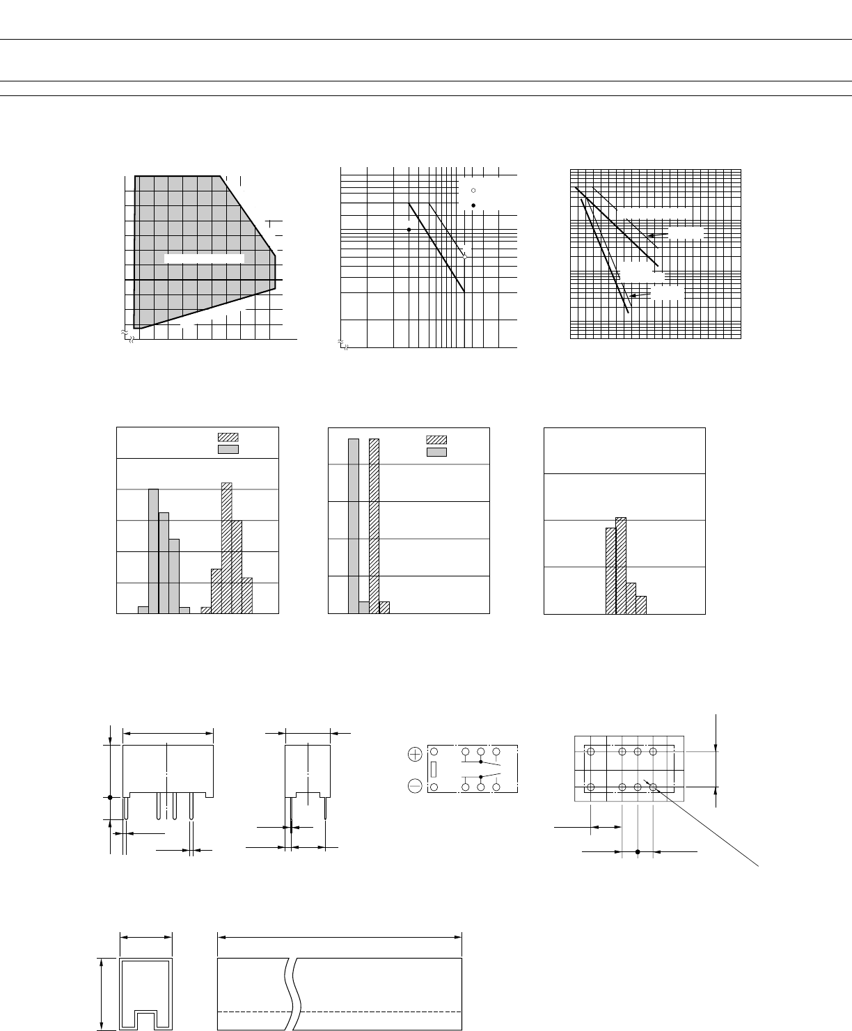
■ REFERENCE DATA
■ CHARACTERISTIC DATA
Life curve
500
Contact load current (A)
50
5
10
1
100
(×10
4
)
Service life (operations)
0.5 1.0 1.5 2.0
Maximum switching capacity
Contact load voltage (V)
0.1
10 20 125 200
30 50
0.2
0.3
0.5
1.0
2.0
➀
Range of operation temperature and voltage
Operating temperature (˚C)
–100 1020304050607080
70
80
90
100
110
120
130
140
150
160
➀ AC resistive load
( AC contact rating)
➁ DC resistive load
( DC contact rating)
Operating voltage range
Must operate voltage
Maximum allowable coil voltage
(DATA) assumes that
the maximum allow-
able temperature of
E type insulation
coil is 115˚C
➁
Contact load current (A)
Nominal voltage multiplying factor (%)
125 V AC
resistive load
30 V DC resistive load
(–P)TYPE
(–P)TYPE
●Dimensions ●Schematics
(BOTTOM VIEW)
●PC board mounting hole layout
(BOTTOM VIEW)
●Tube carrier
14.6
+0.4
0.50
(0.95)
9.7
+0.3
3.2
7.2
+0.3
0.25
(1.06) 5.08
1
12
3
10
4
9
5
8
5.08
2.54
5.08
2.54
8–ø1.00
10.6 Max.
30 pcs/Tube
15.6 Max.
500
±2
✽SHOW ONE OUT
OF THBSB 3 DIMENSIONS (See NA)
Operate
Release
Distribution of operate and release voltage
Rated coil voltage multiplying factor (%)
60
50
40
20
30
10
01020 304050 607080
0
Distribution (%)
Operate
Release
Distribution of operate and release time
Time (ms)
100
80
60
20
40
012 345678
0
Contact resistance (mΩ)
Distribution of contact resistance
80
60
40
20
01020 304050 607080
0
Distribution (%)
Distribution (%)

6
FBR12 SERIES
DISCONTINUED
(2002)
© 2001 Fujitsu Components America, Inc. All company and product names are trademarks or registered trademarks
of their respective owners. Rev. 09/2001
Japan
Fujitsu Component Limited
Gotanda-Chuo Building
3-5, Higashigotanda 2-chome, Shinagawa-ku
Tokyo 141, Japan
Tel: (81-3) 5449-7010
Fax: (81-3) 5449-2626
Email: promothq@ft.ed.fujitsu.com
Web: www.fcl.fujitsu.com
North and South America
Fujitsu Components America, Inc.
250 E. Caribbean Drive
Sunnyvale, CA 94089 U.S.A.
Tel: (1-408) 745-4900
Fax: (1-408) 745-4970
Email: marcom@fcai.fujitsu.com
Web: www.fcai.fujitsu.com
Europe
Fujitsu Components Europe B.V.
Diamantlaan 25
2132 WV Hoofddorp
Netherlands
Tel: (31-23) 5560910
Fax: (31-23) 5560950
Email: info.marketing@fceu.fujitsu.com
Web: www.fceu.fujitsu.com
Asia Pacific
Fujitsu Components Asia Ltd.
102E Pasir Panjang Road
#04-01 Citilink Warehouse Complex
Singapore 118529
Tel: (65) 375-8560
Fax: (65) 273-3021
Email: fcal@fcal.fujitsu.com
www.fcal.fujitsu.com
Fujitsu Components
International
Headquarter
Offices
