Funk Electronic Piciorgros TMO-100 800 MHZ TETRA RADIO User Manual TMO 100 2017
Funk-Electronic Piciorgros GmbH 800 MHZ TETRA RADIO TMO 100 2017
UserManual.wiki
>
Funk Electronic Piciorgros
>
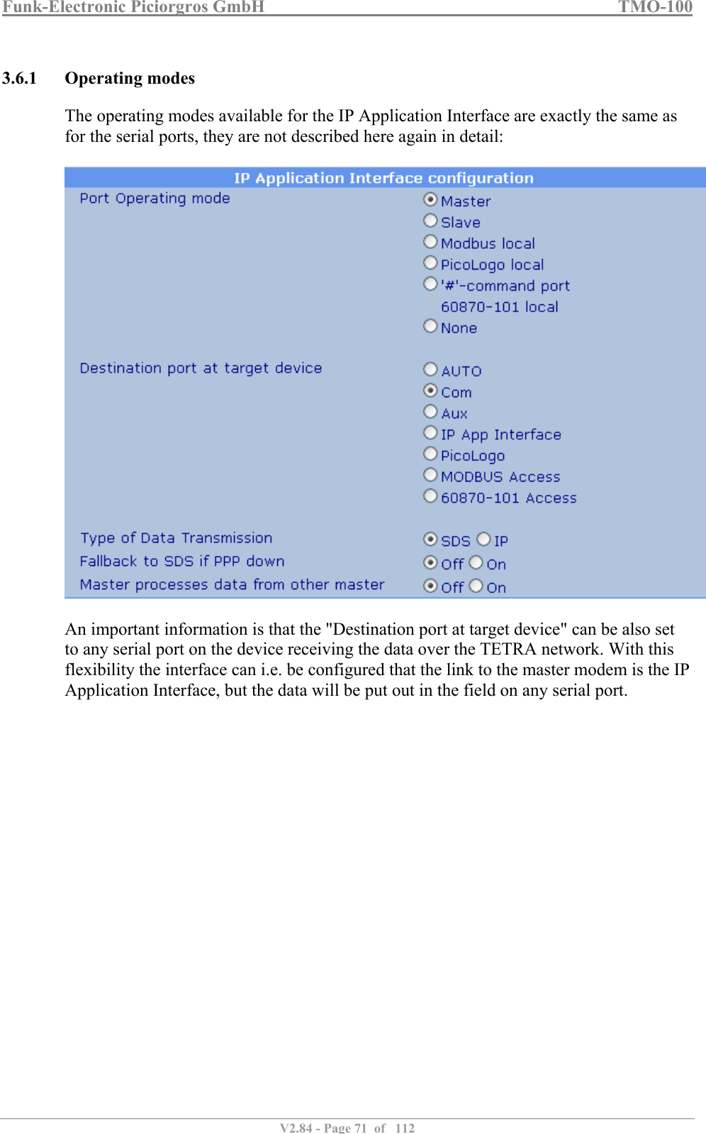
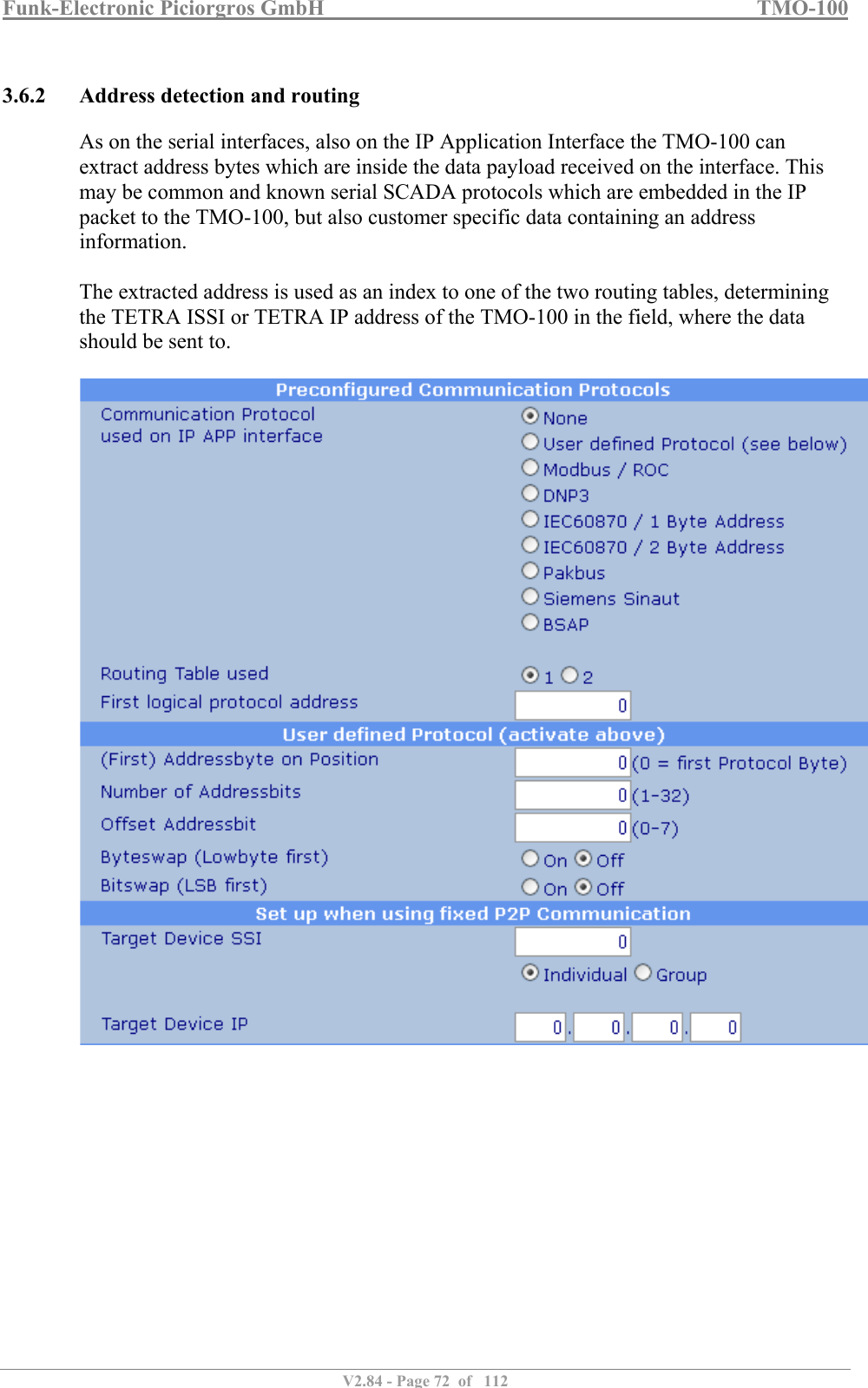
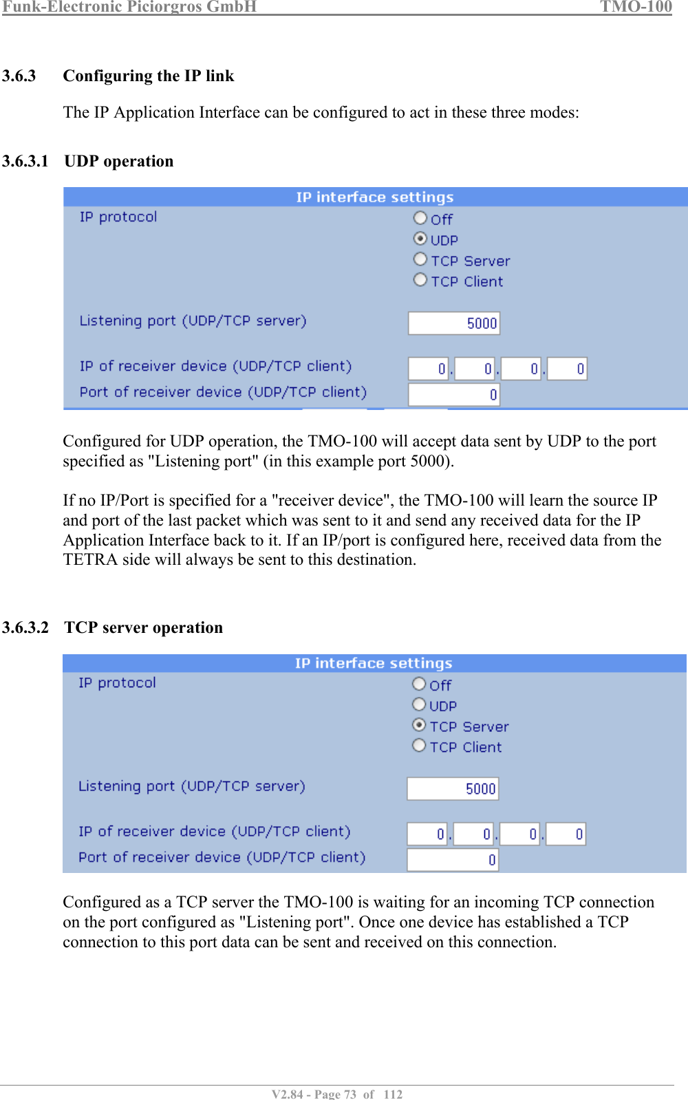
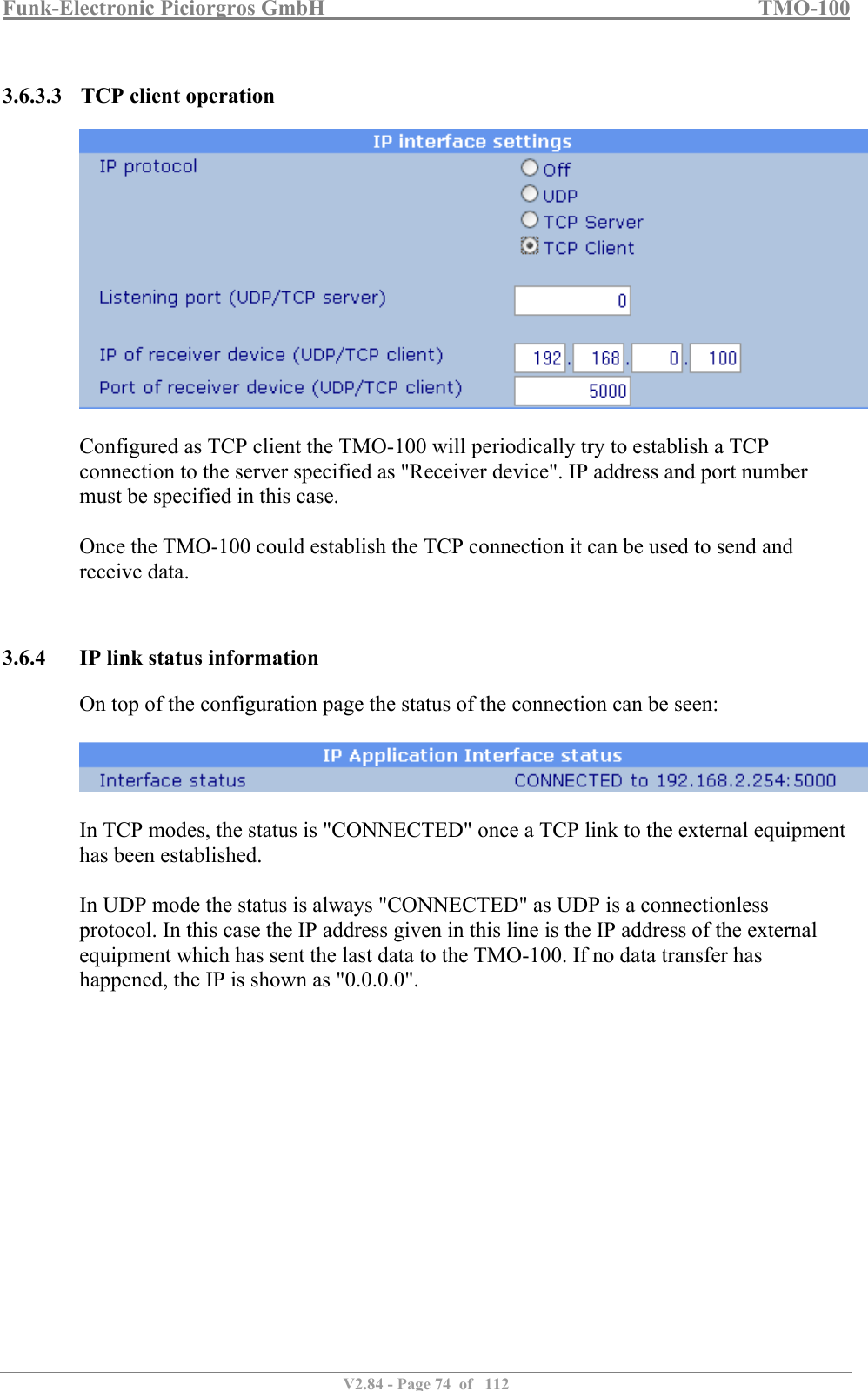
TMO-100 User Manual
>
User Manual
Contents
1.
Instruction Leaflet TMO-100_engl
2.
TMO-100_E_V1.821.pdf
3.
User manual
4.
User guide
5.
User manual update
6.
User Manual
User Manual
Navigation menu
Upload a User Manual
Namespaces
Wiki Guide
HTML
PDF
Info
Views
User Manual
Discussion / Help
Navigation

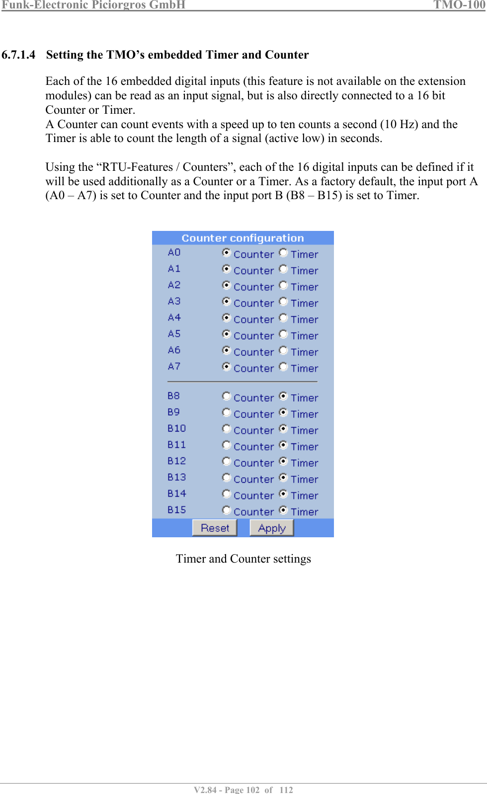
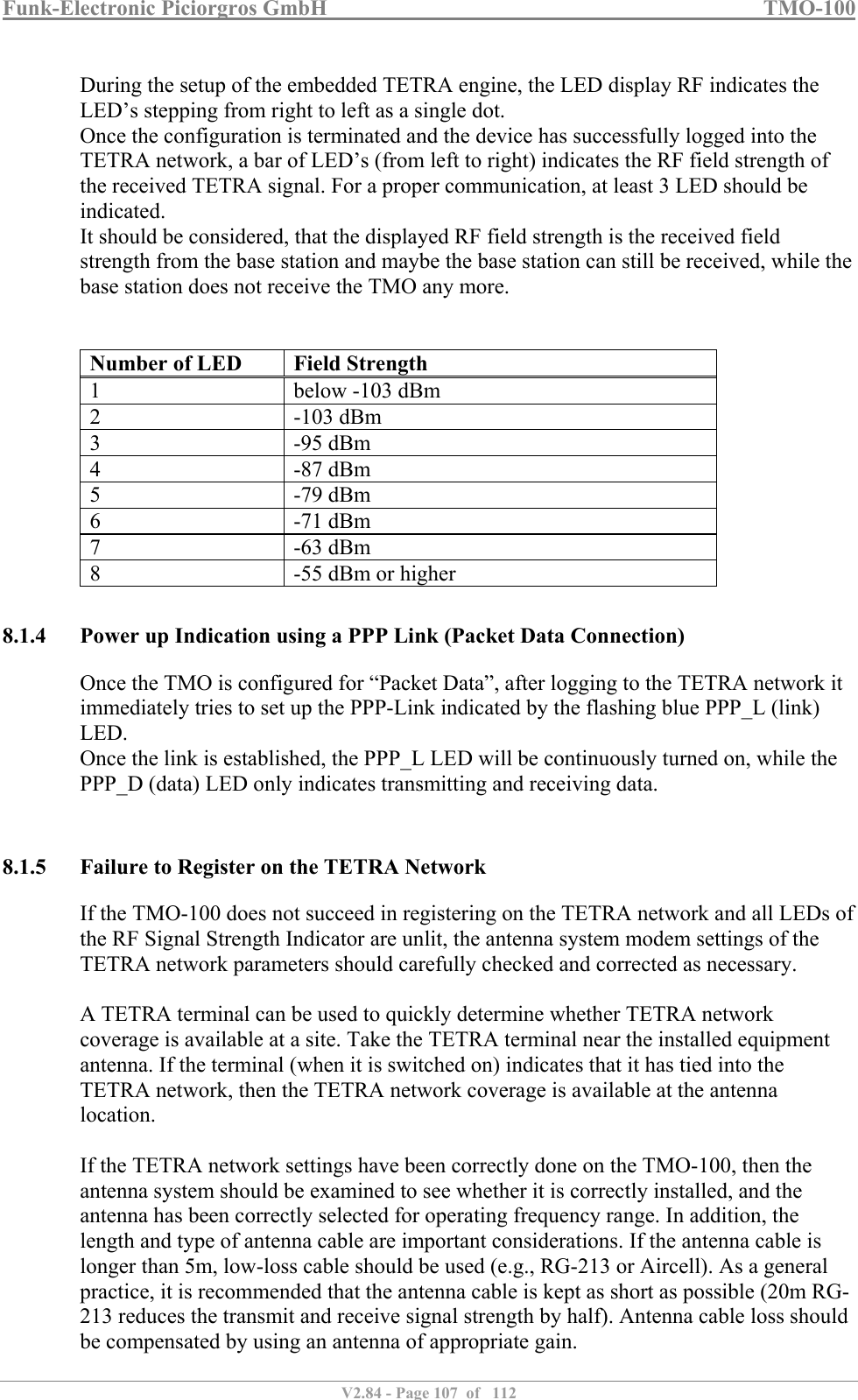
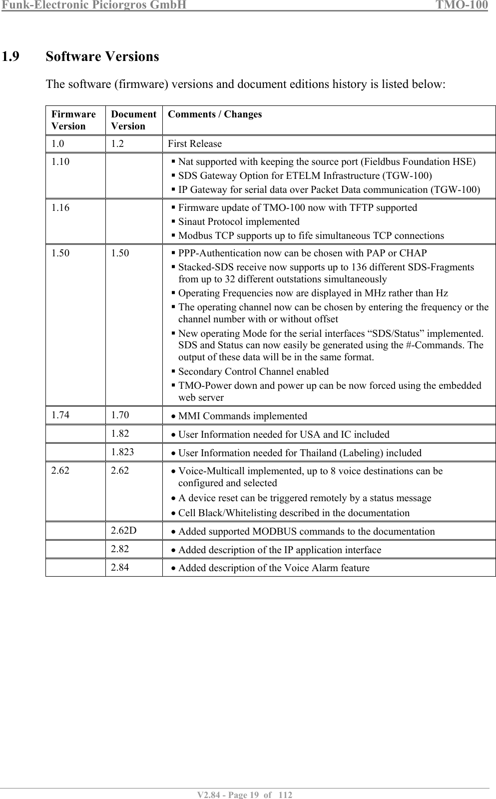
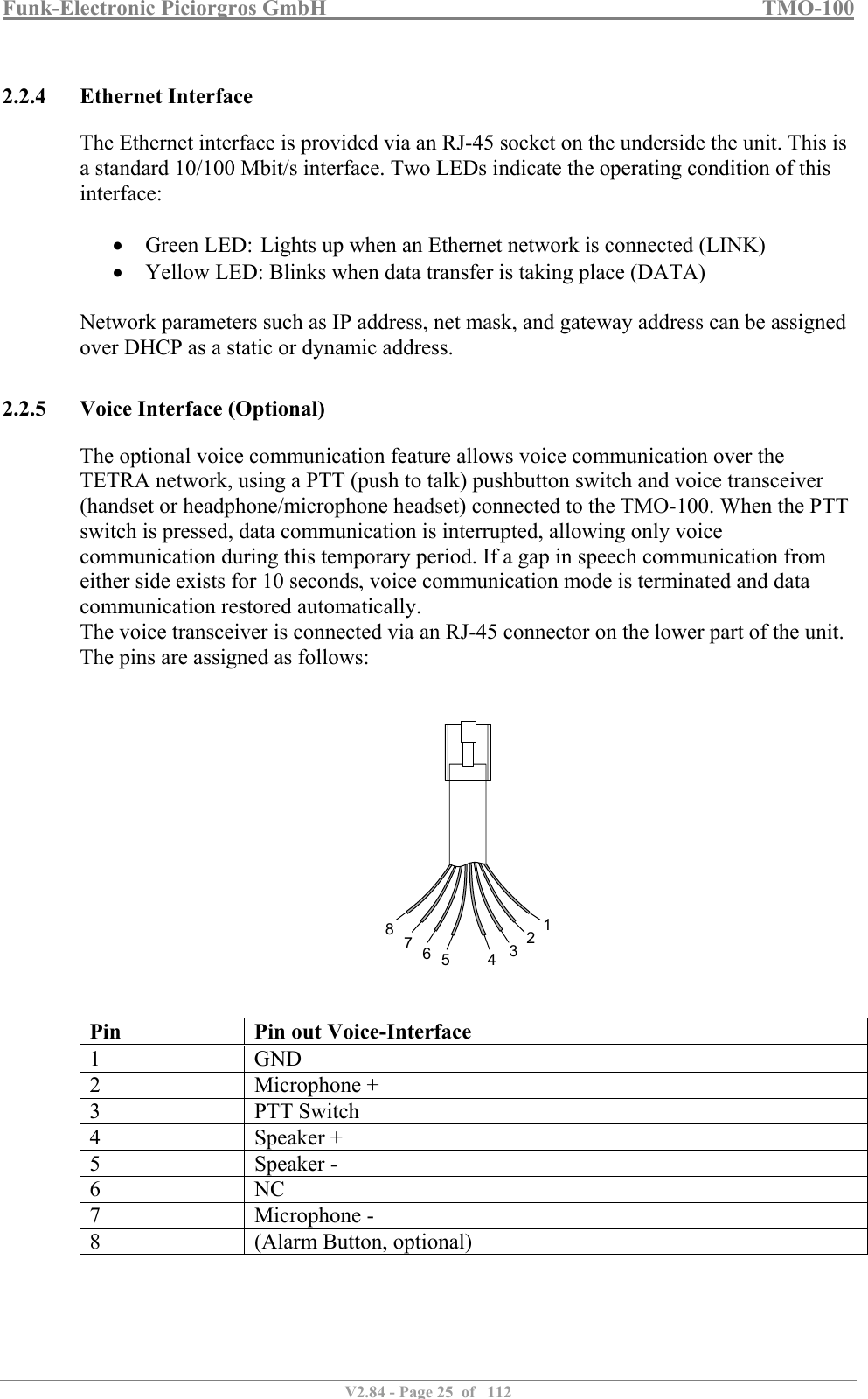
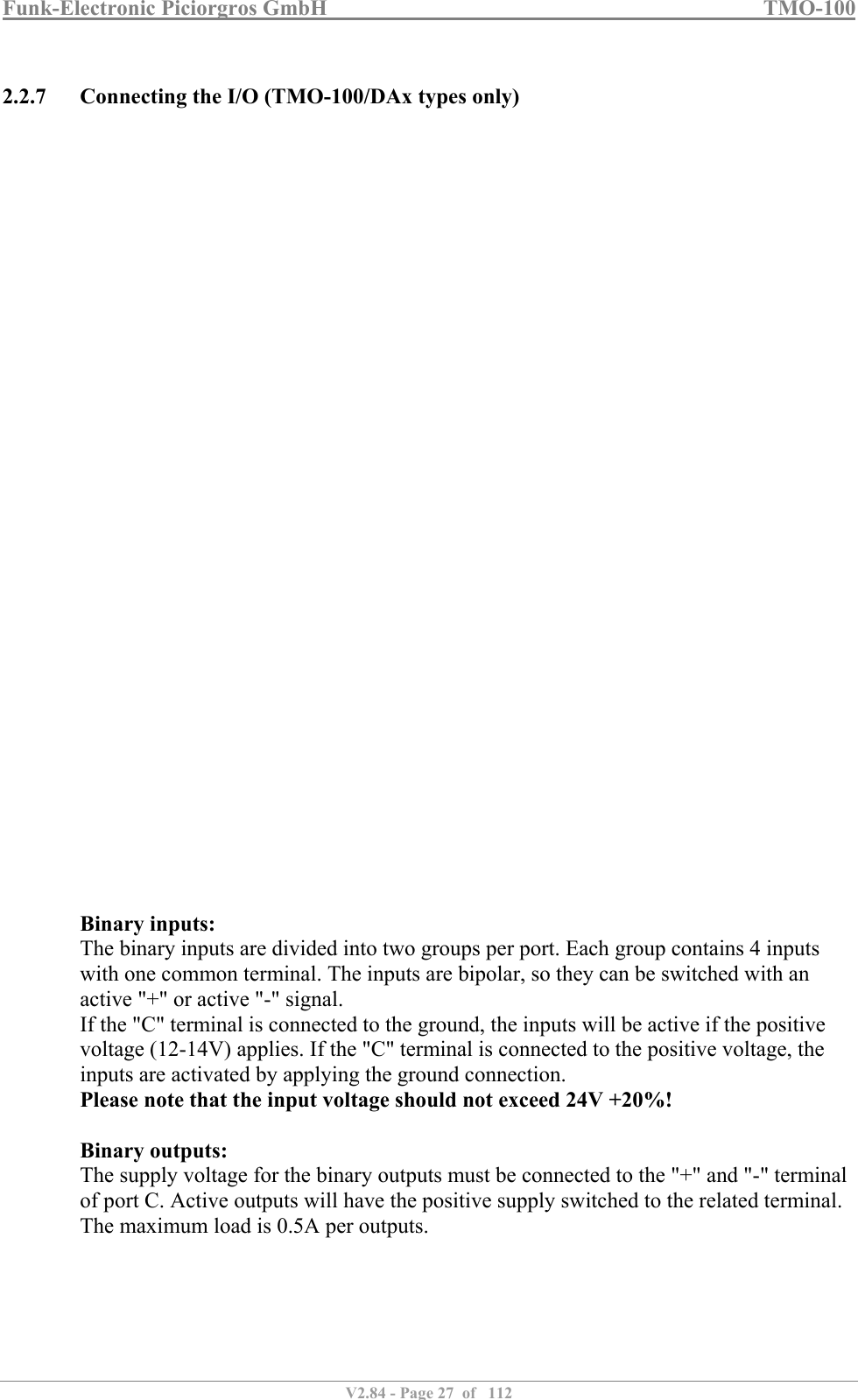
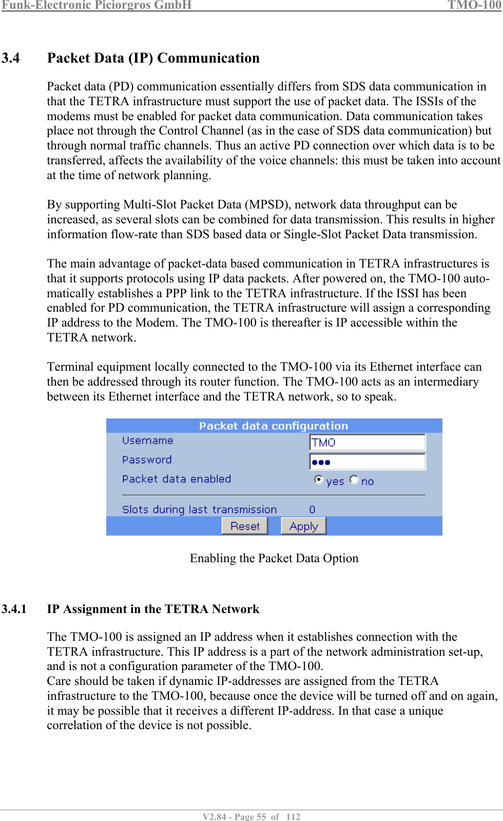
![Funk-Electronic Piciorgros GmbH TMO-100 V2.84 - Page 9 of 112 Interference with other equipment or services This equipment has been tested and found to comply with the limits for a Class B digital device, pursuant to part 15 of the FCC Rules. These limits are designed to provide reasonable protection against harmful interference in a residential installation. This equipment generates uses and can radiate radio frequency energy and, if not installed and used in accordance with the instructions, may cause harmful interference to radio communications. However, there is no guarantee that interference will not occur in a particular installation. If this equipment does cause harmful interference to radio or television reception, which can be determined by turning the equipment off and on, the user is encouraged to try to correct the interference by one or more of the following measures: Reorient or relocate the receiving antenna. Increase the separation between the equipment and receiver. Connect the equipment into an outlet on a circuit different from that to which the receiver is connected. Consult the dealer or an experienced radio/ TV technician for help. 1.4.7 FCC RF exposure compliance To comply with the FCC RF exposure compliance the antenna used for the TMO-100 must be installed to provide a minimum separation distance to any person as shown below: Radio Tx Power [W] 1.8 1.8 1.8 1.8 1.8 Antenna Gain [dBi] 0 3 7 10 13 Antenna Output Power [EIRP] 1.8 W 3.6 W 9 W 18 W 36 W Minimum Separation Distance [m] 1 m 1.4 m 2.1 m 3 m 4.2 m 1.4.8 FCC Part 15.19 Warning Statement THIS DEVICE COMPLIES WITH PART 15 OF THE FCC RULES. OPERATION IS SUBJECT TO THE FOLLOWING TWO CONDITIONS: (1) THIS DEVICE MAY NOT CAUSE HARMFUL INTERFERENCE, AND (2) THIS DEVICE MUST ACCEPT ANY INTERFERENCE RECEIVED, INCLUDING INTERFERENCE THAT MAY CAUSE UNDESIRED OPERATION. 1.4.9 FCC Part 15.21 Warning Statement NOTE: THE GRANTEE IS NOT RESPONSIBLE FOR ANY CHANGES OR MODIFICATIONS NOT EXPRESSLY APPROVED BY THE PARTY RESPONSIBLE FOR COMPLIANCE. SUCH MODIFICATIONS COULD VOID THE USER’S AUTHORITY TO OPERATE THE EQUIPMENT.](https://usermanual.wiki/Funk-Electronic-Piciorgros/TMO-100.User-Manual/User-Guide-3291480-Page-9.png)
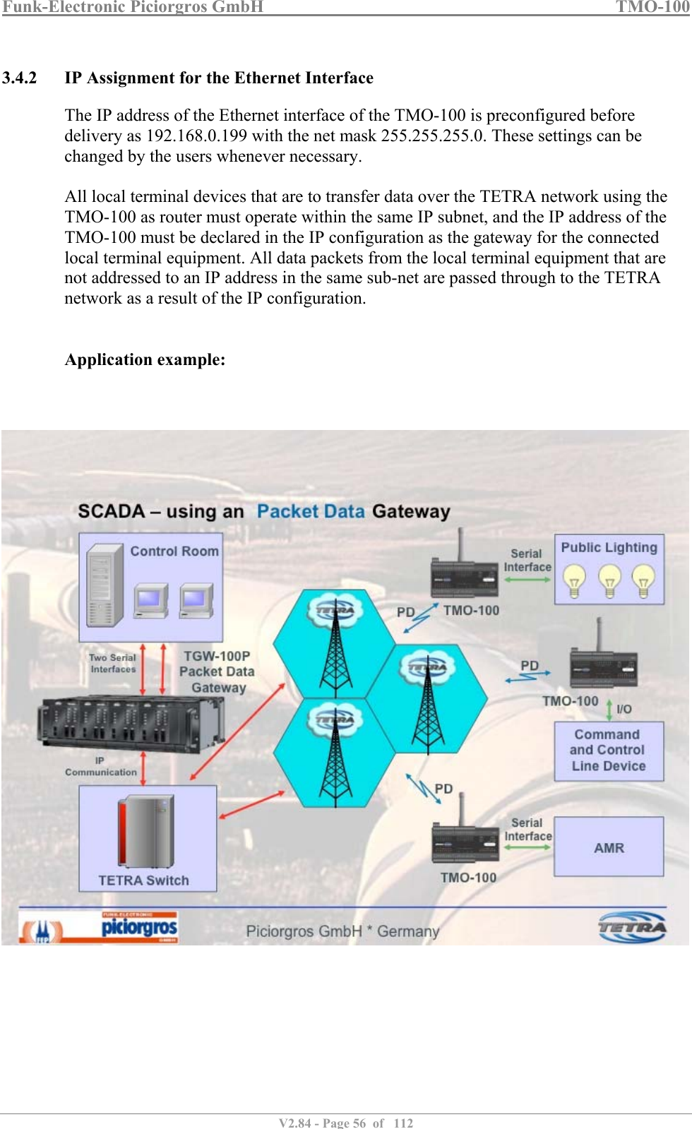
![Funk-Electronic Piciorgros GmbH TMO-100 V2.84 - Page 14 of 112 1.6 Functions and Features The TMO-100 is a radio data communication modem for TETRA networks. These modems allow transparent data communication between two or more nodes in a TETRA network. The TMO-100 conveniently combines the functions of a controller, router, modem, and radio transceiver in a single compact enclosure. The TMO-100 supports standard serial and IP-based data communication protocols. It has two serial data interfaces (RS-232 or RS-485/422) and an Ethernet (10/100 Mbits/sec) port. For TETRA radio networking, either of two modes can be selected: SDS based communication or packet data transmission. An optional voice communication feature is also available, by which field personnel can talk with a control room. The TMO-100 can also be optionally provided with built-in inputs and outputs that can be read and set remotely using the MODBUS-RTU protocol. It is possible to transmit information about an input change automatically to another station as soon as an alarm condition occurs ["unsolicited message"]. The TMO-100 has a rugged aluminum housing compatible with standard DIN rail mounting. The wide power input voltage range of 12-24 VDC [+/- 20%] makes it easy to integrate the unit into monitoring and control systems.](https://usermanual.wiki/Funk-Electronic-Piciorgros/TMO-100.User-Manual/User-Guide-3291480-Page-14.png)
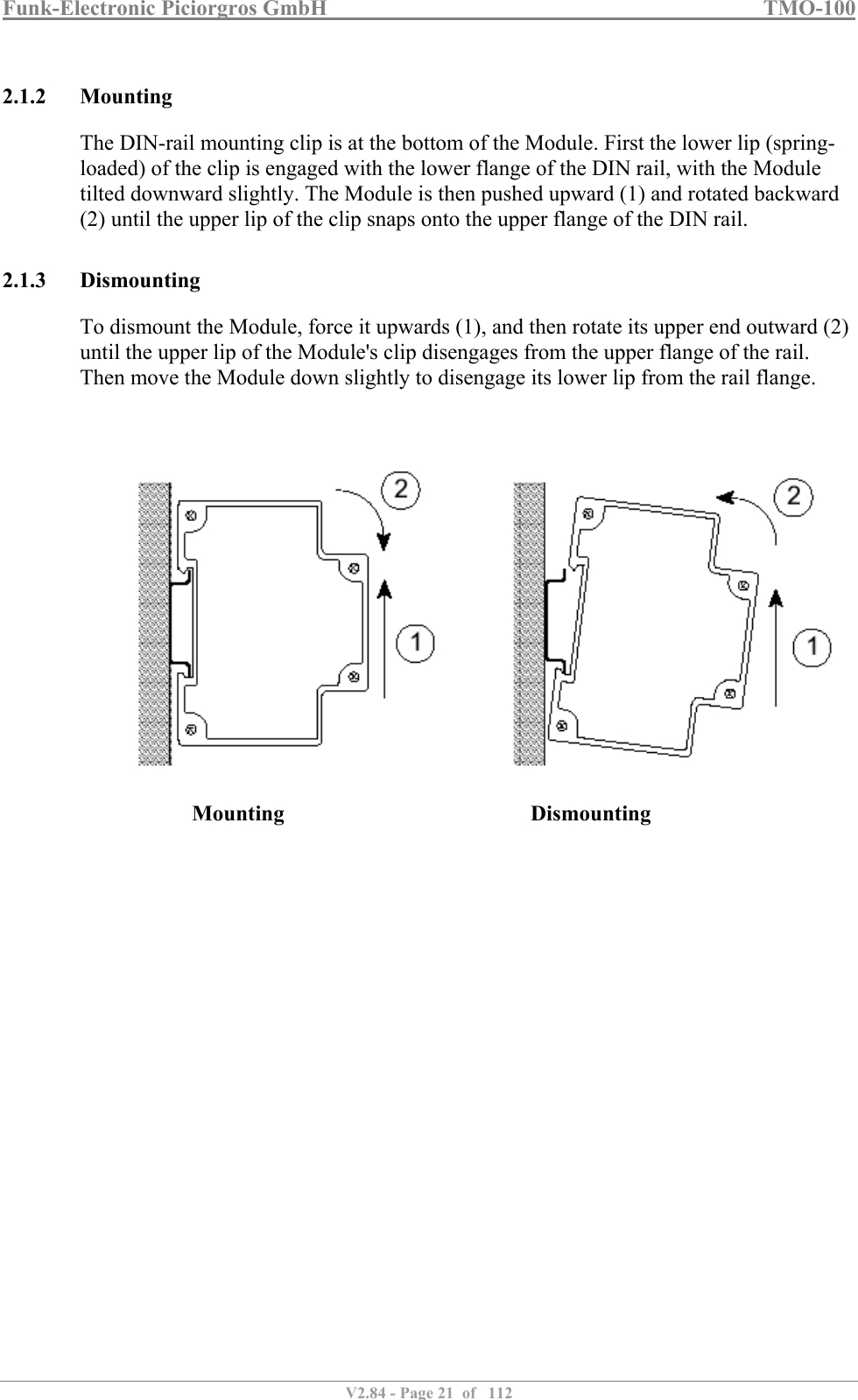
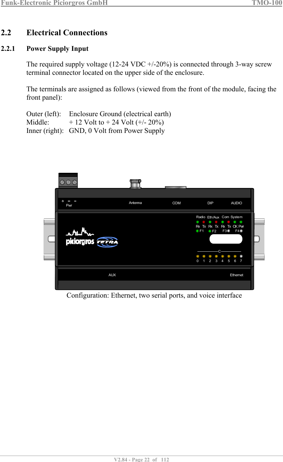
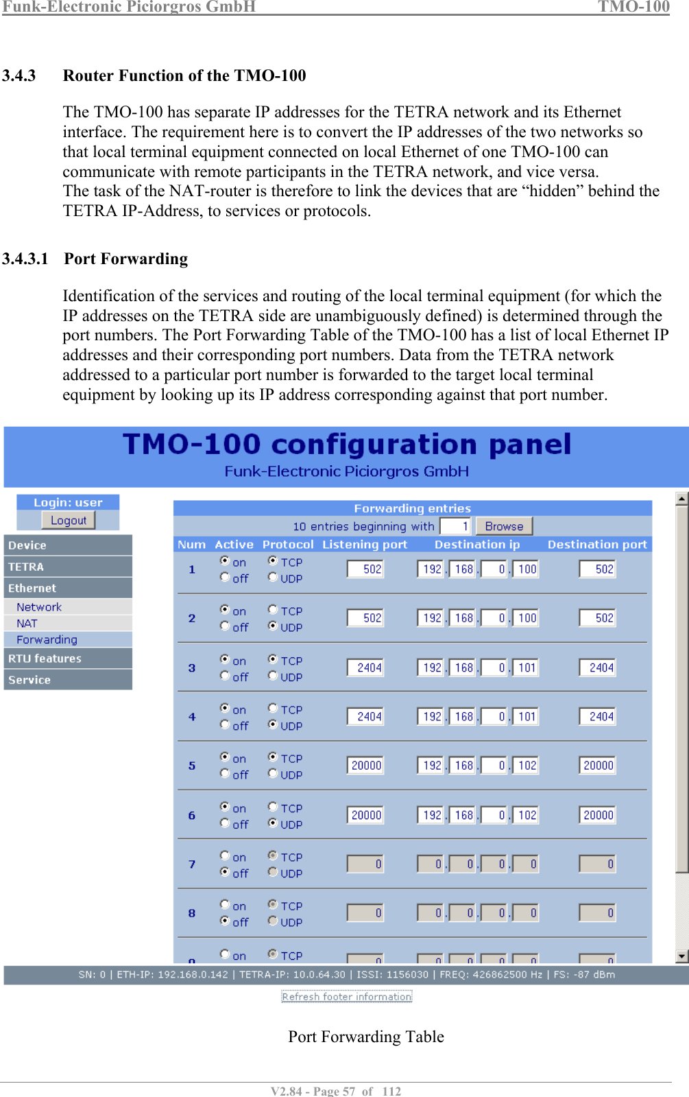
![Funk-Electronic Piciorgros GmbH TMO-100 V2.84 - Page 20 of 112 2 Connections and Hardware Installation 2.1 Mechanical Details The dimensions of the TMO-100 housing conform to DIN 43880, and therefore it can be mounted on a standard 35mm DIN rail [DIN EN 50022]. Two serial interfaces are provided for connecting the TMO-100 to a PC/PLC or other local terminal equipment. The main serial interface ("COM") uses a standard 9-pin D-sub connector, while the secondary serial interface ("AUX") uses a standard RJ-11 socket. On the lower side of the housing an RJ-45 connector for the Ethernet port allows the TMO-100 to be hard-wire networked with local terminal equipment or PLC’s. On the upper side of unit another RJ-45 connector is provided for connecting a voice handset, for speech communication over the TETRA network. On the upper side of the unit is located the plug-in terminal connector for the power supply (12-24 VDC +/-20%) and a BNC socket for the antenna. A 10-pole DIP-switch allows quick changes to the unit's settings: e.g., changeover to Programming Mode. LED lamps on the front panel provide information about the operating condition of the unit: e.g., received TETRA RF signal strength, error conditions, etc. 2.1.1 Dimensions The dimensions of the TMO-100 are as follows: 162mm (9T) wide x 80mm high x 62mm deep All dimensions exclude connectors and antenna. RFBDAC080123001911210223113341244513556146671577CCOut CC+++++-----012301234567CC0819210311412513614In InIn In715CC80 mm60 mm162 mmRadioRx Rx RxTx Tx Tx OK PwrEth/Aux SystemComF1 F2 F4F3](https://usermanual.wiki/Funk-Electronic-Piciorgros/TMO-100.User-Manual/User-Guide-3291480-Page-20.png)
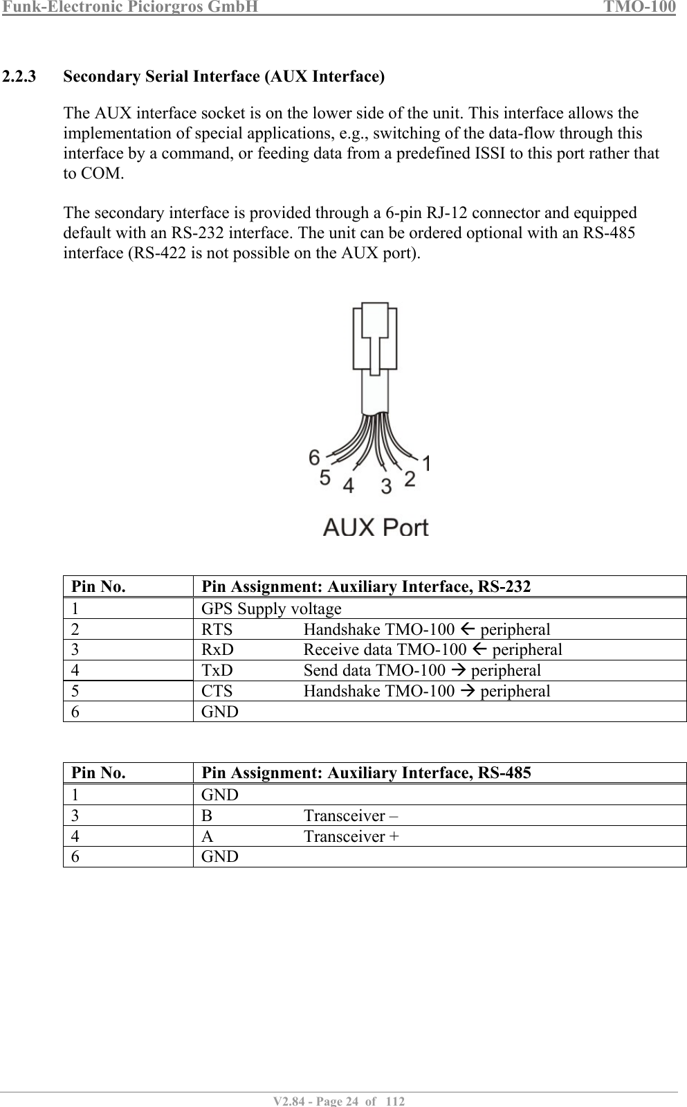
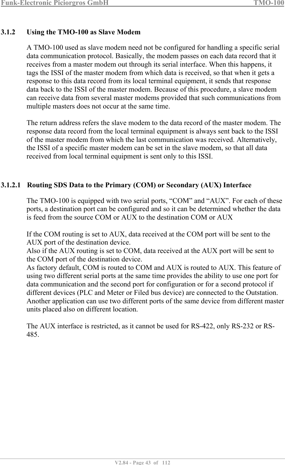
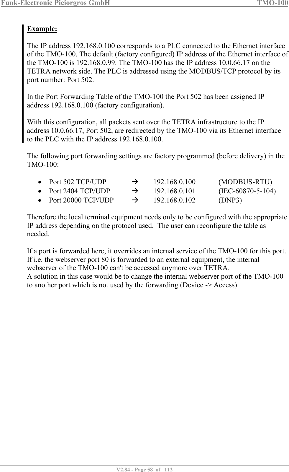
![Funk-Electronic Piciorgros GmbH TMO-100 V2.84 - Page 23 of 112 2.2.2 Serial Interfaces The TMO-100 has two serial data interfaces. The primary interface (COM) has a 9-pin D-sub connector on the upper side of the unit. The secondary interface [AUX] has an RJ-11 socket on the lower side of the unit. The COM interface can be either RS-232 or user-selectable RS-422/485. The AUX interface can be RS-232 or RS-485 (only). The following parameters are user adjustable: baud rate in the range 1200 - 57600 bps, data word length 7 or 8 bits, odd / even / no parity, and 1 or 2 stop bits. The factory setting is 9600 bps, 8 data bits, no parity, 1 stop bit. If a frame error is detected, or if the parity bit does not conform to the setting, the received data block is rejected. Both serial interfaces are supplied as RS-232, unless ordered otherwise. The primary interface is optionally available as a user-selectable RS-485 / RS-422 port, while the AUX interface is optionally available as an RS-485 port. Note that the RS-485 / RS-422 interface does not have the CTS/RTS lines. Pin No. Pin Assignment: Primary Interface, RS-232 2 TxD Send data TMO-100 peripheral 3 RxD Receive data TMO-110 peripheral 4 DTR Shorted to Pin 6 5 GND 6 DSR Shorted to Pin 4 7 RTS Handshake TMO-100 peripheral 8 CTS Handshake TMO-100 peripheral Pin No. Pin Assignment: Primary Interface, RS-422 2 A Receiver + (input) 3 Z Transmitter – (output) 5 GND 7 B Receiver – (input) 8 Y Transmitter + (output) Pin No. Pin Assignment: Primary Interface, RS-485 3 B Transceiver – 5 GND 8 A Transceiver + For the connection of the COM interface to a PC or PLC, use a standard 1:1 connector-terminated cable (9-pin D-sub male to 9-pin D-sub female).](https://usermanual.wiki/Funk-Electronic-Piciorgros/TMO-100.User-Manual/User-Guide-3291480-Page-23.png)
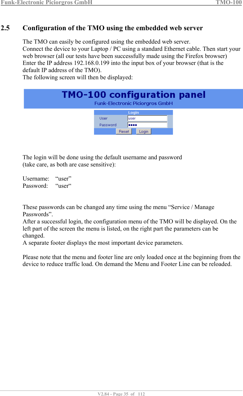
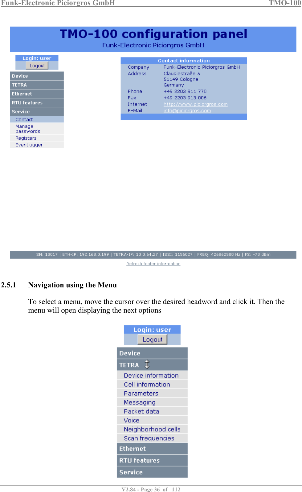
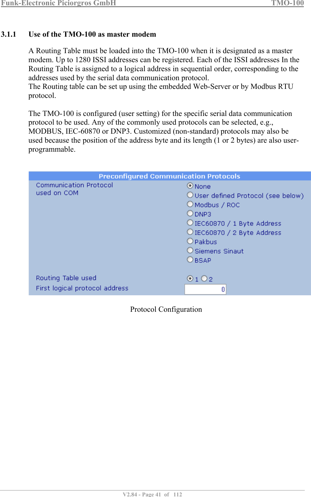
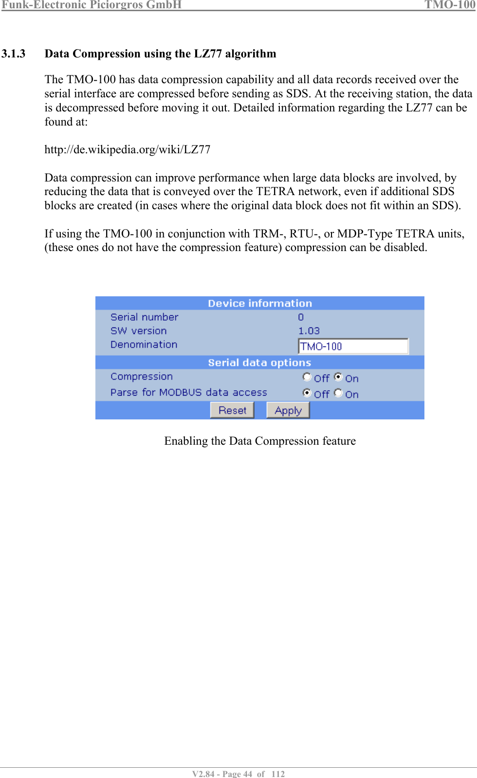
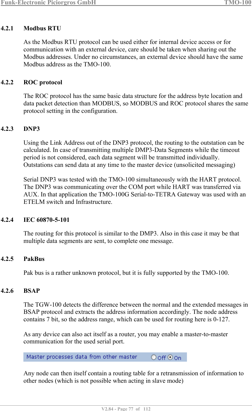
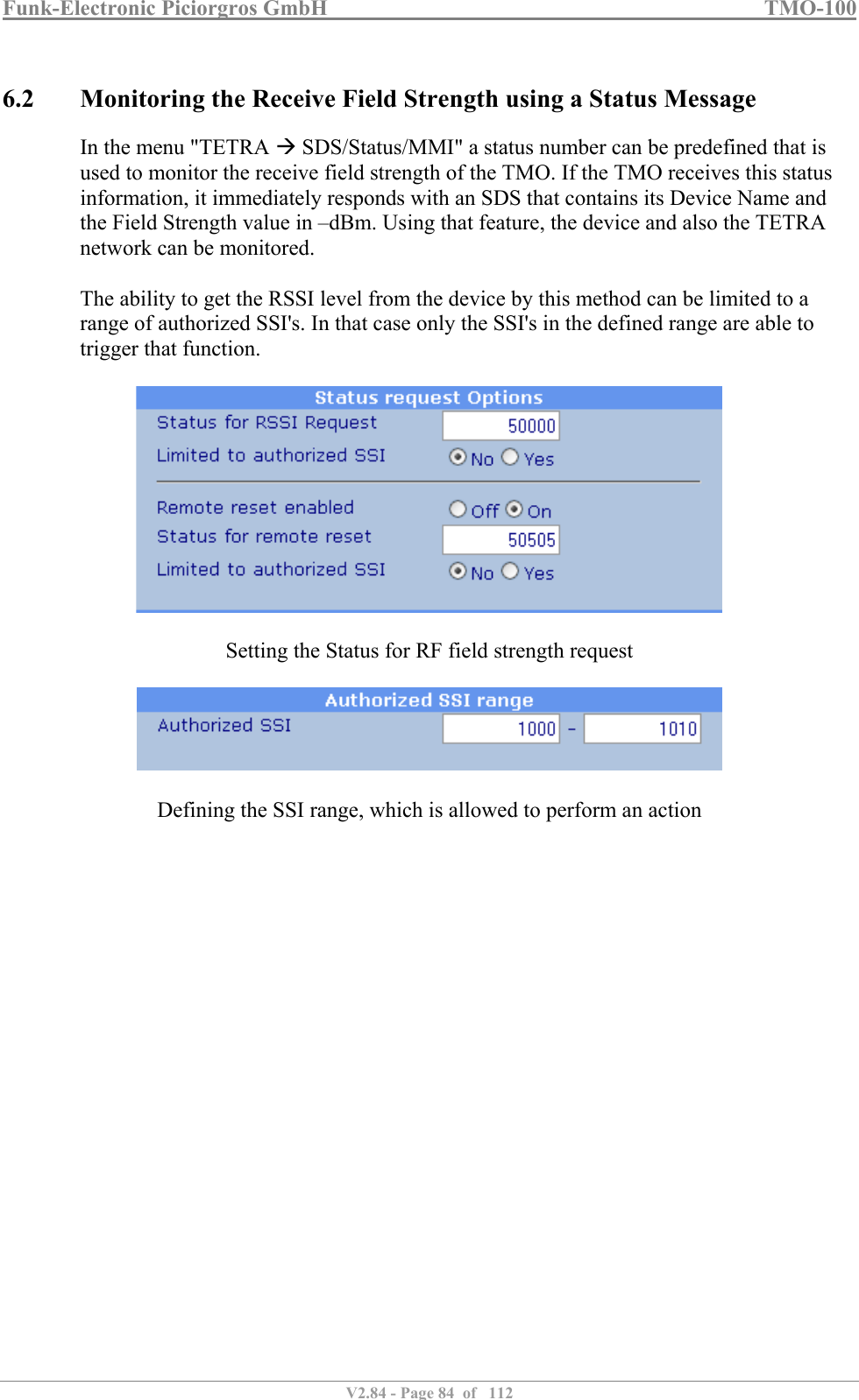
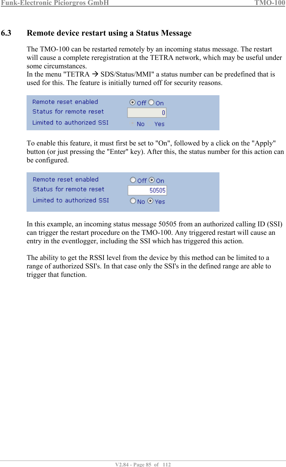
![Funk-Electronic Piciorgros GmbH TMO-100 V2.84 - Page 80 of 112 5 Configuring the TMO-100 5.1 Configuring the TMO-100 through the Integrated Web Server The adjustable parameters of the TMO-100 can be configured through the integrated Web server from a conventional browser. This can be done either over its Ethernet interface or over the TETRA network, in packet data mode. The Web server responds to queries through Port 80. Example: The TMO-100 is delivered with a factory-installed IP address 192.168.0.199 for the Ethernet interface. A PC connected to this interface has the e.g. IP address 192.168.0.26. To configure the TMO-100, type http//192.168.0.199 in the address window of the browser and hit "Enter". If necessary, a fixed IP address in the range 192.168.0.xxx may need to be assigned to the connected PC. The TMO-100 can be connected using a 1:1 patch cable if connecting to the PC via a switch or hub. If connecting to a PC directly, use a crossed cable. If the TMO-100 is operated in “Packet-Data Mode” with an assigned IP address, it can be configured locally or remote over the TETRA Network. For example, if the TMO-100 has the IP address 10.0.66.17 on the TETRA network side, a remote PC can access this TMO-100 via another TMO-100 (here “the another” TMO-100 is just used to link the PC to the TETRA network). In that case on the browser input line of the PC http://10.0.66.17 followed by [RETURN] would access the Web server of the remote TMO-100 that has to be configured. Note that a registered port forwarding linkage has higher priority than the internal functions of the TMO-100. Therefore, if Port 80 is assigned in the Port Forwarding Table to an IP address of the local Ethernet, then the Web server of the TMO-100 is no longer accessible remotely over the TETRA network.](https://usermanual.wiki/Funk-Electronic-Piciorgros/TMO-100.User-Manual/User-Guide-3291480-Page-80.png)
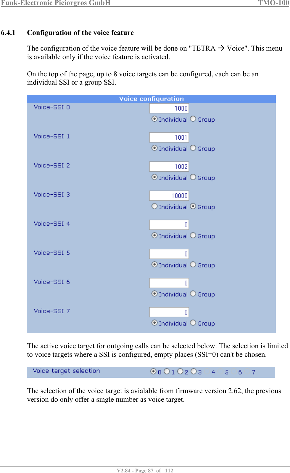
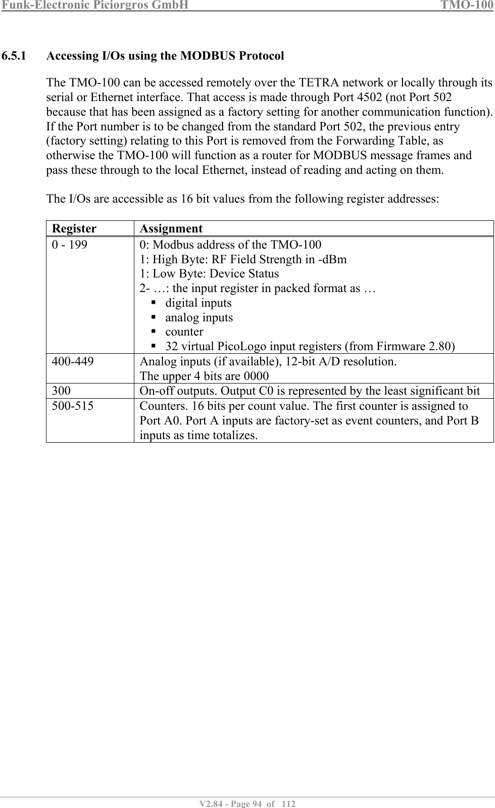
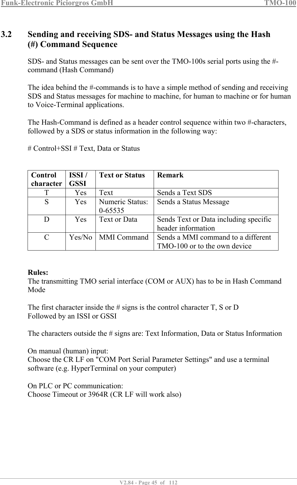
![Funk-Electronic Piciorgros GmbH TMO-100 V2.84 - Page 93 of 112 6.5 Control and Measurement I/O (RTU Functionality) (Note: in the following paragraph Ports A, B, C, & D are not to be confused with IP ports mentioned elsewhere in this document). A version of the TMO-100 is optionally available with control and measurement inputs and outputs integrated with the modem. The basic version has 16 on-off inputs (Ports A and B) and 8 on-off outputs (Port C). A further optional version has Port D, which can be ordered as 8 additional on-off outputs, or as 4 analog inputs. Each of the 16 on-off inputs of Port A have independent event counting functions that can be enabled by the user. Port A inputs counters operate as event counters, while Port B counters operate as time-totalizing counters. The maximum counting rate [input pulse rate] is 10 Hz. The control and measurement I/O can be accessed using any of the following protocols: MODBUS RTU through the serial interface or Ethernet interface, or over the TETRA network. IEC-60870-5-101 through the serial interface or over the TETRA network. IEC-60870-5-104 (future: not presently supported) DNP3 (future: not presently supported) The RTU function of the TMO-100 can be configured so that a status change of an on-off input can cause an appropriate message to be sent (for example) to a TMO-100 Master Modem that has MODBUS access enabled, and stored there in a MODBUS Alarm List. Alarms can then be sent to a control system for appropriate action.](https://usermanual.wiki/Funk-Electronic-Piciorgros/TMO-100.User-Manual/User-Guide-3291480-Page-93.png)