Furuno USA 9ZWRTR112 Transceiver for Radar Sensor User Manual IME 36460 A
Furuno USA Inc Transceiver for Radar Sensor IME 36460 A
Contents
- 1. User Manual
- 2. User Manual II
User Manual

www.furuno.com
A
ll brand and product names are trademarks, registered trademarks or service marks of their respective holders.
Installation Manual
RADAR SENSOR
Model DRS6A X-Class
SAFETY INSTRUCTIONS ................................................................................................ i
SYSTEM CONFIGURATION .......................................................................................... iii
EQUIPMENT LISTS........................................................................................................ iv
1. INSTALLATION AND WIRING................................................................................... 1
1.1 Mounting Considerations ......................................................................................................1
1.2 Included Items.......................................................................................................................3
1.3 Required Tools and Materials...............................................................................................4
1.4 Fastening the Radiator to the Radiator Bracket....................................................................5
1.5 Mounting the Antenna Unit ...................................................................................................7
1.6 Wiring..................................................................................................................................10
2. INITIAL SETUP......................................................................................................... 13
2.1 Initial Setup for TZT9/TZT14/TZTBB ..................................................................................13
2.2 Initial Setup for TZTL12F/TZTL15F ....................................................................................16
3. MAINTENANCE, TROUBLE SHOOTING ................................................................ 18
3.1 Maintenance .......................................................................................................................19
3.2 Troubleshooting ..................................................................................................................19
3.3 Replacement of Fuse..........................................................................................................20
3.4 Life of Parts.........................................................................................................................20
SPECIFICATIONS ..................................................................................................... SP-1
OUTLINE DRAWING................................................................................................... D-1
INTERCONNECTION DIAGRAM ................................................................................ S-1
i
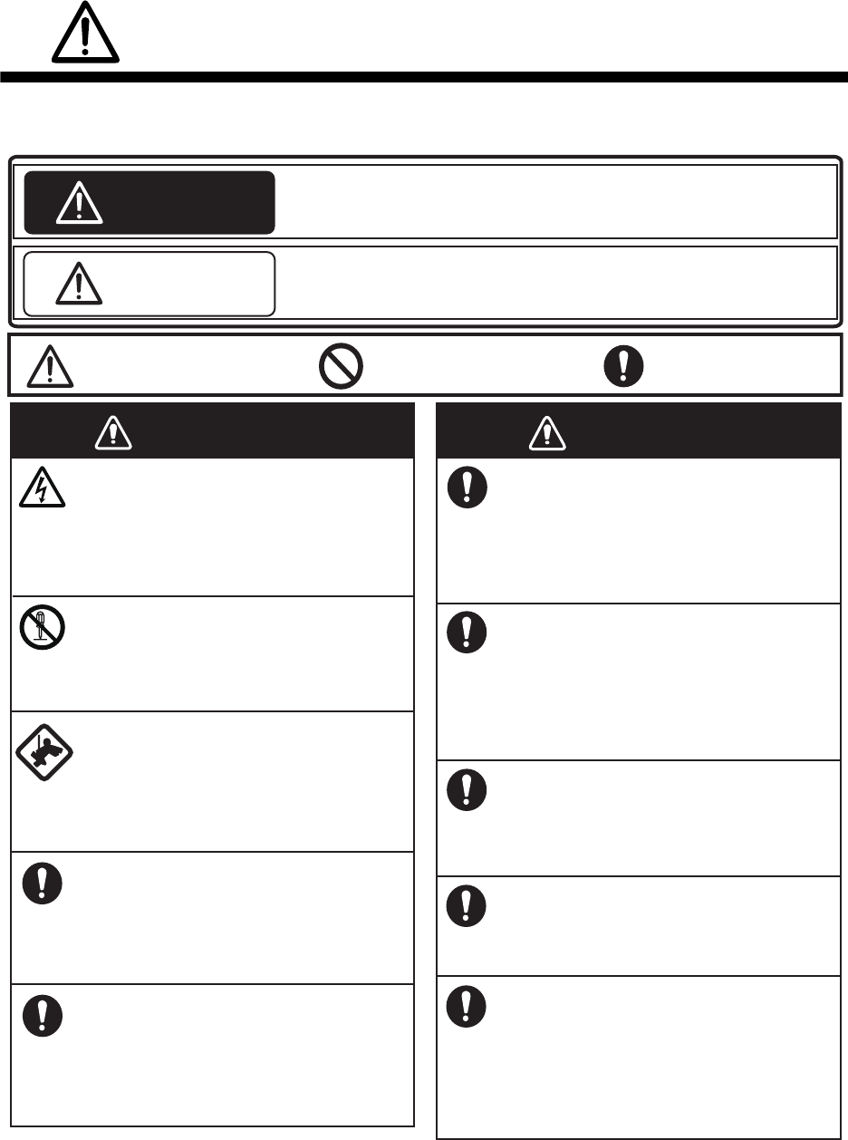
SAFETY INSTRUCTIONS
Mandatory Action
Prohibitive Action
WARNING
CAUTION
Warning, Caution
WARNING
The installer of the equipment must read the safety instructions before attempting to
install the equipment.
Indicates a potentially hazardous situation which, if not avoided,
could result in death or serious injury.
Indicates a potentially hazardous situation which, if not avoided,
can result in minor or moderate injury.
WARNING
Turn off the power at the
switchboard before beginning the
installation.
Fire or electrical shock can result if
the power is left on.
Do not open the equipment
unless you are well familiar with
electrical circuits.
Only qualified personnel should
work inside the equipment.
Be sure that the power supply is
compatible with the voltage rating
of the equipment.
Connection of an incorrect power
supply can cause fire or damage the
equipment.
Use only the specified power and
signal cable.
Fire or damage to the equipment
can result if a different cable is used.
Wear a safety belt and hard hat
when working on the antenna
unit.
Serious injury or death can result if
someone falls from the radar mast.
Do not disassemble or modify the
equipment.
Fire, electrical shock or serious
injury can result.
Construct a suitable service
platform from which to install the
antenna unit.
Serious injury or death can result if
someone falls from the radar mast.
Keep the objects away from the
antenna unit, so as not to impede
rotation of the antenna.
Fire, electrical shock or serious
injury can result.
Use the proper fuse.
Use of a wrong fuse can damage
the equipment or cause fire.
Do not depend one navigation
device for the navigation of the
vessel.
For the safety of vessel and crew,
the navigator must check all aids
available to confirm position.
SAFETY INSTRUCTIONS
ii
Ground the equipment to prevent
mutual interference.
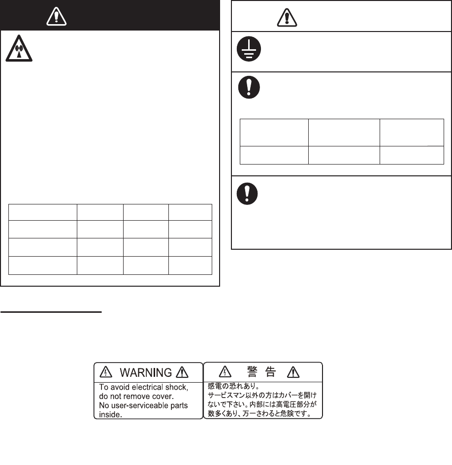
The radar antenna emits
electromagnetic radio frequency
(RF) energy which can be
harmful, particularly to your eyes.
Never look directly into the
antenna aperture from a close
distance while the radar is in
operation or expose yourself to
the transmitting antenna at a
close distance.
Distances at which RF radiation
levels of 100, 50 and 10 W/m2 exist
are given in the table below.
WARNING LABEL
A warning label is attached to the antenna unit. Do not remove the label.
If the label is missing or damaged, contact your dealer about replacement.
Name: Warning Label (2)
Type: 03-129-1001-3
Code No: 100-236-743
It is recommended that you
connect the antenna unit to a
disconnecting device (circuit
breaker, etc.) to control the
power.
CAUTION
Observe the following compass safe
distances to prevent deviation of a
magnetic compass:
WARNING
0.1m
XN10A
3m0.5m
100 W/m250 W/m210 W/m2
Radiator
1.40 m
DRS6A X-Class
0.90 m
Model Standard
compass
Steering
compass
XN12A
XN13A
N/A 2.2m0.4m
N/A 1.9m0.2m
iii
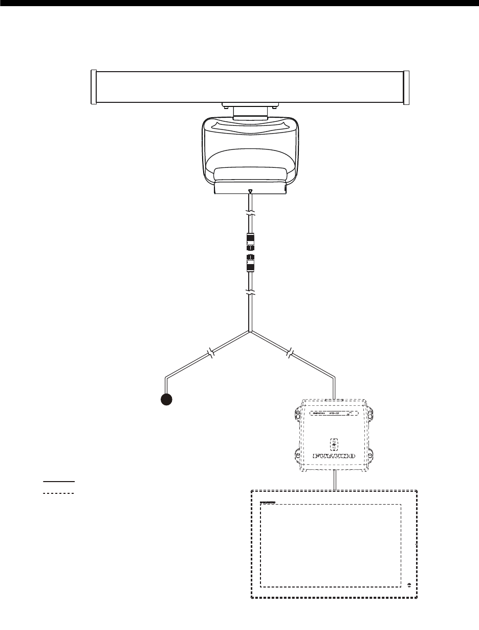
SYSTEM CONFIGURATION
The DRS6A X-Class is compatible with the FURUNO Multi Function Displays shown below. The
combination with other models may not operate properly.
• NavNet TZtouch: TZT9, TZT14, TZTBB
• NavNet TZtouch2: TZTL12F, TZTL15F
: Standard supply
: Optional or local supply
Antenna Unit
RSB-134
Multi Function Display
NavNet TZtouch/Navnet TZtouch 2
Multi Function Display
NavNet TZtouch/Navnet TZtouch 2
24 VDC24 VDC
Ethernet HUB
HUB-101
iv
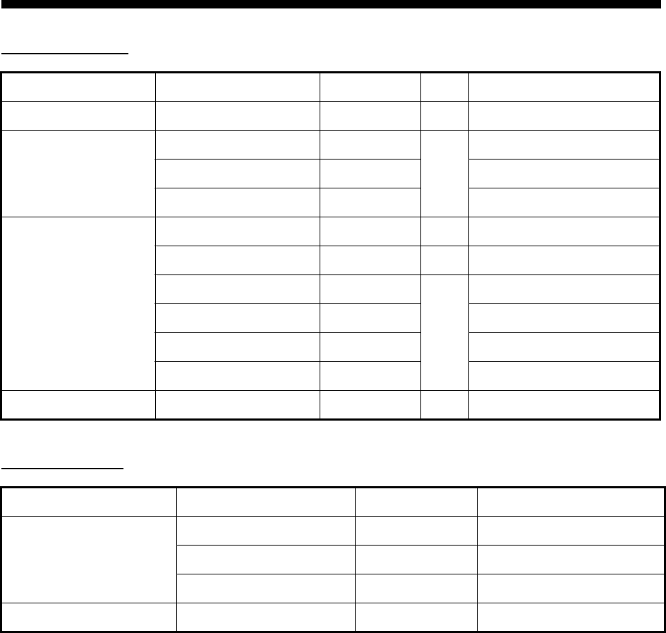
EQUIPMENT LISTS
Standard supply
Optional supply
*: After the wiring, it is required to wind the vinyl tape around the LAN connector to waterproof.
Name Type Code No. Qty Remarks
Scanner Unit RSB-134 - 1
Radiator XN10A -
1
3.4 ft
XN12A - 4 ft
XN13A - 6 ft
Installation Materials TBD TBD 1 For scanner unit
TBD TBD 1 For radiator
CP03-36400 000-027-211
1
Power/LAN cable, 10 m
CP03-36410 000-027-212 Power/LAN cable, 15 m
CP03-36420 000-027-213 Power/LAN cable, 20 m
CP03-36430 000-027-214 Power/LAN cable, 30 m
Spare Parts TBD TBD 1 Fuse
Name Type Code No. Remarks
LAN Cable MOD-Z072-020+ 001-167-880-10 2 m
MOD-Z072-050+ 001-167-890-10 5 m
MOD-Z072-100+ 001-167-900-10 10 m
Joint Box TL-CAT-012 000-167-140-10 For LAN cable extension*
1
1. INSTALLATION AND WIRING
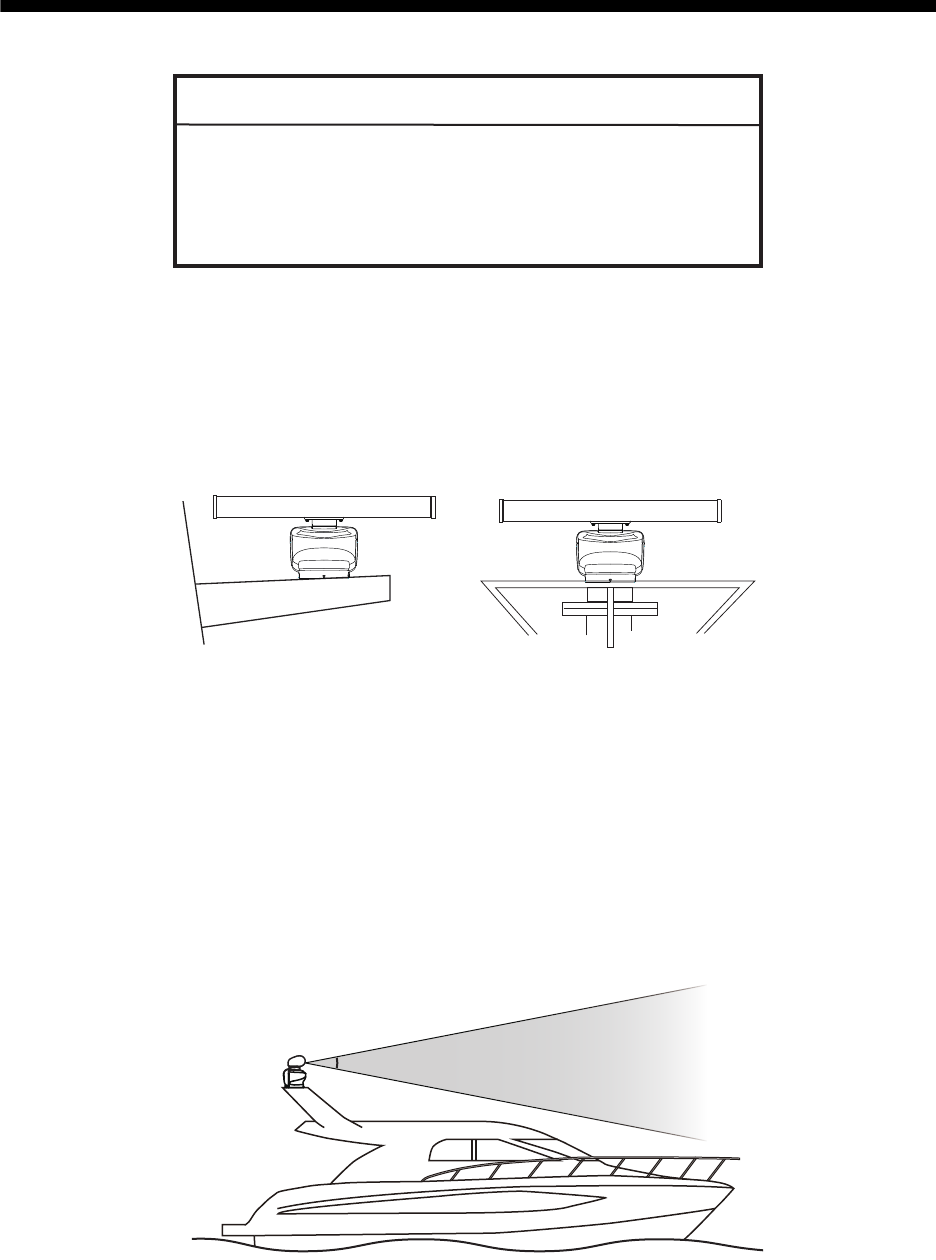
1.1 Mounting Considerations
Select a mounting location, keeping in mind in the following points:
• Install the antenna unit on the hardtop, radar arch or on a mast on an appropriate
platform.
• Locate the antenna unit where there is a good all-round view with, as far as possi-
ble, no part of the ship’s superstructure or rigging intercepting the scanning beam.
Any obstruction will cause shadow sectors and decrease the radiator’s performance
(beam width, side-lobe level, etc.). The loss of the radiator’s performance cause the
deterioration of the radar’s observation (bearing resolution, etc.) and false echoes.
A mast for instance, with a diameter considerably less than the horizontal beam
width of the radiator, will cause only a small shadow sector, but a horizontal spread-
er or cross trees in the same horizontal plane as the antenna unit would be a much
more serious obstruction; you would need to place the antenna unit well above or
below it. Be sure there are no metallic objects near the antenna.
• It is rarely possible to place the antenna unit where a completely clear view in all
directions is available. Thus, you should determine the angular width and relative
bearing of any shadow sectors for their influence on the radar at the first opportunity
after fitting.
NOTICE
Do not apply paint, anti-corrosive sealant or contact
spray to coating or plastic parts of the equipment.
Those items contain organic solvents that can damage
coating and plastic parts, especially plastic connectors.
(a) Common mast (b) Radar mast
Vertical beam angle = 22°
1. INSTALLATION AND WIRING
2
• In order to reduce the chance of picking up electrical interference, avoid where pos-
sible routing the power cable near other electrical equipment on-board. Also, avoid
running the cable in parallel with other power cables.
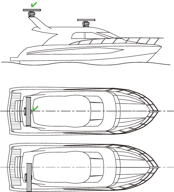
• It is not recommended to install the antenna unit on the hardtop of a cabin. Vibra-
tions from the antenna unit will pass through the hardtop and into the cabin.
• It is not recommended to install the antenna unit on the off-center position. The ra-
dar echoes on the display may not be aligned with the actual target’s bearing.
• Select a location that does not allow water to accumulate at the base of the antenna
unit.
• A magnetic compass will be affected if the antenna unit is too close to the compass.
Observe the compass safe distances mentioned in the SAFETY INSTRUCTIONS
to prevent interference to a magnetic compass.
• Do not paint the radiator to ensure proper emission of the radar waves.
• Make the maintenance space shown in the outline drawing for maintenance and
checking purpose.
• When this antenna unit is to be installed on a large vessel, consider the following
points:
• The supplied power/LAN cable runs between the antenna unit and display (or
ethernet HUB) and comes in lengths of 10 m, 15 m, 20 m or 30 m. Select the
length when purchasing.
• Deposits and fumes from a funnel or other exhaust vent can adversely affect the
aerial performance and hot gases may distort the radiator portion. The antenna
unit must not be mounted where the temperature is more than 55°C (131°F).
Not recommended
Not recommended
Not recommended
1. INSTALLATION AND WIRING
3
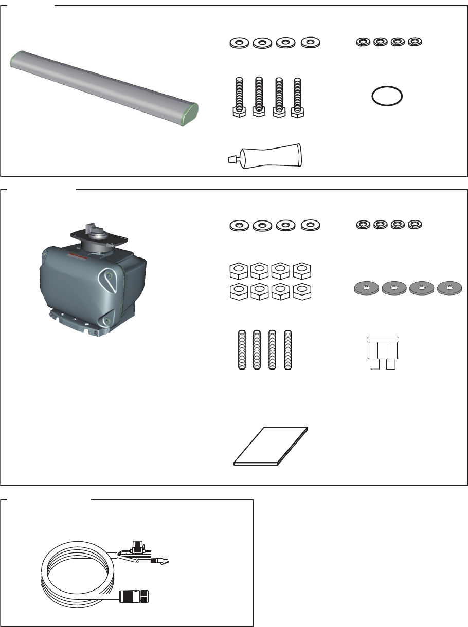
1.2 Included Items
•
Radiator* (1 pcs):
3.4 ft, 4 ft or 6 ft
•
Scanner Unit (1 pcs)
Radiator
• O-ring (1 pcs)
• Flat washer (M8, 4 pcs) • Spring washer (M8, 4 pcs)
• Hex. bolt (M8×30, 4 pcs)
• Silicone rubber (1 pcs)
Scanner Unit
• Stud bolt (M12×60, 4 pcs)
• Flat washer (M12, 4 pcs) • Spring washer (M12, 4 pcs)
• Hex nut (M12, 8 pcs) • Corrosion-proof rubber pad
(4 pcs)
• Spare fuse (1 pcs)
(5 A)
• Documents (1 set):
Mounting template is included.
Power/LAN cable
• Power/LAN cable* (1 pcs): 10 m, 15 m, 20 m or 30 m *: Select the length when purchasing.
1. INSTALLATION AND WIRING
4
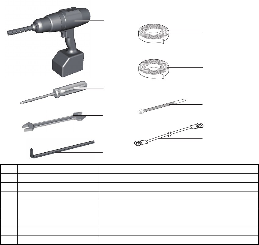
1.3 Required Tools and Materials
Prepare the tools and materials shown below to install the antenna unit.
No. Name Remarks
1Electrical drill For making the mounting holes, drill bit: 15 mm
2Phillips-head screw driver #3, for fixing the cable cover
3Wrench For M10 (Hex. size 17 mm) and M12 (Hex. size 19 mm)
4Hex. L-wrench For fixing the stud bolts (Hex. size 6 mm)
5Self-vulcanizing tape For waterproofing the junction of connectors
6Vinyl tape
7Cable tie For fixing the cables
8 Ground wire IV-2sq
1
2
3
5
7
4
6
8
1. INSTALLATION AND WIRING
5
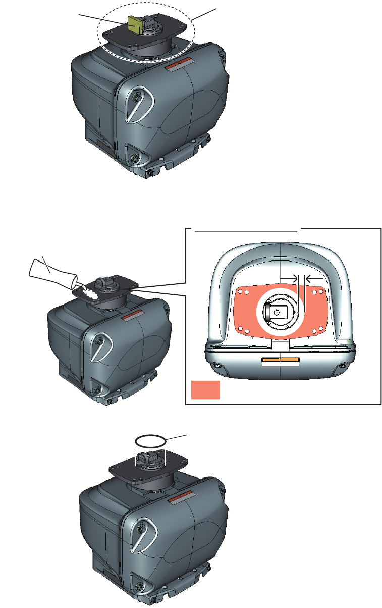
1.4 Fastening the Radiator to the Radiator Bracket
1. Remove the radiator cap from the radiator bracket.
2. Apply the silicone rubber to the surface of the radiator bracket as shown in the fig-
ure below.
3. Set the O-ring to the radiator bracket.
Radiator bracket
Radiator cap
Silicone rubber
Top view: Scanner unit
10 mm10 mm
: Silicone rubber application area
O-ring
1. INSTALLATION AND WIRING
6
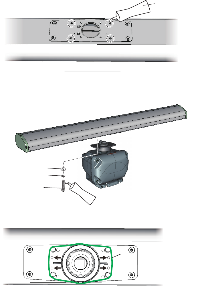
4. Apply the silicone rubber to the thread holes on the bottom of the radiator (4 loca-
tions).
5. Apply the silicone rubber to the hex. bolts (M830, 4 pcs).
6. Fasten the radiator to the radiator bracket, using the hex bolts (M830), flat wash-
ers (M8) and spring washers (M8).
7. Apply the silicone rubber to the holes and junction between the radiator and radi-
ator bracket.
Bottom view: Radiator
Silicone rubber
Flat washer
Spring washer
Hex. bolt:
Apply the silicone
rubber.
Apply the silicone rubber to
the junction between the
radiator and radiator bracket.
Apply the silicone rubber to
the junction between the
radiator and radiator bracket.
Hole
Hole
1. INSTALLATION AND WIRING
7
1.5 Mounting the Antenna Unit
The antenna unit can be mounted using the fixing holes on the outside (200 200 mm)
or inside (140 150 mm) the antenna unit. Normally, use the outside fixing holes.
When 140 150 mm fixing holes already exist on the mounting platform, use the in-
side fixing holes.
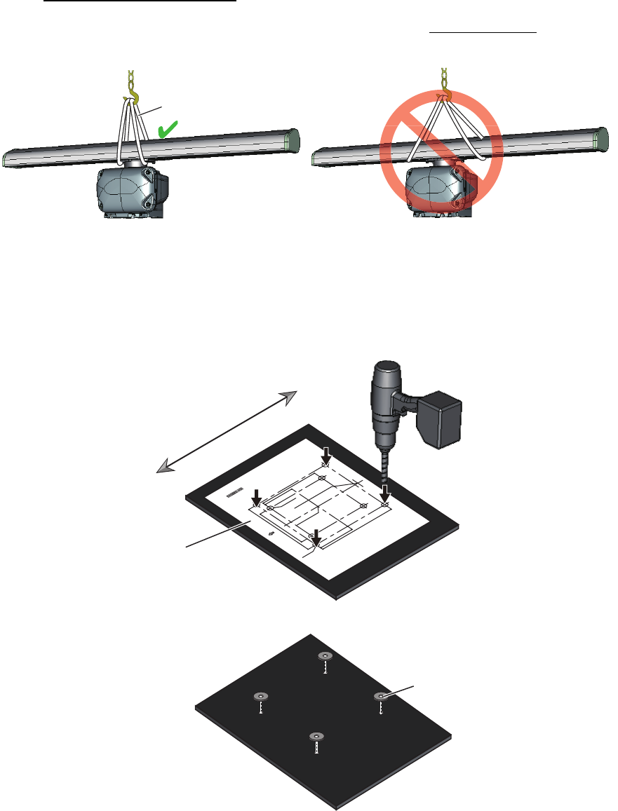
Hoisting the antenna unit
• When you hoist the antenna unit, set belt slings to the radiator bracket. Do not set
belt slings to the radiator - the radiator may get damaged.
• Hoist the antenna unit slowly. If the antenna unit is hoisted too quickly, shock is ap-
plied to the radiator bracket, which can damage the bracket.
1. Use the mounting template to drill four fixing holes in the mounting location.
Note: The holes must be parallel with the fore and aft line.
2. Attach four corrosion-proof rubber pads to the mounting holes.
WRONG: Belt slings are set to the radiator. OK: Belt slings are set to the radiator bracket.
Belt sling
CABLE ENTRANCE AT SCANNER FOR DRS4A/6A/12A/25A
䝇䜻䝱䝘ഃ䜿䞊䝤䝹ᑟධཱྀ䠄㻰㻾㻿㻠㻭㻛㻢㻭㻛㻝㻞㻭㻛㻞㻡㻭䛾䜏䠅
PP'')
PP'')
sPP'')
PP'')
sPP'')
CENTER OF ANTENNA ROTATION
䜰䞁䝔䝘ᅇ㌿୰ᚰ
PP'')
ྲྀ✰
4-䃥15
FIXING HOLES
ྲྀ✰䚷㻔⏝㻕
4-䃥15 (#: 4 places)
FIXING HOLES
( FOR RETROFITTING)
Note: This template may have expanded or shrunk slightly.
Please confirm dimensions before use.
ὀព㻦㻌㻌ᮏᆺ⣬䛿ಖᏑ≧ែ䛻䜘䜚ⱝᖸఙ⦰䛩䜛ሙྜ䛜䛒䜚䜎䛩䚹
㻌㻌㻌㻌㻌㻌㻌㻌㻌⏝䛾㝿䛻䛿ᑍἲ䜢☜ㄆ䛧䛶䛟䛰䛥䛔䚹㻌
BOW
⯪㤳᪉ྥ
June 2015 Printed in Japan
C32-00703-A1
DRSシリーズ レーダーセンサー(オープン型)
ᆺ⣬
DRS SERIES OPEN RADAR SENSOR
MOUNTING TEMPLATE
䢲䢲䢲䢳䢸䢹䢶䢷䢻䢳䢲
BowBow
SternStern
Mounting template
Corrosion-proof rubber pad
1. INSTALLATION AND WIRING
8
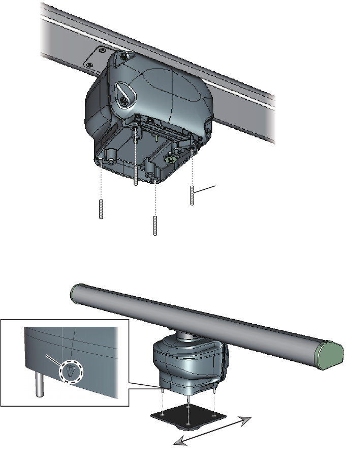
3. Insert four stud bolts (M1260) into the threaded holes in the antenna unit.
4. Put the antenna unit on the mounting platform with the BOW mark on the unit
aligned with the ship’s bow.
Stud bolt
BOW markBOW mark
BowBow
SternStern
1. INSTALLATION AND WIRING
9
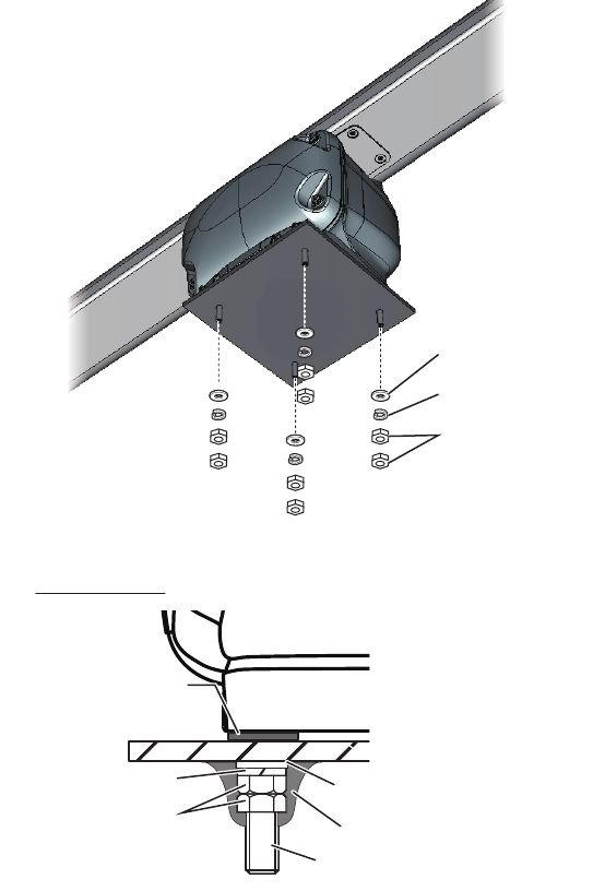
5. Fix the antenna unit, using the flat washers (M12), spring washers (M12), and hex.
nuts (M12).
6. Apply the silicone rubber to the flat washers, spring washers, and hex. nuts.
Flat washer
Spring washer
Hex. nut
Silicone rubber
Corrosion-proof
rubber pad
Flat washer
Spring washer
Hex. nut
Stud bolt
Detailed view
1. INSTALLATION AND WIRING
10
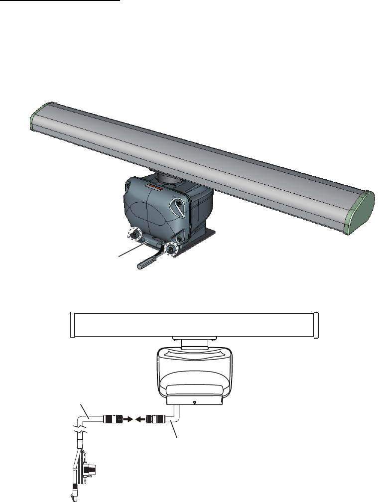
1.6 Wiring
Wiring considerations
• Turn off the power at the switchboard before beginning the wiring.
• The power/LAN cable has connectors. Do not cut the power/LAN cable.
• When you replace the DRS4A/6A/12A/25A with the DRS6A X-Class, the existing
cable cannot be used. Use the power/LAN cable supplied with the DRS6A X-Class.
1. Unfasten two screws to remove the cable cover.
2. Connect the power/LAN cable to the antenna cable that is pre-attached to the an-
tenna unit.
Cable coverCable cover
Antenna cable:
Pre-attached to the antenna unit.
Power/LAN cable