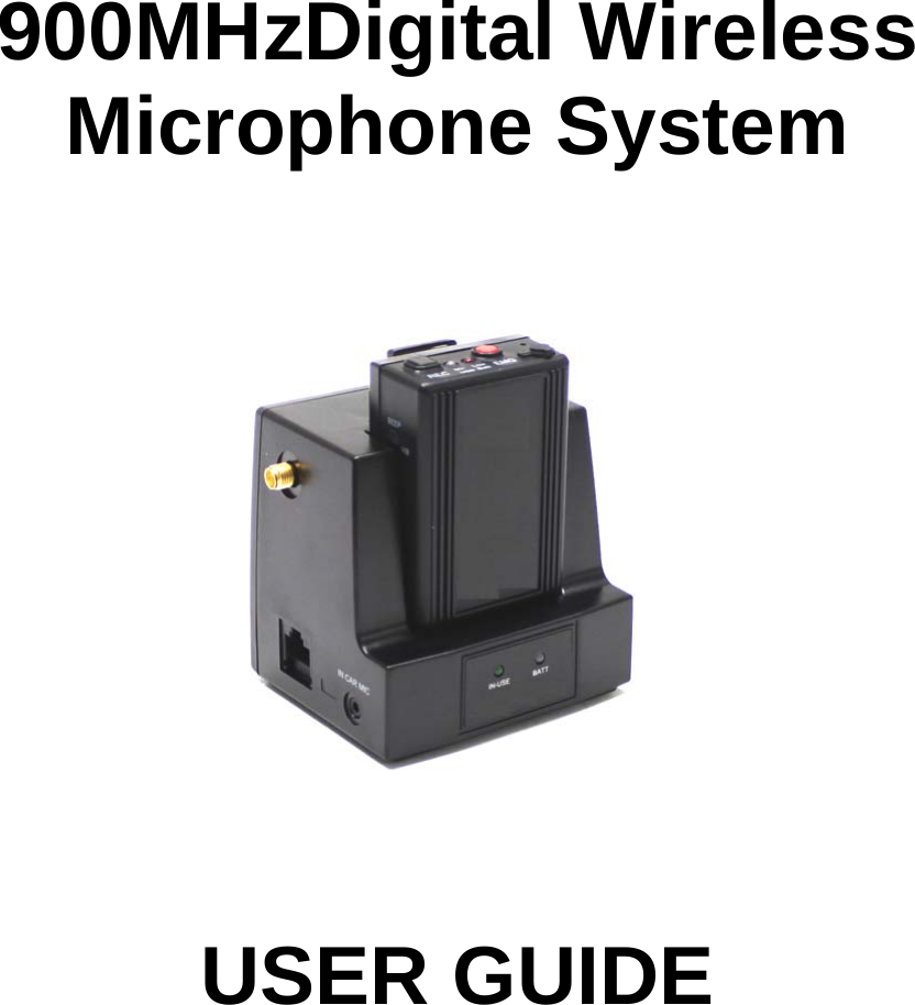
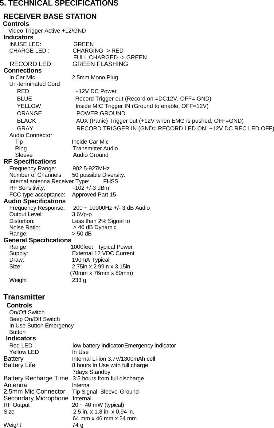
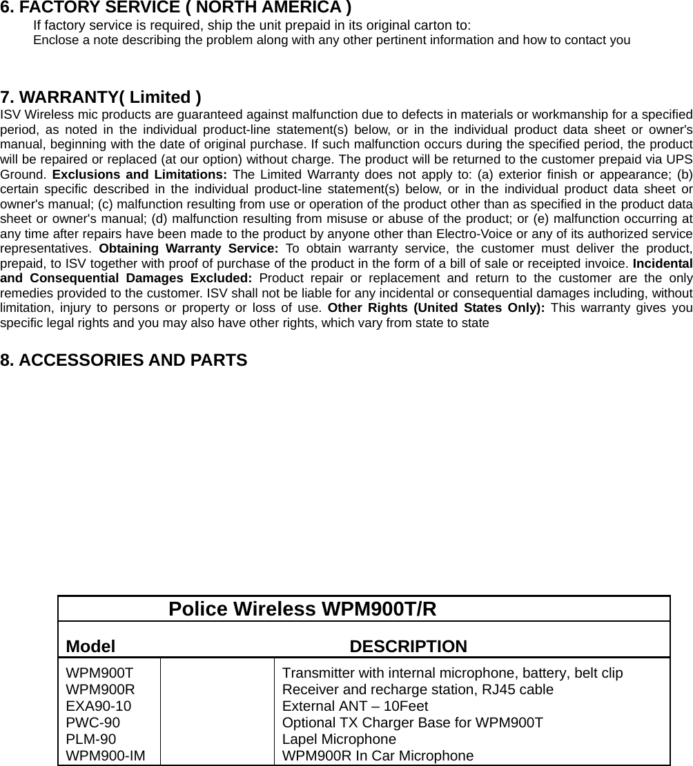
GPI KOREA GPWM-900T Wireless Transmitter User Manual 900police Generic Manual fcc

GPI KOREA, Inc Wireless Transmitter 900police Generic Manual fcc

Users Manual

     900MHzDigital Wireless Microphone System                              USER GUIDE
TABLE OF CONTENTS  1. Description of the units ....................................... ........................3 1. Quick Set Up and Operation .......................................................4   2. Installation....................................................................................5   3. Guidelines For Best Performance................................................6   4. Troubleshooting Guide.................................................................7  5. Technical Specifications...............................................................8   6. Factory Service ............................................................................9 7. Warranty......................................................................................9  8. Accessories and Parts ............................... ...................................9
FCC NOTICE          THIS DEVICE COMPLIES WITH PART 15 OF THE FCC RULES.     OPERATION IS SUBJECT TO THE FOLLOWING TWO CONDITIONS: (1) THIS DEVICE MAY NOT CAUSE HARMFUL INTERFERENCE, AND (2) THIS DEVICE MUST ACCEPT ANY INTERFERENCE RECEIVED, INCLUDING INTERFERENCE THAT MAY CAUSE UNDERSIRED OPERATION.  < Part 15.106>          This equipment has been tested and found to comply with the limits for a Class B digital device, pursuant to part 15 of the FCC Rules. These limits are designed to provide reasonable protection against harmful interference in a residential installation. This equipment generates, uses and can radiate radio frequency energy and, if not installed and used in accordance with the instructions, may cause harmful interference to radio communication. However, there is no guarantee that interference will not occur in a particular installation. If this equipment does cause harmful interference to radio or television reception, which can be determined by turning the equipment off and on, the user is encouraged to try to correct the interference by one or more of the following measures :  - Reorient or relocate the receiving antenna. - Increase the separation between the equipment and receiver. - Connect the equipment into an outlet on a oircuit difference from       that to which the receiver is connected. - Consult the dealer of an experienced radio/TV technician for help.  NOTE : The manufacturer is not responsible for any radio or TV interference caused by unauthorized modifications to this equipment. Such modifications could void the user's authority to operate the equipment.
DESCRIPTION  Base (Receiver)                          Transmitter                                 Green LED: In-use, Record RED LED: Charging Green LED: Full chargeTerminal For charging Antenna Connection Modular Jack Audio Jack Input Record Button Lapel Mic. Cover Emergency Button Green: In-use (Light On)        Record (Flashing) RED LED: Out of Range  RED LED: Low BatteryAudible and Vibration Selectable Switch Power On/Off Switch
1. QUICK SET UP AND OPERATION Synching Up the Transmitter and Base The synch operation only needs to be performed the first time a system is used, or a new bodypack is used with a base previously synched to another bodypack. Do not perform the synch operation multiple times; it only needs to be done one time when a new bodypack is used with a new base.    1)    Turn the transmitter power switch to ON and place the transmitter in the recharge cradle of the base. The transmitter goes in the base with the belt clip facing out.   2)    The recharge LED will light (Green if fully charged, Red if charging). Leave the transmitter in the cradle for 4 hours for a full charge. 3)    Press the REC button on the transmitter and hold until the In-Use LED on the transmitter and base start to flash, then release the button.   4)    After a few seconds the light will stop flashing, and a beep will sound (If the beep is enabled).   5)    The transmitter and base are now synched and will continue to be until another transmitter is linked to that base.    Normal Operation 1)  With the transmitter synched up, remove it from the cradle, plug in the lapel microphone (if used) and place the transmitter on your belt.   2)  When you remove Transmitter from the cradle, The TR and Base’s In-USE LED will light a constant Green and you will hear short beep. To start the recording, press the REC button and the In-Use LED will blink in green. 3)  To end recording, press the REC button and the In-Use LED will light a constant green. 4)  At the end of your shift turn the transmitter off and replace it in the charging cradle.  Out of Range 1)    The transmitter will alert you with Audible warning beeps (two tone) and the In-Use LED will blink in red. 2)    Move closer to the receiver base and the link will be re-established once you return to normal   range. The In-Use LED will light constant green when link is back to normal operation.   3)    If the link is not re-established within 30 seconds, the transmitter and receiver will return to standby mode.  4)    If you went out of range in Standby mode, or the unit reverted to standby mode, re-enter normal range and press the In-Use button. Operation will return to normal.   5)    If you will be out of range for a long period of time, turn the bodypack off.    Low Battery Warning  1)    If the transmitter Low BATT indicator (red) starts flashing or you hear warning beeps, return the transmitter to its cradle on the receiver to fully charge the transmitter.   2)    The Charge LED indicator will light constant green when the unit is fully charged.    EMG Panic Button (if wired for use in your vehicle) 1)    The EMG or Panic Button can be programmed to do many things but may not be connected in your vehicle. Check with your technical department to understand what this button will control before you use it.  2)    In Record mode: Press the EMG button on the transmitter, a beep will sound and the relay will be triggered at the receiver.   3)    In Standby mode: Press the EMG button on the transmitter, a beep will sound, the green In-Use indicator will blink and the relay will be triggered at the receiver.    Disabling the Beep Sound On the Transmitter   1)    All of the audible beep signals on the transmitter can be disabled by setting the BEEP switch to the off position.    Record Trigger (if video recording equipment supports)    1) The Record trigger feature is used to turn on recording whenever the video recorder is turned on.   Some video record units can be triggered by other events (lights and siren being turned on etc.) and     ensures the microphone starts recording at the same time.     The transmitter must be turned on and in standby mode.   2) A +12V signal on the line means the microphone is Record off.   3) 0V or ground on the line turns on the microphone is Record on.
2. INSTALLATION    PIN DESCRIPTION OF THE BASE OUTPUT PORT     Connector wire (RJ45) Pin #1 : Transmitter Audio out   Pin #2 : In Car Mic. Audio out   Pin #3 : 12V DC_IN   Pin #4 : Ground     Pin #5 : Record Trigger OUT   Pin #6 : Record Trigger IN   Pin #7 : Panic Trigger Out   Pin #8 : In Car Mic. Trigger IN    Terminated Connector ( Optional ) Type A   1)    Wire the un-terminated signal wires to the control unit according to the signal chart. 5 Amp fast blow fuse is recommend in the 12VDC power supply line to protect the equipment.            2)  Plug the 3.5mm stereo plug into the audio input jack of the recording device.      3)  If it is to be used, plug in the in-car microphone into the In-Car Mic jack in the side of the receiver base. 4)  Turn on the transmitter and place it in the charging cradle with the beltclip facing out. The Charge LED will light if there is power. If the LEDs do not come on, check the connections and repeat.  Description   Position  Audio Ground  Sleeve Transmitter Audio   Ring  Inside Car Mic. Audio    Tip   8 1 8 1
Type B Wire the un-terminated signal wires to the control unit according to the signal chart. A 5 Amp fast blow fuse is recommend in the 12VDC power supply line to protect the equipment.             Type C Wire the un-terminated signal wires to the control unit according to the signal chart. A 5 Amp fast blow fuse is recommend in the 12VDC power supply line to protect the equipment.                          1)  Plug the 3.5mm stereo plug into the audio input jack of the recording device.      2)  If it is to be used, plug in the in-car microphone into the In-Car Mic jack in the side of the receiver base. 3)  Turn on the transmitter and place it in the charging cradle with the beltclip facing out. The Charge LED will light if there is power. If the LEDs do not come on, check the connections and repeat. Installation is complete. Refer to Operation Section for more information.   3. GUIDELINES AND RECOMMENDATIONS FOR BEST PERFORMANCE  Compatibility  The transmitter and receiver must synchronize to work together (see Synch process on page 3). The synch operation only needs to be performed the first time a system is used, or when a new bodypack is used with a base previously synched to another bodypack. Do not synch multiple times, just once until a new bodypack is used. Any Base can be synchronized with any Transmitter.   Description   Position  Audio Ground  Sleeve Transmitter Audio   Ring  Inside Car Mic. Audio    Tip   Pin #1 : Transmitter Audio out   Pin #2 : In Car Mic. Audio out   Pin #3 : 12V DC_IN   Pin #4 : Ground   Pin #5 : Record Trigger Out   Pin #6 : Record Trigger IN   Pin #7 : Panic Trigger Out   Pin #8 : In Car Mic. Trigger IN   8 1
Using Multiple Wireless Systems   The WPM900 system has 100 possible “channels” that are really different frequency hopping schemes.    Potential Sources of Interference There are many potential sources of interference for your wireless system. Any electronic product that contains digital circuitry including digital signal processors (reverb/multi-effects units), electronic keyboards, digital lighting controllers, CD and DVD players, and computers, all emit RF energy that can adversely affect the performance of your wireless system. It is always best to place the receiver as far away as possible from these devices to minimize potential problems.   The WPM900 operates in the 900MHzISM band and other devices in that band may interfere. The spread spectrum technique used in the WPM900 is very robust and should operate even in the presence of other 900MHz devices such as walkie-talkies, LANs, cordless phones, etc. in the area.    Battery Recommendations   The Lithium-Ion battery built into the WPM900 transmitter will work at full capacity for over 500 charge cycles. If you notice lower than usual battery life over time, it may be time to replace the cell  Warnings Do not use this product in or near water, i.e. near a bathtub, sink, or swimming pool.   Do not use this product in the vicinity of a gas leak or to report a gas leak.  4. TROUBLE SHOOTING GUIDE  Problem Possible Causes Solutions No audio and no In-Use LED light on the receiver when Transmitter is on and In-use  Receiver is not powered  Make sure that the power supply is properly connected  Transmitter and receiver not synchronized Turn on transmitter and place In recharge cradle. Press the In-use button until the In-Use LEDs flash 3 and the fair will be synched No(or low) Audio with all in-Use LEDs solid green  Lapel Microphone not connectedor positioned properly  Check the mic. connection andPlacement of the microphone  Receiver audio output cable is Damaged or disconnected  Connect, repair or replace cable Interference  Another 900MHzdevice in the Area causing interference Push the In-Use button and the PWW24 will automatically select a clear channel. If the interference is too strong, this may not completely eliminate it. Shot range or drop-outs  RF reflective metal obstacles between the transmitter and receiver Move the obstacles, or reposition the receiver if possible In-Use LED on bodypack flashes red and two tone   beep sounds  Transmitter is out of range  Move closer to the receiver Variable sync times or failure to synch  Synch process run more than one time with same pair  Power cycle the base station and Synch one time.
5. TECHNICAL SPECIFICATIONS  RECEIVER BASE STATION Controls  Video Trigger Active +12/GND   Indicators INUSE LED:  GREEN CHARGE LED :  CHARGING -> RED FULL CHARGED -> GREEN   RECORD LED       GREEN FLASHING Connections In Car Mic.  2.5mm Mono Plug Un-terminated Cord RED                +12V DC Power  BLUE               Record Trigger out (Record on =DC12V, OFF= GND) YELLOW            Inside MIC Trigger IN (Ground to enable, OFF=12V) ORANGE            POWER GROUND  BLACK              AUX (Panic) Trigger out (+12V when EMG is pushed, OFF=GND) GRAY               RECORD TRIGGER IN (GND= RECORD LED ON, +12V DC REC LED OFF)  Audio Connector   Tip                 Inside Car Mic  Ring                Transmitter Audio  Sleeve              Audio Ground RF Specifications Frequency Range:  902.5-927MHz Number of Channels:  50 possible Diversity:  Internal antenna Receiver Type:  FHSS  RF Sensitivity:  -102 +/-3 dBm   FCC type acceptance:  Approved Part 15 Audio Specifications Frequency Response:  200 ~ 10000Hz +/- 3 dB Audio Output Level:  3.6Vp-p Distortion:  Less than 2% Signal to Noise Ratio:  > 40 dB Dynamic Range:  > 50 dB General Specifications Range                1000feet  typical Power Supply:  External 12 VDC Current Draw: 190mA Typical Size:  2.75in x 2.99in x 3.15in (70mm x 76mm x 80mm) Weight 233 g   Transmitter   Controls On/Off Switch Beep On/Off Switch In Use Button Emergency Button Indicators Red LED  low battery indicator/Emergency indicator Yellow LED  In Use Battery  Internal Li-ion 3.7V/1300mAh cell Battery Life  8 hours In Use with full charge                          7days Standby Battery Recharge Time  3.5 hours from full discharge Antenna                Internal 2.5mm Mic Connector Tip Signal, Sleeve Ground Secondary Microphone Internal RF Output  20 ~ 40 mW (typical)   Size  2.5 in. x 1.8 in. x 0.94 in. 64 mm x 46 mm x 24 mm Weight                  74 g
 6. FACTORY SERVICE ( NORTH AMERICA ) If factory service is required, ship the unit prepaid in its original carton to:   Enclose a note describing the problem along with any other pertinent information and how to contact you   7. WARRANTY( Limited ) ISV Wireless mic products are guaranteed against malfunction due to defects in materials or workmanship for a specified period, as noted in the individual product-line statement(s) below, or in the individual product data sheet or owner's manual, beginning with the date of original purchase. If such malfunction occurs during the specified period, the product will be repaired or replaced (at our option) without charge. The product will be returned to the customer prepaid via UPS Ground. Exclusions and Limitations: The Limited Warranty does not apply to: (a) exterior finish or appearance; (b) certain specific described in the individual product-line statement(s) below, or in the individual product data sheet or owner's manual; (c) malfunction resulting from use or operation of the product other than as specified in the product data sheet or owner's manual; (d) malfunction resulting from misuse or abuse of the product; or (e) malfunction occurring at any time after repairs have been made to the product by anyone other than Electro-Voice or any of its authorized service representatives.  Obtaining Warranty Service: To obtain warranty service, the customer must deliver the product, prepaid, to ISV together with proof of purchase of the product in the form of a bill of sale or receipted invoice. Incidental and Consequential Damages Excluded: Product repair or replacement and return to the customer are the only remedies provided to the customer. ISV shall not be liable for any incidental or consequential damages including, without limitation, injury to persons or property or loss of use. Other Rights (United States Only): This warranty gives you specific legal rights and you may also have other rights, which vary from state to state  8. ACCESSORIES AND PARTS                      Police Wireless WPM900T/R   Model   DESCRIPTION   WPM900T WPM900R EXA90-10 PWC-90  PLM-90 WPM900-IM    Transmitter with internal microphone, battery, belt clip   Receiver and recharge station, RJ45 cable External ANT – 10Feet Optional TX Charger Base for WPM900T   Lapel Microphone   WPM900R In Car Microphone

Navigation menu