GameTech 300-00008 One-Way Base Station Modem Unit Transmitter User Manual RF
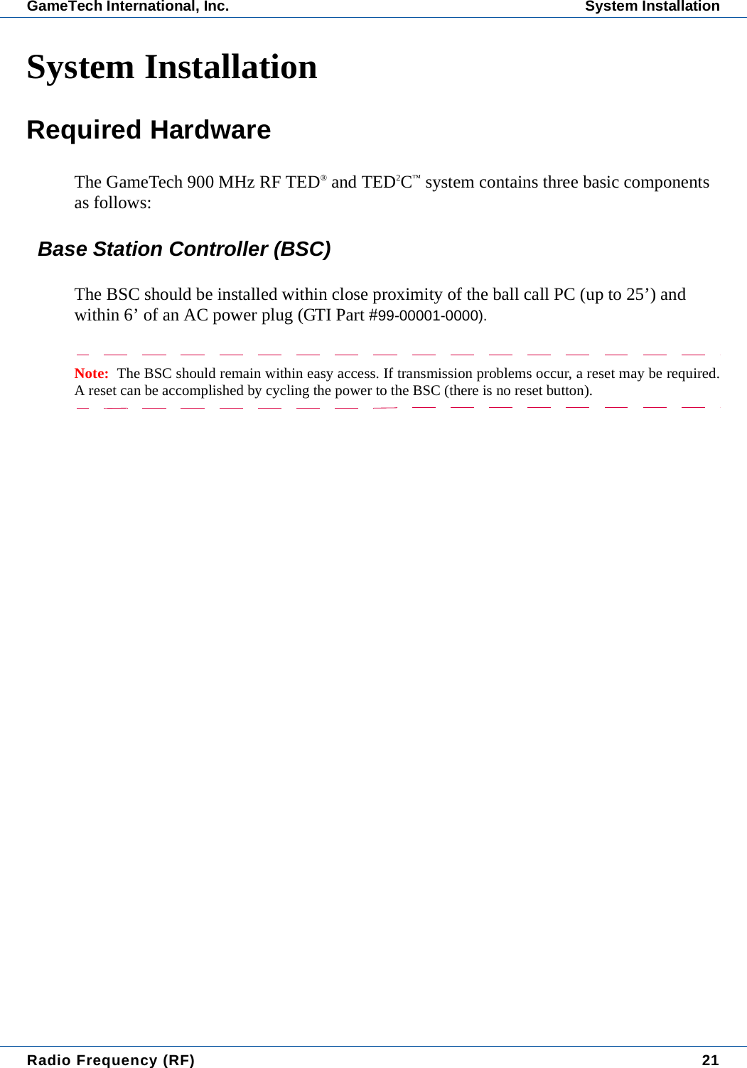
Gametech International One-Way Base Station Modem Unit Transmitter RF
UserManual.wiki
>
GameTech
>
300 00008 User Manual
User Manual
Navigation menu
Upload a User Manual
Namespaces
Wiki Guide
HTML
PDF
Info
Views
User Manual
Discussion / Help
Navigation


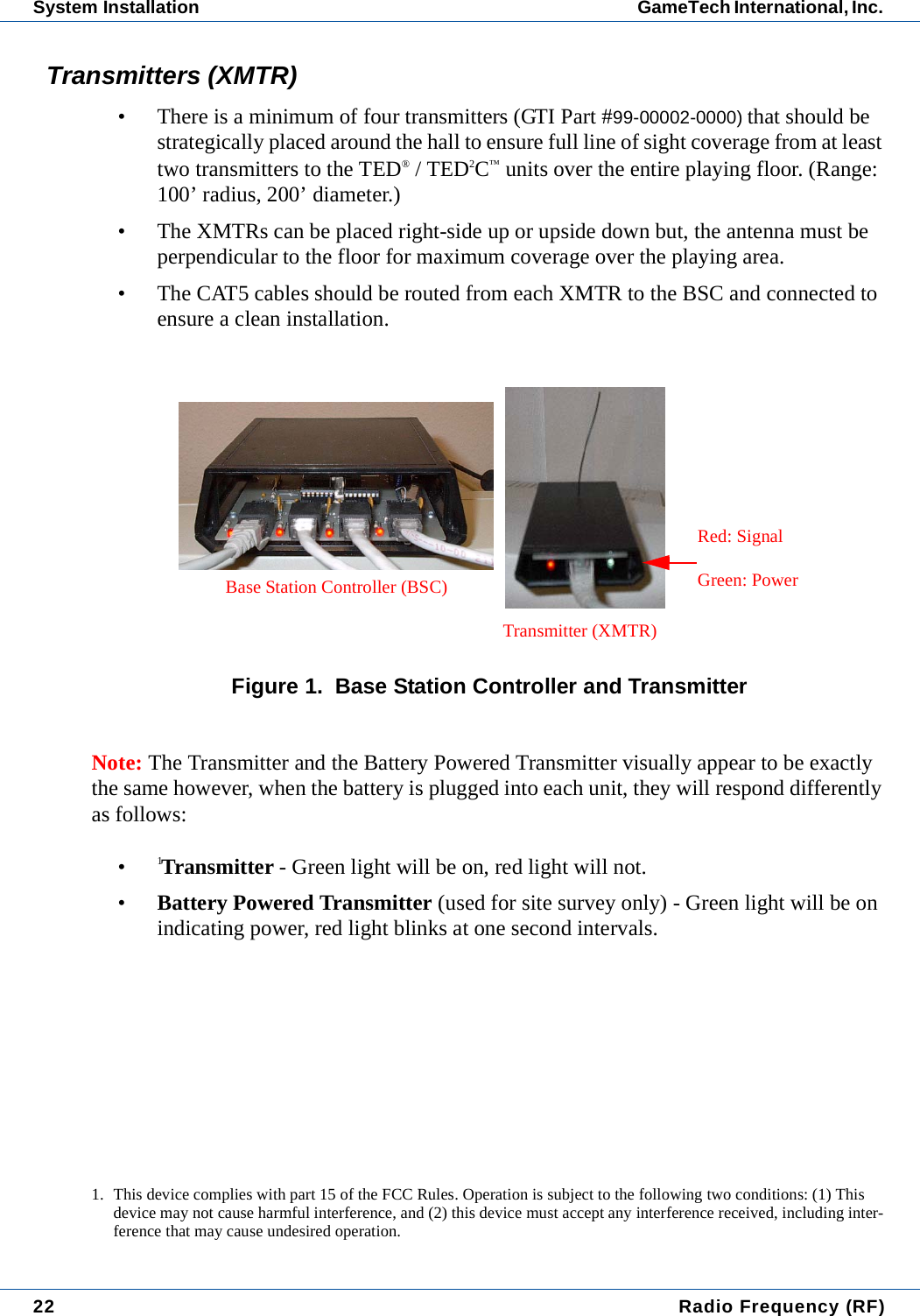
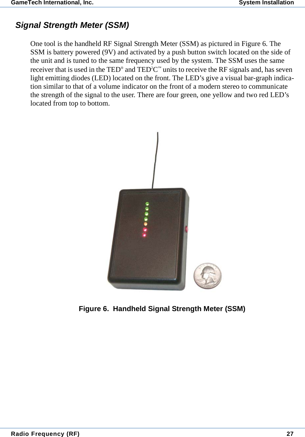
![Radio Frequency (RF) 31GameTech International, Inc. System InstallationCoverage• Position the standalone battery-powered transmitters in locations determined by the paper survey.• The SSM is then used to determine the adequacy of coverage of the transmitter placement.• With the system active at least one green LED should illuminate in all locations within the circle defined by the paper survey. Remember with one transmitter only, you may see the "dead spots" from location to location as you move through the area. This is normal. The SSM's receiver is calibrated to respond like those in the TED® and TED2C™.• One green LED illuminated is sufficient signal for essentially error free data transmission. When the entire system is installed it's expected for the top green LEDs to blink during normal system operation. Each transmitter is turned on sequentially by the BSC. No two transmitters are ever on at the same time. Consequently, the signal strength indicated by the green LEDs will vary caus-ing the top LEDs to blink on and off at the scan rate of the system. This phe-nomenon is caused by the SSM picking up transmitters close by (large signal) and those farther away (small signal).• If the signal strength, as indicated by the SSM, is adequate throughout the hall, the hall can be considered a good candidate for the RF system.CHH.INI SettingsMake the following changes to the [GENERAL] section of the CHH.INI: (\CHH directory)USE_RF=1.................................................... This setting should always be one.MASTER.INI SettingsMake the following changes to the [GENERAL] section of the MASTER.INI:(\TXT directory)RFENABLED=0.........................0=Off or 1, 2, 3 or 4 for appropriate com port.Note: When RF is enabled, the pick game option on the caller screen is disabled.](https://usermanual.wiki/GameTech/300-00008/User-Guide-442905-Page-39.png)
![32 Radio Frequency (RF)System Installation GameTech International, Inc. POS.INI SettingsIn Diamond POS v6.8.1 or later, sets the auto-daubing RF mode that the TED® and/or TED2C™ unit will use. In the POS.INI file, [GENERAL] section, set the UNIT_RFMODE=X where x=:UNIT_RFMODE=X1=Auto (Default mode)2=UNIT_RFMODE 23=UNIT_RFMODE 34=UNIT_RFMODE 40=Game Change OnlyNote: If the RF signal is lost, the unit will enter manual mode regardless of this setting.RFMODELOCKIn addition, in Diamond POS v6.8.1, the system can be further configured to allow or disal-low a player to switch to manual mode from the UNIT_RFMODE=X designated above. The player simply accesses the Lucky Options menu (TED2C™) or the Flashboard option (TED®). (This option is not available if the UNIT_RFMODELOCK=1.)UNIT_RFMODELOCK=00=(Default) Allows the player to switch to manual mode.1=Does not allow the player to switch to manual mode.For the TED® and TED2C™ units, download the following files (or later) to all RF-enabled units using the Program All function in Manager Functions. The POS will also need to be rebooted for these settings to take effect.CHH.EXE (9/20/03)TED325.BIN (9/20/03)Note: It is recommended that these settings not be changed during a session.](https://usermanual.wiki/GameTech/300-00008/User-Guide-442905-Page-40.png)