Garmin 02087 Class B AIS Transponder User Manual
Garmin International Inc Class B AIS Transponder
Garmin >
Contents
- 1. ais800_install
- 2. AIS800_ISPI
ais800_install
AIS 800
INSTALLATION
INSTRUCTIONS
Important Safety Information
WARNING
See the Important Safety and Product Information guide in the product box for
product warnings and other important information.
CAUTION
Always wear safety goggles, ear protection, and a dust mask when drilling,
cutting, or sanding.
NOTICE
When drilling or cutting, always check what is on the opposite side of the
surface.
Registering Your Device
Help us better support you by completing our online registration today. Keep
the original sales receipt, or a photocopy, in a safe place.
1Go to my.garmin.com/registration.
2Sign in to your Garmin® account.
FCC Compliance
NOTICE
In the USA, it is prohibited under FCC regulations to enter incorrect or
improper data, and it is prohibited for any person other than the manufacturer
or the installing dealer to input MMSI number.
It is a violation of the rules of the FCC to input an MMSI number that has not
been properly assigned to the user, or to otherwise input any inaccurate data
in this device.
Assigning Data to the Device
You must program the AIS 800 device with a valid vessel MMSI number
before installing the device on your boat. The device operates in silent mode
without a valid MMSI number. In silent mode, the device receives AIS signals,
but does not transmit position data. You can program the device to transmit
static vessel data including the vessel name, call sign, type, and dimensions,
which can include the location of your boat's GPS antenna.
Installing the AIS 800 Software on Your Computer
1Go to www.garmin.com/AIS800, select Software, and download the .zip
file to your computer.
2Connect the included USB cable to your computer and the USB port on the
AIS 800 device.
3Double-click the .exe file, and follow the on-screen instructions.
Programming the AIS 800
Before the device can be used on a boat, it must be programmed with a
unique MMSI number and with additional vessel-specific static data. The
MMSI number must be programmed by an authorized marine electronics
dealer or installer.
Before you can program the device, you must install the AIS 800 software on
your computer (Installing the AIS 800 Software on Your Computer, page 1).
1In the program, select the Static data tab.
2In the Connection and Status window, select COM11 from the drop-down
list.
3Select Connect.
4Enter your ship name, call sign, dimensions, vessel type, and MMSI
number (Assigning an MMSI Number to the AIS 800, page 1).
5Select Save data to AIS 800.
NOTE: The data is lost if the AIS 800 device is turned off. You must select
Save data to AIS 800 to permanently save your data.
6Select File > Exit.
Assigning an MMSI Number to the AIS 800
1Launch the AIS 800 setup software.
2In the Connection and Status window, select COM11 from the drop-down
list.
3Select Connect.
4In the Static Data window, enter your nine-digit MMSI number in the MMSI
Number field.
NOTICE
You cannot change the MMSI number after you assign the MMSI number
to your boat. If you assign an incorrect MMSI number, you must return the
device to the manufacturer for a factory reset.
5Select Save data to AIS 800.
Tools Needed
• Drill
• Drill bits appropriate for the surface and hardware
• Phillips screwdriver
• Pencil
Mounting Considerations
NOTICE
This device should be mounted in a location that is not exposed to extreme
temperatures or conditions. The temperature range for this device is listed in
the product specifications. Extended exposure to temperatures exceeding the
specified temperature range, in storage or operating conditions, may cause
device failure. Extreme-temperature-induced damage and related
consequences are not covered by the warranty.
• You must mount the device in a location where it will not be submerged.
• You must mount the device in a location with adequate ventilation where it
will not be exposed to extreme temperatures.
• If possible, you should mount the device horizontally, with the top of the
device facing upward.
• If you must mount the device vertically, you should orient it so the
connectors do not point upward. This helps avoid potential water retention
around the connectors.
• If you mount the device in a boat with a metal hull, you must connect the
device to an external GPS antenna.
Antenna Mounting and EME Exposure
WARNING
Radio operators with cardiac pacemakers, life-support machines, or electrical
medical equipment should not be exposed to excessive radio-frequency (RF)
fields, because the RF field may interfere with the function of their medical
equipment.
CAUTION
This device generates and radiates radio frequency (RF) electromagnetic
energy (EME). Failure to observe these guidelines may expose people to RF
radiation absorption exceeding the maximum permissible exposure (MPE).
Garmin declares a MPE radius of 2.48 m (97.64 in.) for this system, which was
determined using 5 W output to an omni-directional, 6 dBi gain antenna. The
antenna should be installed to maintain a distance of 2.48 m (97.64 in.)
between the antenna and all people.
Mounting the Device
NOTICE
If you are mounting the device in fiberglass, when drilling the pilot holes, it is
recommended to use a countersink bit to drill a clearance counterbore through
Printed in Germany
May 2018
190-02422-91_0B
only the top gel-coat layer. This will help to avoid cracking in the gel-coat layer
when the screws are tightened.
Before you mount the device, you must select a mounting location and
determine the mounting hardware needed for the surface.
NOTE: Mounting hardware is included with the device, but it may not be
suitable for the mounting surface.
1Place the device in the mounting location and mark the location of the pilot
holes.
2Using a bit appropriate for the surface and the mounting hardware, drill a
pilot hole for one corner of the device.
3Loosely fasten the device to the surface with one corner and examine the
other three pilot-hole marks.
4Mark new pilot-hole locations if necessary.
5Remove the device from the mounting surface.
6Drill the appropriate pilot holes for the other three marks.
7Secure the device to the mounting location.
Connection Considerations
Connecting the Wiring Harness to Power
1Route the wiring harness to the power source and to the device.
2Connect the red wire to the positive (+) battery terminal, and connect the
black wire to the negative (-) battery terminal.
Connecting a VHF Antenna
1Mount the VHF antenna (sold separately) according to the installation
instructions provided with the antenna.
NOTE: You can purchase a VHF extension cable. Go to buy.garmin.com
or contact your Garmin dealer.
2Connect the VHF antenna to the VHF ANT port on the AIS 800 device.
Connecting the Device to a Remote GPS Antenna
This device must receive GPS information for proper functionality. The device
includes an internal GPS antenna. If your mounting location does not provide
good GPS reception, you can install a remote GPS antenna (not included) and
connect it to the device.
1Follow the instructions provided with your external GPS antenna to install it
on your boat correctly.
2Route the GPSantenna cable to the back of your device, away from
sources of electrical interference.
3Connect the GPS antenna cable to the GPS ANT port on your device.
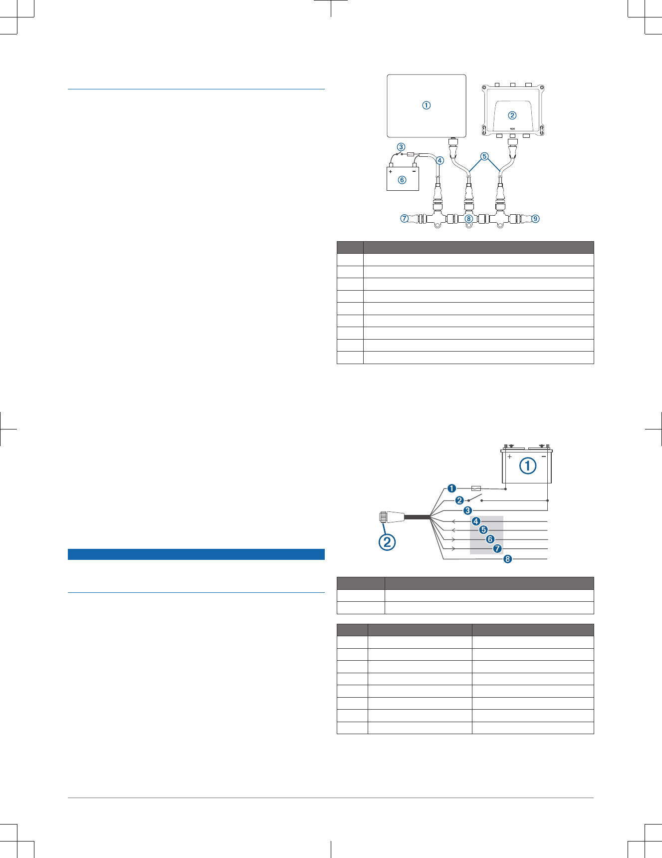
NMEA 2000® Device Connections
NOTICE
If you are installing a NMEA 2000 power cable, you must connect it to the boat
ignition switch or through another in-line switch. NMEA 2000 devices will drain
your battery if the NMEA 2000 power cable is connected to the battery directly.
If you are unfamiliar with NMEA 2000, you should read the “NMEA 2000
Network Fundamentals” chapter of the Technical Reference for NMEA 2000
Products. Go to www.garmin.com/manuals.
Item Description
ÀCompatible NMEA 2000 chartplotter or other device
ÁAIS 800 device
ÂIgnition or in-line switch
ÃNMEA 2000 power cable
ÄNMEA 2000 drop cable
Å12 Vdc power source
ÆNMEA 2000 terminator or backbone cable
ÇNMEA 2000 T-connector
ÈNMEA 2000 terminator or backbone cable
NMEA® 0183 Device Connections
This diagram illustrates two-way connections for both sending and receiving
data. You can also use this diagram for one-way communication. To receive
information from a NMEA 0183 device, refer to items Í, Î, and Ñ when
connecting the Garmin device. To transmit information to a NMEA 0183
device, refer to items Ï and Ð when connecting the Garmin device.
Item Description
ÀPower source
ÁPower/NMEA 0183 cable
Wire Garmin Wire Color Garmin Wire Function
ÊRed Power
ËYellow ACC on
ÌBlack Power ground
ÍPurple RxA (+)
ÎGray RxB (-)
ÏBlue TxA (+)
ÐBrown TxB (-)
ÑGreen Receive only
2

Appendix
Specifications
Dimensions (W x H x D) 175 x 142.3 x 54.5 mm (6.9 x 5.6 x 2.1 in.)
Weight 414 g (0.9 lbs.)
Operating temperature range From -15° to 55°C (from 5° to 131°F)
Storage temperature range From -20° to 75°C (from -4° to 167°F)
Water rating* IEC 605290 IPX7
Current draw 12 Vdc: < 400 mA
24 Vdc: < 250 mA
Power input 12 to 24 Vdc, 2 A max.
NMEA 2000 LEN 2
Transmit power 5 W (1 W remote switchable by authorities)
Antenna port impedence 50 ohm
Compass-safe distance 40 cm (15 3/4 in.)
**The device withstands incidental exposure to water of up to 1 m for up to
30 min. For more information, go to www.garmin.com/waterrating.
NMEA 2000 PGN Information
Type PGN Description
Receive 059392 ISO acknowledgment
059904 ISO request
060928 ISO address claim
126208 NMEA: Command, request,
acknowledge group
function
126992 System time
Transmit 059392 ISO acknowledgment
060928 ISO address claim
126208 NMEA: Command, request,
acknowledge group
function
126464 PGN list
126996 Product information
129038 AIS class A position report
129039 AIS class B position report
129040 AIS class B extended
position report
129041 AIS aids to navigation
(AtoN) report
129794 AIS class A static and
voyage related data
129795 AIS addressed binary
message
129797 AIS binary broadcast
message
129798 AIS SAR aircraft position
report
129802 AIS safety related
broadcast message
129809 AIS class B "CS" static data
report, part A
129810 AIS class B "CS" static data
report, part B
Status LEDs
LED State Description
VHF TX Solid A connected VHF radio is transmitting.
Error Flashing The device has encountered a critical error. You can
connect the device to a computer, and use the AIS 800
setup software to view detailed information about the
warning condition.
SRM Flashing The device is transmitting an SRM.
LED State Description
Warning Flashing The device detects a warning condition. You can connect
the device to a computer, and use the AIS 800 setup
software to view detailed information about the warning
condition.
RX Only Flashing The device is receiving an AIS message.
TX Flashing The device is sending an AIS message.
RX Solid The device is in silent mode or not ready to transmit.
NOTE: The AIS 800 device does not transmit without a GPS
signal or an MMSI number, when the AIS base station
commands a quiet time, or when the device encounters a
critical error.
Power Solid The device is ready to transmit and receive.
VHF TX, Error,
Warning, and
Power.
Solid The device is connected only to a USB cable.
© 2018 Garmin Ltd. or its subsidiaries
Garmin® and the Garmin logo are trademarks of Garmin Ltd. or its subsidiaries,
registered in the USA and other countries. These trademarks may not be used without
the express permission of Garmin.
NMEA®, NMEA 2000®, and the NMEA 2000 logo are registered trademarks of the
National Marine Electronics Association.
3

support.garmin.com