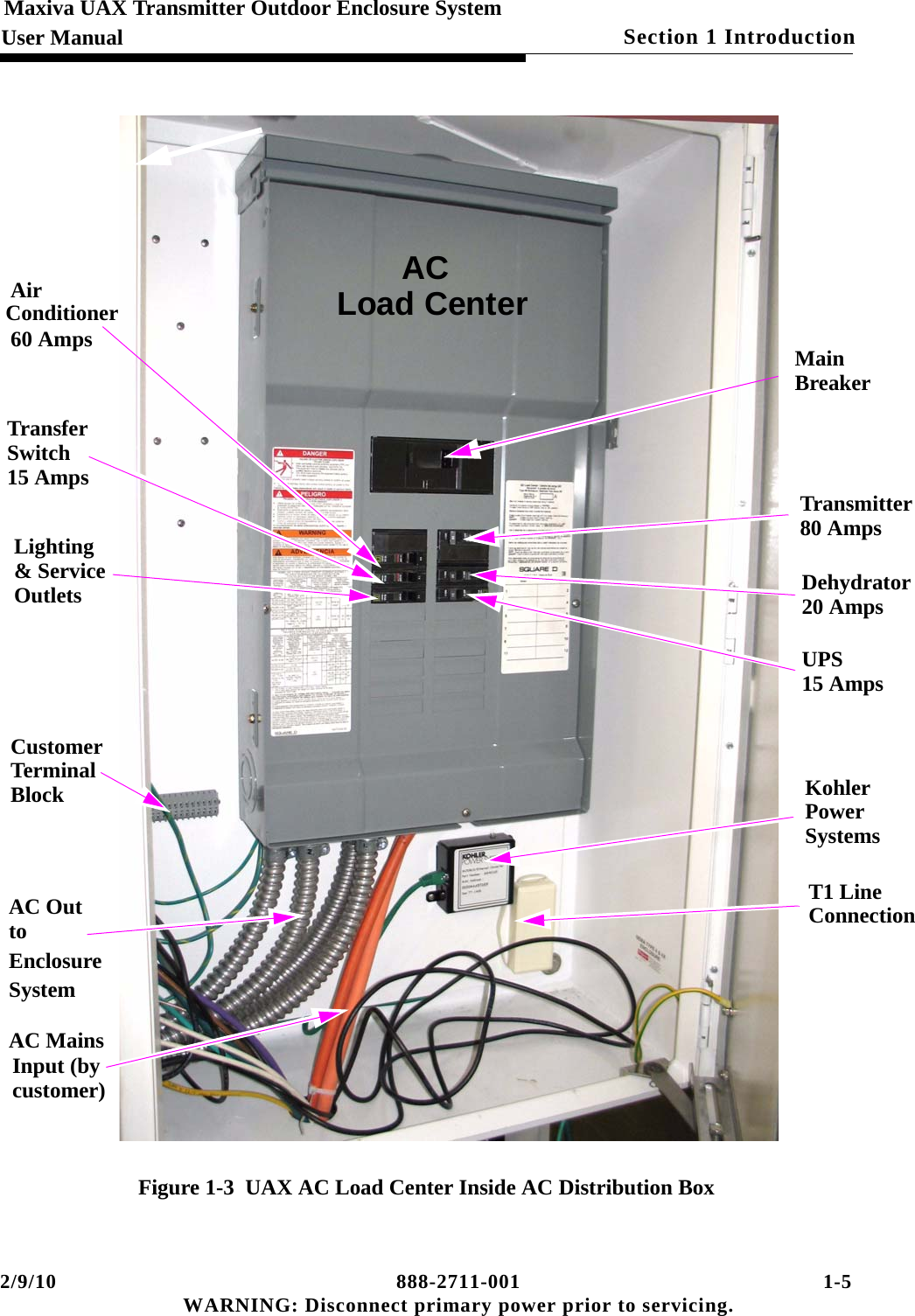
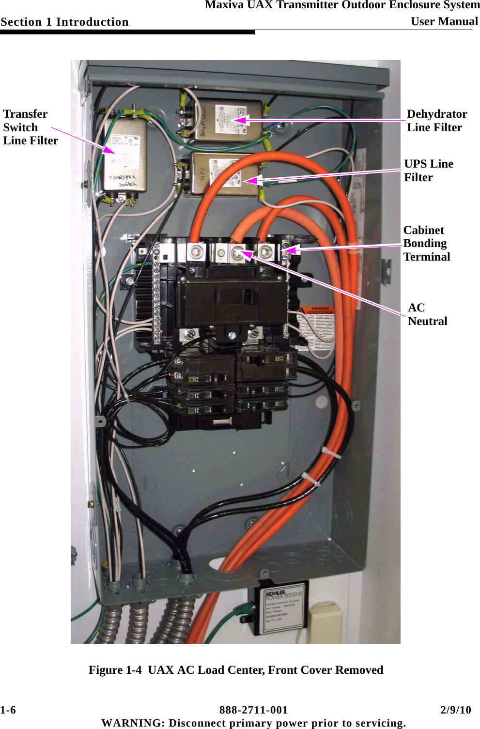
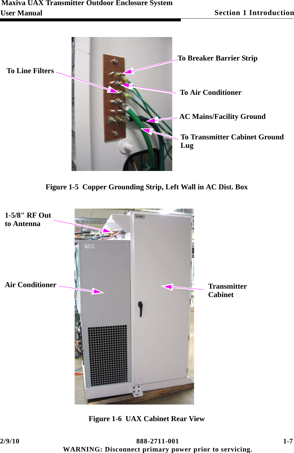
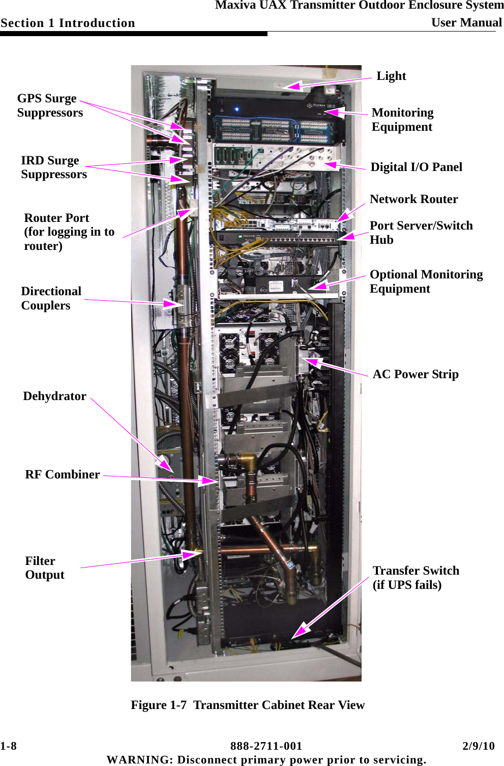
GatesAir UAXDVF Maxiva UAX Outdoor Transmitter User Manual 2711
GatesAir, Inc. Maxiva UAX Outdoor Transmitter 2711
UserManual.wiki
>
GatesAir
>
UAXDVF User Manual
User Manual
Navigation menu
Upload a User Manual
Namespaces
Wiki Guide
HTML
PDF
Info
Views
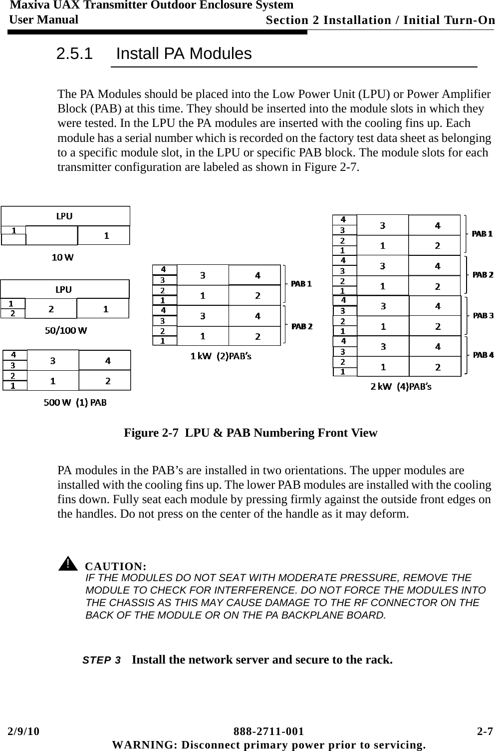
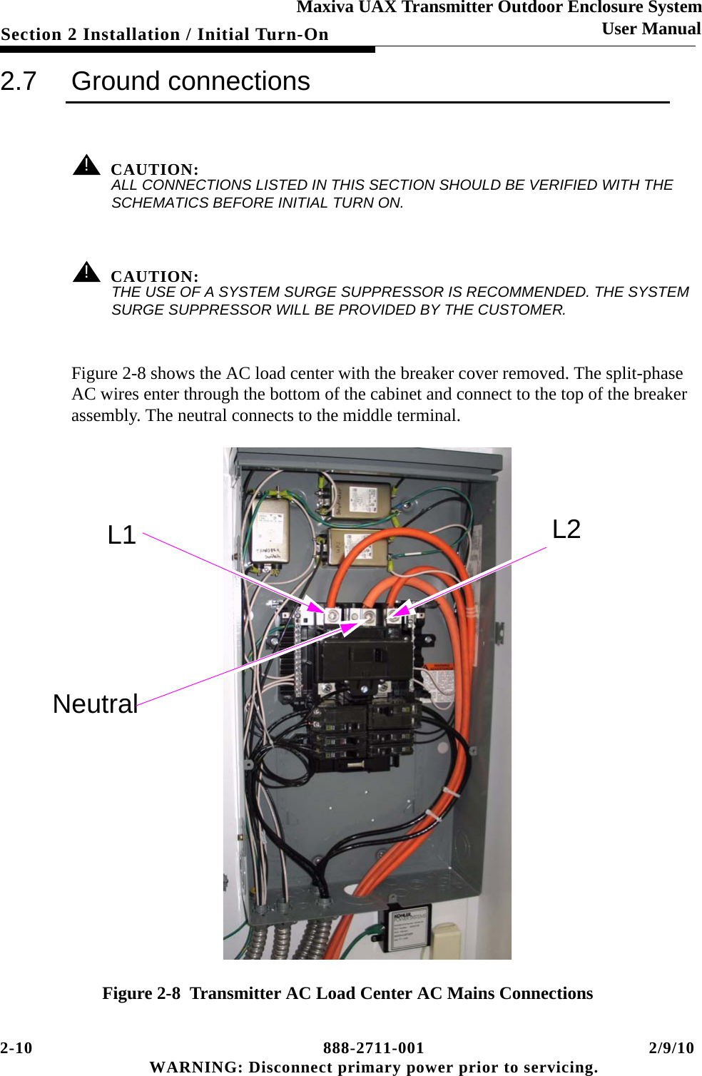
User Manual
Discussion / Help
Navigation