GatesAir UAXDVF Maxiva UAX Outdoor Transmitter User Manual 2711
GatesAir, Inc. Maxiva UAX Outdoor Transmitter 2711
GatesAir >
User Manual

Maxiva UAX Transmitter
Outdoor Enclosure System
888-2711-001
Maxiva UAX Transmitter
Outdoor Enclosure System
User Manual
Feb. 9, 2010
Rev: A
T.M. No. 888-2711-001
© Copyright Harris Corporation 2010
All rights reserved

ii 888-2711-001 2/9/10
WARNING: Disconnect primary power prior to servicing.

2/9/10 888-2711-001 iii
WARNING: Disconnect primary power prior to servicing.
Technical Assistance
Technical and troubleshooting assistance for HARRIS Transmission products is available from
HARRIS Field Service (factory location: Quincy, Illinois, USA) during normal business hours
(8:00 AM - 5:00 PM Central Time). Telephone +1-217-222-8200 to contact the Field Service
Department; FAX +1-217-221-7086; or E-mail questions to tsupport@harris.com.
Emergency service is available 24 hours a day, seven days a week, by telephone only.
On-line assistance, including technical manuals, white papers, software downloads, and service
bulletins, is available at http://support.broadcast.harris.com/eservice_enu.
Address written correspondence to Field Service Department, HARRIS Broadcast
Communications Division, P.O. Box 4290, Quincy, Illinois 62305-4290, USA. For other global
service contact information, please visit: http://www.broadcast.harris.com/contact.
NOTE: For all service and parts correspondence, you will need to provide the Sales Order
number, as well as the Serial Number for the transmitter or part in question. For future reference,
record those numbers here: ___________________/____________________
Please provide these numbers for any written request, or have these numbers ready in the event
you choose to call regarding any Service, or Parts requests. For warranty claims it will be required,
and for out of warranty products, this will help us to best identify what specific hardware was
shipped.
Replaceable Parts Service
Replacement parts are available from HARRIS Service Parts Department from 7:00 AM to 11:00
PM Central Time, seven days a week. Telephone +1-217-222-8200 or email
servicepartsreq@harris.com to contact the Service Parts Department.
Emergency replacement parts are available by telephone only, 24 hours a day, seven days a
week by calling +1-217-222-8200.
Unpacking
Carefully unpack the equipment and preform a visual inspection to determine if any apparent
damage was incurred during shipment. Retain the shipping materials until it has been verified that
all equipment has been received undamaged. Locate and retain all PACKING CHECK LISTs. Use
the PACKING CHECK LIST to help locate and identify any components or assemblies which are
removed for shipping and must be reinstalled. Also remove any shipping supports, straps, and
packing materials prior to initial turn on.
Returns And Exchanges
No equipment can be returned unless written approval and a Return Authorization is received from
HARRIS Broadcast Communications Division. Special shipping instructions and coding will be
provided to assure proper handling. Complete details regarding circumstances and reasons for
return are to be included in the request for return. Custom equipment or special order equipment is
not returnable. In those instances where return or exchange of equipment is at the request of the
customer, or convenience of the customer, a restocking fee will be charged. All returns will be sent
freight prepaid and properly insured by the customer. When communicating with HARRIS
Broadcast Communications Division, specify the HARRIS Order Number or Invoice Number.

iv 888-2711-001 2/9/10
WARNING: Disconnect primary power prior to servicing.

2/9/10 888-2711-001 MRH-1
WARNING: Disconnect primary power prior to servicing.
Manual Revision History
Maxiva UAX Transmitter Outdoor Enclosure System Manual
REV. DATE ECN Pages Affected / Description
2010 FEB Create manual.

MRH-2 888-2711-001 2/9/10
WARNING: Disconnect primary power prior to servicing.
2/9/10 888-2711-001 vii
WARNING: Disconnect primary power prior to servicing.
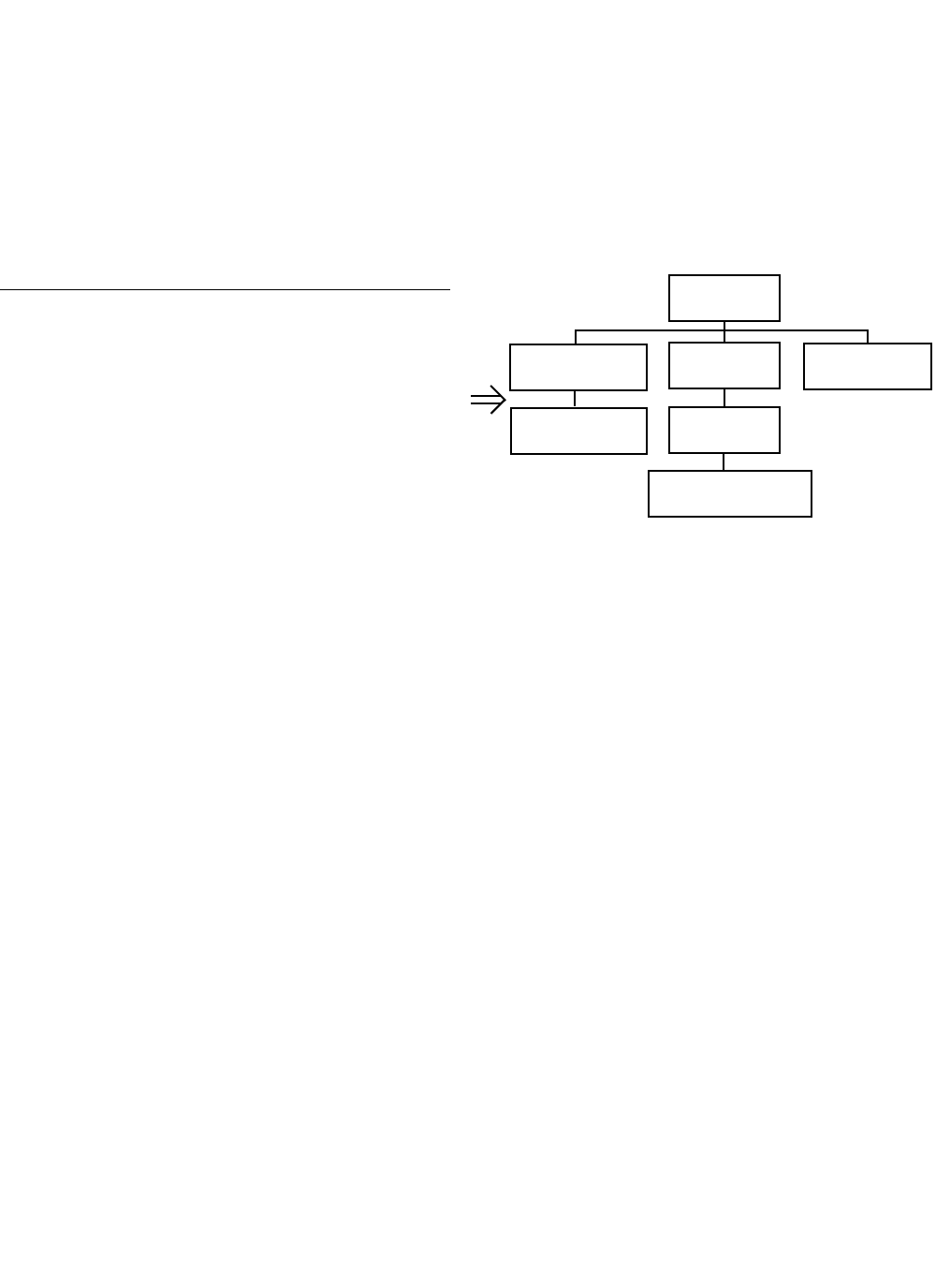
Guide to Using Harris Parts List Information
The Harris Replaceable Parts List Index portrays a tree structure with the major items being leftmost in the index.
The example below shows the Transmitter as the highest item in the tree structure. If you were to look at the bill
of materials table for the Transmitter you would find the Control Cabinet, the PA Cabinet, and the Output
Cabinet. In the Replaceable Parts List Index the Control Cabinet, PA Cabinet, and Output Cabinet show up one
indentation level below the Transmitter and implies that they are used in the Transmitter. The Controller Board is
indented one level below the Control Cabinet so it will show up in the bill of material for the Control Cabinet.
The tree structure of this same index is shown to the right of the table and shows indentation level versus tree
structure level.
Example of Replaceable Parts List Index and equivalent tree structure:
Replaceable Parts List Index Part Number Page
Table 7-1. Transmitter 994 9283 001 7-2
Table 7-2. Control Cabinet 992 9244 002 7-3
Table 7-3. Controller Board 992 8344 002 7-6
Table 7-4. PA Cabinet 992 9400 002 7-7
Table 7-5. PA Amplifier 994 7894 002 7-9
Table 7-6. PA Amplifier Board 992 7904 002 7-10
Table 7-7. Output Cabinet 992 9450 001 7-12
The part number of the item is shown to the right of the description as is the page in the manual where the bill for
that part number starts. Inside the actual tables, four main headings are used:
•Table #-#. ITEM NAME - HARRIS PART NUMBER - this line gives the information that corresponds
to the
•Replaceable Parts List Index entry;
•HARRIS P/N column gives the ten digit Harris part number (usually in ascending order);
•DESCRIPTION column gives a 25 character or less description of the part number;
•REF. SYMBOLS/EXPLANATIONS column 1) gives the reference designators for the item (i.e., C001,
R102, etc.) that corresponds to the number found in the schematics (C001 in a bill of material is equiva-
lent to C1 on the schematic) or 2) gives added information or further explanation (i.e., “Used for 208V
operation only,” or “Used for HT 10LS only,” etc.).
NOTE: Inside the individual tables some standard conventions are used:
•A # symbol in front of a component such as #C001 under the REF. SYMBOLS/EXPLANATIONS col-
umn means that this item is used on or with C001 and is not the actual part number for C001.
•In the ten digit part numbers, if the last three numbers are 000, the item is a part that Harris has pur-
chased and has not manufactured or modified. If the last three numbers are other than 000, the item is
either manufactured by Harris or is purchased from a vendor and modified for use in the Harris product.
•The first three digits of the ten digit part number tell which family the part number belongs to - for
example, all electrolytic (can) capacitors will be in the same family (524 xxxx 000). If an electrolytic
(can) capacitor is found to have a 9xx xxxx xxx part number (a number outside of the normal family of
numbers), it has probably been modified in some manner at the Harris factory and will therefore show
up farther down into the individual parts list (because each table is normally sorted in ascending order).
Most Harris made or modified assemblies will have 9xx xxxx xxx numbers associated with them.
The term “SEE HIGHER LEVEL BILL” in the description column implies that the reference designated part
number will show up in a bill that is higher in the tree structure. This is often the case for components
that may be frequency determinant or voltage determinant and are called out in a higher level bill
structure that is more customer dependent than the bill at a lower level.
Transmitter
994 9283 001
Control Cabinet
992 9244 002
Controller Board
992 8344 002
PA Cabinet
992 9400 002
PA Amplifier
992 7894 002
PA Amplifier Board
992 7904 002
Output Cabinet
992 9450 001

viii 888-2711-001 2/9/10
WARNING: Disconnect primary power prior to servicing.
2/9/10 888-2711-001 ix
WARNING: Disconnect primary power prior to servicing.

x 888-2711-001 2/9/10
WARNING: Disconnect primary power prior to servicing.

2/9/10 888-2711-001 xi
WARNING: Disconnect primary power prior to servicing.
! WARNING:
THE CURRENTS AND VOLTAGES IN THIS EQUIPMENT ARE DANGEROUS.
PERSONNEL MUST AT ALL TIMES OBSERVE SAFETY WARNINGS, INSTRUC-
TIONS AND REGULATIONS.
This manual is intended as a general guide for trained and qualified personnel who are aware
of the dangers inherent in handling potentially hazardous electrical/electronic circuits. It is not
intended to contain a complete statement of all safety precautions which should be observed
by personnel in using this or other electronic equipment.
The installation, operation, maintenance and service of this equipment involves risks both to
personnel and equipment, and must be performed only by qualified personnel exercising due
care. HARRIS CORPORATION shall not be responsible for injury or damage resulting from
improper procedures or from the use of improperly trained or inexperienced personnel
performing such tasks. During installation and operation of this equipment, local building
codes and fire protection standards must be observed.
The following National Fire Protection Association (NFPA) standards are recommended as
reference:
- Automatic Fire Detectors, No. 72E
- Installation, Maintenance, and Use of Portable Fire Extinguishers, No. 10
- Halogenated Fire Extinguishing Agent Systems, No. 12A
! WARNING:
ALWAYS DISCONNECT POWER BEFORE OPENING COVERS, DOORS, ENCLO-
SURES, GATES, PANELS OR SHIELDS. ALWAYS USE GROUNDING STICKS
AND SHORT OUT HIGH VOLTAGE POINTS BEFORE SERVICING. NEVER MAKE
INTERNAL ADJUSTMENTS, PERFORM MAINTENANCE OR SERVICE WHEN
ALONE OR WHEN FATIGUED.
Do not remove, short-circuit or tamper with interlock switches on access covers, doors,
enclosures, gates, panels or shields. Keep away from live circuits, know your equipment and
don’t take chances.
! WARNING:
IN CASE OF EMERGENCY ENSURE THAT POWER HAS BEEN DISCONNECTED.
IF OIL FILLED OR ELECTROLYTIC CAPACITORS ARE UTILIZED IN YOUR
EQUIPMENT, AND IF A LEAK OR BULGE IS APPARENT ON THE CAPACITOR CASE
WHEN THE UNIT IS OPENED FOR SERVICE OR MAINTENANCE, ALLOW THE UNIT
TO COOL DOWN BEFORE ATTEMPTING TO REMOVE THE DEFECTIVE CAPACITOR.
DO NOT ATTEMPT TO SERVICE A DEFECTIVE CAPACITOR WHILE IT IS HOT DUE TO
THE POSSIBILITY OF A CASE RUPTURE AND SUBSEQUENT INJURY.
xii 888-2711-001 2/9/10
WARNING: Disconnect primary power prior to servicing.

2/9/10 888-2711-001 xiii
WARNING: Disconnect primary power prior to servicing.
FIRST-AID
Personnel engaged in the installation, operation, maintenance or servicing of this equipment
are urged to become familiar with first-aid theory and practices. The following information is
not intended to be complete first-aid procedures, it is a brief and is only to be used as a
reference. It is the duty of all personnel using the equipment to be prepared to give adequate
Emergency First Aid and there by prevent avoidable loss of life.
Treatment of Electrical Burns
1. Extensive burned and broken skin
a. Cover area with clean sheet or cloth. (Cleanest available cloth
article.)
b. Do not break blisters, remove tissue, remove adhered particles of
clothing, or apply any salve or ointment.
c. Treat victim for shock as required.
d. Arrange transportation to a hospital as quickly as possible.
e. If arms or legs are affected keep them elevated.
NOTE:
If medical help will not be available within an hour and the victim is conscious and
not vomiting, give him a weak solution of salt and soda: 1 level teaspoonful of salt
and 1/2 level teaspoonful of baking soda to each quart of water (neither hot or
cold). Allow victim to sip slowly about 4 ounces (a half of glass) over a period of
15 minutes. Discontinue fluid if vomiting occurs. (Do not give alcohol.)
2. Less severe burns - (1st & 2nd degree)
a. Apply cool (not ice cold) compresses using the cleanest available
cloth article.
b. Do not break blisters, remove tissue, remove adhered particles of
clothing, or apply salve or ointment.
c. Apply clean dry dressing if necessary.
d. Treat victim for shock as required.
e. Arrange transportation to a hospital as quickly as possible.
f. If arms or legs are affected keep them elevated.
REFERENCE:
ILLINOIS HEART ASSOCIATION
AMERICAN RED CROSS STANDARD FIRST AID AND PERSONAL SAFETY
MANUAL (SECOND EDITION)

xiv 888-2711-001 2/9/10
WARNING: Disconnect primary power prior to servicing.
Glossary:
ASI - Asynchronous serial interface
BPF- Band pass filter. May also be called a mask filter, or critical mask filer.
CAN - Controller–area network (CAN or CAN-bus) is a vehicle bus standard
designed to allow microcontrollers and devices to communicate with each other
DAC - digital analog converter
FPGA - Field programmable gate array
GUI - graphical user interface
Hot-pluggable - device can be removed while transmitter is operating.
HTML - HyperText Markup Language
IRD - Integrated receiver decoder
LCD - Liquid crystal display
LPF - Low pass filter. Typically located at the transmitter output port. Used to
attenuate out of band emissions.
LPU - Low power unit. Contains modulator and amplifier sections.
MCM - Master control module (card in TCU)
PA - Power amplifier
PAB - Power amplifier block
PCM - Processor control module (card in TCU)
PS - Power supply
RF - Radio frequency
RS-485 -TIA/EIA standard for serial multipoint communications lines
RTACTM - Real time adaptive correction

2/9/10 888-2711-001 xv
WARNING: Disconnect primary power prior to servicing.
Glossary Continued:
SFN - Single frequency network
SMA - SMA connector consists of a 0.250x36 thread. The male is equipped with a
.312 inch (7.925mm) hex nut
TCU - Transmitter control unit.
UDC - Up-down converter
UPS - Uninterruptable power supply
VGA - Video graphics array
WEB - A system of Internet servers that support HTML formatted documents.

xvi 888-2711-001 2/9/10
WARNING: Disconnect primary power prior to servicing.

Table of Contents
1
Section 1
Introduction
Purpose of This Manual . . . . . . . . . . . . . . . . . . . . 1-1
General Description. . . . . . . . . . . . . . . . . . . . . . . . 1-3
System Block Diagrams . . . . . . . . . . . . . . . . . . . 1-11
System Specifications . . . . . . . . . . . . . . . . . . . . . 1-12
Environmental and Physical. . . . . . . . . . . . . . . 1-12
AC power . . . . . . . . . . . . . . . . . . . . . . . . . . . . . 1-12
Connectors . . . . . . . . . . . . . . . . . . . . . . . . . . . . 1-12
Section 2
Installation /
Initial Turn-On
Introduction. . . . . . . . . . . . . . . . . . . . . . . . . . . . . . 2-1
Documentation . . . . . . . . . . . . . . . . . . . . . . . . . . . 2-1
UAX Enclosure System Drawings . . . . . . . . . . . 2-2
Cabinet Placement. . . . . . . . . . . . . . . . . . . . . . . . . 2-2
Cabinet Attachments . . . . . . . . . . . . . . . . . . . . . . . 2-4
Installation of Components Removed for Shipment2-6
Install PA Modules . . . . . . . . . . . . . . . . . . . . . . . 2-7
AC/Ground connections . . . . . . . . . . . . . . . . . . . . 2-9
Ground connections. . . . . . . . . . . . . . . . . . . . . . . 2-10
Transmitter RF output connection. . . . . . . . . . . . 2-12
Signal Connections . . . . . . . . . . . . . . . . . . . . . . . 2-14
Customer Remote Control & Interlock
Connections. . . . . . . . . . . . . . . . . . . . . . . . . . . . . 2-15
Customer Remote Control & Interlock
Connections. . . . . . . . . . . . . . . . . . . . . . . . . . . . . 2-16
Initial Turn-On . . . . . . . . . . . . . . . . . . . . . . . . . . 2-16
Section 3
Operation & Maintenance
Introduction. . . . . . . . . . . . . . . . . . . . . . . . . . . . . . 3-1
Transmitter Control Unit (TCU) . . . . . . . . . . . . . . 3-1
Control Buttons overview: . . . . . . . . . . . . . . . . . 3-2
Maintenance . . . . . . . . . . . . . . . . . . . . . . . . . . . . . 3-4
Section 4
Parts List
Replaceable Parts List. . . . . . . . . . . . . . . . . . . . . . 4-1

Table of Contents
2

2/9/10 888-2711-001 1-1
WARNING: Disconnect primary power prior to servicing.
Maxiva UAX Transmitter Outdoor Enclosure System
User Manual
Section 1
Introduction 1
1.1 Purpose of This Manual
This User manual describes the UAX Outdoor Enclosure System utilizing the UAX
Maxiva transmitter. The contents of this manual address the location of system
components of the enclosure system, installation hook-up requirements, initial turn-on
steps, and overall system operation. Detailed information pertaining to the UAX
Maxiva Transmitter is not included here, but can be found in a separate doc package
(988-2693-001) included with the transmitter. Detailed information regarding
individual system components can be found in the component documentation material
supplied with this enclosure system. The various sections of this User manual provide
the following types of information.
Section 1, Introduction, provides equipment location information, block diagram and
general specifications.
Section 2, Installation/Initial Turn-On, provides cabinet hardware and electrical
installation information for the transmitter enclosure system including: Cabinet
placement, solar shield, GPS antenna, AC Power connection, RF system connections,
customer input connections, and remote interface connections.
Section 3, Operation, provides general operation information for the enclosure system.
Specific equipment operation information can be found in the technical manuals/
pamphlets provided by the manufactures of the various components included in the
enclosure system. Most of these can be found in a pouch inside the back door of the
enclosure.
Section 4, Parts List, provides a list of parts used in a typical UAX enclosure system.
1-2 888-2711-001 2/9/10
WARNING: Disconnect primary power prior to servicing.
Section 1 Introduction User Manual
Maxiva UAX Transmitter Outdoor Enclosure System
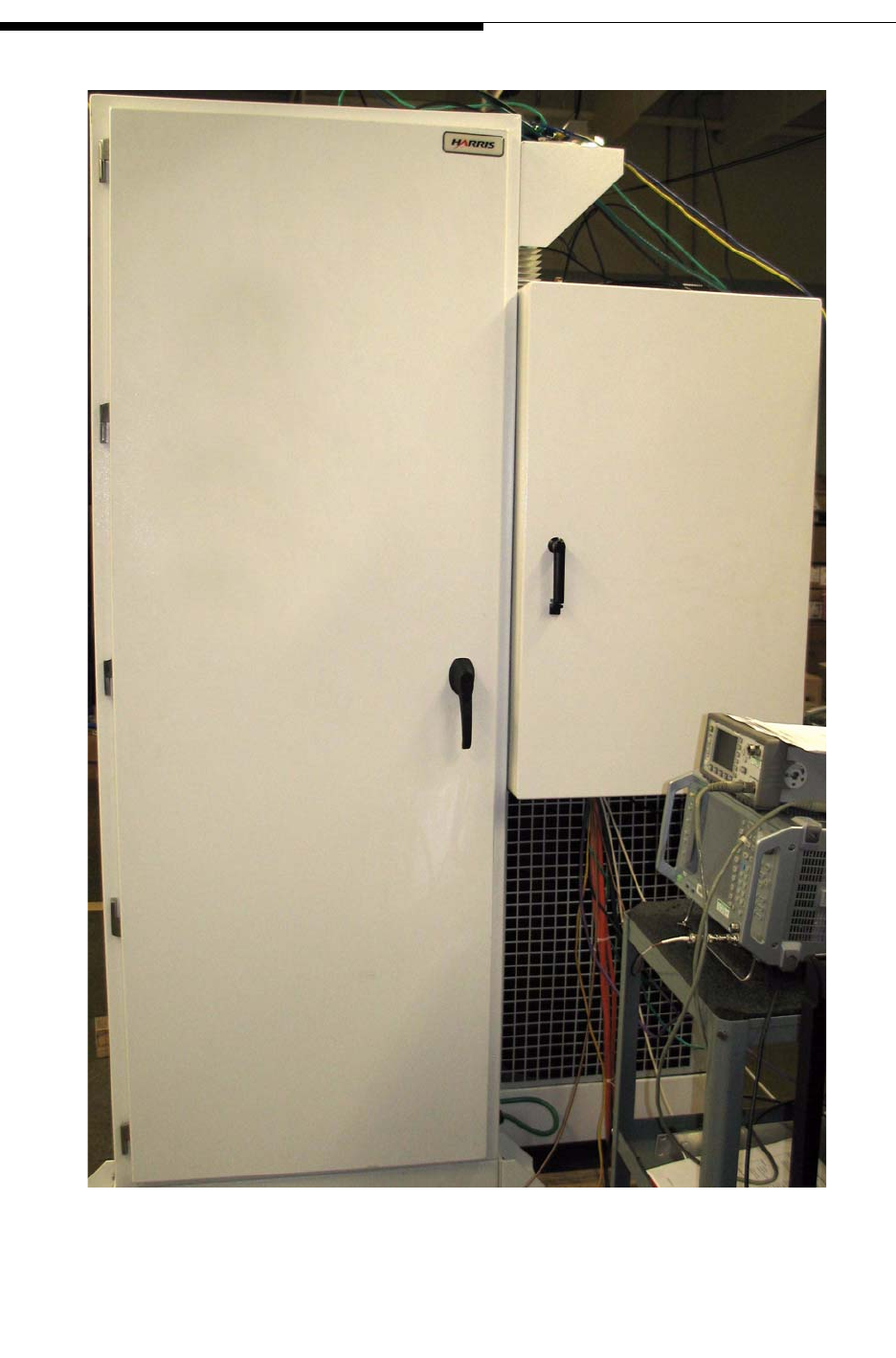
Figure 1-1 UAX Outdoor Enclosure System - Front Doors
Main Equipment
Cabinet AC Distribution
Box

2/9/10 888-2711-001 1-3
WARNING: Disconnect primary power prior to servicing.
Section 1 Introduction
Maxiva UAX Transmitter Outdoor Enclosure System
User Manual
1.2 General Description
This section contains equipment/hardware location information of the UAX Enclosure
System. Included in this section will be photos of the various components, physical
location, interconnection, block diagram and system specifications.
The UAX Outdoor Enclosure System is a self contained transmission system designed
to be installed in outdoor environments without the need of a shelter. The system
includes the Harris solid state UAX Transmitter, an on-board system air conditioning
system, and an on-board AC Power Distribution Box.
There are three models system models:
•UAX2000FLS Outdoor System -2Kw RF Power Level with Single Exciter
•UAX2000FLD Outdoor System - 2Kw RF Power Level with Dual Exciters and
Transmitter Control Unit
•UAX1000FLS Outdoor System- 1Kw RF Power Level with Single Exciter.
The transmitter cabinets utilize a rack mount system that accommodates additional
peripheral equipment including a UPS unit, mask filter, router, port server, monitoring
unit, and customer supplied satellite receivers, IRDs, etc.
The self-contained system requires a stable/secure installation pad and external
connections. The external connections include:
1. Proper grounding
2. AC Mains
! WARNING:
INSTALLATION OF THE AC MAINS AND GROUNDING MUST BE PERFORMED IN
ACCORDANCE WITH ALL APPLICABLE CODES.
3. Antenna coax
4. Customer data stream input
5. Remote control/monitoring
Figure 1-2 shows the front of the enclosure system with the door open.
1-4 888-2711-001 2/9/10
WARNING: Disconnect primary power prior to servicing.
Section 1 Introduction User Manual
Maxiva UAX Transmitter Outdoor Enclosure System
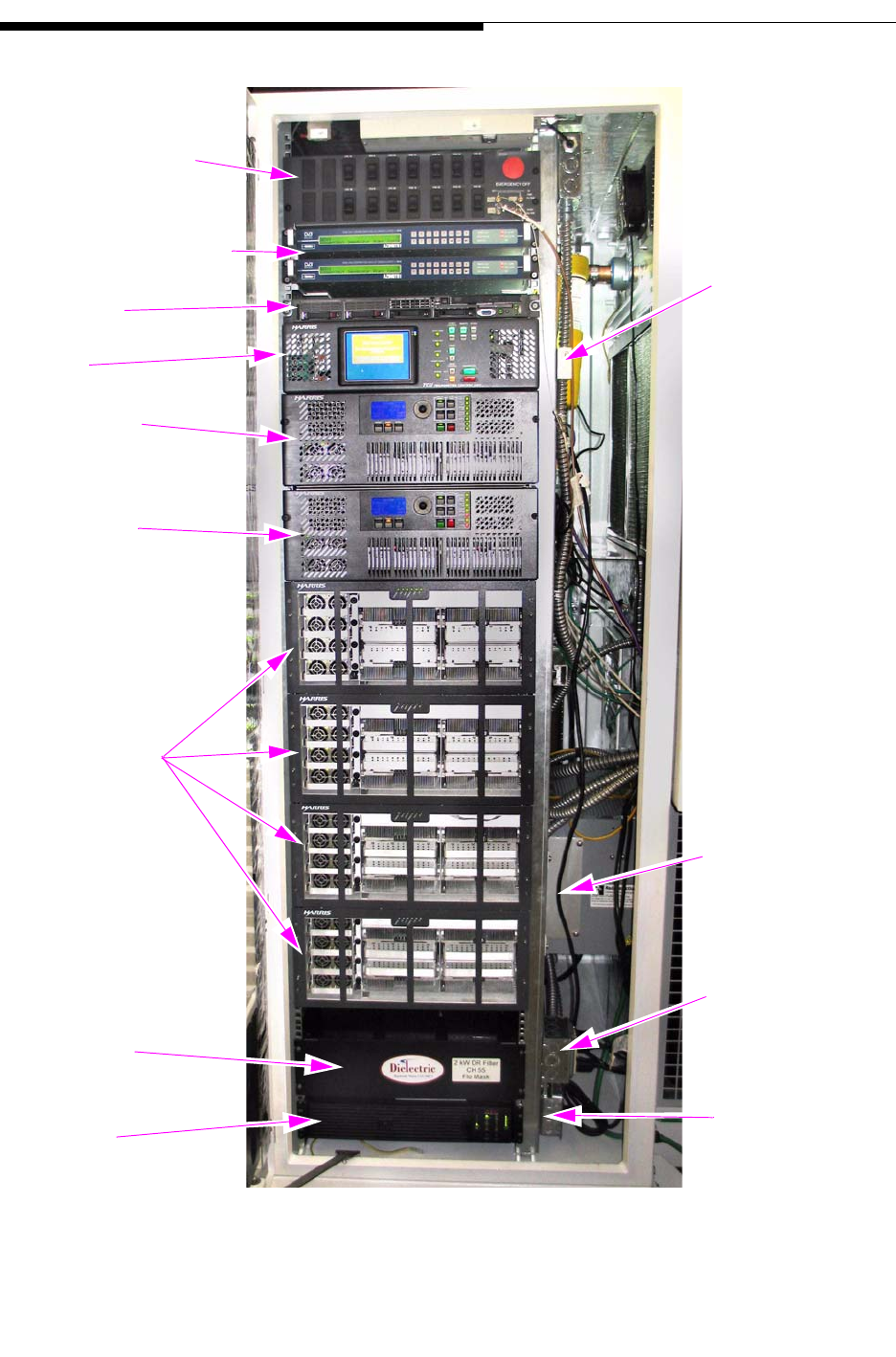
Figure 1-2 UAX Transmitter - Front View
AC Distribution
Panel
Ethernet Port
Sat. Receiver & IRD
Network
TCU
LPU A
LPU B
Transmitter
Power
Amplifiers
2 kW
Mask
Filter
UPS
Radio Detection
Dehydrator
AC Service
Outlets with
GFI Protection
Single Outlet
for Dehydrator
Transmitter
PAB 1-4
Server
2/9/10 888-2711-001 1-5
WARNING: Disconnect primary power prior to servicing.
Section 1 Introduction
Maxiva UAX Transmitter Outdoor Enclosure System
User Manual
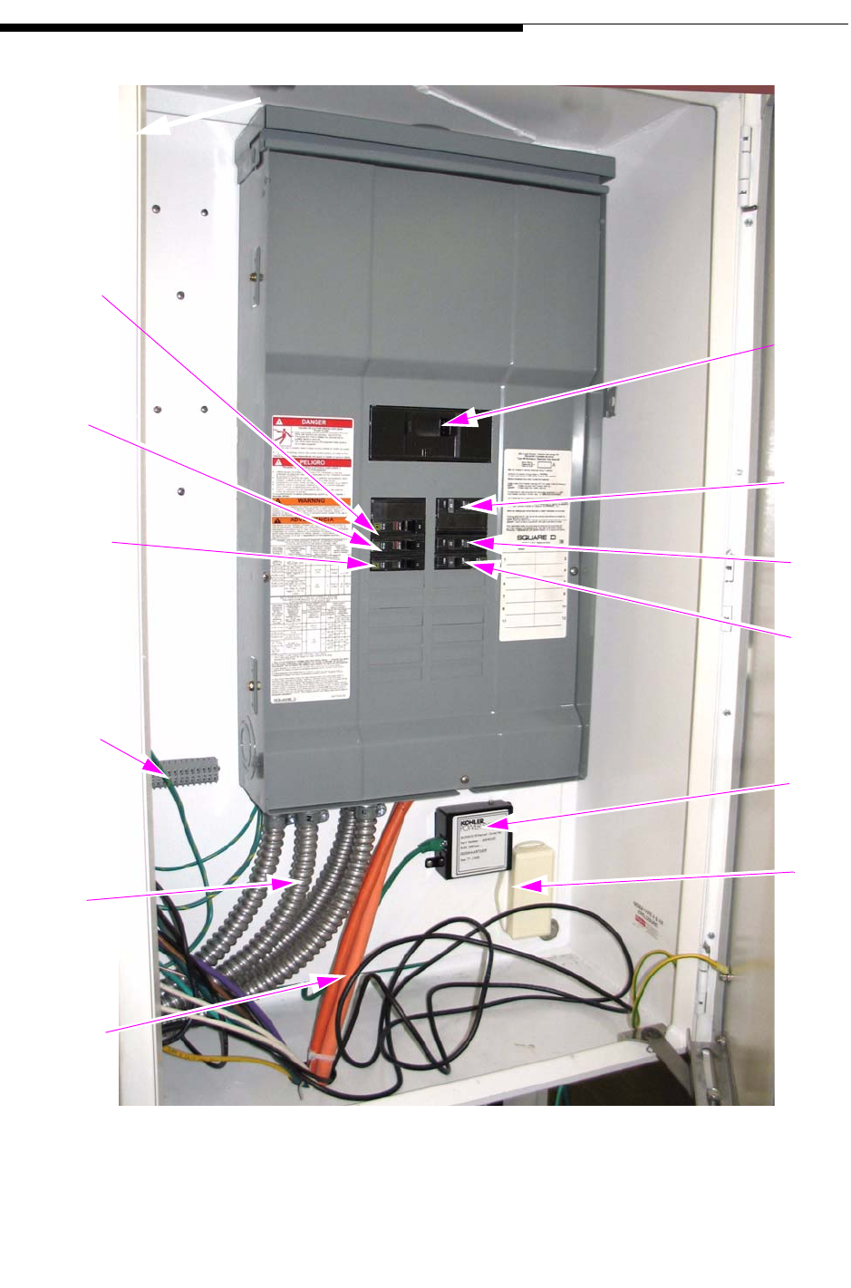
Figure 1-3 UAX AC Load Center Inside AC Distribution Box
Main
Breaker
Transmitter
80 Amps
Dehydrator
20 Amps
UPS
15 Amps
Kohler
Power
Systems
T1 Line
Connection
Air
Conditioner
60 Amps
Transfer
Switch
15 Amps
Lighting
& Service
Outlets
Customer
Terminal
Block
AC Out
to
System
Enclosure
AC Mains
Input (by
customer)
AC
Load Center
1-6 888-2711-001 2/9/10
WARNING: Disconnect primary power prior to servicing.
Section 1 Introduction User Manual
Maxiva UAX Transmitter Outdoor Enclosure System
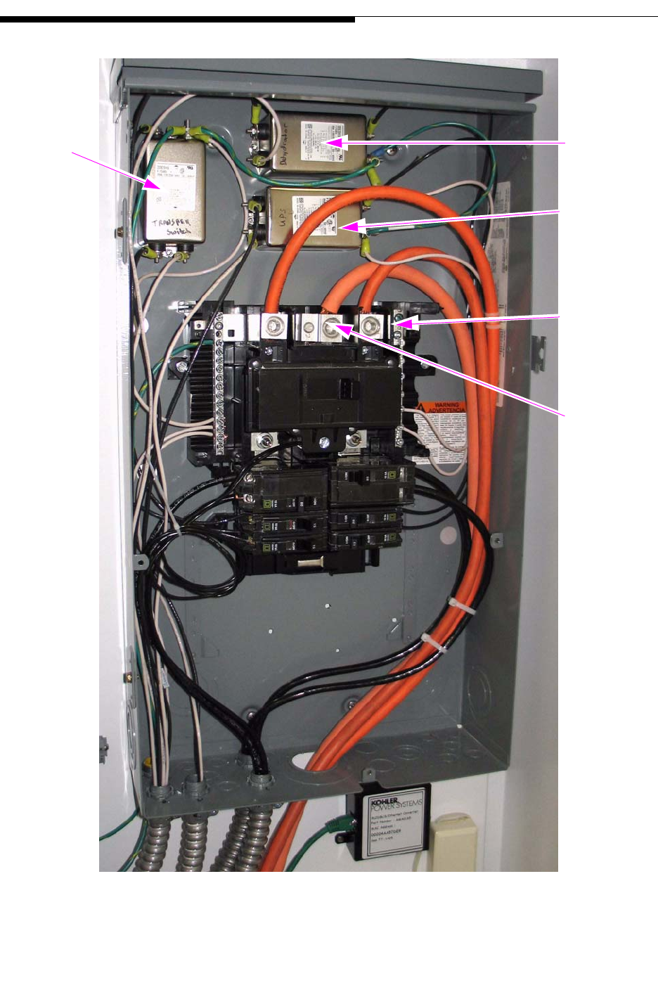
Figure 1-4 UAX AC Load Center, Front Cover Removed
Transfer
Switch
Line Filter
Dehydrator
Line Filter
AC
Neutral
Cabinet
Bonding
Terminal
UPS Line
Filter
2/9/10 888-2711-001 1-7
WARNING: Disconnect primary power prior to servicing.
Section 1 Introduction
Maxiva UAX Transmitter Outdoor Enclosure System
User Manual
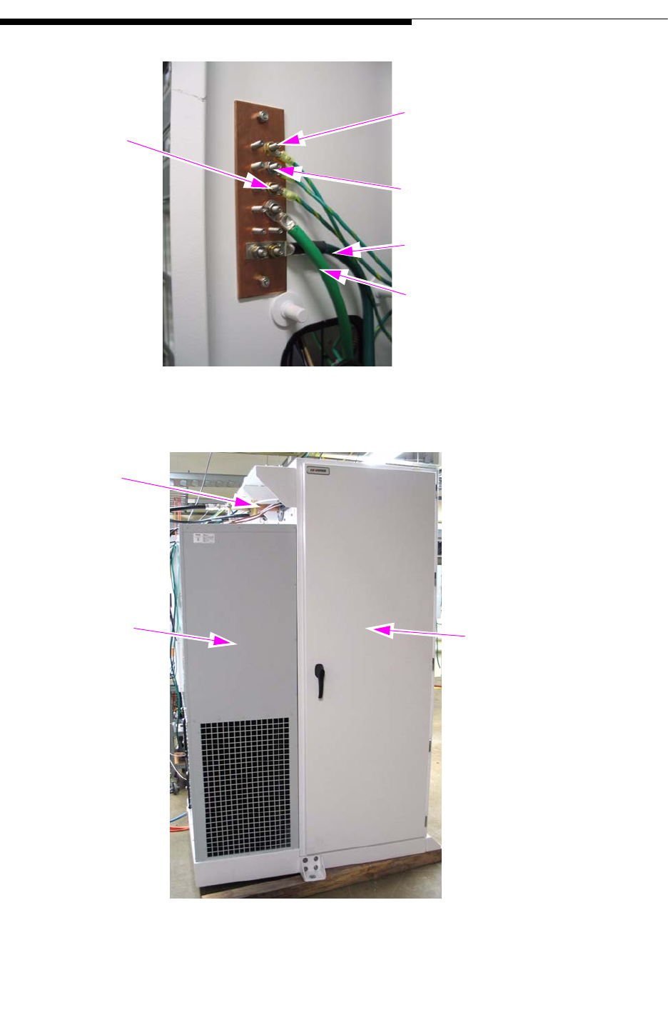
Figure 1-5 Copper Grounding Strip, Left Wall in AC Dist. Box
Figure 1-6 UAX Cabinet Rear View
To Line Filters
To Breaker Barrier Strip
To Air Conditioner
AC Mains/Facility Ground
To Transmitter Cabinet Ground
Lug
1-5/8" RF Out
to Antenna
Air Conditioner Transmitter
Cabinet
1-8 888-2711-001 2/9/10
WARNING: Disconnect primary power prior to servicing.
Section 1 Introduction User Manual
Maxiva UAX Transmitter Outdoor Enclosure System
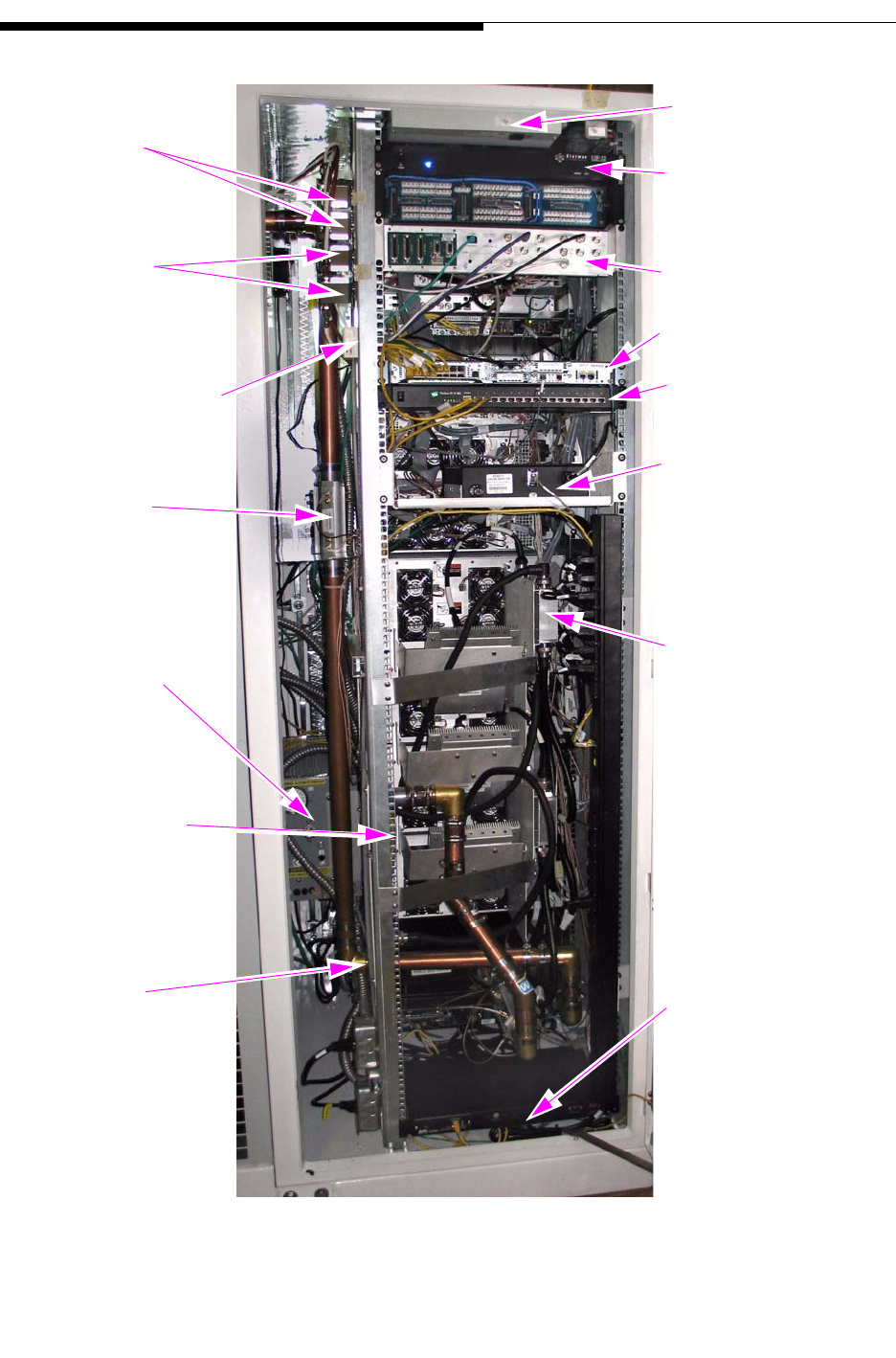
Figure 1-7 Transmitter Cabinet Rear View
GPS Surge
Suppressors
IRD Surge
Suppressors
Router Port
(for logging in to
router)
Directional
Couplers
Dehydrator
RF Combiner
Filter
Output Transfer Switch
(if UPS fails)
AC Power Strip
Optional Monitoring
Port Server/Switch
Hub
Network Router
Digital I/O Panel
Monitoring
Light
Equipment
Equipment
2/9/10 888-2711-001 1-9
WARNING: Disconnect primary power prior to servicing.
Section 1 Introduction
Maxiva UAX Transmitter Outdoor Enclosure System
User Manual
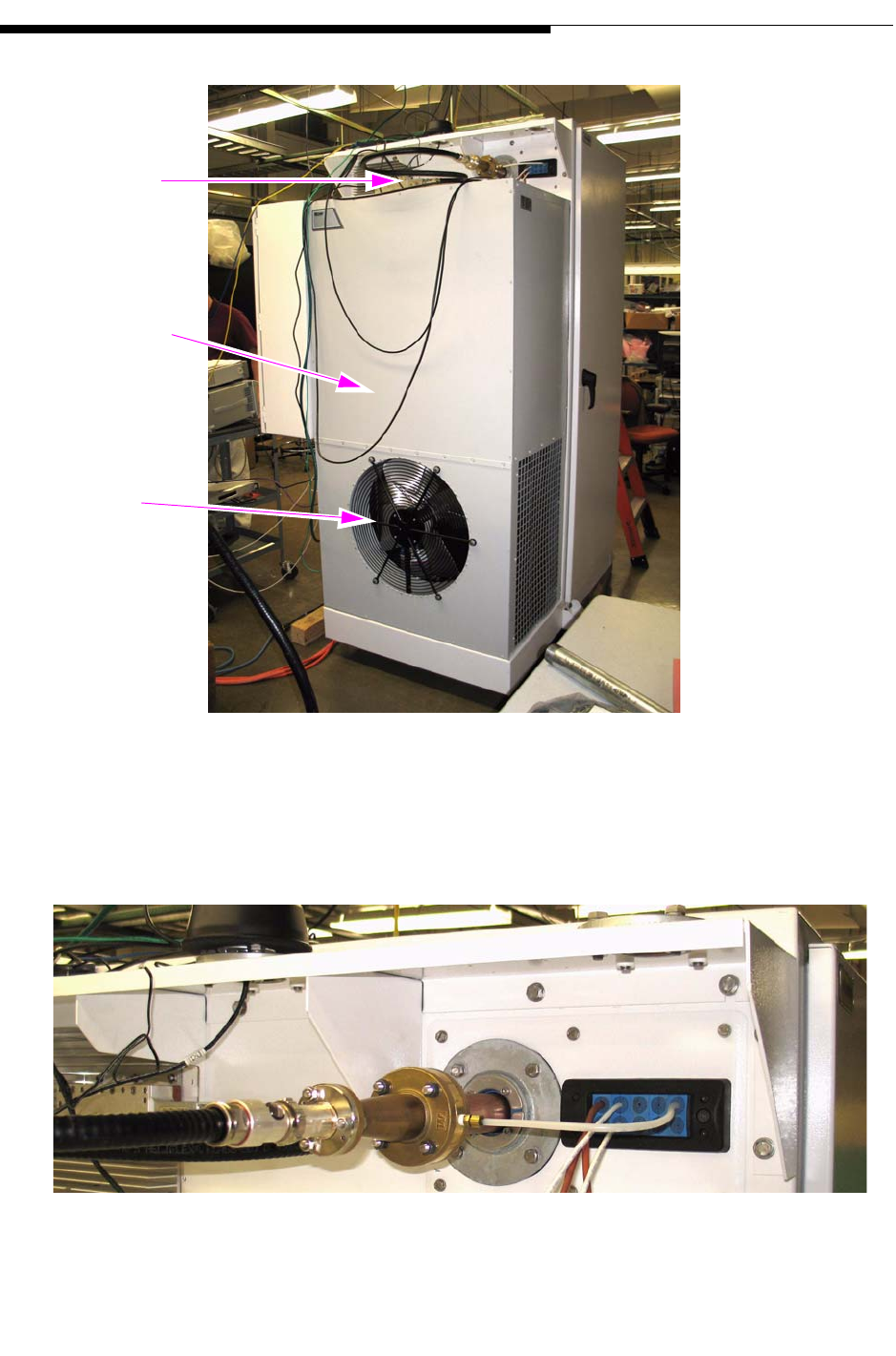
Figure 1-8 UAX Side View
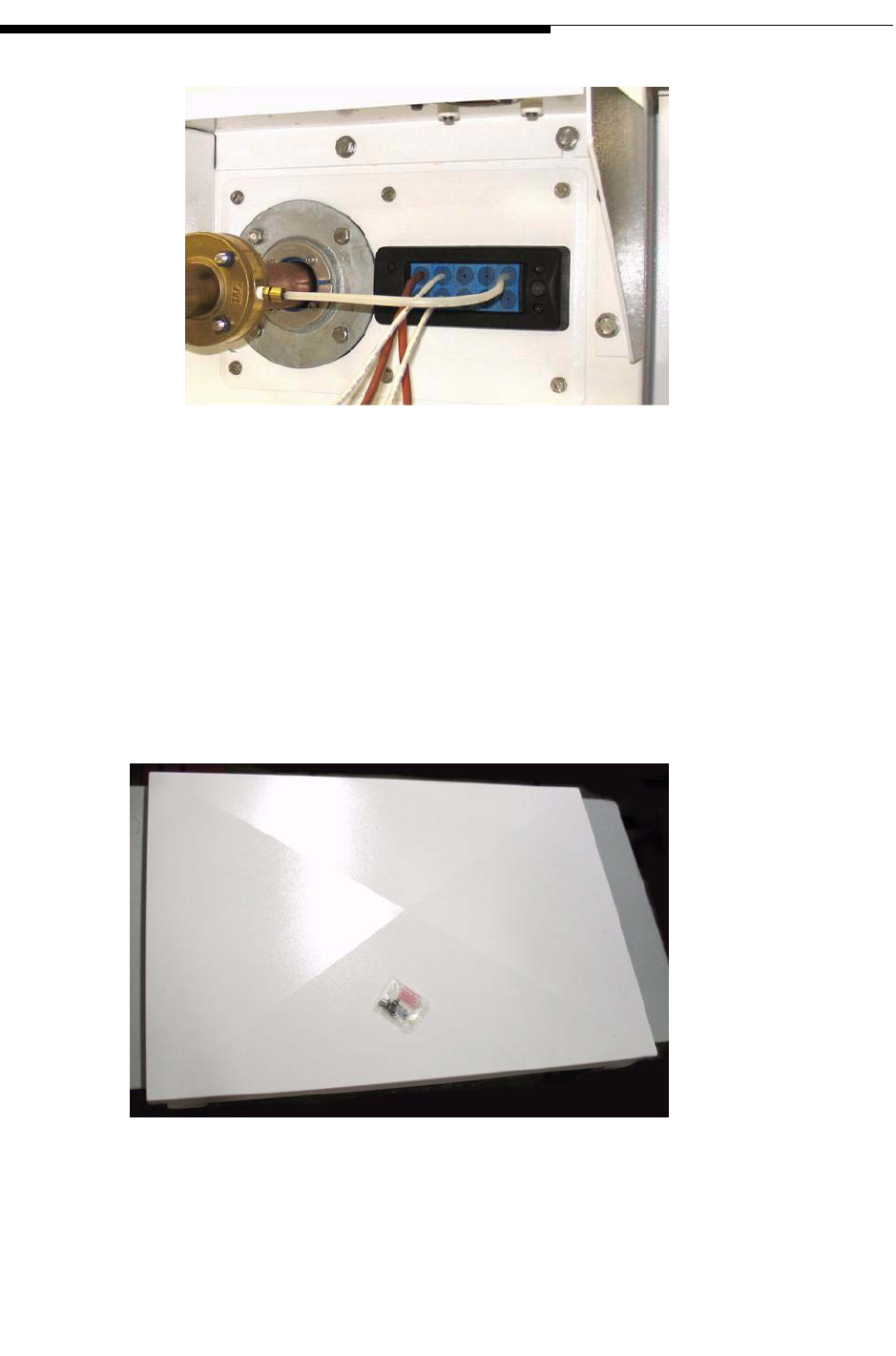
Figure 1-9 shows the transmitter RF 1-5/8" output connector which also serves as a gas
barrier.
Figure 1-9 RF Output
3kW Load &
RF Output
Connection
Air Conditioning
Enclosure
Heat Exchanger
Fan
1-10 888-2711-001 2/9/10
WARNING: Disconnect primary power prior to servicing.
Section 1 Introduction User Manual
Maxiva UAX Transmitter Outdoor Enclosure System
Figure 1-10 shows the 3kW dry load mounted in the bracket attached to the top of the
transmitter cabinet next to the RF output connector.
Figure 1-10 3 kW Dry Load
Figure 1-11 shows the customer interface panel mounted in the back of the transmitter
cabinet. Refer to the UAX transmitter manual 888-2693-001 section 2.7 for detailed
information
Figure 1-11 Customer I/O Panel
2/9/10 888-2711-001 1-11
WARNING: Disconnect primary power prior to servicing.
Section 1 Introduction
Maxiva UAX Transmitter Outdoor Enclosure System
User Manual
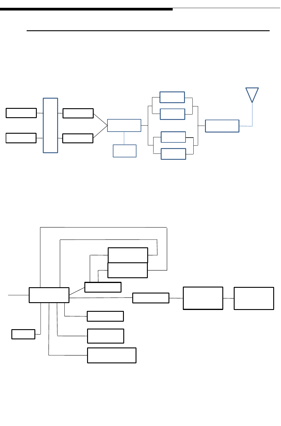
1.3 System Block Diagrams
Figure 1-12 is a simplified block diagram of the UAX enclosure system RF
transmission path.
Figure 1-12 RF Transmission Path
Figure 1-13 is a simplified block diagram of the communications path.
Figure 1-13 Communications Path
IRD (A)
IRD (B)
LPU
LPU
I/O RF Switch
TCU
PA Block
PA Block
PA Block
PA Block
Filter
RF Out
Router
T1
IRD B
IRD A
Port Server
Server
Monitor
Interface
Panel
Punch
Down
Panel
UPS
Auto Transfer
Switch
Modbus Ethernet
Converter (optional)
Console

1-12 888-2711-001 2/9/10
WARNING: Disconnect primary power prior to servicing.
Section 1 Introduction User Manual
Maxiva UAX Transmitter Outdoor Enclosure System
1.4 System Specifications
The following specifications refer to a typical 2kW outdoor enclosure system.
Specifications are subject to change and may vary depending on system configuration.
1.4.1 Environmental and Physical
Operating Temperature (ambient): -30oC. to 55oC.
Storage Temperature (ambient): -40oC to 70oC
Humidity: 0 to 100% humidity.
Altitude: Maximum 12,000 ft.
Weight: <1800 lbs.
1.4.2 AC power
Input voltage: 240V ±15% V, 60 Hz, Split Phase
Nominal current at maximum RF output power: < 165 A
Input Voltage Harmonics: < 5% THD
1.4.3 Connectors
Transmitter RF output: EIA 1-5/8”, 50 Ohm
ASI input: BNC, female, 75 Ohm
NOTE:
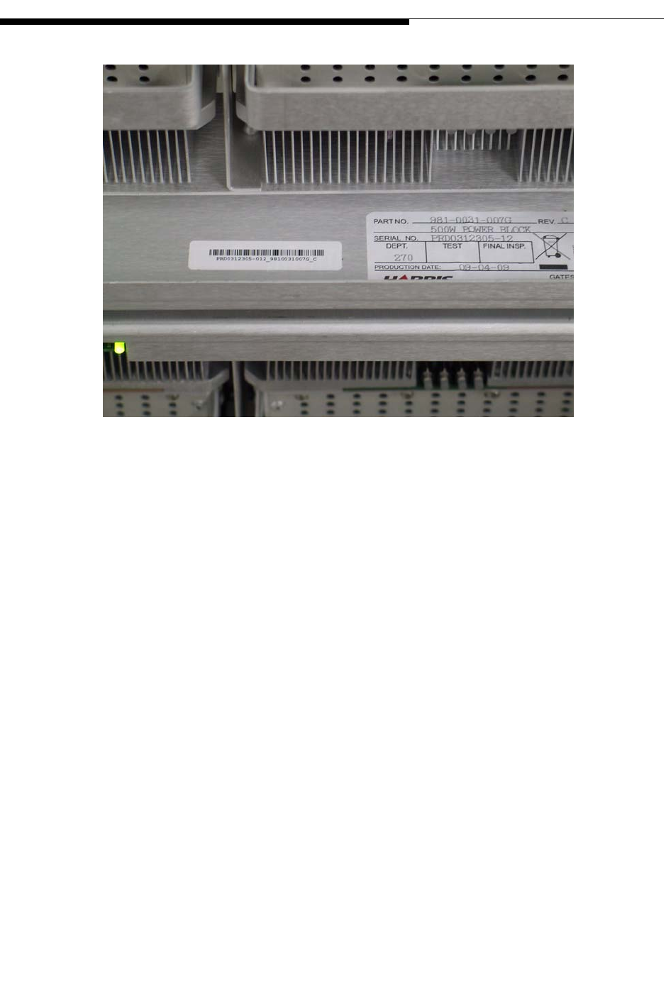
For Warranty purposes, each major component in the enclosure contains a bar
code strip. These bar codes are NOT to be removed.
2/9/10 888-2711-001 1-13
WARNING: Disconnect primary power prior to servicing.
Section 1 Introduction
Maxiva UAX Transmitter Outdoor Enclosure System
User Manual
Figure 1-14 Component Barcode Identification

1-14 888-2711-001 2/9/10
WARNING: Disconnect primary power prior to servicing.
Section 1 Introduction User Manual
Maxiva UAX Transmitter Outdoor Enclosure System

2/9/10 888-2711-001 2-1
WARNING: Disconnect primary power prior to servicing.
Maxiva UAX Transmitter Outdoor Enclosure System
User Manual
Section 2
Installation /
Initial Turn-On 2
2.1 Introduction
This section includes the information necessary for installation and initial turn on of an
UAX Outdoor Enclosure System.
2.2 Documentation
Following is a partial list of documentation that ships with the system. Find and save all
documentation. The top level Document Package numbers are shown below:
UAX Transmitter Outdoor Enclosure System Doc Package: 988-2711-001
Outdoor Enclosure System User manual: 888-2711-001
Enclosure and AC power drawings: 843-5602-523
UAX Enclosure System Interconnect drawing: 843-xxxx-xxx
UAX Outdoor Enclosure System Installation Manual: 888-2713-001
UAX Outdoor Enclosure System Commissioning Manual: 888-2712-001
The UAX Transmitter Document Package 988-2693-001 includes:
UAX technical manual: 888-2693-001
Drawing Package with a complete set of schematics for the transmitter
System: 943-5276-170
2-2 888-2711-001 2/9/10
WARNING: Disconnect primary power prior to servicing.
Section 2 Installation / Initial Turn-On
Maxiva UAX Transmitter Outdoor Enclosure System
User Manual
2.2.1 UAX Enclosure System Drawings
It is recommended that you look through the documentation package to familiarize
yourself with the information available. The installation and planning information is
given in the following drawings:
Std. Enclosure AC Distribution - 817-2307-076 shows overall AC wiring and has
information on system current requirements.
UAX Enclosure System Interconnect Diagram - Shows interconnect wiring between
transmitter and all peripheral systems.
2.3 Cabinet Placement
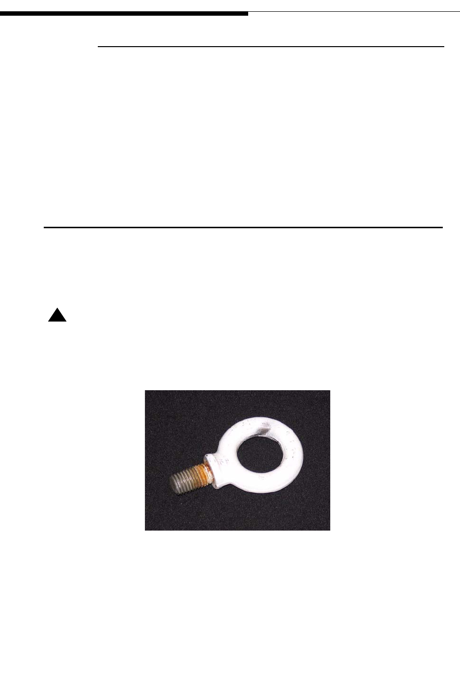
The entire enclosure can be lifted in place using the four (4) lifting eye bolts supplied
with the system. The eye bolts are shown in Figure 2-1.
! CAUTION:
LIFT STRAIGHT UP, EVENLY FROM EACH LIFT POINT TO AVOID PLACING STRESS
ON ANY ONE LIFT EYE.
Figure 2-1 Lifting Eye Bolt
2/9/10 888-2711-001 2-3
WARNING: Disconnect primary power prior to servicing.
Section 2 Installation / Initial Turn-On
Maxiva UAX Transmitter Outdoor Enclosure System
User Manual
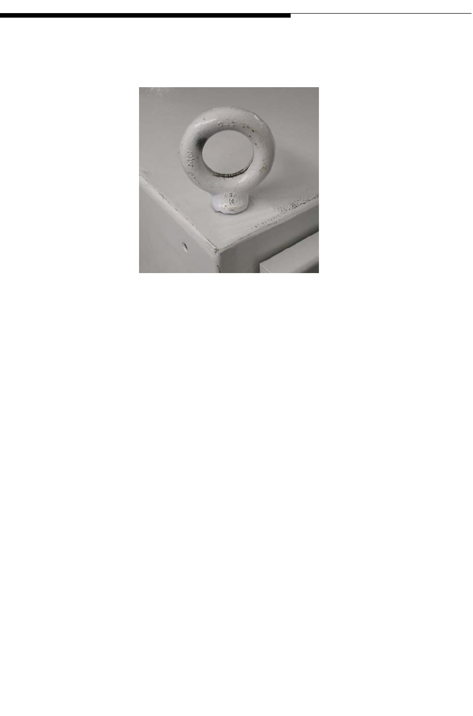
The four (4) Lifting Eye bolts screw into the top of the transmitter cabinet. One in each
corner. See Figure 2-2.
Figure 2-2 Lifting Eye Bolt On Top of Transmitter Cabinet
STEP 1 Install the lifting eyes. Be sure each lifting eye bolt is screwed all the
way in. Tighten the bolts in place using a wrench handle or bar.
STEP 2 Use an adequately sized hoist to lift the enclosure to its permanent
location.
STEP 3 Be sure the enclosure is level and securely positioned.
2-4 888-2711-001 2/9/10
WARNING: Disconnect primary power prior to servicing.
Section 2 Installation / Initial Turn-On
Maxiva UAX Transmitter Outdoor Enclosure System
User Manual
2.4 Cabinet Attachments
The enclosure is equipped with three (3) threaded antenna mounts located on the
bracket that is attached to the side of the transmitter cabinet directly above the air
conditioner cabinet. See Figure 2-3. The 2 GPS antenna supports screw into any two (2)
of these mounts.
STEP 1 Install the two mounts and GPS antennas. Tighten the mounts down
securely.
STEP 2 Feed the antenna wires through the moisture proof barrier under the
bracket close to the back of the transmitter. Figure 2-4. They connect to
the GPS surge suppressors. See Figure 1-7 on page 1-8.
Figure 2-3 GPS Antenna Mount
2/9/10 888-2711-001 2-5
WARNING: Disconnect primary power prior to servicing.
Section 2 Installation / Initial Turn-On
Maxiva UAX Transmitter Outdoor Enclosure System
User Manual
Figure 2-4 GPS Antenna Cables
STEP 3 Remove the eye bolts from the top of the transmitter cabinet.
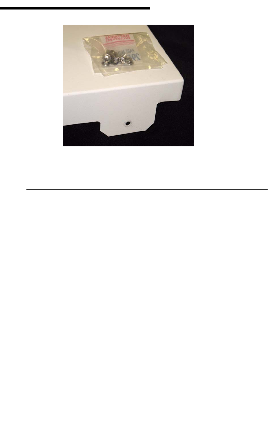
STEP 4 . The solar shield is a large cover designed to keep direct sunlight off the
top of the transmitter cabinet. Carefully unpack the shield from its box
and place on top of the transmitter cabinet. Figure 2-5 shows the shield
plus the bag of mounting screws. There are two (2) holes on each side
of the transmitter cabinet near the top. Use the supplied screws to attach
the shield to the transmitter cabinet. Refer to Figure 2-6.
Figure 2-5 Solar Shield
2-6 888-2711-001 2/9/10
WARNING: Disconnect primary power prior to servicing.
Section 2 Installation / Initial Turn-On
Maxiva UAX Transmitter Outdoor Enclosure System
User Manual
Figure 2-6 Solar Shield Mounts
2.5 Installation of Components Removed for Shipment
Selected components have been removed for shipment following factory assembly and
test. These components have been packed separately and should be unpacked as needed
for reassembly. These items must be stored in a safe, climate controlled, dry location
until needed for reassembly. Save all packing material until after commissioning to
facilitate returns if needed. Notify Harris immediately if damage is noted while
unloading the shipment.
The removed components include:
Removed from the front of the enclosure (and identified in Figure 1-2 on page 1-4) are
the two Satellite receivers and IRD’s, power amplifier modules in the LPU’s and power
amplifier blocks, and the mask filter.
Removed from the rear of the enclosure (and shown in Figure 1-7 on page 1-8) are the
network router, the port server/switch hub and the coaxial lines into and out of the mask
filter.
STEP 1 Install the mask filter in the front of the cabinet and secure it in
position.
STEP 2 Install the power amplifier blocks in the LPU’s and in the power
amplifier blocks. Read Section 2.5.1 Install PA Modules before
installing PA modules.
2/9/10 888-2711-001 2-7
WARNING: Disconnect primary power prior to servicing.
Section 2 Installation / Initial Turn-On
Maxiva UAX Transmitter Outdoor Enclosure System
User Manual
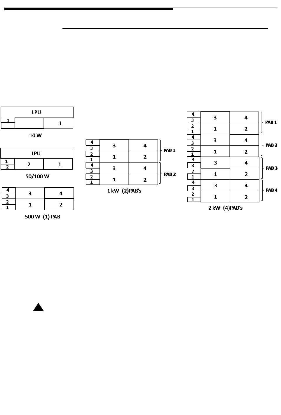
2.5.1 Install PA Modules
The PA Modules should be placed into the Low Power Unit (LPU) or Power Amplifier
Block (PAB) at this time. They should be inserted into the module slots in which they
were tested. In the LPU the PA modules are inserted with the cooling fins up. Each
module has a serial number which is recorded on the factory test data sheet as belonging
to a specific module slot, in the LPU or specific PAB block. The module slots for each
transmitter configuration are labeled as shown in Figure 2-7.
Figure 2-7 LPU & PAB Numbering Front View
PA modules in the PAB’s are installed in two orientations. The upper modules are
installed with the cooling fins up. The lower PAB modules are installed with the cooling
fins down. Fully seat each module by pressing firmly against the outside front edges on
the handles. Do not press on the center of the handle as it may deform.
! CAUTION:
IF THE MODULES DO NOT SEAT WITH MODERATE PRESSURE, REMOVE THE
MODULE TO CHECK FOR INTERFERENCE. DO NOT FORCE THE MODULES INTO
THE CHASSIS AS THIS MAY CAUSE DAMAGE TO THE RF CONNECTOR ON THE
BACK OF THE MODULE OR ON THE PA BACKPLANE BOARD.
STEP 3 Install the network server and secure to the rack.

2-8 888-2711-001 2/9/10
WARNING: Disconnect primary power prior to servicing.
Section 2 Installation / Initial Turn-On
Maxiva UAX Transmitter Outdoor Enclosure System
User Manual
STEP 4 Install the two satellite receivers and IRD units and secure to the
rack.
STEP 5 Install the coaxial line assemblies at the input and output of the mask
filter.
STEP 6 Install the RF sample cables on the directional coupler located at the
filter input. The location of these cables is described in the Wiring
Diagram, XMTR UAX 2kW Dual Drive with TCU Racked, drawing
number 843-5602-409 which can be found in the 943-5276-170 drawing
package which is part of the 988-2693-001 documentation package.
STEP 7 Install the port server/switch hub and secure it in rack.
! CAUTION:
CARE MUST BE TAKEN TO PROPERLY CONNECT THESE CABLES IN THEIR
PROPER LOCATION ON THE FORWARD OR REVERSE PORTS OF THE COUPLER.
FAILURE TO HOOK THEM UP PROPERLY WILL RESULT IN POOR PERFORMANCE.
STEP 8 Install the network router and secure it in the rack.
STEP 9 Using the outdoor enclosure Interconnect Drawing and the UAX wiring
diagram connect all input and outputs to the installed components.

2/9/10 888-2711-001 2-9
WARNING: Disconnect primary power prior to servicing.
Section 2 Installation / Initial Turn-On
Maxiva UAX Transmitter Outdoor Enclosure System
User Manual
2.6 AC/Ground connections
2-10 888-2711-001 2/9/10
WARNING: Disconnect primary power prior to servicing.
Section 2 Installation / Initial Turn-On
Maxiva UAX Transmitter Outdoor Enclosure System
User Manual
2.7 Ground connections
! CAUTION:
ALL CONNECTIONS LISTED IN THIS SECTION SHOULD BE VERIFIED WITH THE
SCHEMATICS BEFORE INITIAL TURN ON.
! CAUTION:
THE USE OF A SYSTEM SURGE SUPPRESSOR IS RECOMMENDED. THE SYSTEM
SURGE SUPPRESSOR WILL BE PROVIDED BY THE CUSTOMER.
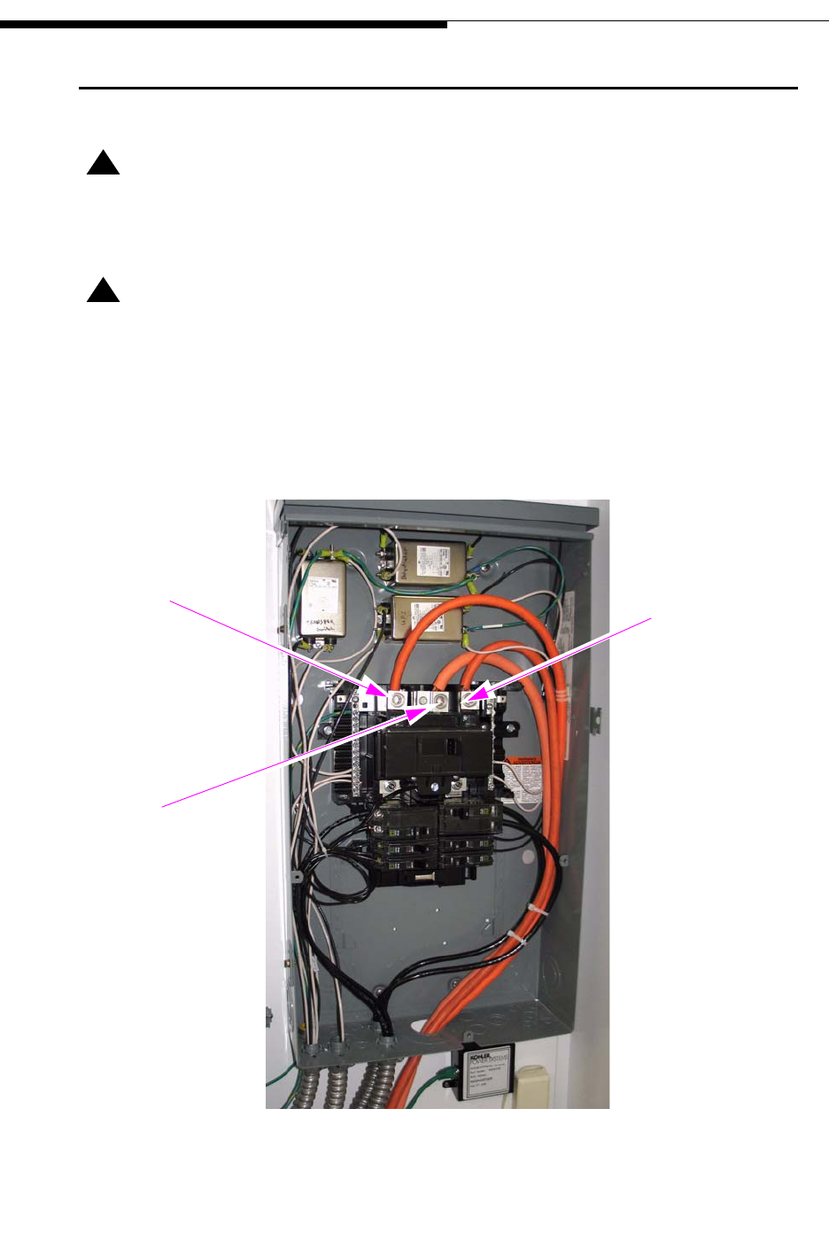
Figure 2-8 shows the AC load center with the breaker cover removed. The split-phase
AC wires enter through the bottom of the cabinet and connect to the top of the breaker
assembly. The neutral connects to the middle terminal.
Figure 2-8 Transmitter AC Load Center AC Mains Connections
L1 L2
Neutral
2/9/10 888-2711-001 2-11
WARNING: Disconnect primary power prior to servicing.
Section 2 Installation / Initial Turn-On
Maxiva UAX Transmitter Outdoor Enclosure System
User Manual
The UAX Enclosure System operates on split phase 220- 240 VAC 50/60Hz power.
Refer to the AC wiring diagram in the transmitter schematic package.
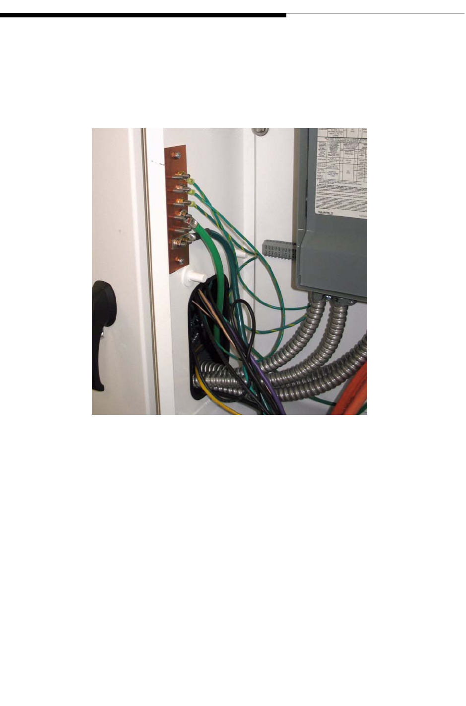
Figure 2-9 shows the facility safety ground copper buss bar for the enclosure system. It
is located on the left wall inside the AC distribution box.
Figure 2-9 System Safety Ground Copper Buss Bar
STEP 1 Verify all circuit breakers on the front of the breaker panel in the
transmitter cabinet are OFF. Refer to Figure 2-10.
STEP 2 Verify that the AC mains are disabled before proceeding.

2-12 888-2711-001 2/9/10
WARNING: Disconnect primary power prior to servicing.
Section 2 Installation / Initial Turn-On
Maxiva UAX Transmitter Outdoor Enclosure System
User Manual
Figure 2-10 Transmitter AC Distribution Panel
STEP 3 Connect a ground cable from the copper ground buss bar to the
station ground. This connection is made at the bottom of the copper
buss bar. It is routed through the same hole in the bottom of the AC
Distribution Box used to route the AC power wires.
STEP 4 Following all local codes hook up the AC mains.
STEP 5 Hook up remaining AC mains connections.
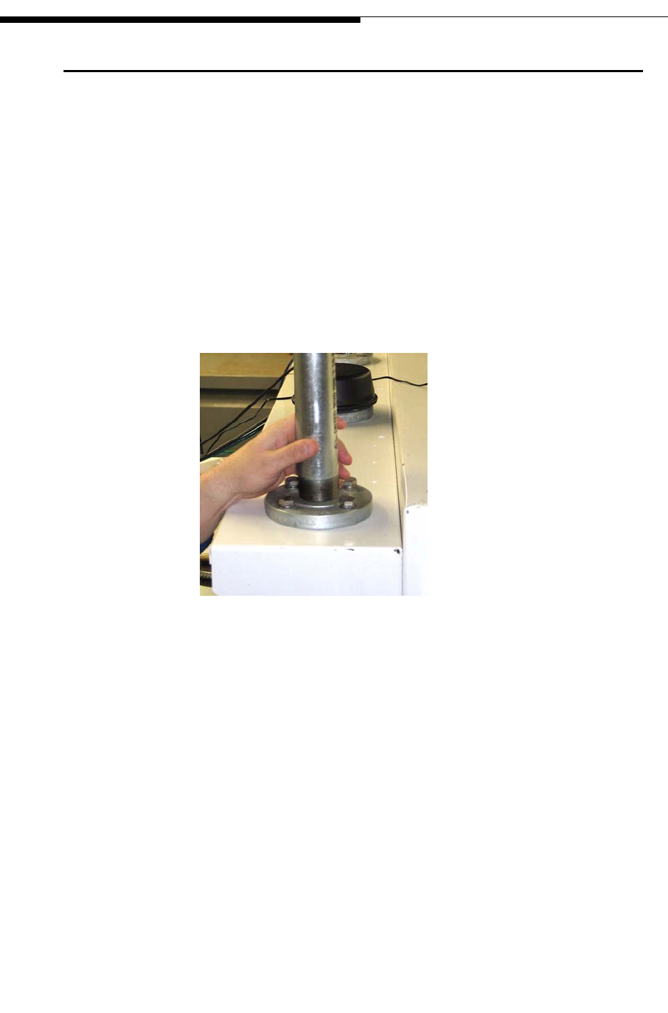
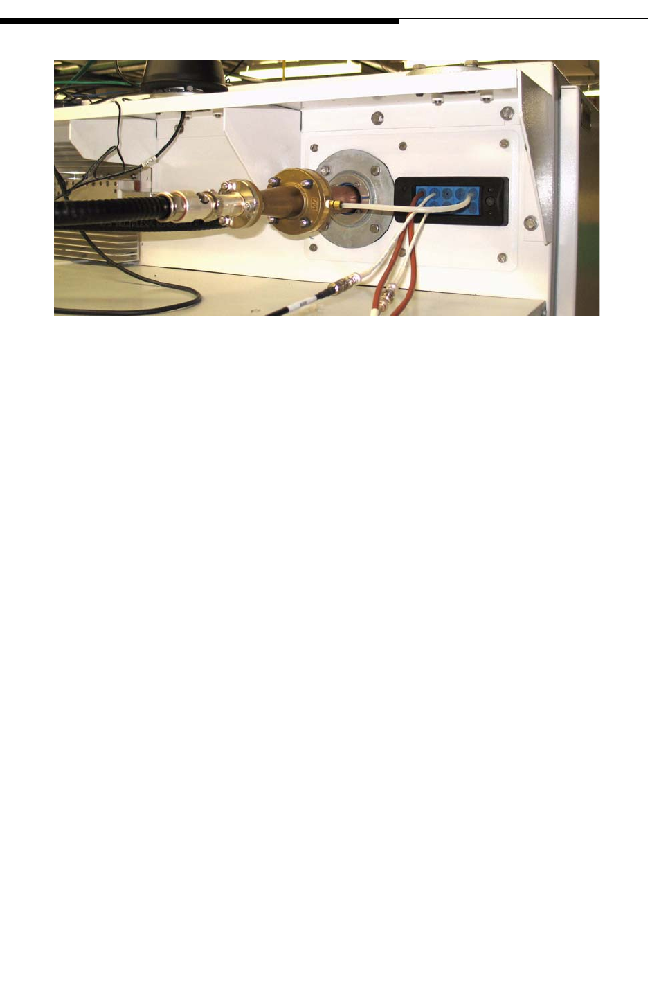
2.8 Transmitter RF output connection
STEP 1 Verify the quality of the RF load or antenna.
STEP 2 Install the RF output connection to the transmitter.
STEP 3 Tighten the flange bolts in the RF coaxial line.
The RF output uses a standard EIA, flanged "1 5/8" RF connector. The RF output is
located on the side of the transmitter above the air conditioning cabinet. Refer to Figure
2-11.
2/9/10 888-2711-001 2-13
WARNING: Disconnect primary power prior to servicing.
Section 2 Installation / Initial Turn-On
Maxiva UAX Transmitter Outdoor Enclosure System
User Manual
Figure 2-11 Transmitter RF Output Connection
2-14 888-2711-001 2/9/10
WARNING: Disconnect primary power prior to servicing.
Section 2 Installation / Initial Turn-On
Maxiva UAX Transmitter Outdoor Enclosure System
User Manual
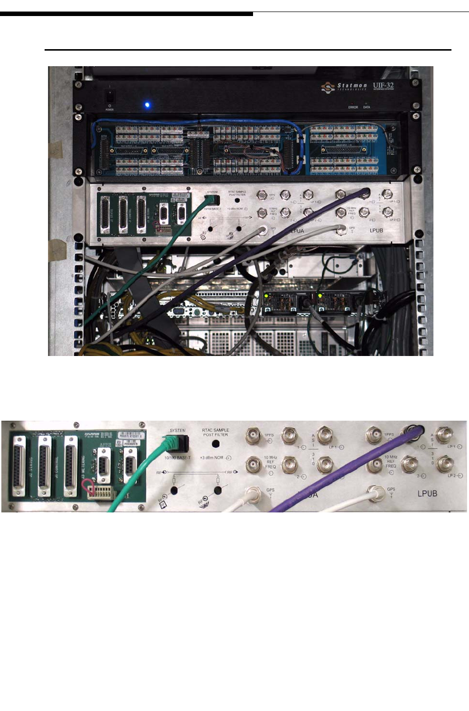
2.9 Signal Connections
Figure 2-12 Customer I/O Panel on Back of Transmitter
Figure 2-13 Customer I/O Exciter Connections
Figure 2-13 shows the Exciter connections on the Customer I/O panel. Depending on
the system model, the UAX system may or may not include two LPU’s (exciters).
Refer to the UAX transmitter manual for connection details.
2/9/10 888-2711-001 2-15
WARNING: Disconnect primary power prior to servicing.
Section 2 Installation / Initial Turn-On
Maxiva UAX Transmitter Outdoor Enclosure System
User Manual
2.10 Customer Remote Control & Interlock Connections
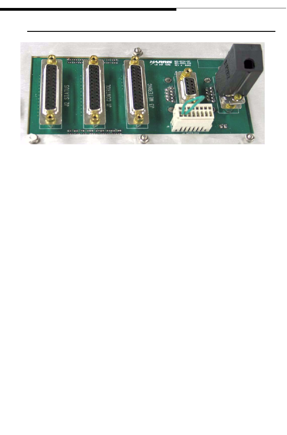
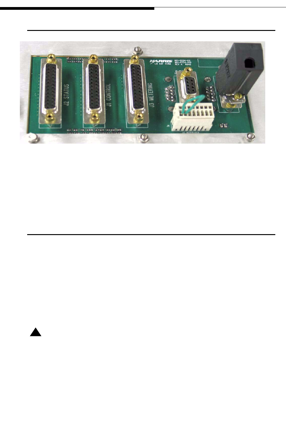
Figure 2-14 Customer Remote Control & Interlock Connections
The circuit board mounted on the left side of the Customer I/O panel (Figure 2-14), is
used for remote control connection to the transmitter. J4 is an Interlock connector that
can be used to add peripheral devices such as an antenna switch into the transmitter
interlock system. Refer to the UAX transmitter manual for connection details.
2-16 888-2711-001 2/9/10
WARNING: Disconnect primary power prior to servicing.
Section 2 Installation / Initial Turn-On
Maxiva UAX Transmitter Outdoor Enclosure System
User Manual
2.11 Customer Remote Control & Interlock Connections
Figure 2-15 Customer Remote Control & Interlock Connections
The circuit board mounted on the left side of the Customer I/O panel (Figure 2-14), is
used for remote control connection to the transmitter. J4 is an Interlock connector that
can be used to add peripheral devices such as an antenna switch into the transmitter
interlock system. Refer to the UAX transmitter manual for connection details.
2.12 Initial Turn-On
Read and understand the entire initial turn-on procedure before starting. Descriptions
and operational instructions for TCU and LPU GUI screens is given in Section 3
"Operation" in the UAX Transmitter manual.
STEP 1 Make sure the output RF line is connected properly. If connecting to a
load, verify the load connections are proper and that load conditions are
met.
! CAUTION:
THE TRANSMITTER RF LINE MUST BE CONNECTED TO A KNOWN GOOD LOAD
OR ANTENNA. IF THE CONDITION OF THE LOAD OR ANTENNA ARE IN DOUBT
THEY SHOULD BE MEASURED WITH A NETWORK ANALYZER PRIOR TO TURNING
ON THE TRANSMITTER.

2/9/10 888-2711-001 2-17
WARNING: Disconnect primary power prior to servicing.
Section 2 Installation / Initial Turn-On
Maxiva UAX Transmitter Outdoor Enclosure System
User Manual
STEP 2 Verify all ground connections are secure and the AC power feed wire
connections from the facility AC power source are tight and of proper
capacity (correct gauge wire, breaker size etc.).
STEP 3 Verify the breaker cover is properly installed in the AC Distribution Box.
STEP 4 Check the transmitter cabinet for any loose hardware. Visually inspect
that all cable/wire/cord connections are secure.
STEP 5 Check that all breakers in the Transmitter Enclosure System AC
Distribution Box are OFF. Also all 18 breakers on the AC distribution
panel at the top of the transmitter cabinet are OFF.
STEP 6 Apply AC primary power to the enclosure system. Be ready to quickly
disconnect the power if necessary.
STEP 7 In the AC Distribution Box, turn the Main Breaker ON.
STEP 8 Turn on the Air Conditioner breaker. The A/C system should start
immediately.
STEP 9 Turn on the Transmitter breaker, then the remaining breakers.
STEP 10 If the system has a UPS unit, it must be turned ON to power the rest of
the system. Check the UPS manufacturer’s manual for procedure.
STEP 11 To turn the Transmitter on, refer to the procedure in the Transmitter
manual. It begins by turning each of the transmitter breakers ON. These
are the breakers in the breaker panel at the top of the transmitter. Only
the transmitter is connected to these breakers.
STEP 12 After the Transmitter is turned ON, verify power out is correct on the
TCU Home Screen. Refer to the transmitter manual for detailed
operation of all transmitter functions and operation.
NOTE:
Make sure the transmission data stream is being fed into the exciter. If not, the
transmitter will stay in a Mute condition and will not produce RF.
STEP 13 Some individual pieces of equipment (non-supplied equipment -
computer, satellite receivers etc.) may require turning individual power
switches on. Check the owner’s manual for each piece for turn-on
procedure.
STEP 14 Check the equipment mounted in the back of the transmitter rack
(Monitoring, Router, Server, etc.) to verify all is powered up.
2-18 888-2711-001 2/9/10
WARNING: Disconnect primary power prior to servicing.
Section 2 Installation / Initial Turn-On
Maxiva UAX Transmitter Outdoor Enclosure System
User Manual
NOTE:
Equipment should power up automatically when the breakers are turned ON. The
enclosure is designed so that breakers activate all equipment.
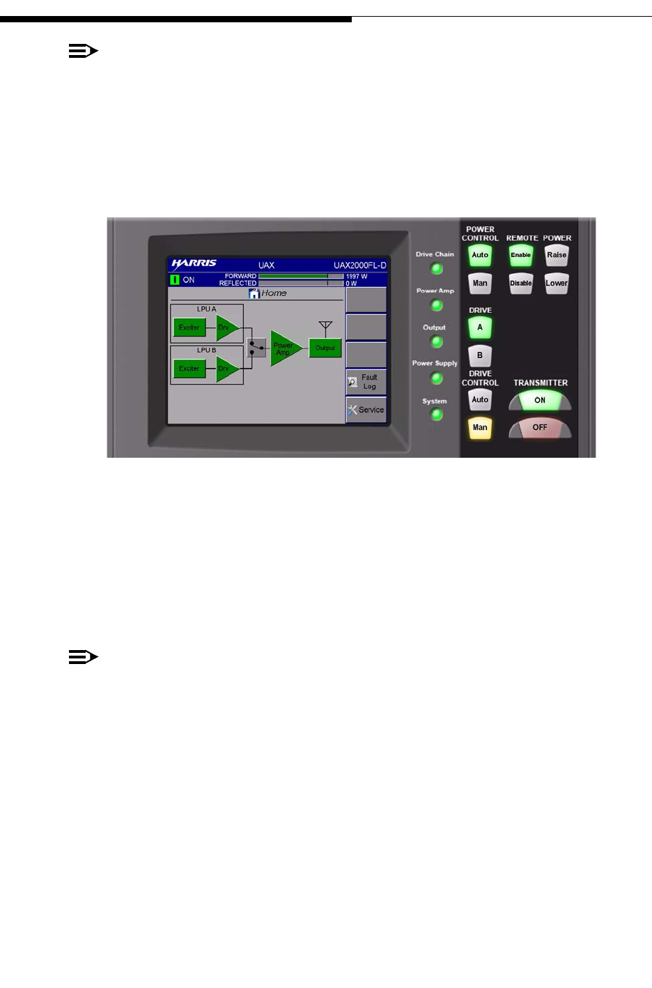
At this time, the TCU and Home screen should appear as shown in Figure 2-16. All
LEDs should be illuminated GREEN. If any are RED, refer to the Transmitter manual
for detailed information. Actual forward power can be read off the top bar graph.
Figure 2-16 Transmitter TCU Screen and Controls
This completes the initial Turn-On procedure. Do a visual inspection of the entire
system to verify the system is operating properly, verify the RF connections are secure,
and confirm the Air Conditioning unit is operating and cooling the enclosure.
STEP 15 Close all doors and secure them before leaving.
NOTE:
The cabinet doors do not contain locks. However, customer supplied locks can be
attached to each door through the hole in the handles. See Figure Figure 2-17.

2/9/10 888-2711-001 2-19
WARNING: Disconnect primary power prior to servicing.
Section 2 Installation / Initial Turn-On
Maxiva UAX Transmitter Outdoor Enclosure System
User Manual
Figure 2-17 Enclosure Door Handles

2-20 888-2711-001 2/9/10
WARNING: Disconnect primary power prior to servicing.
Section 2 Installation / Initial Turn-On
Maxiva UAX Transmitter Outdoor Enclosure System
User Manual

2/9/10 888-2711-001 3-1
WARNING: Disconnect primary power prior to servicing.
Maxiva UAX Transmitter Outdoor Enclosure System
User Manual
Section 3
Operation &
Maintenance 3
3.1 Introduction
This section provides operational information for the UAX Outdoor Enclosure
Transmitter System
NOTE:
Operation of the UAX Transmitter and the LPU (low power unit) is covered in a
separate manual which ships with the system.
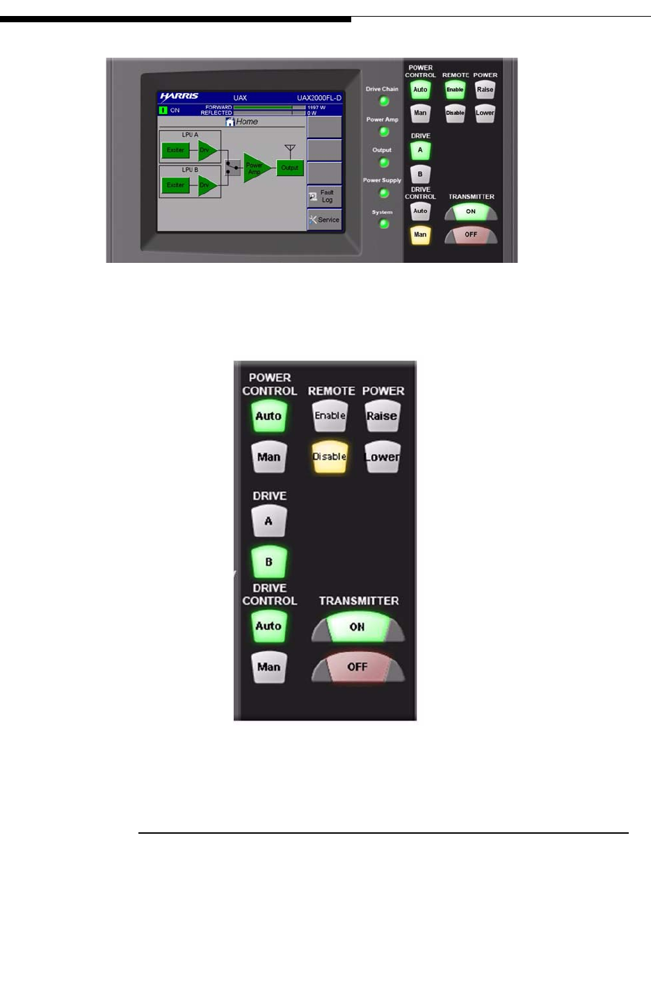
3.2 Transmitter Control Unit (TCU)
The TCU front panel user interface utilizes a 1/4 VGA, LCD touchscreen display. See
Figure 3-1. This touchscreen display uses software buttons to monitor the transmitter.
There are 12 hardware buttons for the primary transmitter functions shown in
Transmitter Control Panel. Refer to the UAX Transmitter Manual for details.
The TCU Home screen shows the total output power of the transmitter before the output
filter. Note that no VSWR is displayed. The VSWR is read off the LPU (low power
unit....Exciters) screens.
3-2 888-2711-001 2/9/10
WARNING: Disconnect primary power prior to servicing.
Section 3 Operation & Maintenance
Maxiva UAX Transmitter Outdoor Enclosure System
User Manual
Figure 3-1 Transmitter TCU Screen
Figure 3-2 Transmitter Control Panel
3.2.1 Control Buttons overview:
•TRANSMITTER "ON" and "OFF" (the main transmitter on/off buttons)
•POWER "Raise" and "Lower" (to raise or lower transmitter output power)

2/9/10 888-2711-001 3-3
WARNING: Disconnect primary power prior to servicing.
Section 3 Operation & Maintenance
Maxiva UAX Transmitter Outdoor Enclosure System
User Manual
•POWER CONTROL "Auto" and "Man" (for automatic or manual output power con-
trol) to manually raise or lower the transmitter power, press the "Man" button. Then
press Raise or Lower to adjust output power. Once the output power has been set to
the desired level, press the "Auto" button and the TCU will maintain that level auto-
matically.
•DRIVE "A" and "B" (To choose Drive Chain A or Drive Chain B)
•DRIVE CONTROL "Auto" and "Man" (In "Manual" mode, operator can select Drive
Chain A or B. In "Auto" mode, the TCU will automatically switch drive chains if a
fault occurs in the active drive chain.
•REMOTE "Enable" and "Disable" (To block all remote control operations of the
transmitter). By pressing the "Disable" button, prevents a remote control operator
from performing any transmitter function while a local operator/engineer is perform-
ing tests or maintenance on the transmitter.
NOTE:
Be sure to press the "Enable" button before leaving the transmitter facility.
When leaving the enclosure facility check to make sure the control buttons are lit as
follows:
•POWER CONTROL: Auto
•DRIVE: A
•DRIVE CONTROL: Auto
•REMOTE: Enable
•TRANSMITTER: ON
Figure 1-2 in Chapter 1 shows a Server (Ethernet) port attached to the rack to the right
of the TCU. A shelf for a laptop pc is provided on the transmitter door. Simply lift until
it clicks in position. Connect the laptop to the server port which provides access to the
entire system.
See Figure 1-6, "UAX Cabinet Rear View", on page 1 -7. Attached to the left side of the
rack is another router port. This port connects to the Console Command Port on the
back of the system router. This allows the technician to access the server and set/
program the parameters of the system. (That attached port allows easy connection to the
router without having to remove the router from the rack to gain access to the Console
Port). Also note the power switch is also located on the back of the router.

3-4 888-2711-001 2/9/10
WARNING: Disconnect primary power prior to servicing.
Section 3 Operation & Maintenance
Maxiva UAX Transmitter Outdoor Enclosure System
User Manual
Figure 3-3 Router Rear View
The rest of the system components basically function On or Off and don’t require any
adjustments.
NOTE:
Access to the Dehydrator ON/OFF switch is through the back transmitter cabinet
door. Note the pressure meter should read about 5 PSI.
3.3 Maintenance
This section contains the maintenance procedures for the UAX Outdoor Enclosure
Transmitter System. Always refer to the manufacturer’s manual of the individual
components for specific maintenance procedures.
The enclosure system overall, requires very little maintenance. The air conditioning
system should be checked periodically and maintained as you would normally maintain
any air conditioner. The condenser coils should have a routine cleaning every six
months. If the enclosure is exposed to high levels of dust and dirt, cleaning should occur
more often. Simply spray the condenser coils with a garden hose. Avoid high pressure
spray as this may damage the fragile aluminum fins.
There are no air filters to change on the A/C unit.
Console Port Power On/Off

2/9/10 888-2711-001 4-1
WARNING: Disconnect primary power prior to servicing.
Maxiva UAX Transmitter Outdoor Enclosure System
User Manual
Section 4
Parts List 4
4.1 Replaceable Parts List
Table 4-1 "UAX-2000FL & SHELTER, QUALCOMM" - - - - - - 9950068111G (J) 4-2
Table 4-2 "KIT, FLO OPTION" - - - - - - - - - - - - - - - - - 9710035027G (A) 4-3
Table 4-3 KIT; RF SYSTEM USED WITH DIELECTRIC FILTER 971 0041 026 (D) 4-3
Table 4-4 "ASSY, 2KW AC DISTRIBUTION PANEL" - - - - - - 971 0041 029 (C) 4-3
Table 4-5 "ASSY, HEATSINK LOAD"- - - - - - - - - - - - - - 971 0041 044 (A) 4-4
Table 4-6 KIT; RF SYSTEM USED WITH RFS FILTER - - - - - 971 0041 060 (B) 4-4
Table 4-7 "XMTR, 2KW MAXIVA UAX" - - - - - - - - - - - - 9810031012G (G) 4-4
Table 4-8 "ASSY, 1KW POWER BLOCK" - - - - - - - - - - - 9710041019G (J) 4-4
Table 4-9 1000 WATT SYSTEM REJECT LOAD - - - - - - - 9710041016G (E1) 4-4
Table 4-10 500W POWER BLOCK - - - - - - - - - - - - - - - 9810031037G (B) 4-5
Table 4-11 BASIC POWER BLOCK- - - - - - - - - - - - - - 9810031038G (J) 4-5
Table 4-12 "XMTR, MAXIVA UAX 50W"- - - - - - - - - - - - 9810031004G (J) 4-6
Table 4-13 "BASIC, MAXIVA UAX 10-100W, LPU" - - - - - - 9810031036G (G) 4-7
Table 4-14 "KIT, 2KW TCU / DUAL LPU OPTION" - - - - - - - 9810031020G (H) 4-8
For table above and in tables that follow in this section the (X) or (XX) after the table title part
number is the revision level of that bill of material and is for reference only.

4-2 888-2711-001 2/9/10
WARNING: Disconnect primary power prior to servicing.
Section 4 Parts List
Maxiva UAX Transmitter Outdoor Enclosure System
User Manual
Table 4-1 "UAX-2000FL & SHELTER, QUALCOMM" - 9950068111G (J)
Harris PN Description Qty UM Ref Des
10 B/M NOTE: 0 DWG
448 0965 200 "OUTDOOR ENCLOSURE, ALUMINUM, WITH 5 TON HVAC UNIT."1 EA
583 0118 001 "RELAY, COAXIAL TRANSFER" 1 EA
620 2686 000 "DEHYDRATOR, OUTDOOR ENCLOSURE, SPECIAL DESIGN, 200 SCFD"1 EA
620 2964 000 "POWER SPLITTER, 2-WAY" 4 EA
620 3261 000 "ADAPTER, 1-5/8"" TO 7/16 FEMALE" 1 EA
620 3268 000 "CABLE, COAX, 7/16"" PLUG" 1 EA
646 1483 000 "NAMEPLATE, HARRIS LOGO" 1 EA
646 1701 000 "NAMEPLATE, MAXIVA" 1 EA
778-241-040 SCREWED CABLE GLAND 1 EA
783 0048 041 "DIE FILTER, DR 2 KW" 1 EA
783 0048 042 "RFS FILTER, DR 2KW" 0 EA
790 5357 100 ENCLOSURE AC DISTRIBUTION & MUX EQUIPMENT 2KW UAX1 EA
939 8221 031 "PNL, 19.0X1.718X0.125 HF142" 1 EA
943 5567 592 "PLATE, CABLE GLAND" 1 EA
943 5602 220 FILTER BRACKET LEFT 1 EA
943 5602 221 FILTER BRACKET RIGHT 1 EA
943 5602 244 LOAD MOUNTING BRACKET 1 EA
943 5602 268 "PANEL, I/O ANALOG BLANK" 1 EA
943 5602 342 "PANEL, COMNINER & SPLITTER MOUNTING" 1 EA
943 5602 343 "SHELF, AIRLINK MONITOR MOUNTING" 1 EA
943 5602 345 "BRACKET, SUPPORT" 14 EA
943 5602 346 "BRACKET, SUPPORT, AIRLINK MONITOR" 2 EA
943 5602 361 "SLIDE, RACK MOUNT" 2 EA
943 5602 363 "BRACKET, PWR STRIP MTG" 2 EA
943 5602 413 "PANEL, I/O, OUTDOOR ENCLOSURE" 1 EA
943 5602 417 "BRACKET, REAR SUPPORT, RIGHT" 2 EA
943 5602 418 "BRACKET, REAR SUPPORT, LEFT" 2 EA
943 5602 420 "BRACKET, FILTER SUPPORT" 2 EA
943 5602 434 "PANEL, FRONT, 500W" 4 EA
943 5602 440 "PANEL, COMBINER MTG" 1 EA
943 5602 448 "BRACKET, TCU MTG" 2 EA
943 5602 451 "PANEL, I/O. CONNECTOR MTG" 1 EA
943 5603 072 "BAR, GROUNDING" 1 EA
952 9248 052 "CABLE, UAX AC 500W " 1 EA
952 9248 053 "CABLE, UAX AC 1KW " 1 EA
952 9248 054 "CABLE, UAX AC 2KW " 1 EA
952 9248 056 "CABLE, UAX RACK/SINGLE LPU " 1 EA
9710035027G "KIT, FLO OPTION" 2 EA
9710035030G "KIT, GPS OPTION" 2 EA
971 0041 026 KIT; RF SYSTEM USED WITH DIELECTRIC FILTER 1 EA
971 0041 029 "ASSY, 2KW AC DISTRIBUTION PANEL" 1 EA
971 0041 044 "ASSY, HEATSINK LOAD" 1 EA
971 0041 060 KIT; RF SYSTEM USED WITH RFS FILTER 0 EA
9810031012G "XMTR, 2KW MAXIVA UAX" 1 EA
9810031020G "KIT, 2KW TCU / DUAL LPU OPTION" 1 EA
988 2693 001 "DOC PACKAGE, MAXIVA UAX" 2 EA
BRD 100S TFN "LOAD, 100W, ’N’ JACK" 1 EA

2/9/10 888-2711-001 4-3
WARNING: Disconnect primary power prior to servicing.
Section 4 Parts List
Maxiva UAX Transmitter Outdoor Enclosure System
User Manual
Table 4-2 "KIT, FLO OPTION" - 9710035027G (A)
Harris PN Description Qty UM Ref Des
861 1135 252 APEX M2X SW/FW FLO COMPLETE APP 0 DWG
9710035014G ASM-SUB-BLANK PANEL B 1 EA
Table 4-3 KIT; RF SYSTEM USED WITH DIELECTRIC FILTER - 971 0041 026 (D)
Harris PN Description Qty UM Ref Des
620 0231 000 "BARRIER, GAS 1-5/8" 1 EA
620 0276 000 ADAPTER 1-5/8 IN. 2 EA
620 0631 000 "ELBOW, EQUAL, 1-5/8, 90 DEG" 6 EA
620 0662 000 "COUPLING, SLEEVE, 1-5/8" 13 EA
620 1910 000 "ELBOW 45 DEG 1-5/8""" 2 EA
839 8016 003 "ASSY INSTR, 3.75"" LG, TUBING COAX" 1 DWG
839 8016 008 "ASSY INSTR, OUTER COND," 2 DWG
839 8016 009 "FAB INSTR, OUTER COND," 1 DWG
839 8016 018 "FAB INSTR, OUTER COND, 7.50LG" 1 DWG
839 8016 042 "TUBE, COAX 1-5/8 X 13.50" 1 EA
839 8016 161 "TUBE, 43.25"" LG OUTER" 1 EA
839 8017 003 "ASSY INSTR, 2.875"" LG, INNER TUBING COAX" 1 DWG
839 8017 008 "ASSY INSTR, INNER COND," 2 DWG
839 8017 009 "FAB INSTR, INNER COND," 1 DWG
839 8017 018 "FAB INSTR, INNER COND, 6.625LG" 1 DWG
839 8017 042 "TUBE, COAX .65 X 12.63" 1 EA
839 8017 161 "TUBE, 42-3/8"" LG INNER" 1 EA
943 5602 344 ASSY RF OUTPUT 1 EA
943 5602 446 "INNER CONDUCTOR, RF OUTPUT" 1 EA
943 5602 520 "BRACKET, FILTER MTG" 2 EA
952 9248 087 "CABLES, COAX, USED W/ DIELECTRIC FILTER" 1 EA
971 0023 158 "COUPLER, UHF 1-5/8, 4 PORT,40DB,54DB,54DB,54DB" 2 EA
Table 4-4 "ASSY, 2KW AC DISTRIBUTION PANEL" - 971 0041 029 (C)
Harris PN Description Qty UM Ref Des
358 3637 000 "PLATE, END STOP, DIN RAIL MTG" 4 EA #TB1(2) #TB2(2)
358 3717 000 "PLATE, END COVER (282, 3-COND)" 1 EA #TB2
424 0008 000 GROMMET 1.063 GROOVE DIA 3 EA
598 0482 000 "SW, OPERATOR, PB PILOT 22MM" 1 EA
598 0484 000 "SWITCH, CONTACT BLOCK N.C." 1 EA
606 1232 100 CKT BRKR 10 AMPS 2P 240VAC 6 EA
606 1232 150 CKT BRKR 15 AMPS 2P 240VAC 8 EA
607 0090 000 "BLANK FILLER, ETA F3 FRAME" 4 EA
609 0105 000 "AC INLET, 16AMP FEMALE IEC-C19" 10 EA
614 0920 000 "JUMPER, 2-POLE ADJACENT 282" 12 EA #TB2
614 0941 000 "TERM BLK, 3C MODULAR 282" 18 EA #TB2
614 0962 000 "TERM BLK, 4C MODULAR 284" 4 EA
614 0975 000 "TERM BLOCK, GND MODULAR 2C" 1 EA
620 3014 000 "ADAPTER, BULKHEAD SMA" 2 EA
778-502-004 MAINS INPUT CONNECTOR 1PHASE LNE 4 EA
917 2567 003 "DIN RAIL, CUT LENGTH 108MM" 1 EA
917 2567 006 "DIN RAIL, CUT LENGTH 216MM" 1 EA
943 5602 237 "PANEL, AC DISTRIBUTION" 1 EA
943 5602 238 "PLATE, CLOSE OUT" 4 EA
943 5602 340 "FRAME, COVER MTG." 1 EA
943 5602 341 "COVER, AC CHASSIS" 1 EA
952 9248 046 CABLE AC DIST 2KW UAX 1 EA

4-4 888-2711-001 2/9/10
WARNING: Disconnect primary power prior to servicing.
Section 4 Parts List
Maxiva UAX Transmitter Outdoor Enclosure System
User Manual
Table 4-5 "ASSY, HEATSINK LOAD" - 971 0041 044 (A)
Harris PN Description Qty UM Ref Des
2522-006-18045 SCR SKTCAP 18-8 M5X50 7 EA
700 1244 000 "DRY LOAD, 3KW, 7/16 FEMALE" 1 EA
943 5602 347 "HEATSINK, LOAD MTG" 1 EA
Table 4-6 KIT; RF SYSTEM USED WITH RFS FILTER - 971 0041 060 (B)
Harris PN Description Qty UM Ref Des
620 0231 000 "BARRIER, GAS 1-5/8" 1 EA
620 0276 000 ADAPTER 1-5/8 IN. 2 EA
620 0631 000 "ELBOW, EQUAL, 1-5/8, 90 DEG" 4 EA
620 0662 000 "COUPLING, SLEEVE, 1-5/8" 12 EA
620 1910 000 "ELBOW 45 DEG 1-5/8""" 3 EA
839 8016 002 "ASSY INSTR, TUBING COAX" 1 DWG
839 8016 004 "FAB INSTR, TUBING COAX" 1 DWG
839 8016 008 "ASSY INSTR, OUTER COND," 2 DWG
839 8016 214 "FAB INSTR, OUTER COND, 56.50LG" 1 DWG
839 8017 002 "ASSY INSTR, TUBING COAX" 1 DWG
839 8017 004 "FAB INSTR, TUBING COAX" 1 DWG
839 8017 008 "ASSY INSTR, INNER COND," 2 DWG
839 8017 214 "FAB INSTR, INNER COND,55.625LG" 1 DWG
943 5602 344 ASSY RF OUTPUT 1 EA
943 5602 446 "INNER CONDUCTOR, RF OUTPUT" 1 EA
952 9248 086 "CABLES, COAX, USED W/ RFS FILTER" 1 EA
Table 4-7 "XMTR, 2KW MAXIVA UAX" - 9810031012G (G)
Harris PN Description Qty UM Ref Des
250 0686 080 CABLE 7/16M STRT TO 7/16M STRT 80CM 3 EA
277-465-000 CONNECTOR R.F. 7/16 50R M-RA-F ADAPT SPIN 3 EA
943 5602 244 LOAD MOUNTING BRACKET 1 EA
943 5602 246 CABINET INSIDE WALL 1 EA
943 5602 251 4-WAY SPLITTER MOUNT 1 EA
952 9248 062 CABLE UAX PA LINK 1 EA
952 9248 068 COAX SPLITTER PKG 2KW 1 EA
971 0023 158 "COUPLER, UHF 1-5/8, 4 PORT,40DB,54DB,54DB,54DB" 1 EA
9710041007G 4-WAY SPLITTER 1 EA
9710041012G "2-WAY COMBINER, 2 KW" 1 EA
9710041016G 1000 WATT SYSTEM REJECT LOAD 1 EA
9710041019G "ASSY, 1KW POWER BLOCK" 2 EA
9810031004G "XMTR, MAXIVA UAX 50W" 1 EA
Table 4-8 "ASSY, 1KW POWER BLOCK" - 9710041019G (J)
Harris PN Description Qty UM Ref Des
250 0686 080 CABLE 7/16M STRT TO 7/16M STRT 80CM 3 EA
943 5602 244 LOAD MOUNTING BRACKET 1 EA
943 5602 245 1000 WATT WALL 1 EA
952 9248 062 CABLE UAX PA LINK 1 EA
9710041002G "ASSY, FULL PA PALLET" 8 EA
9710041011G "2-WAY COMBINER, 1KW" 1 EA
9710041016G 1000 WATT SYSTEM REJECT LOAD 1 EA
9810031037G 500W POWER BLOCK 2 EA
Table 4-9 1000 WATT SYSTEM REJECT LOAD - 9710041016G (E1)
Harris PN Description Qty UM Ref Des
74060084 "BRZ, PH FGR STOCK" 1 EA

2/9/10 888-2711-001 4-5
WARNING: Disconnect primary power prior to servicing.
Section 4 Parts List
Maxiva UAX Transmitter Outdoor Enclosure System
User Manual
301 1103 008 "SCREW, MACH M3 X 8MM BRASS" 1 EA
302 0803 006 "SCREW, MACH M3-0.5 X 6 SEMS" 10 EA
302 0804 012 "SCREW, MACH M4-0.7 X 12 SEMS" 8 EA
303 4103 010 "SCREW, MACH M3-0.5 X 10" 4 EA
303 4203 008 SCREW MACH M3-0.5 X 8 2 EA
308 0003 000 "*WASHER, FLAT #4 BRASS (ANSI NARROW)" 1 EA
312 0003 000 "WASHER, INT LOCK 4" 1 EA
314 0003 000 "LOCKWASHER, SPLIT #4 SST (ANSI)" 4 EA
544 1706 001 TERMINATION 50R 800W 5% 2 EA
626 0046 000 "JACK, 7/16 DIN, M3 STUD" 1 EA
8010222323G "PWB, 2X800W ISOLOAD" 1 EA
943 5601 346 INDUCTOR 1 EA
943 5601 414 "PLATE, COMBINER" 1 EA
943 5601 417 "DIVIDER PANEL, COMBINER" 1 EA
943 5602 171 LOAD COVER 1 EA
943 5602 172 LOAD HEAT SINK 1 EA
943 5602 258 "CONDUCTOR, CENTER, 7/16 CONNECTOR" 1 EA
943 5602 362 "PLATE, TUNING" 2 EA
Table 4-10 500W POWER BLOCK - 9810031037G (B)
Harris PN Description Qty UM Ref Des
302 0803 006 "SCREW, MACH M3-0.5 X 6 SEMS" 2 EA
302 0803 010 "SCREW, MACH M3-0.5 X 10 SEMS" 2 EA
302 0804 008 "SCREW, MACH M4-0.7 X 8 SEMS" 2 EA
303 4203 008 SCREW MACH M3-0.5 X 8 2 EA
325 0020 000 "NUT, KEP M3" 4 EA
556 0183 120 "ATTEN, SMA, 12DB, 2W, 50 OHM" 1 EA R2
556 0183 200 "ATTEN, SMA, 20DB, 2W, 50 OHM" 1 EA R1
609 0125 000 "AC INLET/FILTER, C20, 20AMP" 1 EA
843 5602 101 WIRING DIAGRAM 250/500W AMPLIFIER 0 DWG
943 5602 204 "BRACKET, COMBINER MOUNTING" 2 EA
9710041005G "ASSY, POWER SUPPLY" 4 EA
9710041007G 4-WAY SPLITTER 1 EA
9710041051G 4-WAY COMBINER 1 EA
9810031038G BASIC POWER BLOCK 1 EA
Table 4-11 BASIC POWER BLOCK - 9810031038G (J)
Harris PN Description Qty UM Ref Des
266010007 "GROMMET STRIP, 0.063" 0.5 FT
0311810015A "TAPE, FOAM VINYL 0.125THK X 0.500W" 1.38 FT
860001002 "*ADHESIVE, THREADLOCK 242" 0 EA USE ON
SCREWLOCKS
253-314-000 PAN HEAD SCR A M3X8 A2 CROSS H2 4 EA
254-204-000 "WASHER 3,2 MS/NI" 12 EA
254-305-000 "WASHER A 4,3 STAINLESS" 8 EA
258-864-000 SPRING WASHER B 4 STAINLESS 8 EA
302 0803 006 "SCREW, MACH M3-0.5 X 6 SEMS" 37 EA
302 0803 010 "SCREW, MACH M3-0.5 X 10 SEMS" 10 EA
302 0804 008 "SCREW, MACH M4-0.7 X 8 SEMS" 2 EA
303 4104 016 "SCREW, MACH M4-0.7 X 16" 1 EA
303 4104 050 "SCREW, PHMS M4 X 50 SST" 8 EA
303 4203 008 SCREW MACH M3-0.5 X 8 2 EA
306 0028 000 "NUT, HEX KEPS M4 ZINC" 6 EA
307 0001 040 "NUT, STD HEX M4-0.7 X .8H" 2 EA
315 0023 040 "WASHER, EXT LOCK M4" 3 EA
325 0020 000 "NUT, KEP M3" 26 EA

4-6 888-2711-001 2/9/10
WARNING: Disconnect primary power prior to servicing.
Section 4 Parts List
Maxiva UAX Transmitter Outdoor Enclosure System
User Manual
350 0105 000 RIVET 3/16 ALUM .126/.25 72 EA
356 0083 000 "CABLE TY-RAT 4"" LG" 2 EA
356 0087 000 CABLE TIE TY RAP 11 EA
358 1214 000 "SCREWLOCK, M/F 4-40X3/16""" 4 EA
358 2628 000 CABLE PUSH MOUNT 1 EA
408 0338 000 "GASKET, EMI, 0.13 TALL X 0.19" 4 EA
408 0397 000 "GASKET,EMI,11.8MM X 10.7MM, V" 22 IN
410 0491 014 "STANDOFF, HEX 14MM M3 F/F AL" 5 EA
430 0325 000 "FAN GUARD, 80MM WIRE-FORM" 4 EA
430 0683 000 "FAN, 48VDC 0.84A" 4 EA
609 0125 000 "AC INLET/FILTER, C20, 20AMP" 1 EA
612 2156 004 "PLUG, 4C 1ROW VERTICAL" 4 EA
727 1519 002 "GROMMET, LIGHT PIPE" 6 EA
727 1519 004 "LIGHT PIPE, 0.8"" L X 0.190"" DIA CLEAR" 6 EA
843 5602 106 FAMILY TREE UAX 0 DWG
9010223061G "PWA, FAN FILTER " 1 EA
9010223071G "PWA, AMP CONTROL" 1 EA
9010223081G "PWA, LED PANEL" 1 EA
9010223151G "PWA, 4-WAY PS BACKPLANE" 1 EA
9010223161G "PWA, 4-WAY PA BACKPLANE" 1 EA
943 5602 064 "COVER, TOP- 500W" 1 EA
943 5602 094 500W AIR FILTER 1 EA
943 5602 177 "TRAY, POWER SUPPLY" 3 EA
943 5602 291 "PANEL, PA CONTROL, 500W" 1 EA
943 5602 372 "CHASSIS, 500W" 1 EA
943 5602 373 "SUPPORT TOP, CHASSIS" 1 EA
943 5602 374 "TRAY, PA BOTTOM" 1 EA
943 5602 375 "DIVIDE WALL, PA" 1 EA
943 5602 376 "HOUSING, POWER SUPPLY" 1 EA
943 5602 380 "WALL, CHASSIS DIVIDING" 1 EA
943 5602 381 "TRAY, SPLITTER" 1 EA
943 5602 382 "REAR SUPPORT, CHASSIS" 1 EA
943 5602 383 "TRAY, BOTTOM, POWER SUPPLY" 1 EA
943 5602 384 FAN BOX 1 EA
943 5602 385 "RAIL, PA" 8 EA
943 5602 386 "FRONT PANEL, 500W" 1 EA
943 5602 388 500W LEFT HINGE ASSEMBLY 1 EA
943 5602 389 500W RIGHT HINGE ASSEMBLY 1 EA
943 5602 394 REAR PANEL 1 EA
943 5602 396 "ACCESS PANEL, REAR" 1 EA
943 5602 461 "SHIELD, CONTROL CABLE" 1 EA
943 5602 462 "FILTER FRAME, 500W" 1 EA
943 5602 466 "SCREEN, FRONT PANEL, PAB" 1 EA
943 5602 470 "AIR DAM, TOP" 2 EA
943 5602 472 "AIR DAM, SIDE WALL" 2 EA
952 9248 032 CABLE PKG UAX 500W 1 EA
952 9248 041 CABLES FAN FILTER DC 500W 1 EA
Table 4-12 "XMTR, MAXIVA UAX 50W" - 9810031004G (J)
Harris PN Description Qty UM Ref Des
9710035013G ASM-SUB-BLANK PANEL A 1 EA
9710041002G "ASSY, FULL PA PALLET" 2 EA
9710041005G "ASSY, POWER SUPPLY" 2 EA
9810031036G "BASIC, MAXIVA UAX 10-100W, LPU" 1 EA

2/9/10 888-2711-001 4-7
WARNING: Disconnect primary power prior to servicing.
Section 4 Parts List
Maxiva UAX Transmitter Outdoor Enclosure System
User Manual
Table 4-13 "BASIC, MAXIVA UAX 10-100W, LPU" - 9810031036G (G)
Harris PN Description Qty UM Ref Des
266010007 "GROMMET STRIP, 0.063" 0.66 FT
411310001 "GASKET, RUBBER" 0.2 FT
256 0227 000 "CABLE, FFC 40C, 2ROW 61MM LONG" 3 EA
336 1330 000 STDOFF-M/F-4.5MM HEX-M3X0.5X5L 13 EA
358 1214 000 "SCREWLOCK, M/F 4-40X3/16""" 12 EA
408 0397 000 "GASKET,EMI,11.8MM X 10.7MM, V" 19 IN
408 0567 000 "GASKET,EMI,17.1MM X 14.7MM, C" 0.149 EA
410 0471 000 "STANDOFF, HEX M3 X 16, M/F" 6 EA
410 0490 010 "STANDOFF, HEX 10MM M3 M/F AL" 6 EA
426 0149 000 VIBRATION MOUNT M/F .375D X .625H 4 EA
430 0325 000 "FAN GUARD, 80MM WIRE-FORM" 5 EA
430 0478 000 "FAN, RADIAL, 12V 46.62CFM 80MM" 2 EA
430 0683 000 "FAN, 48VDC 0.84A" 3 EA
609 0125 000 "AC INLET/FILTER, C20, 20AMP" 1 EA
610 1425 003 "RECP, 3C 1ROW VERTICAL" 3 EA
612 1346 000 "RECP 2 CKT, 1 ROW" 1 EA
612 2156 004 "PLUG, 4C 1ROW VERTICAL" 3 EA
620 0208 001 "JACK-JACK ADAPTER, PANEL MOUNT" 2 EA
620 0547 000 ADAPTER BNC TO N UG201A/U 1 EA
843 5602 100 WIRING DIAGRAM 10-100W AMPLIFIER 0 DWG
843 5602 106 FAMILY TREE UAX 0 DWG
9010213011G "*PWA, MCF5484 UC MODULE" 1 EA
9010215101G "*PWA, UP/DOWN CONVERTER" 1 EA
9010215181G "*PWA, SIGNAL PROCESSOR" 1 EA
9010223041G "PWA, PA BACKPLANE" 1 EA
9010223051G "PWA, PS BACKPLANE" 1 EA
9010223061G "PWA, FAN FILTER " 1 EA
9010223071G "PWA, AMP CONTROL" 1 EA
943 5588 020 "HEATSINK, AMPLIFIER MODULE" 1 EA
943 5588 030 BLOCK-MOUNTING-PCA_UEP 6 EA
943 5588 045 "PANEL, DIVIDER" 1 EA
943 5588 059 RAMP. M2X AIR 1 EA
943 5602 039 LPTX 100W CENTER PLATE 1 EA
943 5602 040 LPTX 100W TOP COVER. 1 EA
943 5602 042 LPTX 100W FRONT PANEL FRAME. 1 EA
943 5602 081 CONTROLL MONITOR PANEL 1 EA
943 5602 143 "BRACKET, SUPPORT" 1 EA
943 5602 177 "TRAY, POWER SUPPLY" 1 EA
943 5602 303 "BRACKET, RF CONNECTOR" 2 EA
943 5602 304 "CARD GUIDE, BOTTOM, AMP CONTROL" 1 EA
943 5602 305 "CARD GUIDE, TOP, AMP CONTROL" 1 EA
943 5602 336 TRAVEL LIMIT PLATE 1 EA
943 5602 364 LPTX 100W CHASSIS. 1 EA
943 5602 365 CHASSIS BOTTOM 1 EA
943 5602 366 LPTX 100W BOTTOM COVER. 1 EA
943 5602 367 "PLATE, AIR DEFLECTOR, CHASSIS, LPTX 100W" 1 EA
943 5602 368 "HOUSING, POWER SUPPLY" 1 EA
943 5602 369 "WALL, PA TO PA DIVIDER WALL, 100W" 1 EA
943 5602 371 "PANEL, BACKPLANE, 100W" 1 EA
943 5602 385 "RAIL, PA" 4 EA
943 5602 519 AIR DEFLECTOR 1 EA
952 9248 020 CABLE UAX BASIC EXC/CTRL 1 EA
952 9248 048 CABLE COAX W13 1 EA
971 0035 007 ASM-POWER MODULE 1 EA
9710035011G ASM-SUB-TX/IO INTERFACE MODULE 1 EA

4-8 888-2711-001 2/9/10
WARNING: Disconnect primary power prior to servicing.
Section 4 Parts List
Maxiva UAX Transmitter Outdoor Enclosure System
User Manual
971 0035 018 "ASSY, M2X PFRU" 1 EA
9710041004G "ASSY, DISPLAY PANEL" 1 EA
9710041013G "ASSY, COUPLER / DETECTOR" 1 EA
9710041050G "ASSY, 100 WATT FRONT PANEL" 1 EA
Table 4-14 "KIT, 2KW TCU / DUAL LPU OPTION" - 9810031020G (H)
Harris PN Description Qty UM Ref Des
556 0179 100 "ATTEN, SMA, 10DB, 2W, 50 OHM" 3 EA
556 0179 150 "ATTEN, SMA, 15DB, 2W, 50 OHM" 1 EA
952 9248 055 "CABLE, UAX AC TCU/LPUB " 1 EA
952 9248 056 "CABLE, UAX RACK/SINGLE LPU " 1 EA
952 9248 057 "CABLE, UAX RACK/DUAL LPU " 1 EA
952 9248 063 CABLE UAX COAX SWITCH 1 EA
952 9248 066 COAX SPLITTER IN (97) 1 EA
952 9248 069 COAX SWITCH LOAD (96) 1 EA
952 9248 070 CABLE RIBBON RACK BUSS 1 EA
952 9248 073 "CABLE INTERLOCK ""D"" " 1 EA
952 9248 075 CABLE RIBBON W1 1 EA
952 9248 076 CABLE RIBBON W2 1 EA
952 9248 083 CABLE RIBBON W3 1 EA
952 9248 084 CABLE RIBBON W4 1 EA
9810031013G "KIT, BASIC TCU / DUAL LPU OPTION" 1 EA