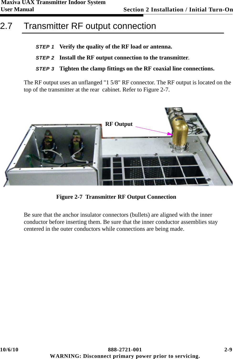
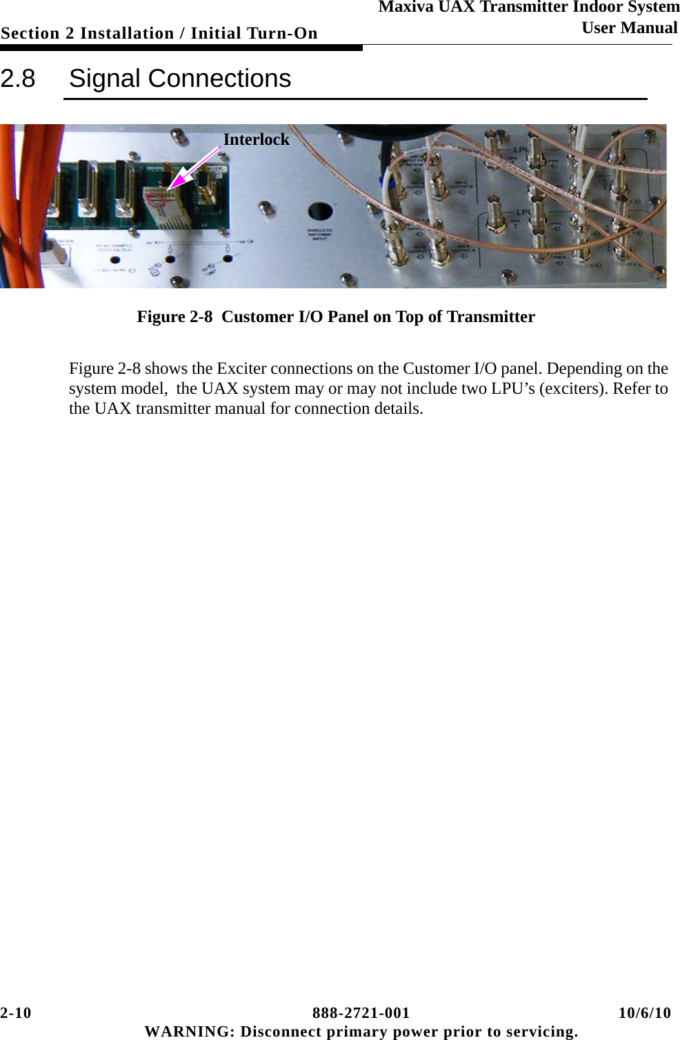
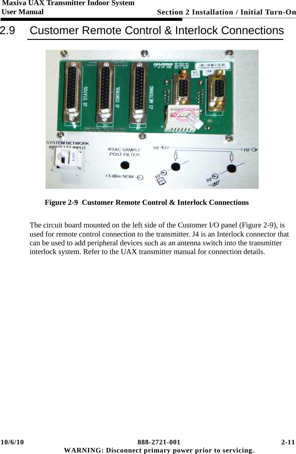
GatesAir UAXFLID Maxiva UAX Transmitter Indoor System User Manual 2721

GatesAir, Inc. Maxiva UAX Transmitter Indoor System 2721

Users Manual

Maxiva UAX Transmitter Indoor System888-2721-001Maxiva UAX Transmitter   Indoor System User ManualSeptember 29, 2010Rev: AT.M. No. 888-2721-001  © Copyright Harris Corporation 2010 All rights reserved
ii 888-2721-001 10/6/10 WARNING: Disconnect primary power prior to servicing.
10/6/10 888-2721-001 iii WARNING: Disconnect primary power prior to servicing.Technical AssistanceTechnical and troubleshooting assistance for HARRIS Transmission products is available from HARRIS Field Service (factory location: Quincy, Illinois, USA) during normal business hours (8:00 AM - 5:00 PM Central Time). Telephone +1-217-222-8200 to contact the Field Service Department; FAX +1-217-221-7086; or E-mail questions to tsupport@harris.com. Emergency service is available 24 hours a day, seven days a week, by telephone only.  On-line assistance, including technical manuals, white papers, software downloads, and service bulletins, is available at http://support.broadcast.harris.com/eservice_enu.  Address written correspondence to Field Service Department, HARRIS Broadcast Communications Division, P.O. Box 4290, Quincy, Illinois 62305-4290, USA. For other global service contact information, please visit: http://www.broadcast.harris.com/contact. NOTE: For all service and parts correspondence, you will need to provide the Sales Order number, as well as the Serial Number for the transmitter or part in question. For future reference, record those numbers here: ___________________/____________________ Please provide these numbers for any written request, or have these numbers ready in the event you choose to call regarding any Service, or Parts requests. For warranty claims it will be required, and for out of warranty products, this will help us to best identify what specific hardware was shipped.Replaceable Parts ServiceReplacement parts are available from HARRIS Service Parts Department from 7:00 AM to 11:00 PM Central Time, seven days a week. Telephone +1-217-222-8200 or email servicepartsreq@harris.com to contact the Service Parts Department.  Emergency replacement parts are available by telephone only, 24 hours a day, seven days a week by calling +1-217-222-8200.UnpackingCarefully unpack the equipment and preform a visual inspection to determine if any apparent damage was incurred during shipment. Retain the shipping materials until it has been verified that all equipment has been received undamaged. Locate and retain all PACKING CHECK LISTs. Use the PACKING CHECK LIST to help locate and identify any components or assemblies which are removed for shipping and must be reinstalled. Also remove any shipping supports, straps, and packing materials prior to initial turn on.Returns And ExchangesNo equipment can be returned unless written approval and a Return Authorization is received from HARRIS Broadcast Communications Division. Special shipping instructions and coding will be provided to assure proper handling. Complete details regarding circumstances and reasons for return are to be included in the request for return. Custom equipment or special order equipment is not returnable. In those instances where return or exchange of equipment is at the request of the customer, or convenience of the customer, a restocking fee will be charged. All returns will be sent freight prepaid and properly insured by the customer. When communicating with HARRIS Broadcast Communications Division, specify the HARRIS Order Number or Invoice Number.
iv 888-2721-001 10/6/10 WARNING: Disconnect primary power prior to servicing.
10/6/10 888-2721-001 MRH-1WARNING: Disconnect primary power prior to servicing.Manual Revision HistoryMaxiva UAX Transmitter Indoor System ManualREV. DATE ECN Pages Affected / Description2010 OCT Create manual.
MRH-2 888-2721-001 10/6/10 WARNING: Disconnect primary power prior to servicing.
10/6/10 888-2721-001 vii WARNING: Disconnect primary power prior to servicing.Guide to Using Harris Parts List InformationThe Harris Replaceable Parts List Index portrays a tree structure with the major items being leftmost in the index. The example below shows the Transmitter as the highest item in the tree structure. If you were to look at the bill of materials table for the Transmitter you would find the Control Cabinet, the PA Cabinet, and the Output Cabinet. In the Replaceable Parts List Index the Control Cabinet, PA Cabinet, and Output Cabinet show up one indentation level below the Transmitter and implies that they are used in the Transmitter. The Controller Board is indented one level below the Control Cabinet so it will show up in the bill of material for the Control Cabinet. The tree structure of this same index is shown to the right of the table and shows indentation level versus tree structure level.Example of Replaceable Parts List Index and equivalent tree structure:Replaceable Parts List Index               Part Number      Page Table 7-1.  Transmitter          994 9283 001  7-2 Table 7-2.     Control Cabinet          992 9244 002  7-3 Table 7-3.        Controller Board          992 8344 002  7-6 Table 7-4.     PA Cabinet          992 9400 002  7-7 Table 7-5.        PA Amplifier          994 7894 002  7-9 Table 7-6.          PA Amplifier Board      992 7904 002  7-10 Table 7-7.     Output Cabinet         992 9450 001   7-12The part number of the item is shown to the right of the description as is the page in the manual where the bill for that part number starts. Inside the actual tables, four main headings are used:•Table #-#. ITEM NAME - HARRIS PART NUMBER - this line gives the information that corresponds to the•Replaceable Parts List Index entry;•HARRIS P/N column gives the ten digit Harris part number (usually in ascending order);•DESCRIPTION column gives a 25 character or less description of the part number;•REF. SYMBOLS/EXPLANATIONS column 1) gives the reference designators for the item (i.e., C001, R102, etc.) that corresponds to the number found in the schematics (C001 in a bill of material is equiva-lent to C1 on the schematic) or 2) gives added information or further explanation (i.e., “Used for 208V operation only,” or “Used for HT 10LS only,” etc.).NOTE: Inside the individual tables some standard conventions are used:•A # symbol in front of a component such as #C001 under the REF. SYMBOLS/EXPLANATIONS col-umn means that this item is used on or with C001 and is not the actual part number for C001.•In the ten digit part numbers, if the last three numbers are 000, the item is a part that Harris has pur-chased and has not manufactured or modified. If the last three numbers are other than 000, the item is either manufactured by Harris or is purchased from a vendor and modified for use in the Harris product.•The first three digits of the ten digit part number tell which family the part number belongs to - for example, all electrolytic (can) capacitors will be in the same family (524 xxxx 000). If an electrolytic (can) capacitor is found to have a 9xx xxxx xxx part number (a number outside of the normal family of numbers), it has probably been modified in some manner at the Harris factory and will therefore show up farther down into the individual parts list (because each table is normally sorted in ascending order). Most Harris made or modified assemblies will have 9xx xxxx xxx numbers associated with them.The term “SEE HIGHER LEVEL BILL” in the description column implies that the reference designated part number will show up in a bill that is higher in the tree structure. This is often the case for components that may be frequency determinant or voltage determinant and are called out in a higher level bill structure that is more customer dependent than the bill at a lower level. Transmitter994 9283 001Control Cabinet 992 9244 002Controller Board 992 8344 002 PA Cabinet992 9400 002PA Amplifier992 7894 002PA Amplifier Board   992 7904 002Output Cabinet 992 9450 001
viii 888-2721-001 10/6/10 WARNING: Disconnect primary power prior to servicing.
10/6/10 888-2721-001 ix WARNING: Disconnect primary power prior to servicing.
x 888-2721-001 10/6/10 WARNING: Disconnect primary power prior to servicing.
10/6/10 888-2721-001 xi WARNING: Disconnect primary power prior to servicing.! WARNING:THE CURRENTS AND VOLTAGES IN THIS EQUIPMENT ARE DANGEROUS. PERSONNEL MUST AT ALL TIMES OBSERVE SAFETY WARNINGS, INSTRUC-TIONS AND REGULATIONS.This manual is intended as a general guide for trained and qualified personnel who are aware of the dangers inherent in handling potentially hazardous electrical/electronic circuits. It is not intended to contain a complete statement of all safety precautions which should be observed by personnel in using this or other electronic equipment.The installation, operation, maintenance and service of this equipment involves risks both to personnel and equipment, and must be performed only by qualified personnel exercising due care. HARRIS CORPORATION shall not be responsible for injury or damage resulting from improper procedures or from the use of improperly trained or inexperienced personnel performing such tasks. During installation and operation of this equipment, local building codes and fire protection standards must be observed.The following National Fire Protection Association (NFPA) standards are recommended as reference:- Automatic Fire Detectors, No. 72E- Installation, Maintenance, and Use of Portable Fire Extinguishers, No. 10- Halogenated Fire Extinguishing Agent Systems, No. 12A! WARNING:ALWAYS DISCONNECT POWER BEFORE OPENING COVERS, DOORS, ENCLO-SURES, GATES, PANELS OR SHIELDS. ALWAYS USE GROUNDING STICKS AND SHORT OUT HIGH VOLTAGE POINTS BEFORE SERVICING. NEVER MAKE INTERNAL ADJUSTMENTS, PERFORM MAINTENANCE OR SERVICE WHEN ALONE OR WHEN FATIGUED.Do not remove, short-circuit or tamper with interlock switches on access covers, doors, enclosures, gates, panels or shields. Keep away from live circuits, know your equipment and don’t take chances.! WARNING:IN CASE OF EMERGENCY ENSURE THAT POWER HAS BEEN DISCONNECTED.IF OIL FILLED OR ELECTROLYTIC CAPACITORS ARE UTILIZED IN YOUR EQUIPMENT, AND IF A LEAK OR BULGE IS APPARENT ON THE CAPACITOR CASE WHEN THE UNIT IS OPENED FOR SERVICE OR MAINTENANCE, ALLOW THE UNIT TO COOL DOWN BEFORE ATTEMPTING TO REMOVE THE DEFECTIVE CAPACITOR. DO NOT ATTEMPT TO SERVICE A DEFECTIVE CAPACITOR WHILE IT IS HOT DUE TO THE POSSIBILITY OF A CASE RUPTURE AND SUBSEQUENT INJURY.
xii 888-2721-001 10/6/10 WARNING: Disconnect primary power prior to servicing.
10/6/10 888-2721-001 xiii WARNING: Disconnect primary power prior to servicing.FIRST-AIDPersonnel engaged in the installation, operation, maintenance or servicing of this equipment are urged to become familiar with first-aid theory and practices. The following information is not intended to be complete first-aid procedures, it is a brief and is only to be used as a reference. It is the duty of all personnel using the equipment to be prepared to give adequate Emergency First Aid and there by prevent avoidable loss of life.Treatment of Electrical Burns1. Extensive burned and broken skina. Cover area with clean sheet or cloth. (Cleanest available cloth article.)b. Do not break blisters, remove tissue, remove adhered particles of clothing, or apply any salve or ointment.c. Treat victim for shock as required.d. Arrange transportation to a hospital as quickly as possible.e. If arms or legs are affected keep them elevated.NOTE:If medical help will not be available within an hour and the victim is conscious and not vomiting, give him a weak solution of salt and soda: 1 level teaspoonful of salt and 1/2 level teaspoonful of baking soda to each quart of water (neither hot or cold). Allow victim to sip slowly about 4 ounces (a half of glass) over a period of 15 minutes. Discontinue fluid if vomiting occurs. (Do not give alcohol.)2. Less severe burns - (1st & 2nd degree)a. Apply cool (not ice cold) compresses using the cleanest available cloth article.b. Do not break blisters, remove tissue, remove adhered particles of clothing, or apply salve or ointment.c. Apply clean dry dressing if necessary.d. Treat victim for shock as required.e. Arrange transportation to a hospital as quickly as possible.f. If arms or legs are affected keep them elevated.REFERENCE:ILLINOIS HEART ASSOCIATION AMERICAN RED CROSS STANDARD FIRST AID AND PERSONAL SAFETY MANUAL (SECOND EDITION)
xiv 888-2721-001 10/6/10 WARNING: Disconnect primary power prior to servicing.Glossary:ASI - Asynchronous serial interfaceBPF- Band pass filter. May also be called a mask filter, or  critical mask filer.CAN - Controller–area network (CAN or CAN-bus) is a vehicle bus standard designed to allow microcontrollers and devices to communicate with each other DAC - digital analog converterFPGA - Field programmable gate arrayGUI - graphical user interfaceHot-pluggable - device can be removed while transmitter is operating.HTML - HyperText Markup LanguageIRD - Integrated receiver decoderLCD - Liquid crystal displayLPF - Low pass filter. Typically located at the transmitter output port. Used to attenuate out of band emissions.LPU - Low power unit. Contains modulator and amplifier sections.MCM - Master control module (card in TCU)PA - Power amplifierPAB - Power amplifier blockPCM - Processor control module (card in TCU)PDU - Power distribution unitPS - Power supplyRF - Radio frequencyRS-485 -TIA/EIA standard for serial multipoint communications linesRTACTM - Real time adaptive correction
10/6/10 888-2721-001 xv WARNING: Disconnect primary power prior to servicing.Glossary Continued:SFN - Single frequency network  SMA - SMA connector consists of a 0.250x36 thread. The male is equipped with a .312 inch (7.925mm) hex nutTCU - Transmitter control unit.UDC - Up-down converterUPS - Uninterruptable power supplyVGA - Video graphics arrayWEB - A system of Internet servers that support HTML formatted documents.
xvi 888-2721-001 10/6/10 WARNING: Disconnect primary power prior to servicing.
Table of Contents 1Section 1IntroductionPurpose of This Manual  . . . . . . . . . . . . . . . . . . . .  1-1General Description. . . . . . . . . . . . . . . . . . . . . . . .  1-3System Block Diagrams . . . . . . . . . . . . . . . . . . . .  1-7System Specifications . . . . . . . . . . . . . . . . . . . . . .  1-8Environmental and Physical . . . . . . . . . . . . . . . .  1-8AC power . . . . . . . . . . . . . . . . . . . . . . . . . . . . . .  1-8Connectors . . . . . . . . . . . . . . . . . . . . . . . . . . . . .  1-8Section 2Installation /Initial Turn-OnIntroduction. . . . . . . . . . . . . . . . . . . . . . . . . . . . . .  2-1Documentation  . . . . . . . . . . . . . . . . . . . . . . . . . . .  2-1UAX Indoor System Drawings. . . . . . . . . . . . . .  2-2Cabinet Placement. . . . . . . . . . . . . . . . . . . . . . . . .  2-2Installation of Components Removed for Shipment2-4Install PA Modules . . . . . . . . . . . . . . . . . . . . . . .  2-4AC/Ground connections . . . . . . . . . . . . . . . . . . . .  2-7AC Distribution Panel. . . . . . . . . . . . . . . . . . . . . .  2-8Transmitter RF output connection. . . . . . . . . . . . .  2-9Signal Connections . . . . . . . . . . . . . . . . . . . . . . .  2-10Customer Remote Control & Interlock Connections2-11Initial Turn-On  . . . . . . . . . . . . . . . . . . . . . . . . . .  2-12Section 3Operation & MaintenanceIntroduction. . . . . . . . . . . . . . . . . . . . . . . . . . . . . .  3-1Transmitter Control Unit (TCU) . . . . . . . . . . . . . .  3-1Control Buttons overview: . . . . . . . . . . . . . . . . .  3-3Maintenance  . . . . . . . . . . . . . . . . . . . . . . . . . . . . .  3-4
Table of Contents2
10/6/10 888-2721-001 1-1 WARNING: Disconnect primary power prior to servicing.Maxiva UAX Transmitter Indoor System User ManualSection 1 Introduction 11.1 Purpose of This ManualThis User manual describes the UAX Indoor System utilizing the  UAX Maxiva transmitter. The contents of this manual address the location of system components, installaton requirements, initial turn-on steps, and overall system operation. Detailed information pertaining to the UAX Maxiva Transmitter is not included here, but can be found in a separate doc package (988-2693-004) included with the transmitter. Detailed information regarding individual system components can be found in the component documentation material supplied with this system. The various sections of this user manual provide the following types of information. Section 1, Introduction, provides equipment location information, block diagram and general specifications.Section 2, Installation/Initial Turn-On, provides cabinet hardware and electrical installation information for the transmitter system including: Cabinet placement, AC power connection, RF system connections, customer input connections, and remote interface connections.Section 3, Operation, provides general operation information for the system. Specific equipment operation information can be found in the technical manuals/pamphlets provided by the manufactures of the various components included in the enclosure system. Most of these can be found in a pouch inside the back door of the enclosure.
1-2 888-2721-001 10/6/10 WARNING: Disconnect primary power prior to servicing.Section 1 Introduction User ManualMaxiva UAX Transmitter Indoor SystemFigure 1-1  UAX 2 kW Indoor System - FrontAC DistributionPanelSat. Receiver & IRDRouterTCULPU BLPU APowerAmplifier2 kWMaskFilter UPSTransmitterPAB 1-4Blocks
10/6/10 888-2721-001 1-3 WARNING: Disconnect primary power prior to servicing.Section 1 Introduction Maxiva UAX Transmitter Indoor SystemUser Manual1.2 General DescriptionThis section contains equipment/hardware location information for the UAX Indoor System. Included in this section will be photos of the various components, physical location, interconnection, block diagram and system specifications. The UAX  Indoor System is a self contained transmission system designed to be installed indoors. The system includes the Harris solid state UAX  Transmitter and an on-board AC power distribution box. There are three models system models:•UAX2000FLS Indoor System  -2Kw RF Power Level with Single Exciter        •UAX2000FLD Indoor System  - 2Kw RF Power Level with Dual Exciters and Transmitter Control Unit                      •UAX1000FLS Indoor System-  1Kw RF Power Level with Single Exciter.   The transmitter cabinets utilize a rack mount system that accommodates additional peripheral equipment including a UPS unit, mask filter, router,  monitoring unit, and customer supplied satellite receivers, IRDs, etc.The self-contained system requires a stable/secure installation pad and external connections. The external connections include: 1. Proper grounding2. AC Mains ! WARNING:INSTALLATION OF THE AC MAINS AND GROUNDING MUST BE PERFORMED IN ACCORDANCE WITH ALL APPLICABLE CODES.3. Antenna coax4. Customer data stream input5. Remote control/monitoring Figure 1-2 shows the front of the enclosure system with the door open.
1-4 888-2721-001 10/6/10 WARNING: Disconnect primary power prior to servicing.Section 1 Introduction User ManualMaxiva UAX Transmitter Indoor SystemFigure 1-2  UAX Indoor Cabinet Rear View (door open)1-5/8" RF Outto AntennaPost FilterDirectional CouplerPre-FilterDirectionalCouplerPDU
10/6/10 888-2721-001 1-5 WARNING: Disconnect primary power prior to servicing.Section 1 Introduction Maxiva UAX Transmitter Indoor SystemUser ManualFigure 1-3  UAX Indoor Cabinet Rear View (without door)LPU BTCUReject LoadsFinal FilterOutputFilterFinal RejectLPU SwitchLPU LoadPDURF CombinerLoadUPSSplitterCombinerCombinerLPU A
1-6 888-2721-001 10/6/10 WARNING: Disconnect primary power prior to servicing.Section 1 Introduction User ManualMaxiva UAX Transmitter Indoor SystemFigure 1-4 shows the transmitter RF 1-5/8" flanged output connector.Figure 1-4  RF OutputFigure 1-4 also shows the customer interface panel mounted in the back of the transmitter cabinet. Refer to the UAX transmitter manual 888-2693-004 section 2.7 for detailed informationParallel Remote and InterlockConnectionsRF OutputCustomerI/O Panel
10/6/10 888-2721-001 1-7 WARNING: Disconnect primary power prior to servicing.Section 1 Introduction Maxiva UAX Transmitter Indoor SystemUser Manual1.3 System Block DiagramsFigure 1-5 is a simplified block diagram of the UAX indoor system RF transmission path.Figure 1-5  RF Transmission PathFigure 1-6 is a simplified block diagram of the communications path.Figure 1-6  Communications PathIRD (A)IRD (B)LPULPUI/O RF SwitchTCUPA BlockPA BlockPA BlockPA BlockFilterRF OutRouterT1IRD B IRD A Port ServerServerMonitor Interface PanelPunch Down PanelUPSAuto TransferSwitchModbus EthernetConverter (optional)Console
1-8 888-2721-001 10/6/10 WARNING: Disconnect primary power prior to servicing.Section 1 Introduction User ManualMaxiva UAX Transmitter Indoor System1.4 System SpecificationsThe following specifications refer to a typical 2kW outdoor enclosure system. Specifications are subject to change and may vary depending on system configuration.1.4.1 Environmental and PhysicalOperating Temperature (ambient): 0oC. to 40oC  Storage Temperature (ambient): -40oC to 70oC Humidity: 0 to 90% non-condensing.Altitude: Maximum 4,000 meters. Derate 2 degrees C. per 300m AMSL.Weight: Varies with model number. Consult system drawings.1.4.2 AC power Input voltage: 240V ±15% V, 60 Hz, single phase (transmitter)Input voltage: 120V ±15% V, 60 Hz, single phase (MSTS equipment)Nominal current at maximum RF output power: < 65A (transmitter)Nominal current at maximum RF output power: < 20A (MSTS equipment)Input Voltage Harmonics: < 5% THD1.4.3 ConnectorsTransmitter RF output:  EIA 1-5/8”, 50 OhmASI input:  BNC, female, 75 OhmNOTE:For warranty purposes, each major component in the system contains a bar code strip. These bar codes are NOT to be removed. See example shown in Figure 1-7.
10/6/10 888-2721-001 1-9 WARNING: Disconnect primary power prior to servicing.Section 1 Introduction Maxiva UAX Transmitter Indoor SystemUser ManualFigure 1-7  Component Barcode Identification
1-10 888-2721-001 10/6/10 WARNING: Disconnect primary power prior to servicing.Section 1 Introduction User ManualMaxiva UAX Transmitter Indoor System
10/6/10 888-2721-001 2-1 WARNING: Disconnect primary power prior to servicing.Maxiva UAX Transmitter Indoor SystemUser ManualSection 2 Installation / Initial Turn-On 22.1 IntroductionThis section includes the information necessary for installation and initial turn on of an UAX Indoor System.2.2 DocumentationFollowing is a partial list of documentation that ships with the system. Find and save all documentation. The top level Document Package numbers are shown below:UAX Transmitter Indoor System Doc Package: 988-2721-001UAX Indoor System, User Manual: 888-2721-001DWG Package, UAX Indoor System: 917-2323-240General Specifications, UAX Indoor System: 839-9363-264Diagram, Interconnect, UAX Indoor System: 839-9363-262UAX Indoor System Installation Manual: 888-2722-001UAX Indoor System Commissioning Manual: 888-2723-001The UAX Transmitter Document Package 988-2693-004 includes:UAX technical manual: 888-2693-004Drawing Package with a complete set of schematics for the transmitter System: 943-5276-170
2-2 888-2721-001 10/6/10 WARNING: Disconnect primary power prior to servicing.Section 2 Installation / Initial Turn-OnMaxiva UAX Transmitter Indoor SystemUser Manual2.2.1 UAX Indoor System DrawingsIt is recommended that you look through the documentation package to familiarize yourself with the information available. The installation and planning information is given in the following drawings: Wiring Diagram AC Distribution  - 843-5602-104 (in drawing package 943-5276-170) shows 208-240VAC wiring and has information on system current requirements.UAX Indoor System Interconnect Diagram - 839-9363-262 (in drawing package 917-2323-240) shows interconnect wiring between transmitter and all peripheral systems.2.3 Cabinet PlacementThe cabinet can be moved into position using a fork lift or a pallet jack. As an alternative the cabinet can be lifted in place using the four (4) lifting eye bolts supplied with the system. The eye bolts are shown in Figure 2-1. ! CAUTION:LIFT STRAIGHT UP, EVENLY FROM EACH LIFT POINT TO AVOID PLACING EXCESSUVE STRESS ON ANY ONE LIFT EYE. Figure 2-1  Lifting Eye Bolt
10/6/10 888-2721-001 2-3 WARNING: Disconnect primary power prior to servicing.Section 2 Installation / Initial Turn-On Maxiva UAX Transmitter Indoor SystemUser ManualSelect a cabinet location that allows adequate room in front and rear of transmitter to allow for removal of PA modules, opening of doors etc.The four (4) Lifting Eye bolts screw into the top of the transmitter cabinet. One in each corner. See Figure 2-2.Figure 2-2  Lifting Eye Bolt On Top of Transmitter CabinetSTEP 1 Install the lifting eyes. Be sure each lifting eye bolt is screwed all the way in. Tighten the bolts in place using a wrench handle or bar.STEP 2 Use an adequately sized hoist to lift the enclosure to its permanent location.STEP 3 Be sure the enclosure is level and securely positioned.STEP 4 Remove lifting eyes (optional).
2-4 888-2721-001 10/6/10 WARNING: Disconnect primary power prior to servicing.Section 2 Installation / Initial Turn-OnMaxiva UAX Transmitter Indoor SystemUser Manual2.4 Installation of Components Removed for ShipmentSelected components have been removed for shipment following factory assembly and test. These components have been packed separately and should be unpacked as needed for reassembly.  These items must be stored in a safe, climate controlled, dry location until needed for reassembly. Save all packing material until after commissioning to facilitate returns if needed. Notify Harris immediately if damage is noted while unloading the shipment.The removed components include:Removed from the front of the transmitter (and identified in Figure 1-2 on page 1-4) are two Satellite receivers and IRD’s, router, power amplifier modules in the LPU’s and power amplifier blocks, and the mask filter. Coaxial lines into and out of the mask filter may have been removed from the rear of the transmitter rack. STEP 1 Install the mask filter in the front of the cabinet and secure it in position.STEP 2 Install the power amplifier blocks in the LPU’s and in the power amplifier blocks. Read Section 2.4.1 Install PA Modules before installing PA modules.2.4.1 Install PA ModulesThe PA Modules should be placed into the Low Power Unit (LPU) and Power Amplifier Block (PAB) at this time. They should be inserted into the module slots in which they were tested. In the LPU the PA modules are inserted with the cooling fins up. Each module has a serial number which is recorded on the factory test data sheet as belonging to a specific module slot, in the LPU or specific PAB block. The module slots for each transmitter configuration are labeled as shown in Figure 2-3.
10/6/10 888-2721-001 2-5 WARNING: Disconnect primary power prior to servicing.Section 2 Installation / Initial Turn-On Maxiva UAX Transmitter Indoor SystemUser ManualFigure 2-3  LPU & PAB Numbering Front ViewPA modules in the PAB’s are installed in two orientations. The upper modules are installed with the cooling fins up. The lower PAB modules are installed with the cooling fins down. Fully seat each module by pressing firmly against the outside front edges on the handles. Do not press (or pull) on the center of the handle as it may deform.! CAUTION:IF THE MODULES DO NOT SEAT WITH MODERATE PRESSURE, REMOVE THE MODULE TO CHECK FOR INTERFERENCE. DO NOT FORCE THE MODULES INTO THE CHASSIS AS THIS MAY CAUSE DAMAGE TO THE RF CONNECTOR ON THE BACK OF THE MODULE OR ON THE PA BACKPLANE BOARD.STEP 3 Check the two satellite receivers and IRD units for security.STEP 4 Install the coaxial line assemblies at the input and output of the mask filter. STEP 5 Install the RF sample cables on the directional coupler located at the filter input. The location of these cables is described in the Wiring Diagram, UAX 2kW Dual Drive with TCU Racked, drawing number 843-5602-409 which can be found in the 917-2323-240 drawing package which is part of the 988-2693-004 documentation package.
2-6 888-2721-001 10/6/10 WARNING: Disconnect primary power prior to servicing.Section 2 Installation / Initial Turn-OnMaxiva UAX Transmitter Indoor SystemUser Manual! CAUTION:CARE MUST BE TAKEN TO PROPERLY CONNECT THESE CABLES IN THEIR PROPER LOCATION ON THE FORWARD OR REVERSE PORTS OF THE COUPLER. FAILURE TO HOOK THEM UP PROPERLY WILL RESULT IN POOR PERFORMANCE OR FAILURE.STEP 6 Check the network router and cable connections for security.STEP 7 Using the indoor system interconnect drawing and the UAX wiring diagram connect all input and outputs to the installed components.
10/6/10 888-2721-001 2-7 WARNING: Disconnect primary power prior to servicing.Section 2 Installation / Initial Turn-On Maxiva UAX Transmitter Indoor SystemUser Manual2.5 AC/Ground connectionsThere are two AC power connections needed for the UAX Indoor System. 208-240VAC is required and connected inside the AC access panel shown in Figure 2-4. See the AC wiring diagram843-5602-148 in the UAX drawing package 943-5276-170.Figure 2-4  UAX AC Mains Connections (top of cabinet, access panel cover removed)An additional 120VAC connection (L1, N & ground) is required at the distribution box on the top of the transmitter. The connection is made at the side of the box with 1/2" conduit fittings supplied by thecustomer. The distribution box is shown in Figure 2-5.Figure 2-5  120VAC Connection208-240VACInputSafetyGround AC ConnectionsACInput120VACDistribution Box120VAC
2-8 888-2721-001 10/6/10 WARNING: Disconnect primary power prior to servicing.Section 2 Installation / Initial Turn-OnMaxiva UAX Transmitter Indoor SystemUser Manual2.6 AC Distribution Panel! CAUTION:ALL CONNECTIONS LISTED IN THIS SECTION SHOULD BE VERIFIED WITH THE SCHEMATICS BEFORE INITIAL TURN ON.! CAUTION:THE USE OF A SYSTEM SURGE SUPPRESSOR IS RECOMMENDED. THE SYSTEM SURGE SUPPRESSOR WILL BE PROVIDED BY THE CUSTOMER.Figure 2-6  Transmitter AC Distribution PanelFigure 2-6 shows the AC distribution panel. LPU, TCU and PAB power can be controlled from this panel. It is located at the top of the transmitter in the front.STEP 1 Verify all circuit breakers on the AC distribution panel in the transmitter cabinet are OFF. STEP 2 Verify that the AC mains are disabled before proceeding.STEP 3 Connect a safety ground cable from the ground connector shown in Figure 2-4 to the AC mains ground.  STEP 4 Following all local codes hook up the 208-240 and 120VAC mains.
10/6/10 888-2721-001 2-9 WARNING: Disconnect primary power prior to servicing.Section 2 Installation / Initial Turn-On Maxiva UAX Transmitter Indoor SystemUser Manual2.7 Transmitter RF output connectionSTEP 1 Verify the quality of the RF load or antenna. STEP 2 Install the RF output connection to the transmitter.STEP 3 Tighten the clamp fittings on the RF coaxial line connections.The RF output uses an unflanged "1 5/8" RF connector. The RF output is located on the top of the transmitter at the rear  cabinet. Refer to Figure 2-7.  Figure 2-7  Transmitter RF Output ConnectionBe sure that the anchor insulator connectors (bullets) are aligned with the inner conductor before inserting them. Be sure that the inner conductor assemblies stay centered in the outer conductors while connections are being made.RF Output
2-10 888-2721-001 10/6/10 WARNING: Disconnect primary power prior to servicing.Section 2 Installation / Initial Turn-OnMaxiva UAX Transmitter Indoor SystemUser Manual2.8 Signal ConnectionsFigure 2-8  Customer I/O Panel on Top of TransmitterFigure 2-8 shows the Exciter connections on the Customer I/O panel. Depending on the system model,  the UAX system may or may not include two LPU’s (exciters). Refer to the UAX transmitter manual for connection details. Interlock
10/6/10 888-2721-001 2-11 WARNING: Disconnect primary power prior to servicing.Section 2 Installation / Initial Turn-On Maxiva UAX Transmitter Indoor SystemUser Manual2.9 Customer Remote Control & Interlock ConnectionsFigure 2-9  Customer Remote Control & Interlock ConnectionsThe circuit board mounted on the left side of the Customer I/O panel (Figure 2-9), is used for remote control connection to the transmitter. J4 is an Interlock connector that can be used to add peripheral devices such as an antenna switch into the transmitter interlock system. Refer to the UAX transmitter manual for connection details.
2-12 888-2721-001 10/6/10 WARNING: Disconnect primary power prior to servicing.Section 2 Installation / Initial Turn-OnMaxiva UAX Transmitter Indoor SystemUser Manual2.10 Initial Turn-OnRead and understand the entire initial turn-on procedure before starting. Descriptions and operational instructions for TCU and LPU GUI screens is given in Section 3 "Operation" in the UAX Transmitter manual.STEP 1 Make sure the output RF line is connected properly. If connecting to a load, verify the load connections are proper and that load conditions are met. ! CAUTION:THE TRANSMITTER RF LINE MUST BE CONNECTED TO A KNOWN GOOD LOAD OR ANTENNA. IF THE CONDITION OF THE LOAD OR ANTENNA ARE IN DOUBT THEY SHOULD BE MEASURED WITH A NETWORK ANALYZER PRIOR TO TURNING ON THE TRANSMITTER.STEP 2 Verify all ground connections are secure and the AC power feed connections from the facility AC power source are tight and of proper capacity (correct gauge wire, breaker size etc.).STEP 3 Verify the AC access cover is properly installed on the top of the transmitter.  STEP 4 Check the transmitter cabinet for any loose hardware. Visually inspect that all cable/wire/cord connections are secure.STEP 5 Check that all AC mains breakers for the transmitter system are OFF. All circuit  breakers on the AC distribution panel at the top front  of the transmitter cabinet should also be OFF.STEP 6 Apply AC primary power to the enclosure system. Be ready to quickly disconnect the power if necessary.STEP 7 If the system has a UPS unit, it must be turned ON to power the rest of the system. Check the UPS manufacturer’s manual for procedure. STEP 8 To turn the Transmitter on, refer to the procedure in the Transmitter manual. It begins by turning each of the transmitter breakers ON. These are the breakers in the breaker panel at the top of the transmitter.  Only the transmitter is connected to these breakers.STEP 9 After the Transmitter is turned ON, verify power out is correct on the TCU Home Screen. Refer to the transmitter manual for detailed operation of all transmitter functions and operation.
10/6/10 888-2721-001 2-13 WARNING: Disconnect primary power prior to servicing.Section 2 Installation / Initial Turn-On Maxiva UAX Transmitter Indoor SystemUser ManualNOTE:Make sure the transmission data stream is being fed into the exciter. If not, the transmitter will stay in a Mute condition and will not produce RF. STEP 10 Some individual pieces of equipment (non-supplied equipment - computer, satellite receivers etc.) may require turning individual power switches on.  Check the owner’s manual for each piece for turn-on procedure.  STEP 11 Check the equipment mounted in the front  of the transmitter rack (receivers,  router, etc.) to verify all is powered up. NOTE:Equipment should power up automatically when the breakers are turned ON. The indoor system is designed so that breakers activate all equipment.At this time, the TCU and Home screen should appear as shown in Figure 2-10. All LEDs should be illuminated GREEN. If any are RED, refer to the Transmitter manual for detailed information. Actual forward power can be read off the top bar graph.Figure 2-10  Transmitter TCU Screen and ControlsThis completes the initial Turn-On procedure. Do a visual inspection of the entire system to verify the system is operating properly, verify the RF connections are secure, and confirm the Air Conditioning unit is operating and cooling the enclosure. STEP 12  Close all doors and secure them before leaving.
2-14 888-2721-001 10/6/10 WARNING: Disconnect primary power prior to servicing.Section 2 Installation / Initial Turn-OnMaxiva UAX Transmitter Indoor SystemUser ManualNOTE:The UAX transmitter cabinet door contains an integrated handel and  key lock.  See Figure Figure 2-11. Two keys ship with the transmitter and are hanging  inside the cabinet. The handle can be lifted upward and then twisted CCW to open the rear door. Figure 2-11  Enclosure Door Lock
10/6/10 888-2721-001 3-1 WARNING: Disconnect primary power prior to servicing.Maxiva UAX Transmitter Indoor SystemUser ManualSection 3 Operation & Maintenance 33.1 IntroductionThis section provides operational information for the UAX Transmitter Indoor SystemNOTE:Operation of the UAX Transmitter and the LPU (low power unit) is covered in a separate manual which ships with the system.3.2 Transmitter Control Unit (TCU)The TCU front panel user interface utilizes a 1/4 VGA, LCD touchscreen display. See Figure 3-1. This touchscreen display uses software buttons to monitor the transmitter. There are 12 hardware buttons for the primary transmitter functions shown in Transmitter Control Panel. Refer to the UAX Transmitter Manual 888-2693-004 for details.  The TCU Home screen shows the total output power of the transmitter before the output filter. Note that no VSWR is displayed. The VSWR is read off the LPU (low power unit....Exciter) screens.
3-2 888-2721-001 10/6/10 WARNING: Disconnect primary power prior to servicing.Section 3 Operation & MaintenanceMaxiva UAX Transmitter Indoor SystemUser ManualFigure 3-1  Transmitter TCU ScreenFigure 3-2  Transmitter Control Panel
10/6/10 888-2721-001 3-3 WARNING: Disconnect primary power prior to servicing.Section 3 Operation & Maintenance Maxiva UAX Transmitter Indoor SystemUser Manual3.2.1 Control Buttons overview:•TRANSMITTER "ON" and "OFF" (the main transmitter on/off buttons, also used as a reset button for latching faults)•POWER "Raise" and "Lower" (to raise or lower transmitter output power)•POWER CONTROL "Auto" and "Man" (for automatic or manual output power con-trol) to raise or lower the transmitter power, press Raise or Lower to adjust output power. Once the output power has been set to the desired level, that level will be automatically maintained if the power control is set to Auto.•DRIVE "A" and "B" (To choose Drive Chain A or Drive Chain B) •DRIVE CONTROL "Auto" and "Man" (In "Manual" mode, operator can select Drive Chain A or B. In "Auto" mode, the TCU will automatically switch drive chains if a fault occurs in the active drive chain.•REMOTE "Enable" and "Disable" (To block all remote control operations of the transmitter). By pressing the "Disable" button, prevents a remote control operator from performing any transmitter function while a local operator/engineer is perform-ing tests or maintenance on the transmitter. NOTE:Be sure to press the "Enable" button before leaving the transmitter facility. When leaving the enclosure facility check to make sure the control buttons are lit as follows:•POWER CONTROL: Auto•DRIVE: A•DRIVE CONTROL: Auto•REMOTE: Enable•TRANSMITTER: ONSee Figure 3-3 which shows the front of the router. The Console Command Port on the front of the router allows the server to set/program the parameters of the system. Also note the power switch is also located on the front of the router.
3-4 888-2721-001 10/6/10 WARNING: Disconnect primary power prior to servicing.Section 3 Operation & MaintenanceMaxiva UAX Transmitter Indoor SystemUser Manual Figure 3-3  Router Front View3.3 MaintenanceThis section contains the maintenance procedures for the UAX Transmitter Indoor System. Always refer to the manufacturer’s manual of the individual components for specific maintenance procedures.The indoor system requires very little maintenance. The filters in the front of the PABs and LPUs should be checked and cleaned periodically. If the enclosure is exposed to high levels of dust and dirt, cleaning should occur more often. Simply remove the filters and wash them out using water. Dry the filters before reinstalling them.See Section 5 in the UAX transmitter technical manual (888-2693-004) for detailed maintenance and service information.Console Port Power On/Off

Navigation menu