GatesAir ULXATSC Maxiva ULX ATSC Series Digital Transmitter User Manual 2715
GatesAir, Inc. Maxiva ULX ATSC Series Digital Transmitter 2715
GatesAir >
Manual

Maxiva ULX ATSC Series
Digital Transmitter
User MANUAL
888-2715-001
Maxiva ULX ATSC Series
Digital Transmitter
February 19, 2010
Rev: A
T.M. No. 888-2715-001
© Copyright Harris Corporation 2010
All rights reserved

ii 888-2715-001 2/19/10
WARNING: Disconnect primary power prior to servicing.

2/19/10 888-2715-001 iii
WARNING: Disconnect primary power prior to servicing.
Technical Assistance
Technical and troubleshooting assistance for HARRIS Transmission products is available from
HARRIS Field Service (factory location: Quincy, Illinois, USA) during normal business hours (8:00
AM - 5:00 PM Central Time). Telephone +1-217-222-8200 to contact the Field Service Department;
FAX +1-217-221-7086; or E-mail questions to tsupport@harris.com.
Emergency service is available 24 hours a day, seven days a week, by telephone only.
On-line assistance, including technical manuals, white papers, software downloads, and service
bulletins, is available at http://support.broadcast.harris.com/eservice_enu.
Address written correspondence to Field Service Department, HARRIS Broadcast Communications
Division, P.O. Box 4290, Quincy, Illinois 62305-4290, USA. For other global service contact
information, please visit: http://www.broadcast.harris.com/contact.
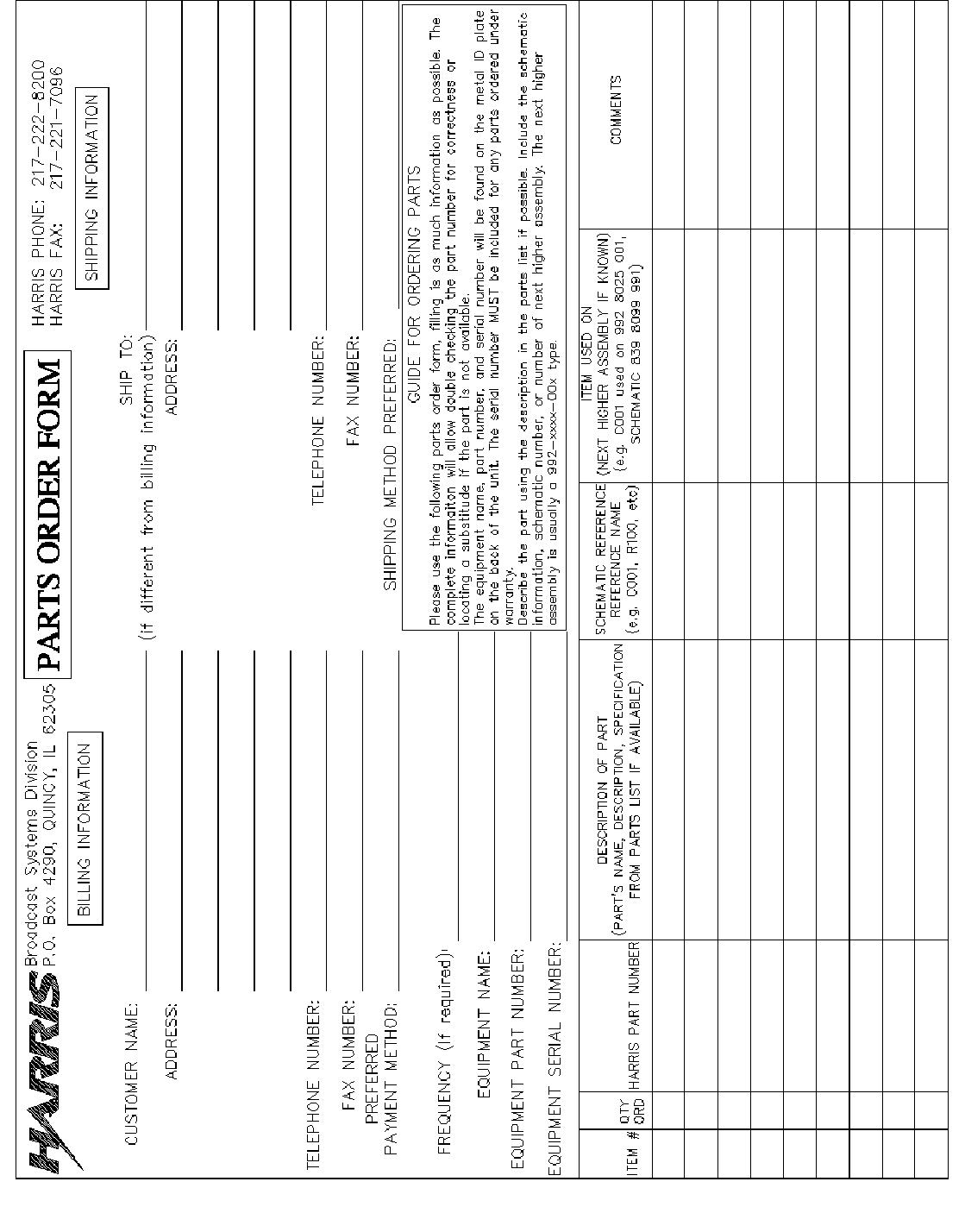
NOTE: For all service and parts correspondence, you will need to provide the Sales Order number,
as well as the Serial Number for the transmitter or part in question. For future reference, record those
numbers here: ___________________/____________________
Please provide these numbers for any written request, or have these numbers ready in the event you
choose to call regarding any Service, or Parts requests. For warranty claims it will be required, and
for out of warranty products, this will help us to best identify what specific hardware was shipped.
Replaceable Parts Service
Replacement parts are available from HARRIS Service Parts Department from 7:00 AM to 11:00 PM
Central Time, seven days a week. Telephone +1-217-222-8200 or email servicepartsreq@harris.com
to contact the Service Parts Department.
Emergency replacement parts are available by telephone only, 24 hours a day, seven days a week
by calling +1-217-222-8200.
Unpacking
Carefully unpack the equipment and preform a visual inspection to determine if any apparent damage
was incurred during shipment. Retain the shipping materials until it has been verified that all
equipment has been received undamaged. Locate and retain all PACKING CHECK LISTs. Use the
PACKING CHECK LIST to help locate and identify any components or assemblies which are
removed for shipping and must be reinstalled. Also remove any shipping supports, straps, and
packing materials prior to initial turn on.
Returns And Exchanges
No equipment can be returned unless written approval and a Return Authorization is received from
HARRIS Broadcast Communications Division. Special shipping instructions and coding will be
provided to assure proper handling. Complete details regarding circumstances and reasons for return
are to be included in the request for return. Custom equipment or special order equipment is not
returnable. In those instances where return or exchange of equipment is at the request of the
customer, or convenience of the customer, a restocking fee will be charged. All returns will be sent
freight prepaid and properly insured by the customer. When communicating with HARRIS Broadcast
Communications Division, specify the HARRIS Order Number or Invoice Number.

iv 888-2715-001 2/19/10
WARNING: Disconnect primary power prior to servicing.

2/19/10 888-2715-001 MRH-1
WARNING: Disconnect primary power prior to servicing.
Manual Revision History
Maxiva ULX ATSC Series Digital Transmitter User Manual
REV. DATE ECN Pages Affected
AFEB 2010 -Created

MRH-2 888-2715-001 2/19/10
WARNING: Disconnect primary power prior to servicing.
2/19/10 888-2715-001 vii
WARNING: Disconnect primary power prior to servicing.
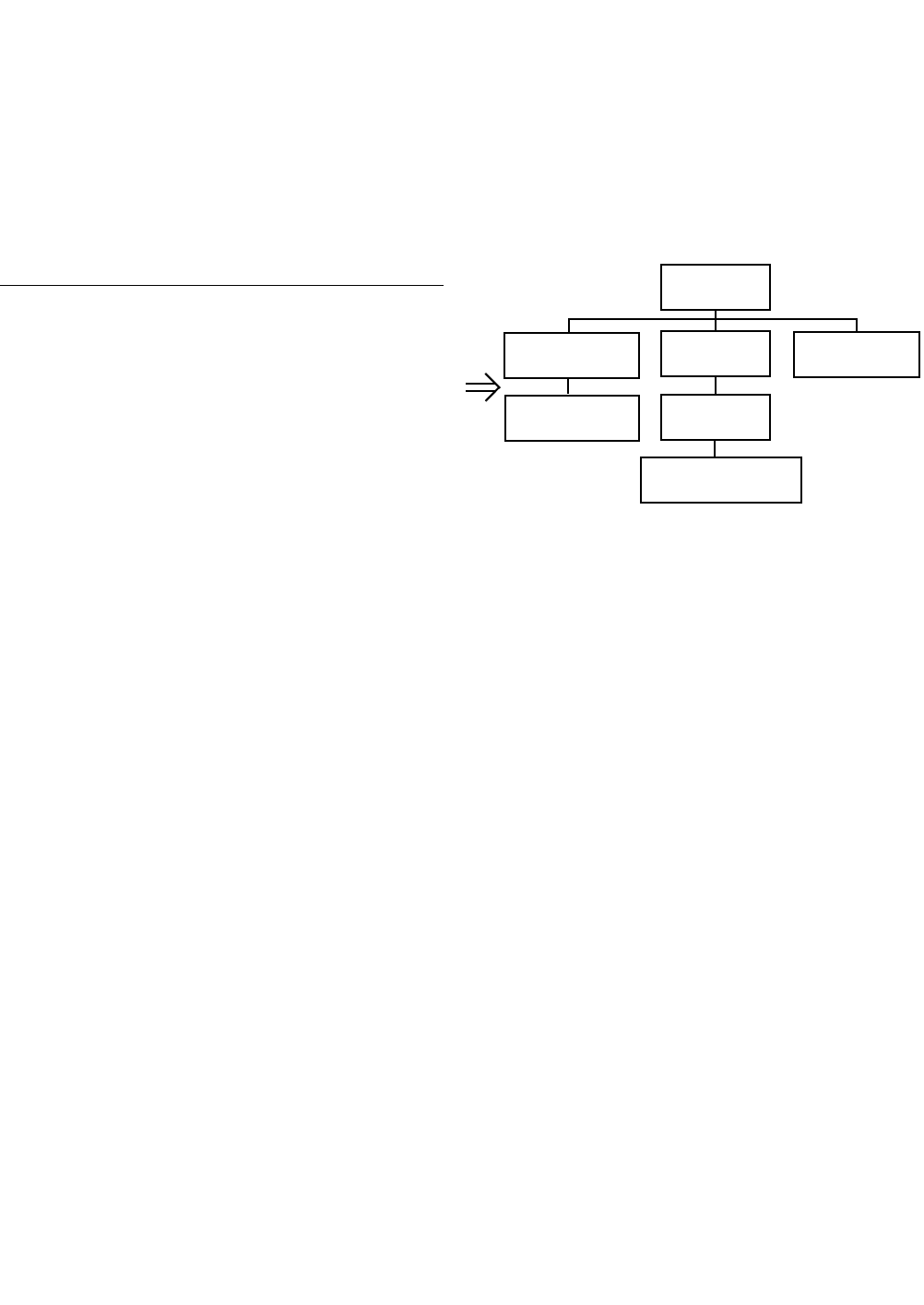
Guide to Using Harris Parts List Information
The Harris Replaceable Parts List Index portrays a tree structure with the major items being leftmost in the index.
The example below shows the Transmitter as the highest item in the tree structure. If you were to look at the bill
of materials table for the Transmitter you would find the Control Cabinet, the PA Cabinet, and the Output
Cabinet. In the Replaceable Parts List Index the Control Cabinet, PA Cabinet, and Output Cabinet show up one
indentation level below the Transmitter and implies that they are used in the Transmitter. The Controller Board is
indented one level below the Control Cabinet so it will show up in the bill of material for the Control Cabinet.
The tree structure of this same index is shown to the right of the table and shows indentation level versus tree
structure level.
Example of Replaceable Parts List Index and equivalent tree structure:
Replaceable Parts List Index Part Number Page
Table 7-1. Transmitter 994 9283 001 7-2
Table 7-2. Control Cabinet 992 9244 002 7-3
Table 7-3. Controller Board 992 8344 002 7-6
Table 7-4. PA Cabinet 992 9400 002 7-7
Table 7-5. PA Amplifier 994 7894 002 7-9
Table 7-6. PA Amplifier Board 992 7904 002 7-10
Table 7-7. Output Cabinet 992 9450 001 7-12
The part number of the item is shown to the right of the description as is the page in the manual where the bill for
that part number starts. Inside the actual tables, four main headings are used:
•Table #-#. ITEM NAME - HARRIS PART NUMBER - this line gives the information that corresponds
to the Replaceable Parts List Index entry;
•HARRIS P/N column gives the ten digit Harris part number (usually in ascending order);
•DESCRIPTION column gives a 25 character or less description of the part number;
•REF. SYMBOLS/EXPLANATIONS column 1) gives the reference designators for the item (i.e., C001,
R102, etc.) that corresponds to the number found in the schematics (C001 in a bill of material is equiva-
lent to C1 on the schematic) or 2) gives added information or further explanation (i.e., “Used for 208V
operation only,” or “Used for HT 10LS only,” etc.).
NOTE: Inside the individual tables some standard conventions are used:
•A # symbol in front of a component such as #C001 under the REF. SYMBOLS/EXPLANATIONS col-
umn means that this item is used on or with C001 and is not the actual part number for C001.
•In the ten digit part numbers, if the last three numbers are 000, the item is a part that Harris has pur-
chased and has not manufactured or modified. If the last three numbers are other than 000, the item is
either manufactured by Harris or is purchased from a vendor and modified for use in the Harris product.
•The first three digits of the ten digit part number tell which family the part number belongs to - for
example, all electrolytic (can) capacitors will be in the same family (524 xxxx 000). If an electrolytic
(can) capacitor is found to have a 9xx xxxx xxx part number (a number outside of the normal family of
numbers), it has probably been modified in some manner at the Harris factory and will therefore show
up farther down into the individual parts list (because each table is normally sorted in ascending order).
Most Harris made or modified assemblies will have 9xx xxxx xxx numbers associated with them.
The term “SEE HIGHER LEVEL BILL” in the description column implies that the reference designated part
number will show up in a bill that is higher in the tree structure. This is often the case for components
that may be frequency determinant or voltage determinant and are called out in a higher level bill
structure that is more customer dependent than the bill at a lower level.
Transmitter
994 9283 001
Control Cabinet
992 9244 002
Controller Board
992 8344 002
PA Cabinet
992 9400 002
PA Amplifier
992 7894 002
PA Amplifier Board
992 7904 002
Output Cabinet
992 9450 001

viii 888-2715-001 2/19/10
WARNING: Disconnect primary power prior to servicing.
2/19/10 888-2715-001 ix
WARNING: Disconnect primary power prior to servicing.

x 888-2715-001 2/19/10
WARNING: Disconnect primary power prior to servicing.

2/19/10 888-2715-001 xi
WARNING: Disconnect primary power prior to servicing.
! WARNING:
TTHE CURRENTS AND VOLTAGES IN THIS EQUIPMENT ARE DANGEROUS.
PERSONNEL MUST AT ALL TIMES OBSERVE SAFETY WARNINGS, INSTRUC-
TIONS AND REGULATIONS.
This manual is intended as a general guide for trained and qualified personnel who are aware
of the dangers inherent in handling potentially hazardous electrical/electronic circuits. It is not
intended to contain a complete statement of all safety precautions which should be observed
by personnel in using this or other electronic equipment.
The installation, operation, maintenance and service of this equipment involves risks both to
personnel and equipment, and must be performed only by qualified personnel exercising due
care. HARRIS CORPORATION shall not be responsible for injury or damage resulting from
improper procedures or from the use of improperly trained or inexperienced personnel
performing such tasks. During installation and operation of this equipment, local building
codes and fire protection standards must be observed.
The following National Fire Protection Association (NFPA) standards are recommended as
reference:
- Automatic Fire Detectors, No. 72E
- Installation, Maintenance, and Use of Portable Fire Extinguishers, No. 10
- Halogenated Fire Extinguishing Agent Systems, No. 12A
! WARNING:
ALWAYS DISCONNECT POWER BEFORE OPENING COVERS, DOORS, ENCLO-
SURES, GATES, PANELS OR SHIELDS. ALWAYS USE GROUNDING STICKS
AND SHORT OUT HIGH VOLTAGE POINTS BEFORE SERVICING. NEVER MAKE
INTERNAL ADJUSTMENTS, PERFORM MAINTENANCE OR SERVICE WHEN
ALONE OR WHEN FATIGUED.
Do not remove, short-circuit or tamper with interlock switches on access covers, doors,
enclosures, gates, panels or shields. Keep away from live circuits, know your equipment and
don’t take chances.
! WARNING:
IN CASE OF EMERGENCY ENSURE THAT POWER HAS BEEN DISCONNECTED.
! WARNING:
IF OIL FILLED OR ELECTROLYTIC CAPACITORS ARE UTILIZED IN YOUR
EQUIPMENT, AND IF A LEAK OR BULGE IS APPARENT ON THE CAPACITOR
CASE WHEN THE UNIT IS OPENED FOR SERVICE OR MAINTENANCE, ALLOW
THE UNIT TO COOL DOWN BEFORE ATTEMPTING TO REMOVE THE DEFEC-
TIVE CAPACITOR. DO NOT ATTEMPT TO SERVICE A DEFECTIVE CAPACITOR
WHILE IT IS HOT DWHILE IT IS HOT DUE TO THE POSSIBILITY OF A CASE RUP-
TURE AND SUBSEQUENT INJURY.

xii 888-2715-001 2/19/10
WARNING: Disconnect primary power prior to servicing.

2/19/10 888-2715-001 xiii
WARNING: Disconnect primary power prior to servicing.
FIRST-AID
Personnel engaged in the installation, operation, maintenance or servicing of this equipment
are urged to become familiar with first-aid theory and practices. The following information is
not intended to be complete first-aid procedures, it is a brief and is only to be used as a
reference. It is the duty of all personnel using the equipment to be prepared to give adequate
Emergency First Aid and there by prevent avoidable loss of life.
Treatment of Electrical Burns
1. Extensive burned and broken skin
a. Cover area with clean sheet or cloth. (Cleanest available cloth
article.)
b. Do not break blisters, remove tissue, remove adhered particles of
clothing, or apply any salve or ointment.
c. Treat victim for shock as required.
d. Arrange transportation to a hospital as quickly as possible.
e. If arms or legs are affected keep them elevated.
NOTE:
If medical help will not be available within an hour and the victim is conscious and
not vomiting, give him a weak solution of salt and soda: 1 level teaspoonful of salt
and 1/2 level teaspoonful of baking soda to each quart of water (neither hot or
cold). Allow victim to sip slowly about 4 ounces (a half of glass) over a period of
15 minutes. Discontinue fluid if vomiting occurs. (Do not give alcohol.)
2. Less severe burns - (1st & 2nd degree)
a. Apply cool (not ice cold) compresses using the cleanest available
cloth article.
b. Do not break blisters, remove tissue, remove adhered particles of
clothing, or apply salve or ointment.
c. Apply clean dry dressing if necessary.
d. Treat victim for shock as required.
e. Arrange transportation to a hospital as quickly as possible.
f. If arms or legs are affected keep them elevated.
REFERENCE:
ILLINOIS HEART ASSOCIATION
AMERICAN RED CROSS STANDARD FIRST AID AND PERSONAL SAFETY
MANUAL (SECOND EDITION)

xiv 888-2715-001 2/19/10
WARNING: Disconnect primary power prior to servicing.

Table of Contents
1
Section 1
Introduction
Purpose of This Manual . . . . . . . . . . . . . . . . . . . . 1-1
General Description. . . . . . . . . . . . . . . . . . . . . . . . 1-2
Maxiva ATSC Series Transmitter Models . . . . . 1-4
System Block Diagram. . . . . . . . . . . . . . . . . . . . 1-4
Transmitter Control System . . . . . . . . . . . . . . . . 1-5
Transmitter RF Power Control . . . . . . . . . . . . . . 1-7
Graphical User Interface . . . . . . . . . . . . . . . . . . . . . .1-7
Control System Communications. . . . . . . . . . . . 1-7
Software Updates. . . . . . . . . . . . . . . . . . . . . . . . . . . .1-8
Remote Control . . . . . . . . . . . . . . . . . . . . . . . . . . . . .1-8
PA Module . . . . . . . . . . . . . . . . . . . . . . . . . . . . . 1-8
Module Control . . . . . . . . . . . . . . . . . . . . . . . . . . . .1-12
Transmitter Power Supplies . . . . . . . . . . . . . . . 1-13
Cooling System. . . . . . . . . . . . . . . . . . . . . . . . . 1-13
Cooling System Control Panel . . . . . . . . . . . . . . . .1-15
Pump Module/Heat Exchanger . . . . . . . . . . . . . . . .1-18
Heat Exchanger Fan Control. . . . . . . . . . . . 1-19
Pump Operation/Control Logic. . . . . . . . . . 1-19
PA Module and Combiner Cold Plates . . . . . . . . . .1-20
M2X Multimedia Exciter . . . . . . . . . . . . . . . . . 1-22
General Specifications. . . . . . . . . . . . . . . . . . . . . 1-23
Section 2
Operation
Introduction. . . . . . . . . . . . . . . . . . . . . . . . . . . . . . 2-1
Transmitter Control Panel . . . . . . . . . . . . . . . . . . . 2-1
Hardware Control Buttons . . . . . . . . . . . . . . . . . 2-2
Graphical User Interface (GUI). . . . . . . . . . . . . . . 2-4
Global Status and Navigation. . . . . . . . . . . . . . . 2-4
GUI Home Screen. . . . . . . . . . . . . . . . . . . . . . . . . 2-7
Drive Chain Main Menu . . . . . . . . . . . . . . . . . . . . 2-9
Drive Chain Faults . . . . . . . . . . . . . . . . . . . . . . 2-10
Drive Chain Meters . . . . . . . . . . . . . . . . . . . . . 2-11
Power Amp Main Menu . . . . . . . . . . . . . . . . . . . 2-13
PA Faults. . . . . . . . . . . . . . . . . . . . . . . . . . . . . . 2-14
Output Main Screen . . . . . . . . . . . . . . . . . . . . . . 2-15
Output Faults . . . . . . . . . . . . . . . . . . . . . . . . . . 2-16
Power Supply Main Menu. . . . . . . . . . . . . . . . . . 2-17
PS Faults. . . . . . . . . . . . . . . . . . . . . . . . . . . . . . 2-18
System Main Menu . . . . . . . . . . . . . . . . . . . . . . . 2-19
System Faults . . . . . . . . . . . . . . . . . . . . . . . . . . 2-20
System Fault Log . . . . . . . . . . . . . . . . . . . . . . . 2-20
System Service . . . . . . . . . . . . . . . . . . . . . . . . . 2-22
Admin Setup (Local GUI Only) . . . . . . . . . . . . . . .2-23
System Setup . . . . . . . . . . . . . . . . . . . . . . . . . . . . . .2-24
Cabinet Setup. . . . . . . . . . . . . . . . . . . . . . . . . . . . . .2-25
System and Cabinet Power Calibrate . . . . . . . . . . .2-26
System Version Screen . . . . . . . . . . . . . . . . . . . . . .2-26
System Network Screen . . . . . . . . . . . . . . . . . . . . .2-27
GUI Menu Structures . . . . . . . . . . . . . . . . . . . . . .2-28
Section 3
Diagnostics
Introduction. . . . . . . . . . . . . . . . . . . . . . . . . . . . . . .3-1
GUI System Log . . . . . . . . . . . . . . . . . . . . . . . . . . .3-2
Maxiva Three-Strike Fault Actions. . . . . . . . . . . . .3-3
Reflected Power Faults. . . . . . . . . . . . . . . . . . . . .3-3
Module Faults. . . . . . . . . . . . . . . . . . . . . . . . . . . .3-3
Fault Tables. . . . . . . . . . . . . . . . . . . . . . . . . . . . . . .3-5

Table of Contents
2

2/19/10 888-2715-001 1-1
WARNING: Disconnect primary power prior to servicing.
Maxiva ULX ATSC Series
User Manual
Section 1
Introduction 1
1.1 Purpose of This Manual
This user manual contains the information pertaining to the Maxiva ULX Series, solid-
state, UHF, ATSC digital TV transmitter. The various sections of this technical manual
provide the following types of information.
•Section 1, Introduction, provides general manual layout, photos, equipment descrip-
tion, block diagram and general specifications.
•Section 2, Operation, provides operation and navigation information for the Graphi-
cal User Interface or GUI as well as identification and functions of all external panel
controls and indicators.
•Section 3, Diagnostics, provides detailed fault information and diagnostic procedures
to the board level.
1-2 888-2715-001 2/19/10
WARNING: Disconnect primary power prior to servicing.
Section 1 Introduction
Maxiva ULX ATSC Series
User Manual
1.2 General Description
This section contains a general description of the Maxiva ULX Series ATSC digital
television transmitters. Included in this section will be descriptions of the Control
System, Power Amplifier, block diagrams of the different models and system
specifications.
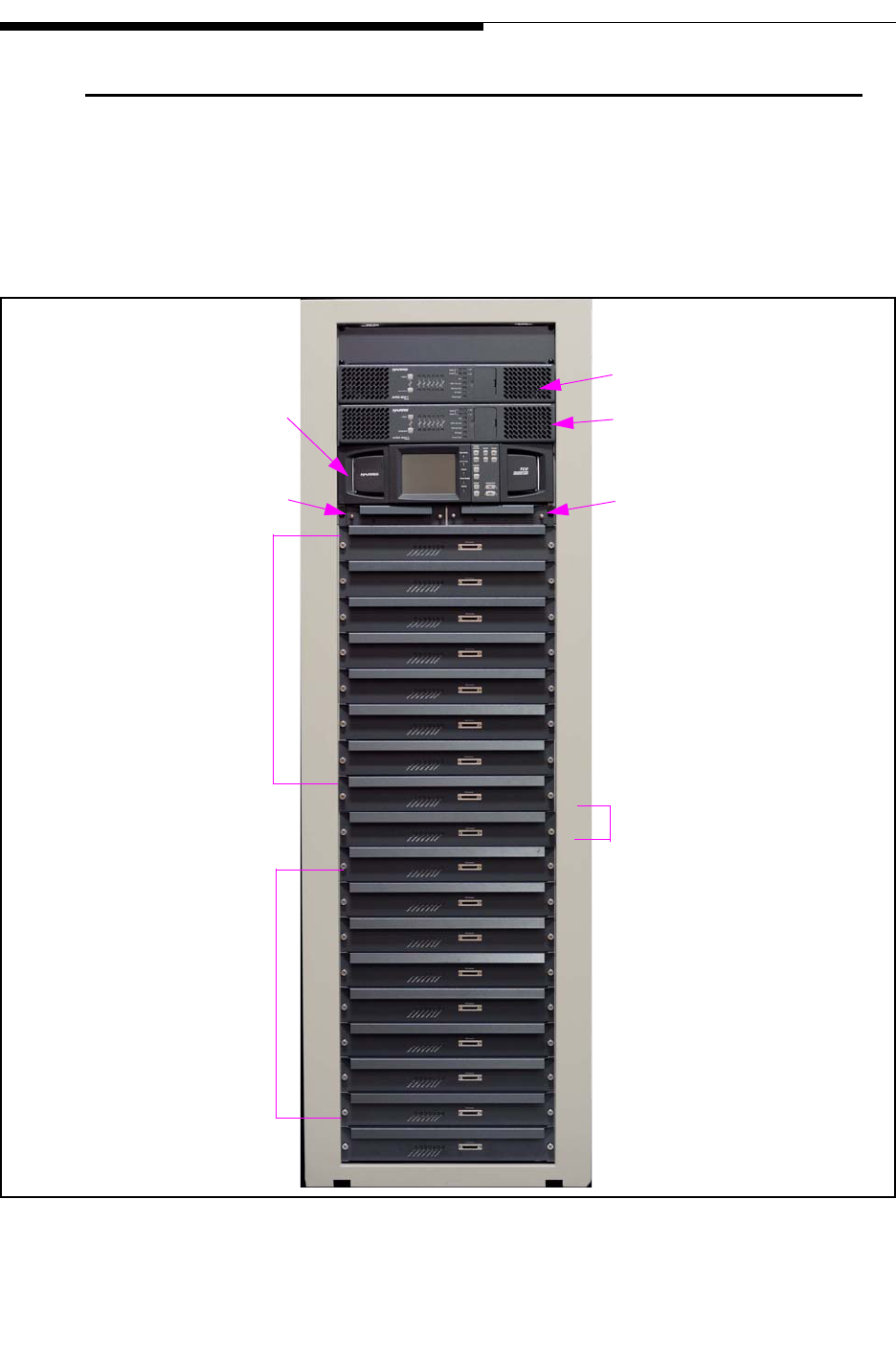
Figure 1-1 ULX-12300AT Front View
Redundant Drivers
Redundant Pre-Driver A
Apex M2X Exciter B
PA Slots 11-18
Apex M2X Exciter A
Redundant Pre-Driver B
PA Slots 1-8
TCU System Controller
IPA A (slot 10)
11
18
A
B
8
1
IPA B (slot 9)
2/19/10 888-2715-001 1-3
WARNING: Disconnect primary power prior to servicing.
Section 1 Introduction
Maxiva ULX ATSC Series
User Manual
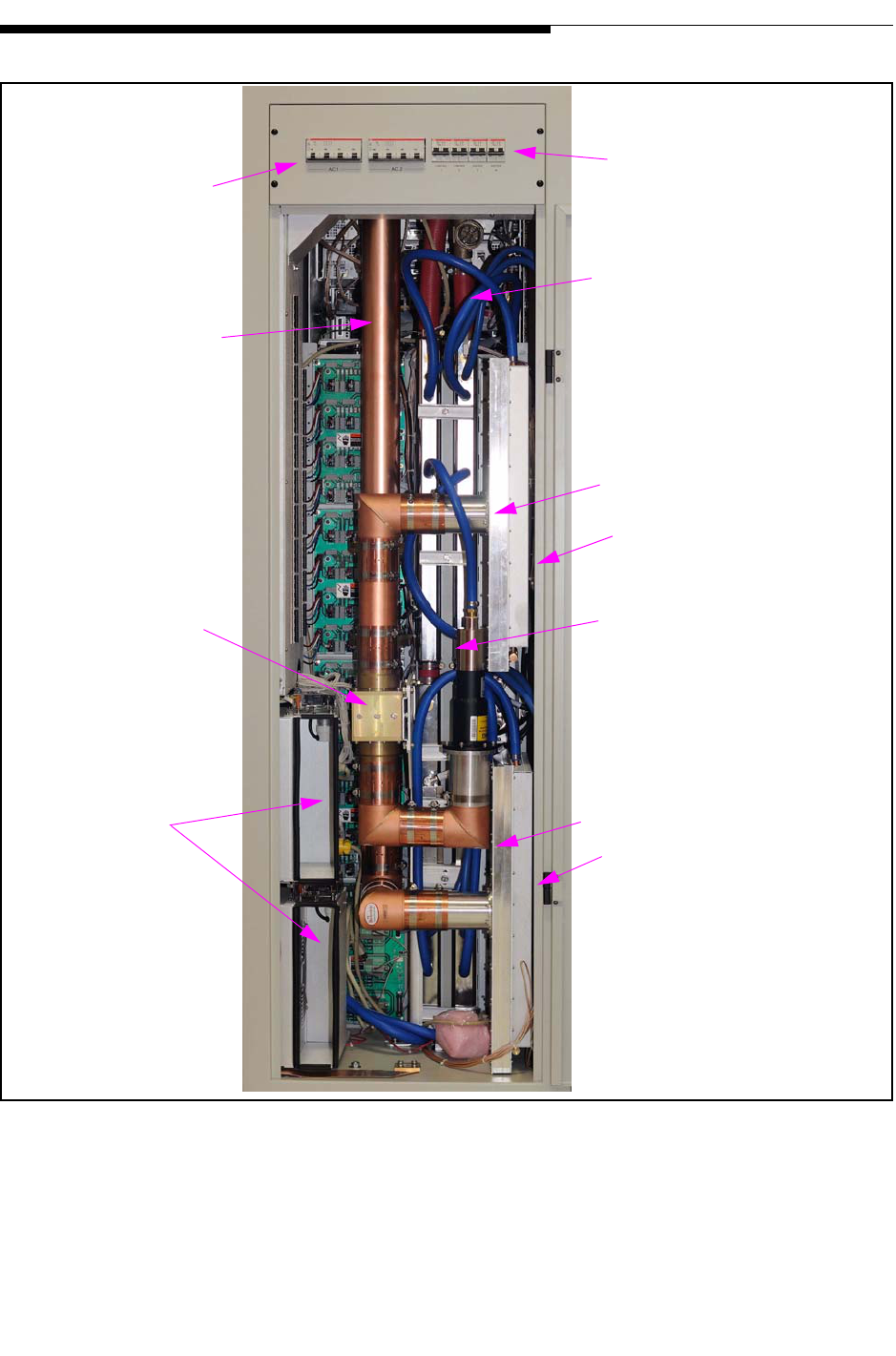
.
Figure 1-2 ULX 12300AT Rear View
Upper 8 Way Combiner
3dB Combiner
Coolant Hoses In/Out
Main Breakers
Final Reject Load
Redundant Cabinet
RF Output Line
Control Breakers
Lower 8 Way Combiner
Blowers (2)
Upper 8 Way Splitter
Lower 8 Way Splitter
1-4 888-2715-001 2/19/10
WARNING: Disconnect primary power prior to servicing.
Section 1 Introduction
Maxiva ULX ATSC Series
User Manual
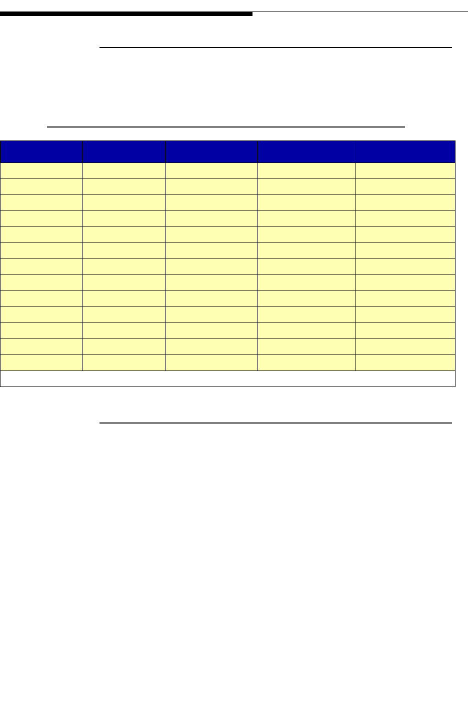
1.2.1 Maxiva ATSC Series Transmitter Models
The Maxiva ULX Series ATSC transmitter is available in 13 liquid cooled power levels.
The models are listed below in Table 1-1
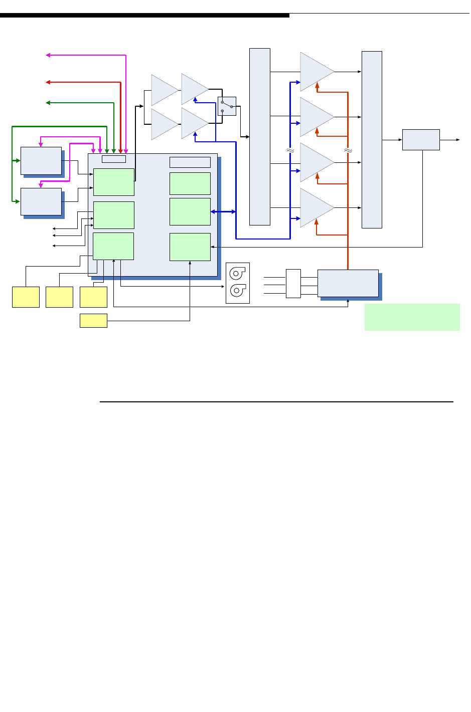
1.2.2 System Block Diagram
Figure 1-3 on page 1-5 contains a system block diagram showing the basic signal flow
and configuration for a Model ULX-12300AT Maxiva ATSC transmitter. The block
diagram shows the 12.3 kW single cabinet, liquid cooled system with 2 pre-amp
modules, 2 driver modules and 16 PA modules. Note that the predriver and driver
modules are redundant.
Table 1-1 Maxiva ATSC Series Transmitter Models
Tx Models Cabinets PA Modules Output Power Primary Cooling
ULX1600AT 1 2 1600W LIQUID
ULX-2400AT 1 3 2400W LIQUID
ULX-3200AT 1 4 3200W LIQUID
ULX-4700AT 1 6 4700W LIQUID
ULX-6300AT 1 8 6300W LIQUID
ULX-7600AT 110 7600W LIQUID
ULX-9200AT 112 9200W LIQUID
ULX-12300AT 116 12.3 kW LIQUID
ULX-13400AT 218(12+6) 13.4 kW LIQUID
ULX-17800AT 224(12+12) 17.8 kW LIQUID
ULX24600AT 232(16+16) 24.6 kW LIQUID
ULX-25800AT 336(12+12+12) 25.8 kW LIQUID
ULX-36900AT 348(16+16+16) 36.9 kW LIQUID
NOTE: All power levels given in average output power before the bandpass filter.
2/19/10 888-2715-001 1-5
WARNING: Disconnect primary power prior to servicing.
Section 1 Introduction
Maxiva ULX ATSC Series
User Manual
Figure 1-3 Maxiva ULX-12300AT ATSC Block Diagram
1.2.3 Transmitter Control System
The Maxiva ATSC transmitter uses a simplified control system that minimizes the
number of microprocessors. Each transmitter sub-system is responsible for its own
monitoring and protection and simply reports back to the TCU (transmitter control unit)
for display on the GUI (Graphical User Interface) or to a remote interface. In multi-
cabinet systems the TCU in cabinet 1 functions as the main controller while the TCU in
each amplifier cabinet acts as a slave controller. The cabinet 1 TCU will contain the
GUI display for the transmitter. Additional PA cabinets do not contain GUI screens.
The system bus originates in MCM (master controller module) inside the cabinet 1 TCU
and goes to the TCU located in each amplifier cabinet. The system bus is used to
transfer telemetry information in between the TCU’s.
The cabinet bus is similar to the system bus but it connects the cabinet TCU (MCM
card) to all of the nodes inside each individual cabinet. If system bus communications
with the master TCU (in cabinet 1) are interrupted the cabinet bus allows each cabinet
to operate independently.
EX 1
EX 2
MOV/AC
SAMPLING
TCU
Ȉ
GUI
RF
SWITCH
PS AND
COOLING
MONITOR
RF
MONITORING
÷DIR
COUPLER
PUMP CONTROL
INTERLOCKS
PARALLEL
REMOTE
TO PUMP MODULE
PA Bus
CABINET
FLOW
METER
INLET /
OUTLET
TEMP
LEAK
DETECTOR
I/O PANEL
Transmitter
Main Cabinet
PA
INTERFACE
AC
Distribution Bus
Driver-PAs
16 PA’s
CAN Bus
Exciter CAN Bus
TO OTHER
CABINETS
N+1 CAN Bus
TO N+1
CONTROLLER
INTERLOCKS
PARALLEL
CONTROL
Front Panel
Buttons
System /CAN Bus
Ethernet
Ethernet
Ethernet
Web
Remote /
Monitoring
L1
L2
L3
FANS
Pre-Drivers

1-6 888-2715-001 2/19/10
WARNING: Disconnect primary power prior to servicing.
Section 1 Introduction
Maxiva ULX ATSC Series
User Manual
The heart of the control system is the TCU which is responsible for control, monitoring
and protection. The TCU contains the MCM (master controller module) which controls
all critical transmitter functions and the PCM (processor control module) which
provides enhanced monitoring and control, exciter and cabinet data collection, fault
logs and web remote connectivity. In addition to the MCM and PCM the Maxiva ATSC
main TCU contains six modular cards for the following sub-systems:
•PA Interface -Provides interface between TCU, IPA (driver) and PA backplane
boards. The interface features 40 digital outputs/inputs and 24 ATSC outputs and
inputs. A fully populated cabinet will require two PA interface cards, one card per
eight PA modules. The PA interface card sends the ON/OFF commands to the PA
modules and receives fault information and status from them.
•RF Detector/Pump Control/ Interlocks - Consists of a main board and a daughter
card. It features 7 RMS detectors with adjustable trip points (via EPOTS). It has
pump control and interlocks on one D25 pin connector.
•Customer I/O - Provides parallel remote control, status and meter outputs. Connector
A has all inputs and Connector B has all outputs.
•Exciter Switch - Contains PWB relay, 2 RMS detectors with adjustable trips (via
EPOTs) for power monitoring and a control/status interface for Exciters A and B.
•PS Monitor - Monitors AC lines for phase imbalance and high or low voltage, cool-
ant inlet/outlet temperature, coolant flow, leaks, combiner temperature and cabinet
fans.
TCU’s also contain the following components:
•Base-Plane - provides a common bus for custom plug-in cards
•Power Supply Modules - two redundant internal power supply modules.
•Standard Master Control Module (MCM) - FPGA based controller used for all criti-
cal transmitter control functions.
•LED’s - standard front LED mimic display panel.
•Processor Control Module (PCM) - Coldfire based micro module running embedded
Linux OS. It provides a touch screen for enhanced monitoring and control, exciter
and multi-cabinet data collection, fault logs and web remote connectivity.
•Graphical User Interface (GUI) front panel - 5.25" color 1/4 VGA touch screen that
is present only in the main TCU (cabinet 1 in multi cabinet systems).
In multi-cabinet systems, there is a TCU in every cabinet. Each TCU will always
contain an MCM but PA cabinet TCU’s don’t require all TCU cards. The TCU in the
first PA cabinet will assume the role of master controller for the system. The TCU’s in
the remaining PA cabinets will be slaves.
2/19/10 888-2715-001 1-7
WARNING: Disconnect primary power prior to servicing.
Section 1 Introduction
Maxiva ULX ATSC Series
User Manual
1.2.4 Transmitter RF Power Control
The PA modules operate in open loop mode (no gain or level adjustment). The
transmitter RF power control is done via the Phase and Gain Board located in the
predriver modules. The predrivers are the only components in the drive chain (besides
the exciter) capable of adjusting their RF power based on commands from the TCU.
Each cabinet can also be placed in the "Manual Power Control Mode". In this mode the
automatic level control is disabled.
1.2.4.1 Graphical User Interface
The TCU front panel (in the control PA cabinet on multi-cabinet transmitters) contains
the graphical user interface which is a 5.25" 1/4 VGA, LCD touchscreen display. The
touchscreen display uses software buttons to monitor and control the transmitter.
Hardware buttons for the primary transmitter functions such as ON, OFF, RAISE and
LOWER are provided on the overlay panel next to the display.
TCU’s in additional PA cabinets will not be equipped with GUI screens.
Figure 1-4 TCU Front Control Panel
1.2.5 Control System Communications
The control system uses a serial communications system called a CAN bus. CAN stands
for Controller Area Network. The CAN bus is a closed loop serial network controlled
by the main TCU. The CAN bus connects the main TCU with TCU’s in other cabinets.
Each TCU board connected to the CAN bus is considered a node and therefore has a
specific address. This allows the master TCU to use the system bus to gather
information from all parts of the transmitter and display it on the GUI. One big

1-8 888-2715-001 2/19/10
WARNING: Disconnect primary power prior to servicing.
Section 1 Introduction
Maxiva ULX ATSC Series
User Manual
advantage of the CAN bus is that it requires only 2 wires of the system control bus
ribbon cable, eliminating a large amount of discrete wiring which would otherwise be
required.
The system bus ties TCU’s in each cabinet together. The cabinet bus is for the most part
a duplicate of the system bus but intended to connect nodes within each individual
cabinet. The cabinet bus originates in the MCM module within each TCU. The cabinet
bus is designed to keep the PA cabinets operating even if the communications with the
master cabinet TCU is lost.
1.2.5.1 Software Updates
The use of the CAN bus for communication between the various Micro Modules in the
transmitter also allows updating of the software used in each transmitter sub-system via
a serial port connection to an external computer.
NOTE:
Software does not need to be loaded into the transmitter unless new components
are installed or an update is sent from Harris. The transmitter, as shipped from the
factory, is preloaded and ready to run.
1.2.5.2 Remote Control
The Maxiva Series ATSC transmitter has the basic discrete wired parallel remote
control with the standard connections for control, status and analog monitoring located
on the customer I/O card inside the main TCU(cabinet 1).
Maxiva transmitters include Web enabled remote GUI interface that provides
comprehensive remote control and monitoring of data points within the transmitter. It
includes an SNMP (Simple Network Management Protocol) manager which allows
integration with most Control Systems via the Internet or LAN.
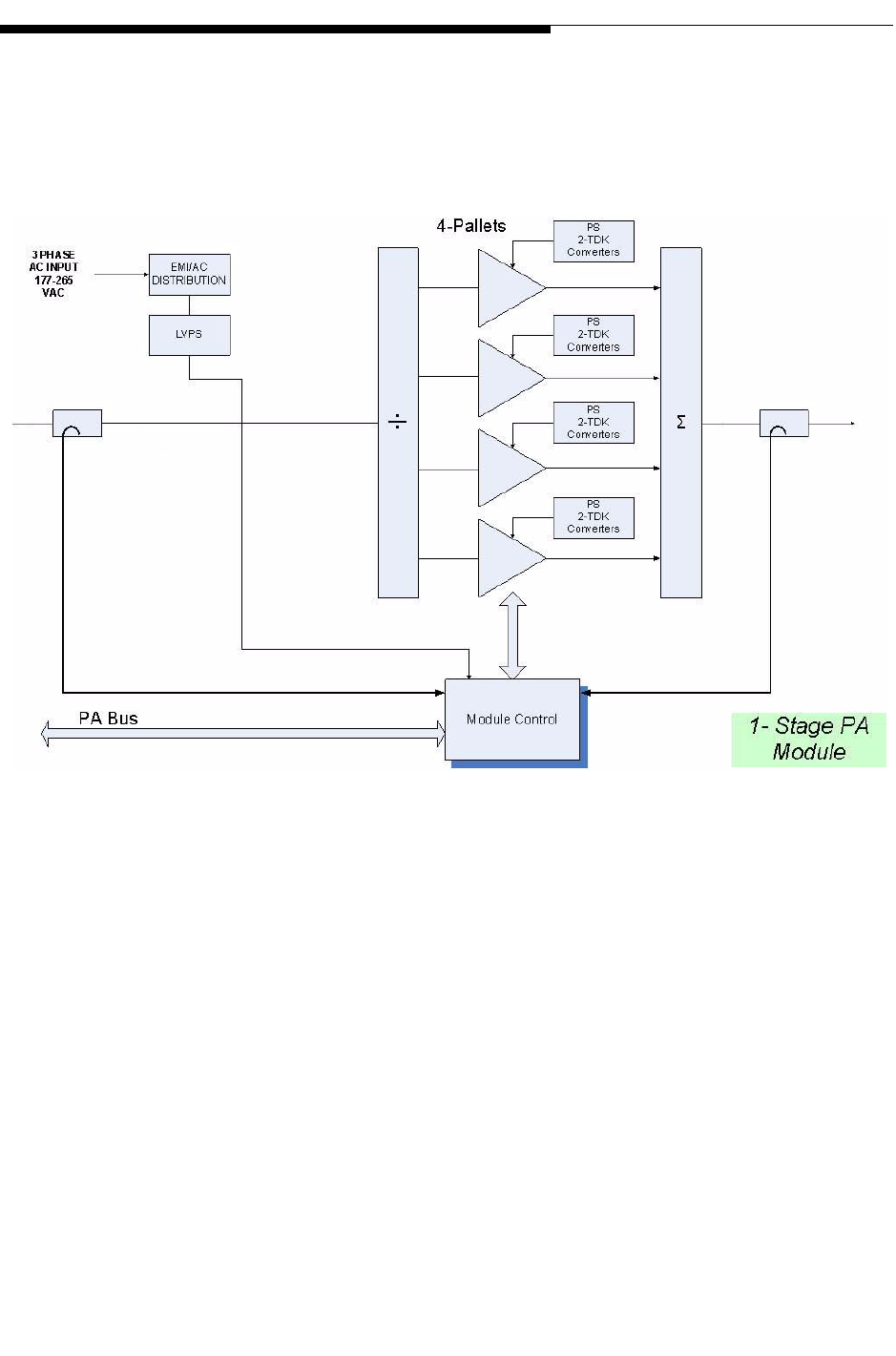
1.2.6 PA Module
The Maxiva ULX Series PA Module utilizes LDMOS (laterally diffused metal oxide
semi-conductor) amplifiers to produce up to 800 W average power output. Each module
weighs approximately 22kg and can be removed while the transmitter is running. A
single cabinet Maxiva Series transmitter can have 2, 3, 4, 6, 8, 10, 12, or 16 PA modules
to achieve the various power levels shown in Table 1-1 page1-4. A simplified block
diagram of the PA module is shown in Figure 1-5 on page 1-9.
2/19/10 888-2715-001 1-9
WARNING: Disconnect primary power prior to servicing.
Section 1 Introduction
Maxiva ULX ATSC Series
User Manual
The amplifier and driver modules are interchangeable and do not contain
microcontrollers but instead use a CPLD based monitor board in each PA to report
faults to the TCU and to take appropriate self-protective action if needed.
Figure 1-5 PA Module Simplified Block Diagram
1-10 888-2715-001 2/19/10
WARNING: Disconnect primary power prior to servicing.
Section 1 Introduction
Maxiva ULX ATSC Series
User Manual
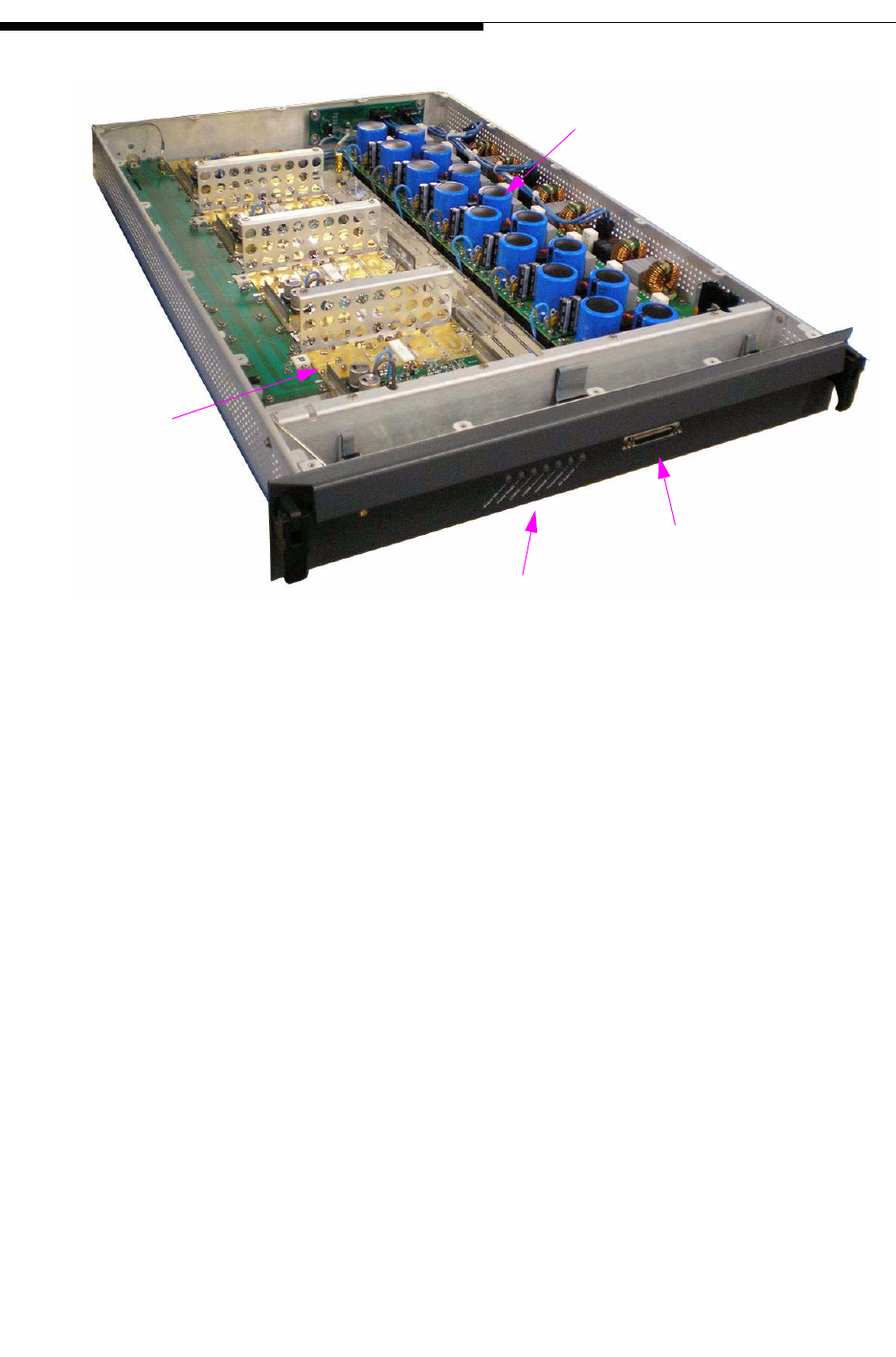
Figure 1-6 Maxiva PA Module (cover removed)
The diagnostic port shown in Figure 1-6 allows the operator to connect directly to the
PA module with a handheld device and obtain PS voltages, fault status, FWD and REF
RF power levels and internal temperatures. The diagnostic port can also be used to
reprogram the CPLD as required.
8 AC-DC Converter Modules
4 RF Pallets
Status LED’s
Diagnostic Port

2/19/10 888-2715-001 1-11
WARNING: Disconnect primary power prior to servicing.
Section 1 Introduction
Maxiva ULX ATSC Series
User Manual
Figure 1-7 Maxiva ULX PA Module (top view, cover removed)
Each PA module consists of the following components:
a. Monitor Board - Responsible for all monitoring and protection of the module.
Reports to the transmitter TCU via the parallel control lines.
b. Connector I/O Board -I/O Connector Board provides interface connections
between PA Module and transmitter back plane. The board includes a single
hybrid connector on one side and five (5) connectors on the other side. The large
hybrid connector interfaces with mating connector on the back plane board. It
contains seven (7) AC contacts, twenty four (24) small signal contacts, and a sin-
gle RF coaxial connector.
c. AC Distribution Board - The AC distribution board provides three phase AC to
the eight power supply boards. It also provides AC line filtering, step-start func-
tion and transient protection for the module.
d. Power Supply Boards - The eight (8) AC/DC power supplies provide 44VDC to
50VDC power to each pair of FET’s on the four (4) PA pallets. Voltage varies
with modulation type and channel.
Coolant
In/Out
RF Out
Coolant
a
ca
g
h
e
da
b
f
i

1-12 888-2715-001 2/19/10
WARNING: Disconnect primary power prior to servicing.
Section 1 Introduction
Maxiva ULX ATSC Series
User Manual
e. Splitter Board - The splitter board equally divides the RF signal between four (4)
power amplifier pallets. The splitter is broadband (covers TV band IV/V). The
splitter board also delivers a detected RF sample to the monitor board to indicate
input power level and provide protection from excessive input drive power.
f. Signal Distribution Board - Signal Distribution Board serves to route analog and
digital control and monitoring data between four (4) PA module board subassem-
blies, monitor board, PA pallets, connector I/O board, and 4-way splitter board.
g. LDMOS Amplifier Pallets - There are four (4) single stage amplifier pallets
operating in parallel in the PA module. When combined, they provide up to 800
watts of average power at the output of the module.
h. Combiner Board - The board combines the RF outputs of the four (4) amplifier
pallets, and delivers the combined signal to the output port. The combiner is
broadband (covers the entire TV Band IV/V) and requires no tuning. The com-
bining of the signals is accomplished using hybrid combiners in series. The first
stage is a 2-way 3dB hybrid, the second stage a 2-way 4.77dB hybrid, and the 3rd
stage is a 2-way 6dB hybrid. The use of reject loads in conjunction with the
hybrids allows continuous operation of the PA Module in the event of a PA Pallet
failure. The combiner contains Forward and Reflected signal directional couplers
at its output. Detector circuits deliver the forward and reflected output samples to
the Monitor Board, which indicates the forward power level in dBm and uses the
reflected signal for VSWR monitoring and VSWR fault protection for the mod-
ule. Another directional coupler provides an attenuated sample of output RF sig-
nal to an optional coaxial port at the front of the PA module.
Each Maxiva ATSC PA Module is a self-contained 800W transmitter including the
power supply with its own internal control, monitoring and protection. The modules
only receive basic On/Off, Mute, & Restart commands from the transmitter control
system. This means that each module will protect itself without relying on the TCU.
1.2.6.1 Module Control
The primary method for control and monitoring of the PA Modules is via the individual
50 conductor ribbon cable bus to one of the two TCU assembly PA Interface boards.
These busses are called Drive A (for preamp A and IPA A), Drive B (for preamp B and
IPA B), and BP 1 through BP 4 (for PA backplanes A5, A6, A8, and A9 respectively).
Each module contains a CPLD based monitor board that is responsible for reporting
faults back to the TCU and for taking action when the ON/STBY command is issued
from the TCU. The cabinet bus connects to each PA and IPA Module backplane, but it
is only used for the PA_voltage_select line, which sets the DC output voltage of each of
the eight AC to DC converters in the IPA and PA modules. The output can be switched
between 44, 46, 48, or 50 VDC, depending on the operating frequency.

2/19/10 888-2715-001 1-13
WARNING: Disconnect primary power prior to servicing.
Section 1 Introduction
Maxiva ULX ATSC Series
User Manual
1.2.7 Transmitter Power Supplies
Three phase AC mains must be supplied to the cabinets via circuit breaker CB23 and
CB24 on the AC mains input assembly (A15). The transmitter can accept 208-240VAC
(Delta or WYE) or 380-415VAC (WYE) by changing jumpers in three areas:
• Terminal boards TB1 and TB2
• Parallel MOV boards (A15A1 & A15A2)
•IPA (driver) and PA backplane boards
If properly jumpered there will be three phase 208-240V AC inputs supplied to each
driver and PA module.
! CAUTION:
THREE PHASE 440-480VAC AC MAINS CAN ALSO BE USED BUT ONLY WITH
AN EXTERNAL TRANSFORMER WHICH CAN BE ORDERED SEPARATELY
FROM HARRIS.
The 208 to 240VAC is supplied to each PA module’s connector I/O board and then to
the modules AC distribution board. There it is applied to eight AC/DC converters (two
per pallet). Depending on the operating frequency, the AC/DC converter output can be
switched between 44, 46, 48, or 50 VDC, which is supplied to each of the eight FET’s
in the module. There are two FET’s on each of the four pallets in each module.
The control system in the transmitter is powered by two low voltage power supply
(LVPS) modules in the TCU.
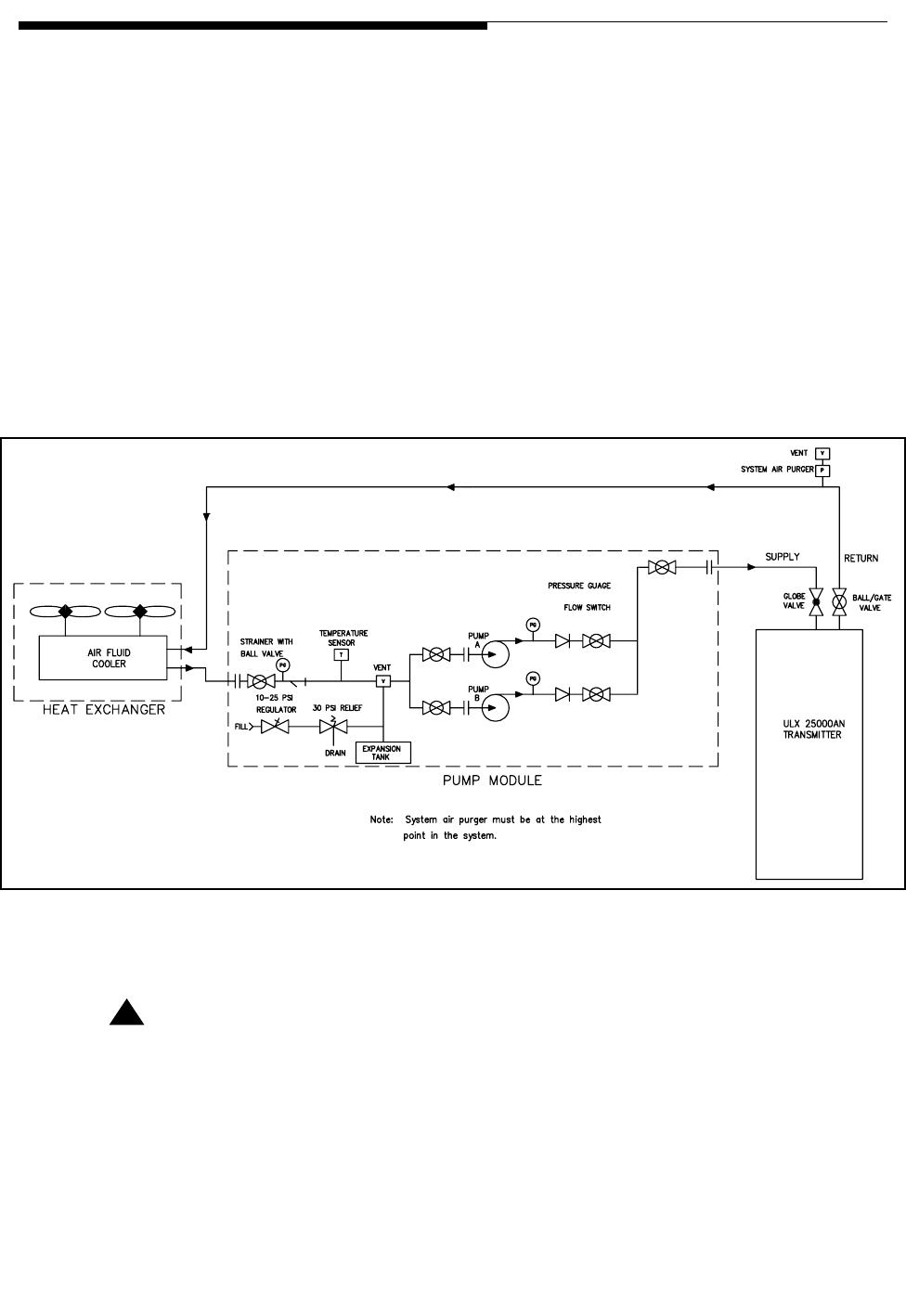
1.2.8 Cooling System
The Maxiva ATSC transmitter uses a 50/50 glycol/water cooling system to remove the
majority of the heat away from the transmitter but also has cabinet flushing fans to
remove residual cabinet heat. A simplified block diagram of the liquid cooling system is
shown in Figure 1-8 on page 1-14. A simplified diagram of the liquid cooling system
inside the transmitter cabinet is shown in Figure 1-12 on page 1-21. The cooling system
basically consists of:
a. Cooling System Control Panel/Pump Module & /Heat Exchanger Unit
b. Air purger located at the highest point in the cooling system.
c. Coolant strainer.
1-14 888-2715-001 2/19/10
WARNING: Disconnect primary power prior to servicing.
Section 1 Introduction
Maxiva ULX ATSC Series
User Manual
d. Supply and return line hose and fittings.
e. PCI (pump control interface) located in the TCU
f. Transmitter PA Module, Splitter and Combiner Cold Plates
The liquid cooling system is an efficient closed loop, pressurized system. Prior to
operation the cooling system must be properly prepared for operation and bled to
remove trapped air. Instructions for cooling system preparation can be found in the
ULX technical manual.
The heat exchanger & pump module units operates on either 208-240 VAC, 50/60 Hz or
380-415 VAC 50/60 Hz. The operating voltages and frequencies should be provided at
time of order. The number of heat exchanger fans will vary with model number.
Figure 1-8 Simplified Liquid Cooling System Block Diagram
! CAUTION:
SOME MAXIVA ULX SERIES TRANSMITTERS WILL NOT SUPPORT A WATER
COOLED TEST LOAD. AN AIR COOLED LOAD SHOULD BE USED WITH ULX SERIES
TRANSMITTERS.
N

2/19/10 888-2715-001 1-15
WARNING: Disconnect primary power prior to servicing.
Section 1 Introduction
Maxiva ULX ATSC Series
User Manual
1.2.8.1 Cooling System Control Panel
The cooling system control panel controls the operation of the pump module/heat
exchanger, and sends fault and status information to the TCU. The cooling system
control connects to the RF Detector/Pump Control/Interlocks card in the TCU for
monitoring and control.
NOTE:
The control panel and pump module is designed for indoor use only.
The pump control signals are described below:
+12 Vdc - Voltage supplied by Pump Control Unit.
PUMP_INTLK - Output, active high. When high, the transmitter’s RF output is muted
and the pumps are forced to OFF regardless of the LOCAL/
REMOTE setting in the pump cooling control panel. If this interlock
is active, the pumps can’t be turned ON (even locally). This interlock
is driven by the transmitter or PA cabinet leak detector. If a leak is
detected, this interlock goes to high.
PUMP RUN - Output, active high to turn on selected pump.
SWITCH PUMP - Output, pulsed active high to switch between Pump A and Pump B.
PUMP A SELECTED - Input, connect to open drain or relay contacts. Active when
input is LOW.
PUMP B SELECTED - Input, connect to open drain or relay contacts. Active LOW.
LOCAL STATUS - Input, connect to open drain or relay contacts. Remote = HIGH,
Local = LOW
1-16 888-2715-001 2/19/10
WARNING: Disconnect primary power prior to servicing.
Section 1 Introduction
Maxiva ULX ATSC Series
User Manual
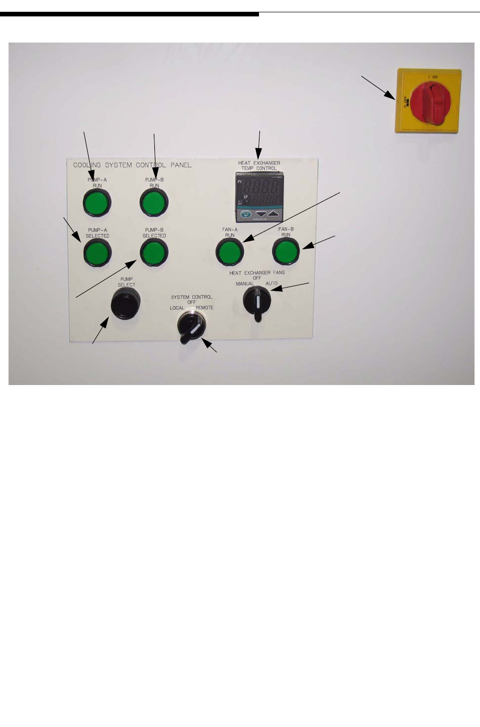
Figure 1-9 Cooling System Control Panel
a. ISOLATOR - ON/OFF
b. HEAT EXCHANGER FANS - Manual, OFF, or Remote
c. PUMP SELECT - A or B pump is selected when pressed
d. TEMP CONTROL - Sets fan cycle temps. Factory settings are fan 1 turns on at
23.9o C. (75oF.) and fan 2 turns on at 26.7oC. (80oF.). These can be adjusted in
the field to more suitable levels. Fan 1 turn on at 32oC and Fan 2 turn on at 37oC
would be typical.
e. SYSTEM CONTROL - LOCAL/REMOTE - Allows local control or remote con-
trol via transmitter.
f. HEAT EXCHANGER TEMP CONTROL - PLC controller used to set fan ON
and OFF temperatures.
The control panel also has the following status indicators:
g. PUMP - A RUN (ON = Green)
AC Isolator ON/OFF
Pump-A
Run LED
Pump-B
Run LED
Fan-A
Run LED
Fan-B
Run LED
Heat Exchanger Fans
MANUAL/OFF/AUTO
System Control
LOCAL/OFF/REMOTE
Temp Controller
Pump Select
Pump-A
Selected
Pump-B
Selected

2/19/10 888-2715-001 1-17
WARNING: Disconnect primary power prior to servicing.
Section 1 Introduction
Maxiva ULX ATSC Series
User Manual
h. PUMP - B RUN (ON = Green)
i. FAN - A RUN (ON = Green)
j. FAN - B RUN (ON = Green)
k. PUMP - A SELECTED (ON = Green)
l. PUMP - B SELECTED (ON = Green)
m. PLC STATUS INDICATOR
When System Control is in Remote mode, see Figure 1-9, the transmitter is
responsible for control of the cooling system, including ON/OFF, manual pump
selection and automatic pump switching in the case of a failure. Placing the control
panel in Local mode allows manual switching of the pumps.
The red selector at the top of the control panel (labeled ON/OFF) is the AC isolation
switch which disconnects AC power from the pump module as well as the control
circuitry in the control panel itself.
In the local mode, with the AC isolation switch set to ON, one of the two pumps will be
energized unless the Pump Interlock is active. To deenergize the pumps, when in the
local mode, set the AC isolation switch to OFF.
1-18 888-2715-001 2/19/10
WARNING: Disconnect primary power prior to servicing.
Section 1 Introduction
Maxiva ULX ATSC Series
User Manual
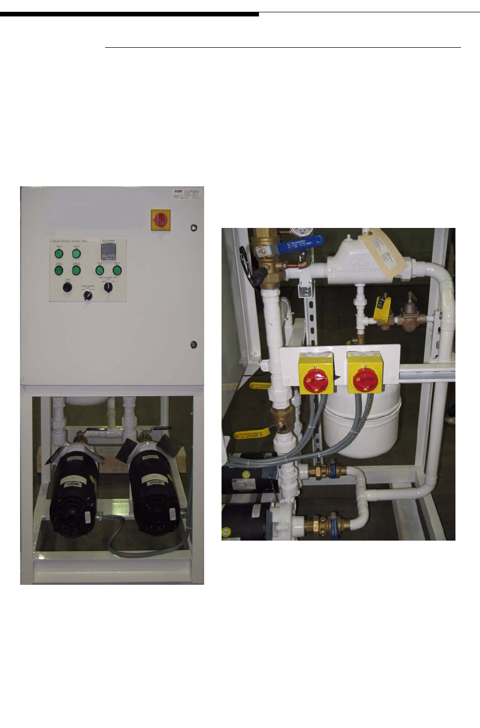
1.2.8.2 Pump Module/Heat Exchanger
The control panel/pump module and heat exchanger are separate units each in a rack.
The control panel and pump module are self-contained in one rack and include a PLC
(programmable logic controller), an expansion tank, air purger, pressure gauges, a
strainer and dual pumps operating in main/standby mode. The control panel/pump
module is designed for indoor operation and should be located near the transmitter if
possible. The heat exchanger assembly is designed for outdoor mounting.
Figure 1-10 Pump Module & Control Panel
Pump Module Front
Pump Module Side
2/19/10 888-2715-001 1-19
WARNING: Disconnect primary power prior to servicing.
Section 1 Introduction
Maxiva ULX ATSC Series
User Manual
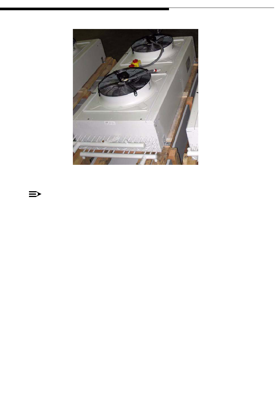
Figure 1-11 Heat Exchanger (before installation)
NOTE:
The heat exchanger shown in Figure 1-11 is a 2 fan unit. It is shown on a shipping
pallet. The two fans that are shown pull air up through the cooling coil/fins (not
visible in the photo) if unit if mounted horizontally (as shown). This unit can be
mounted horizontally or vertically depending on how the legs are attached to the
heat exchanger. Smaller transmitters may use only one fan.
1.2.8.2.1 Heat Exchanger Fan Control
Units with two fans offer redundancy. In multi-cabinet transmitters there will be one
heat exchanger and control panel/pump module per PA cabinet. The fans are controlled
electronically. The fans are enabled whenever the pump module is activated, but the
controller temperature set point, in degrees C, and the proportional band setting, in
degrees C, determines when the fans will actually start. With the controller temperature
set point at 32oC and the proportional band setting at 5oC, the first fan will turn on when
the coolant discharge temperature reaches 32oC, with the second fan turning on at 37oC.
As the coolant discharge temperature drops the fans will be turned off.
1.2.8.2.2 Pump Operation/Control Logic
Pump operation is automatically controlled using a programmable interface device
controller (PID). There are two modes of pump operation, "LOCAL" and "REMOTE".
The PID controller interfaces with the pump control interface (PCI) located in the TCU.
The PLC controller receives and sends signals to the transmitter PCI. With "LOCAL"

1-20 888-2715-001 2/19/10
WARNING: Disconnect primary power prior to servicing.
Section 1 Introduction
Maxiva ULX ATSC Series
User Manual
selected a status signal is sent to the PCI reporting the mode selection. Loss of flow for
more than 5 seconds in an active pump will cause activation of the standby pump. Loss
of flow for more than 15 seconds will cause both pumps to shut down.
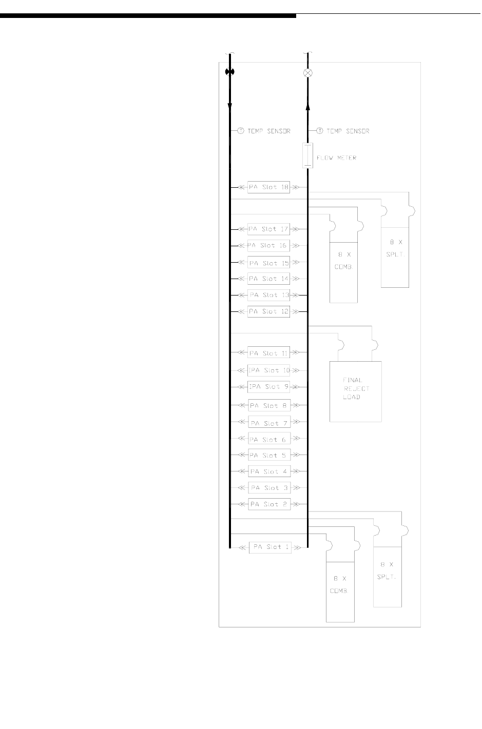
1.2.8.3 PA Module and Combiner Cold Plates
Each PA Module has a liquid cooled cold plate which connects to the cooling system
with quick release connectors. There are also cold plates inside the combiner and the
splitter to which all of the internal combiner reject loads are attached. See Figure 1-12
for cabinet coolant routing and module slot numbering.
NOTE:
The module slot numbering should not be confused with the IPA and PA module
numbering. Module numbering and slot locations will vary depending on model
number. See the outline drawing to identify which PA modules go in which slot
locations dependent on model.
2/19/10 888-2715-001 1-21
WARNING: Disconnect primary power prior to servicing.
Section 1 Introduction
Maxiva ULX ATSC Series
User Manual
Figure 1-12 ULX 12300AT Liquid Cooling System (Internal)
1-22 888-2715-001 2/19/10
WARNING: Disconnect primary power prior to servicing.
Section 1 Introduction
Maxiva ULX ATSC Series
User Manual
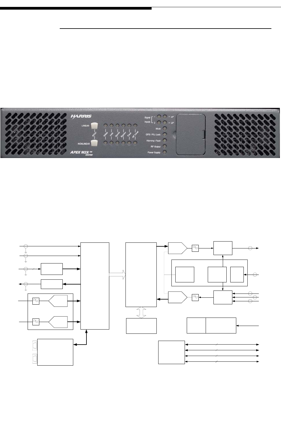
1.2.9 M2X Multimedia Exciter
The M2X exciter is used with the Maxiva ULX Series transmitter. This exciter is
described in a separate instruction book. A second hot standby exciter, and drive chain
switcher is available as an option. The exciter is controlled by the transmitter using an
internal CAN bus or Ethernet connection. Configuration, editing, diagnostics and
monitoring are possible using the front panel on the TCU display, or via Ethernet ports
provided with the exciter.
Figure 1-13 M2X Exciter Front
A single exciter unit drives the Maxiva ULX transmitter. The excellent quality and
stability of ATSC UHF signal output maximizes the TV transmitter efficiency,
improving performance and helping to reduce operating costs.
Figure 1-14 M2X Exciter Block Diagram
Video
Audio
A/D A/D
DVB-ASI/
SMPTE-310
Rcvr & Cable
Equalizer
Modulator
FPGA
DUC/
Precorrector
FPGA
IF
PLL
A/D
RF IN (IPA)
RF IN (PA)
RF IN (HPF)
4
Analog Input
Option Board
D/A
1PPS
10MHz
Up
Converter
Down
Converter
RF
PLL
RF OUT
DSP
uC
10/100 BaseT
8
CAN
2
RS232
2
LVPS AC
Universal
Battery
Backup
Option
GPS Ant
GPS
Option
10/100 BaseT
8
DVB-ASI/
SMPTE-310
Monitor
Cable
Driver
Transmitter
Interface Board
PFRU
Universal Exciter Platform

2/19/10 888-2715-001 1-23
WARNING: Disconnect primary power prior to servicing.
Section 1 Introduction
Maxiva ULX ATSC Series
User Manual
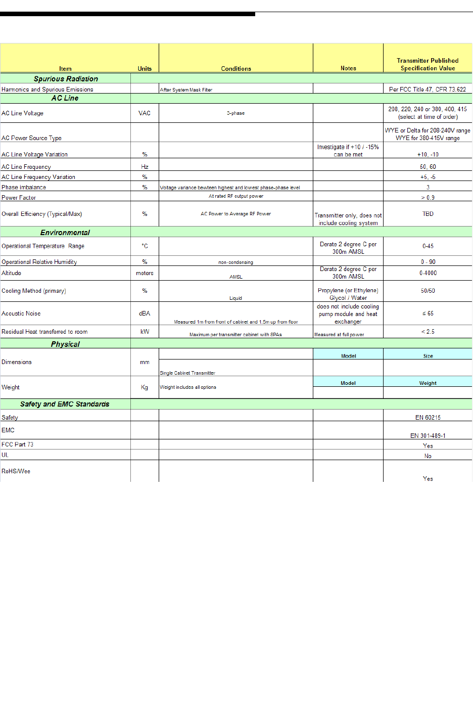
1.3 General Specifications
NOTE:
Specifications subject to change without notice. Unless otherwise noted specifi-
cations apply at the output of the Harris supplied mask filter.
Specifications continue on following pages.
1-24 888-2715-001 2/19/10
WARNING: Disconnect primary power prior to servicing.
Section 1 Introduction
Maxiva ULX ATSC Series
User Manual

2/19/10 888-2715-001 1-25
WARNING: Disconnect primary power prior to servicing.
Section 1 Introduction
Maxiva ULX ATSC Series
User Manual

1-26 888-2715-001 2/19/10
WARNING: Disconnect primary power prior to servicing.
Section 1 Introduction
Maxiva ULX ATSC Series
User Manual

2/19/10 888-2715-001 2-1
WARNING: Disconnect primary power prior to servicing.
Maxiva ULX ATSC Series
User Manual
Section 2
Operation 2
2.1 Introduction
This section gives detailed operational information for the Maxiva ULX Series Solid-
State UHF TV transmitter. Information will pertain mostly to the operation and
navigation of the TCU graphical user interface (GUI) touchscreen display.
NOTE:
Operation of the M2X exciter is covered in a separate manuals which ships with
the transmitter.
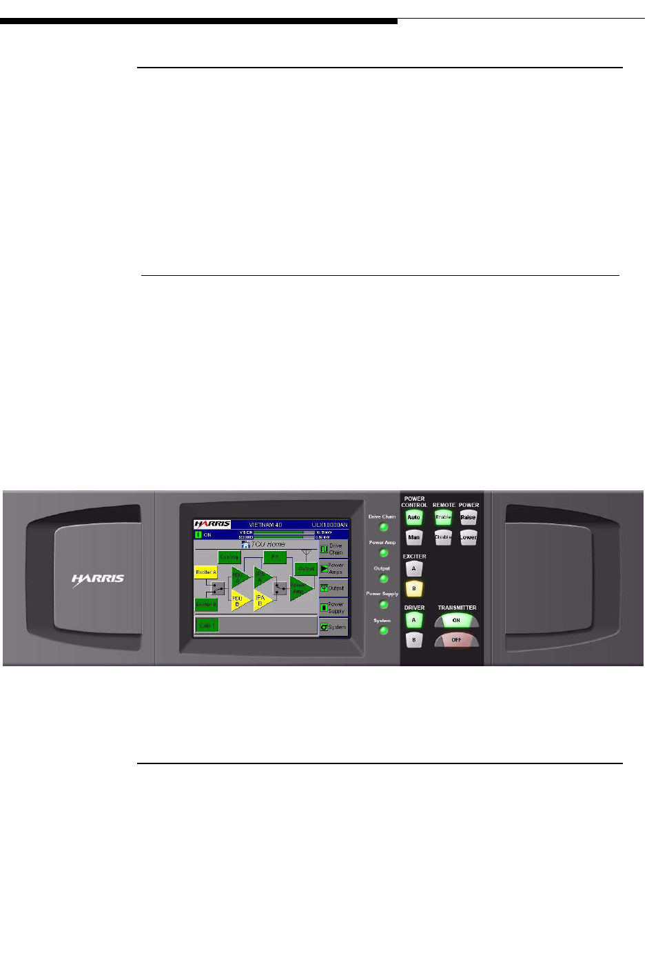
2.2 Transmitter Control Panel
The front panel user interface is a 5.25" 1/4 VGA, LCD touchscreen display. This
touchscreen display uses software buttons to monitor the transmitter. Hardware buttons
for the primary transmitter functions such as ON/OFF, RAISE/LOWER and Remote
Enable/Disable are provided on the overlay panel next to the display as shown in Figure
2-1.
NOTE:
When transmitter is turned off using the OFF button under normal conditions, the
pump module pump will continue to operate for approximately 5 minutes and
then shut off.
2-2 888-2715-001 2/19/10
WARNING: Disconnect primary power prior to servicing.
Section 2 Operation
Maxiva ULX ATSC Series
User Manual
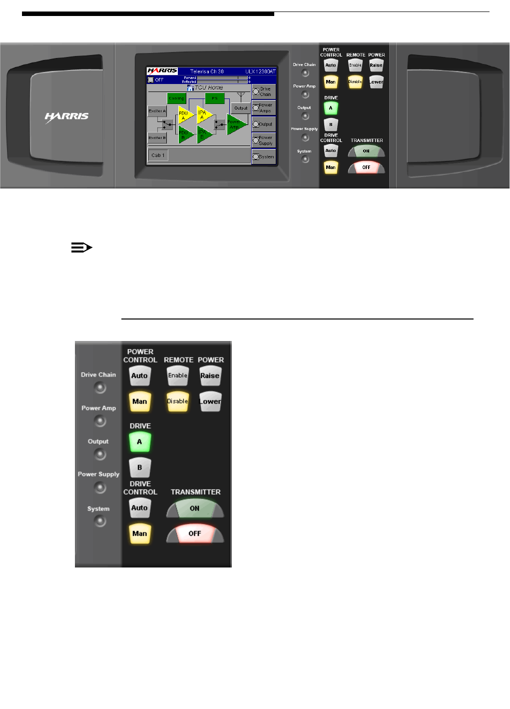
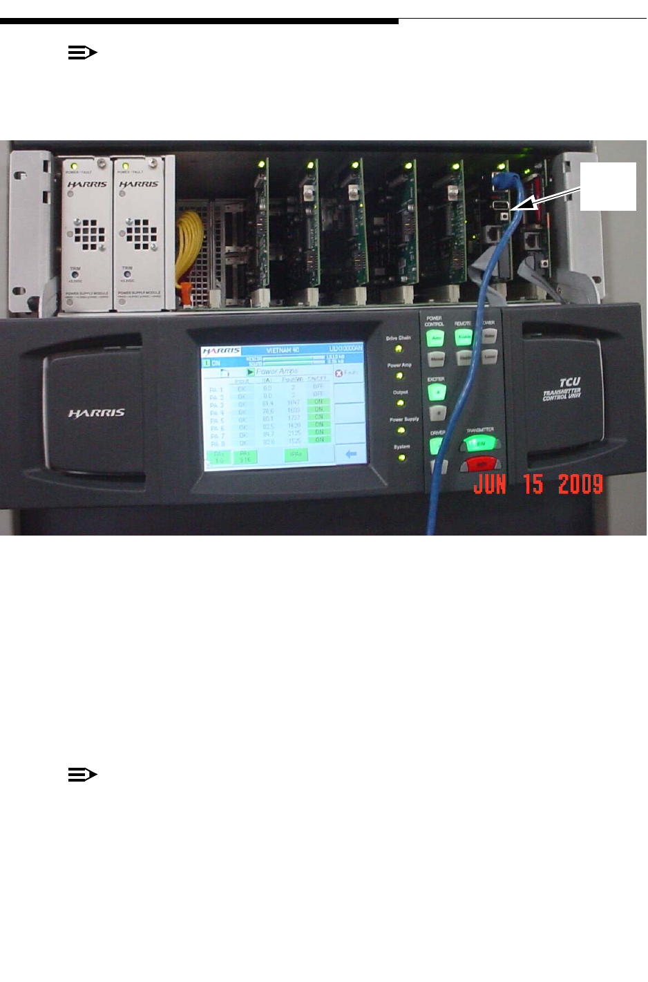
Figure 2-1 Transmitter Control Unit (TCU)
NOTE:
A similar set of GUI screens is available via web browser with an ethernet net-
work connection and the optional eCDi hardware interface.
2.2.1 Hardware Control Buttons
To the right of the touchscreen, there are 6 pairs of
hardware control buttons which are part of the front
panel overlay. Located to the left of the buttons are
Status LED’s which are green under normal, no
fault conditions. The hardware buttons provide
immediate control of 6 main transmitter functions:
a. Power Control - Auto/Manual
b. Remote - Enable/Disable
c. Power - Raise/Lower
d. Exciter - A/B
e. Drive - A/B
f. Transmitter - On/Off
The Status LED’s light amber (yellow) for a warning and red for a fault condition in the
transmitter subsystems. LED’s light green if the sub-system is normal. This provides
quick sub-system status information without having to be familiar with a menu
structure.
SYSTEM
2/19/10 888-2715-001 2-3
WARNING: Disconnect primary power prior to servicing.
Section 2 Operation
Maxiva ULX ATSC Series
User Manual
NOTE:
The system control buttons described above will be referred to as hardware con-
trol buttons in the following manual text.
Figure 2-2 TCU Front Panel Lowered
Should the GUI screen go gray, i.e., the software buttons or symbols are still visible but
have turned shades of gray instead of the usual color scheme, a TCU reset may be
required. To reset the TCU, pull down the GUI panel exposing the circuit cards in the
TCU chassis as shown in Figure 2-2. The second board from the right is the PCM
board. The TCU reset button is located about toward the center of the board and it faces
outward toward the user. Use the tip of a pencil or pen to gently depress the small black
button.
NOTE:
It will take approximately two minutes for the TCU to reset. If the transmitter is
on the air, resetting the TCU will NOT affect transmitter operation.
A TCU reset can also be accomplished by pressing the Local GUI SYSTEM ADMIN
screen REBOOT button.The screen and button are shown in Figure 2-19 on page 2-24.
PCM
Reset

2-4 888-2715-001 2/19/10
WARNING: Disconnect primary power prior to servicing.
Section 2 Operation
Maxiva ULX ATSC Series
User Manual
There is another reset button toward the bottom of the MCM board (farthest board to
the right). This reset button will also reset the TCU but it will take the transmitter off the
air for a short time
Just above the MCM Reset button is a removable memory card containing system
software. This card should be installed in any replacement MCM card that is installed.
2.3 Graphical User Interface (GUI)
The GUI ("Gooey") was designed to provide an intuitive interface into the transmitter
control system. Once you become familiar with content, finding information is a matter
of following the screens to the desired section of the transmitter. Menu Trees of all
available screens are given at the end of this section, see "2.10 GUI Menu Structures"
on page 2-28
For the most part, all navigation through the GUI screens is via the touchscreen and
softkeys (software buttons). The exceptions are the 6 pairs of hardware control buttons
mentioned above. The touchscreen display is also divided into an active display area,
which will change with each screen selected, and the global areas which are present on
all screens.
2.3.1 Global Status and Navigation
The top 2 sections of the touchscreen display (dark blue background) are considered
global because they show up on all screens. The top line indicates the transmitter name
and model number.
2/19/10 888-2715-001 2-5
WARNING: Disconnect primary power prior to servicing.
Section 2 Operation
Maxiva ULX ATSC Series
User Manual
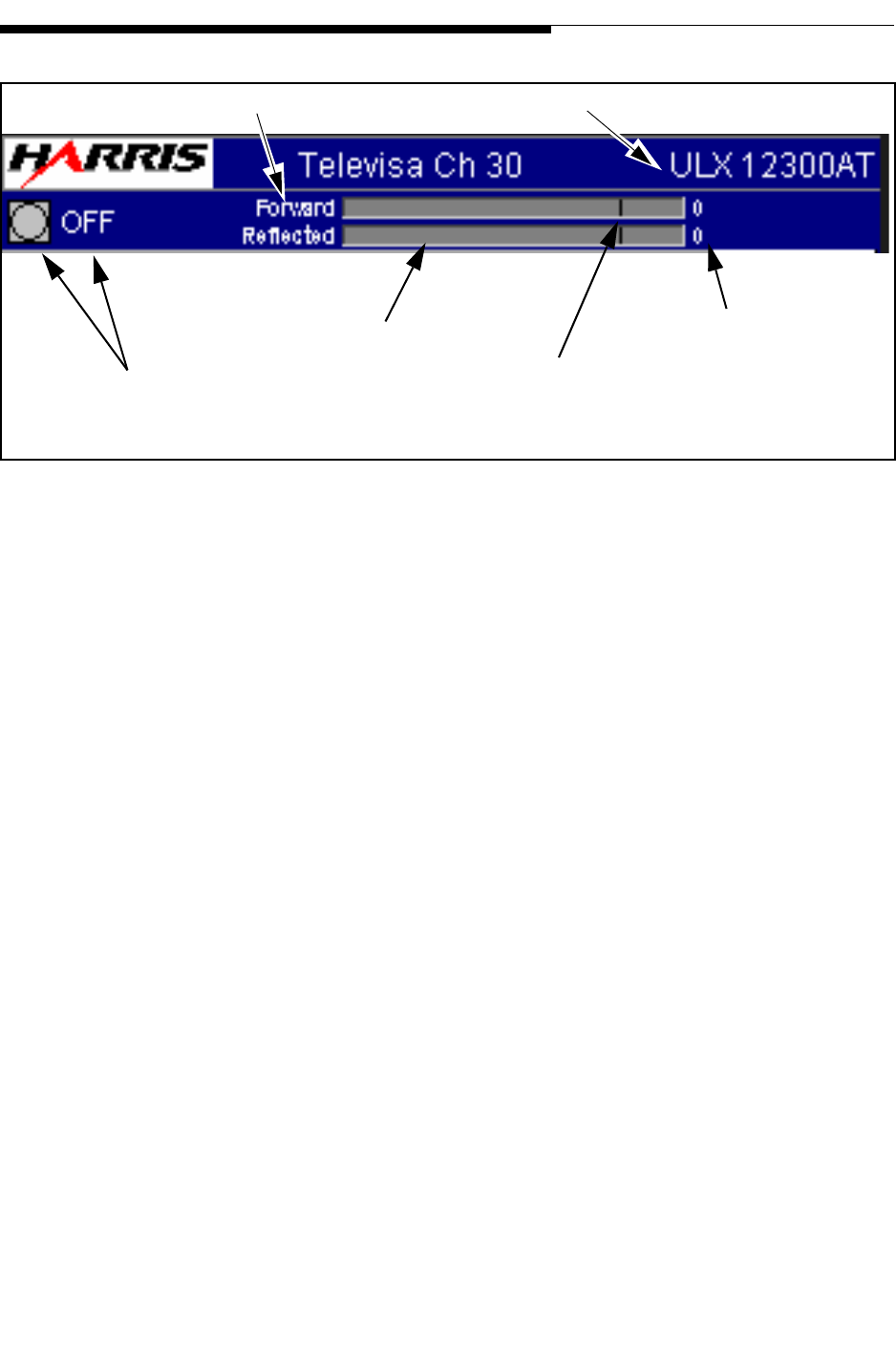
Figure 2-3 Global Display Header
The second line of the display has operational and status information including:
a. ON, Standby, Fault OFF, ON/FB (transmitter foldback), PS MUTE, and RF
MUTE status indication.
• ON: Normal operating mode
• Standby: Transmitter turned off manually or remotely
• Fault OFF: Transmitter forced off due to fault condition
• ON/FB: Transmitter power folded back. Conditions causing the foldback
may by temporary and could possibly be cleared by pressing the ON button.
If, after pressing the ON button to reset the foldback, the ON/FB indication
resumes the malfunction will need to be determined and the transmitter
repaired (see Section 6 for fault log listings).
• PS MUTE: A temporary fault condition caused by a power supply related
fault. If underlying fault clears, the mute condition will be lifted and the
transmitter returned to normal operating mode. If the mute continues, the
underlying fault will need to be determined and the transmitter repaired (see
Section 6 for fault log listings).
• RF MUTE: A temporary fault condition caused by an RF related fault. If
underlying fault clears, the mute condition will be lifted and the transmitter
returned to normal operating mode. If the mute continues, the underlying
fault will need to be determined and the transmitter repaired (see Section 6
for fault log listings).
System Forward Power Bargraph
Transmitter Model Number
Fault & Operational
Status
Forward and Reflected
Power Outputs
Reflected Power Bargraph
100% Mark - Based on
Nominal Power Output setting
in System Setup screen

2-6 888-2715-001 2/19/10
WARNING: Disconnect primary power prior to servicing.
Section 2 Operation
Maxiva ULX ATSC Series
User Manual
b. Transmitter Forward power output reading in numerical format (for multiple
cabinet transmitters this would be a system power reading and not for a single
cabinet). It is important to note that this is the power output after the filter.
c. Transmitter Forward power output reading in a Bargraph format. The 100% mark
is based on the nominal power level or TPO (Transmitter Power Output) entered
into the configuration screen. The bargraph will also turn yellow if the power
level is more than 10% higher or lower than the nominal 100% level.
NOTE:
Indications on the global display header in Figure 2-3 should be all green under
normal (no fault) operating conditions. A yellow or red symbol or status indica-
tion on the global display header should be investigated by the station engineer.
2/19/10 888-2715-001 2-7
WARNING: Disconnect primary power prior to servicing.
Section 2 Operation
Maxiva ULX ATSC Series
User Manual
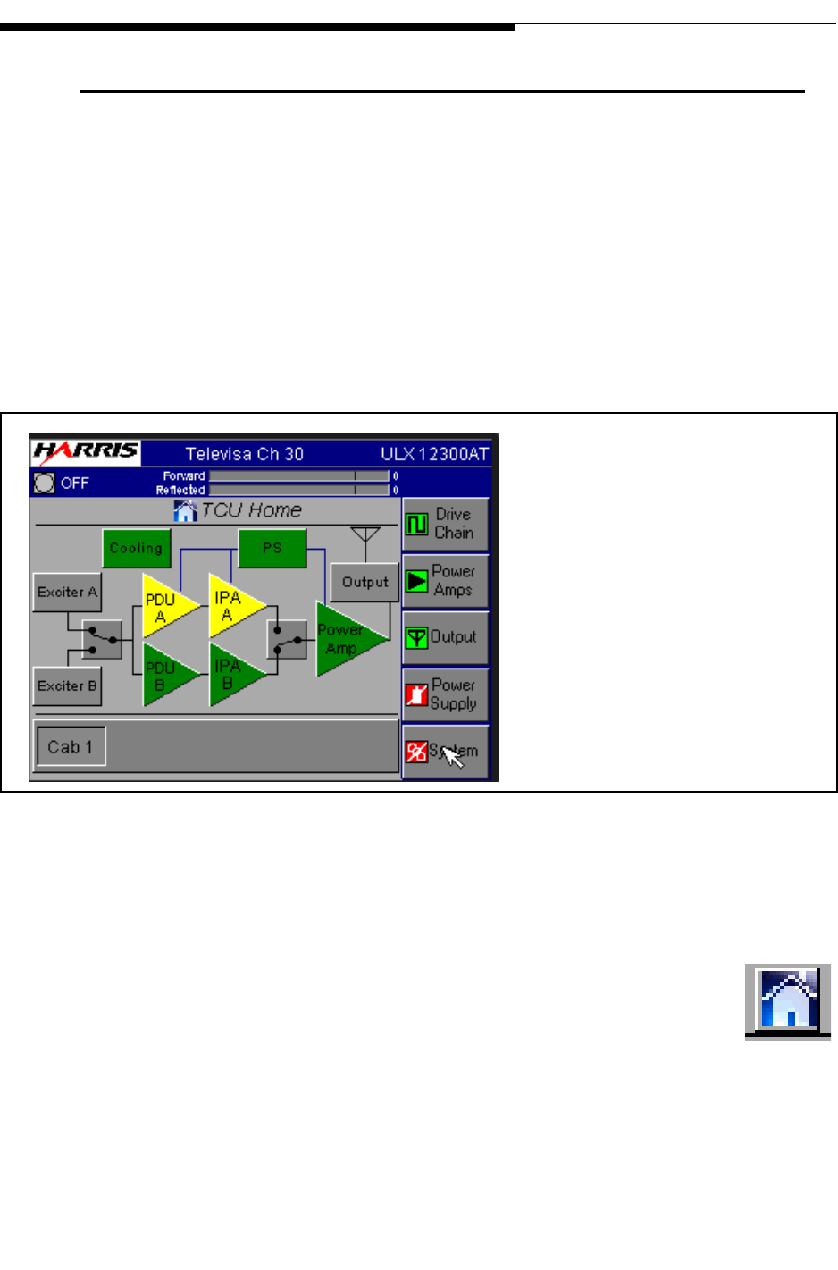
2.4 GUI Home Screen
The HOME screen shown in Figure 3-3 is the primary operator screen and the default
screen after boot up. The HOME screen contains the most important general operator
information such as:
a. Cooling status
b. Power supply status
c. Drive chain selection (pre-driver and IPA status)
d. Amplifier status
Figure 2-4 ULX-12300AT Home Screen
It also has the global status and operation information at the top of the screen which
shows the transmitter status, power output and any faults present.
The HOME button (shown to the right) is a software button located in the
upper left quadrant of all 5 main menu screens for quick navigation to the
HOME screen. If a submenu screen is displayed on the GUI (see Figure 2-
4), the lower right-hand button will typically be the BACK (arrow) button;
use this back arrow button to go back up a level.
To Figure 2-5 on page 2-9
To Figure 2-8 on page 2-13
To Figure 2-10 on page 2-15
To Figure 2-12 on page 2-17
To Figure 2-14 on page 2-19

2-8 888-2715-001 2/19/10
WARNING: Disconnect primary power prior to servicing.
Section 2 Operation
Maxiva ULX ATSC Series
User Manual
The quickest way to access the HOME screen is to press either the HOME button on a
main menu screen or the BACK button arrow on a submenu screen followed by a
HOME button press on the main menu screen.
There are five touchscreen navigation buttons on the right side of the GUI Home
display. These buttons vary from screen to screen. The software menu buttons can also
act as status indicators and turn red if a fault condition is detected.
There is a navigation button (shown to the right) to allow access to
information specific to the PA cabinet. Pressing this button will take you
to the Power Amp screen shown in Figure 2-8 on page 2-13.
This button is also a status indicator for the PA cabinet as it will change
from green to red, if a problem is detected in that cabinet.
NOTE:
To simplify the discussion of GUI navigation, the following sections describe the
screens under the 5 main menu buttons located on the right side of the GUI Home
page.
Similarly, pressing the exciter, PDU or IPA icons will take you to the main drive chain
menu.
2/19/10 888-2715-001 2-9
WARNING: Disconnect primary power prior to servicing.
Section 2 Operation
Maxiva ULX ATSC Series
User Manual
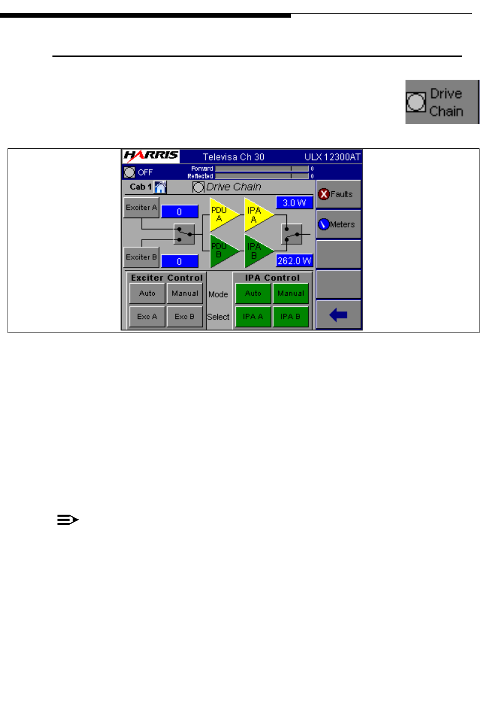
2.5 Drive Chain Main Menu
If you press the Drive Chain button on the HOME screen, it will take
you to the screen shown in Figure 2-5. The Drive Chain Menu structure
is shown in Figure 2-24 on page 2-29.
Figure 2-5 Drive Chain Screen
The Drive Chain screen is basically an exciter, pre-driver and IPA control and
monitoring screen. It has a power reading for each exciter and IPA output and allows
the operator to select exciters and pre-driver/IPA’s. It also allows selection of AUTO or
MANUAL switching mode for the drive chain when the optional dual exciter system is
installed. Specifically it includes:
a. The operational and on-air status of 1 or 2 exciters (the second exciter is optional)
pre-drivers and IPA’s.
NOTE:
The standard M2X exciter comes with a main and aux input.
b. The status of Exciters and Drivers A and B. The screen also allows exciter and
driver selection.
c. A Dual Exciter Control box (located at the bottom of the screen on the left). This
section will be grayed out for single exciter systems. For dual exciter systems this
box has two exciter buttons and Auto/Manual buttons:
To Figure 2-6
To Figure 2-7
To Figure 2-4

2-10 888-2715-001 2/19/10
WARNING: Disconnect primary power prior to servicing.
Section 2 Operation
Maxiva ULX ATSC Series
User Manual
1. Auto/Manual - Auto should be the standard position for normal operation.
Placing it in Manual mode prevents an autoswitch to the alternate drive
chain. In AUTO mode, if the on-air exciter drops below 50% of nominal
power, or if the on-line exciter experiences a fault, the controller will auto-
matically switch to the backup drive chain (if available). Manual mode
could be used if an exciter or driver has been removed for service or for
any application where an automatic switch to the alternate drive chain is
not desired.
2. Exciter A/B - These buttons select operational exciter. To use these
buttons, place the Auto/Manual button to Manual, then press the A or B
button to select the on-air drive chain.
d. Pre-Driver/IPA Control box (located at the bottom of the screen on the right).
This dual driver has 2 switches:
1. Auto/Manual - This toggle button should always be in the Auto position for
normal operation. Placing it in Manual mode prevents an autoswitch to the
alternate IPA (Preamp/Driver). In AUTO mode, if the on-air predriver/IPA-
drops below 50% of nominal power, the controller will automatically
switch to the backup pre-driver/IPA. Manual mode could be used if a
exciter or driver has been removed for service or for any application where
an automatic switch to the alternate IPA(Preamp/Driver) chain is not
desired.
2. Pre-driver/IPA A/B - These are the manual selection buttons. To use these
buttons, place the Auto/Manual button to Manual, then press A or B to
activate the on-air predriver/IPA combination.
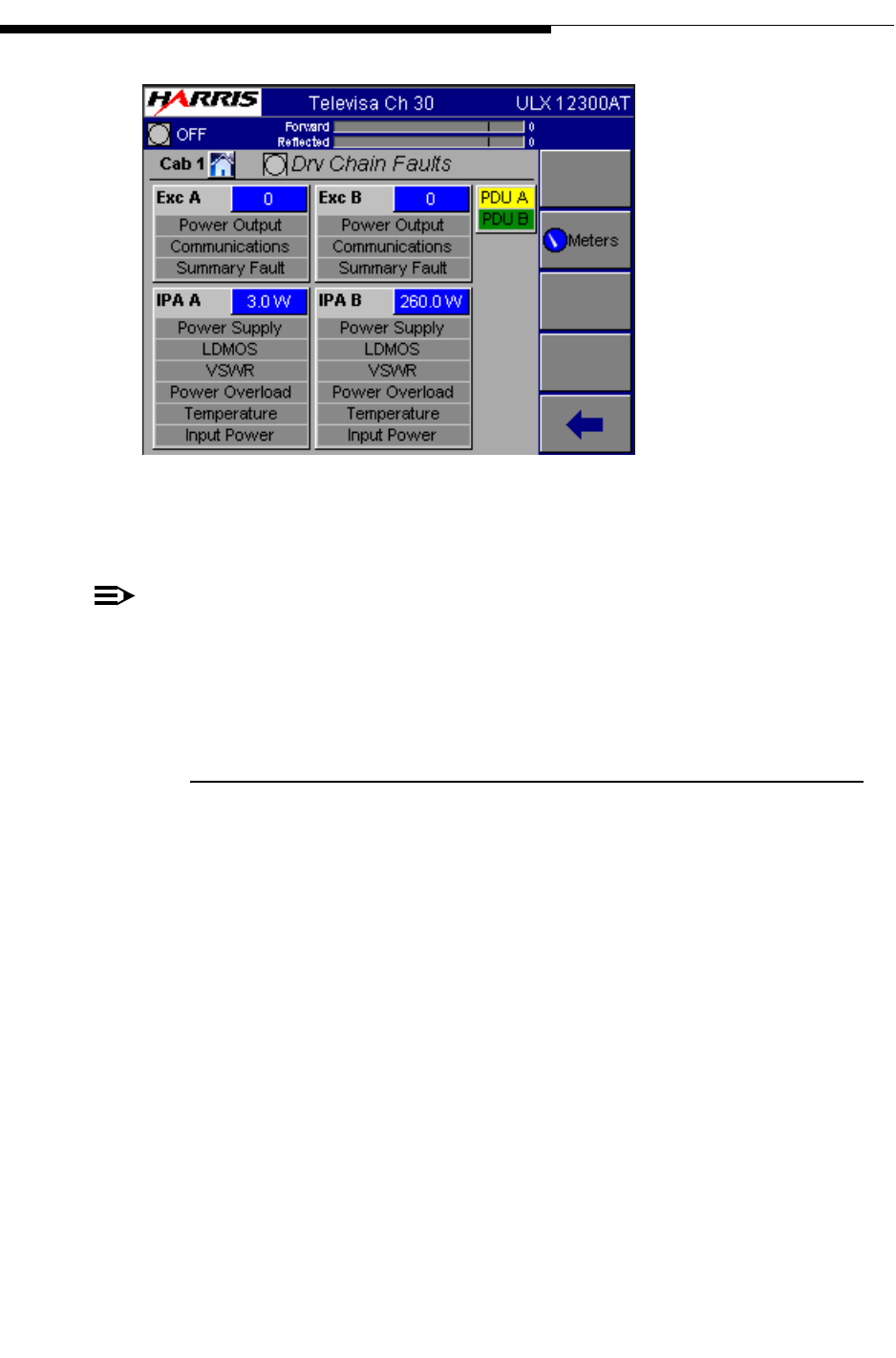
2.5.1 Drive Chain Faults
When the "Faults" button in Figure 2-5 is pressed, it will bring up the screen shown in
Figure 2-6. This screen is basically a fault display for exciters and pre-driver/IPA’s. For
more information on these faults and what to do if one should occur, refer to the M2X
exciter manual.
2/19/10 888-2715-001 2-11
WARNING: Disconnect primary power prior to servicing.
Section 2 Operation
Maxiva ULX ATSC Series
User Manual
Figure 2-6 Drive Chain Faults Screen
NOTE:
Exciter A is always factory installed as the upper exciter unit. The optional
exciter B is installed immediately above the TCU and below the top exciter unit
(see layout photo Figure 1-1 on page 1-2).
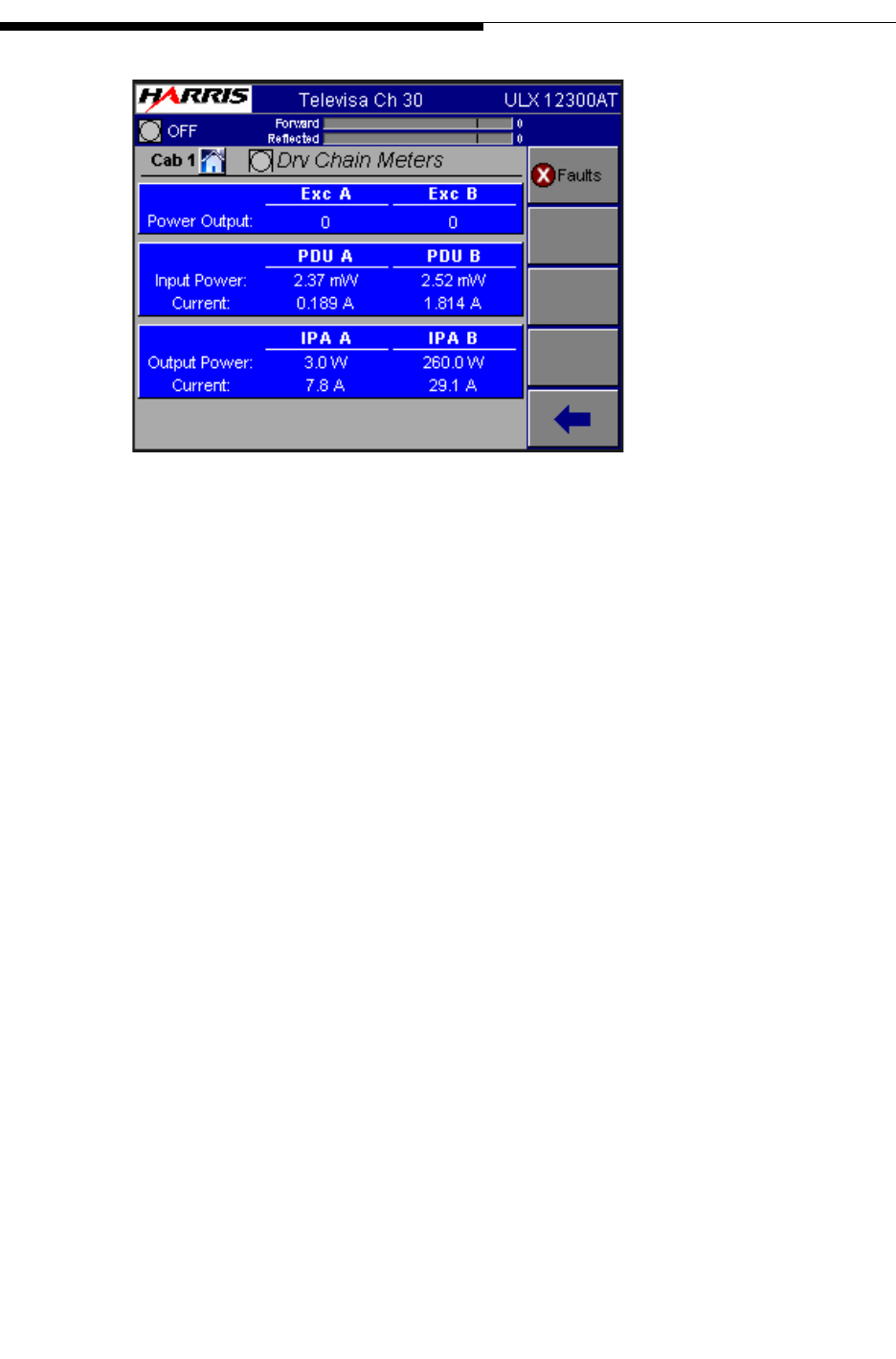
2.5.2 Drive Chain Meters
When the "Meters" button in Figure 2-6 is pressed, it will bring up the screen shown in
Figure 2-6. This screen displays input and output information for exciters and pre-
driver/IPA units.Current values for the pre-driver and IPA’s are also given.
To Figure 2-7
To Figure 2-5
2/19/10 888-2715-001 2-13
WARNING: Disconnect primary power prior to servicing.
Section 2 Operation
Maxiva ULX ATSC Series
User Manual
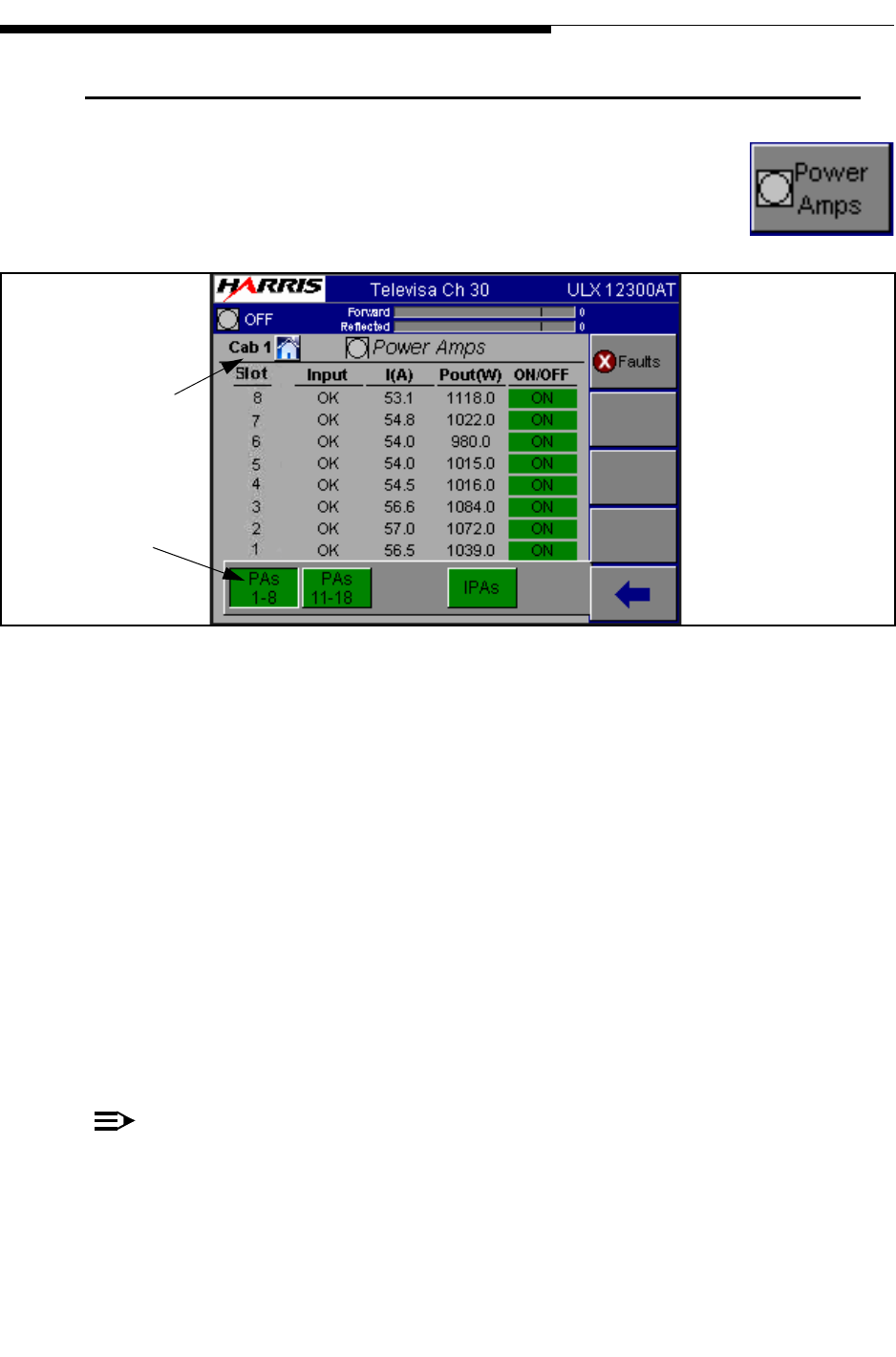
2.6 Power Amp Main Menu
If you press the Power Amps button on the HOME screen, it will take
you to the screen shown in Figure 2-8. The Power Amps Menu
structure is shown in Figure 2-24 on page 2-29.
Figure 2-8 Power Amps Screen
(PA Cabinet 1 ULX12300AT shown)
This screen shows the current and forward power for individual PA modules in the
indicated cabinet. Additional modules in the same cabinet are viewed by selecting the
PA’s 1-8 or 11-18 buttons in the lower left portion of the bottom of the screen. The PA,
Input and On/Off indications on the screen are also status indicators with 3 possible
states indicated:
a. OK - Green background
b. Fault - Red background
c. OFF - The background is gray.
The On/Off field will can be used to toggle individual amplifier modules on or off as
needed.
NOTE:
For multi-cabinet Maxiva Series transmitters (ULX13400 - ULX36900) the cabi-
net select buttons are located to the right on the screen. Selecting "Next Cabinet"
will allow viewing of information for the next cabinet. Once the desired cabinet
is selected, submenus are navigated in the same way as the others cabinets’.
To Figure 2-9
To Figure 2-4
PA Section
Select
Viewed Cabinet
2-14 888-2715-001 2/19/10
WARNING: Disconnect primary power prior to servicing.
Section 2 Operation
Maxiva ULX ATSC Series
User Manual
NOTE:
Always be sure that you are accessing the desired cabinet number. The cabinet
being viewed is indicated in the upper left corner of the screen.
To get detailed information on a particular PA Module, press the Faults button on the
right section of the screen. The Faults button will take you to the PA Faults screen
shown in Figure 2-9.
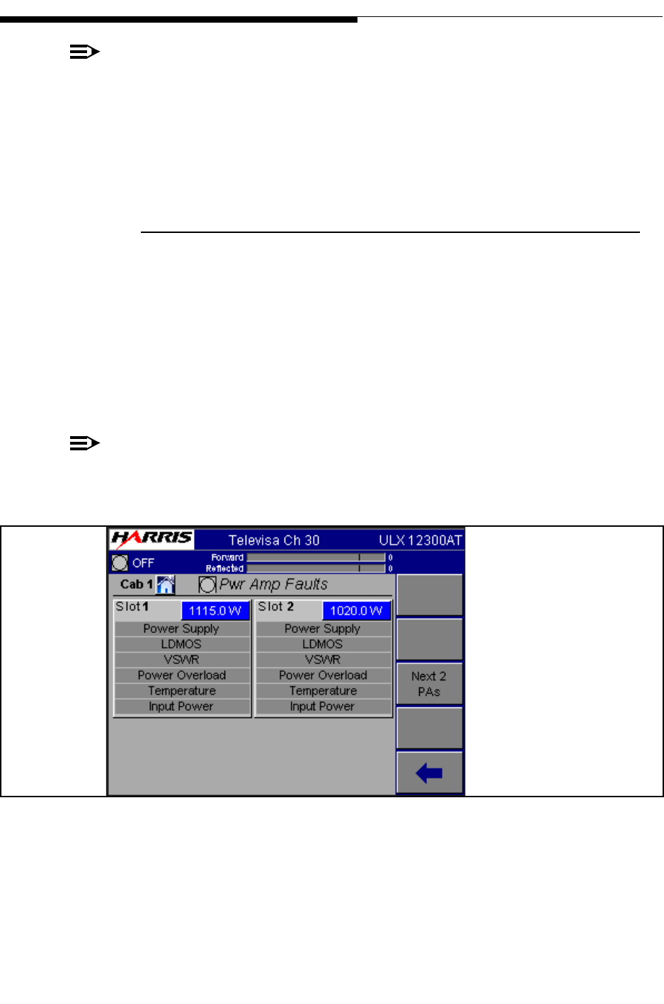
2.6.1 PA Faults
This screen is basically a list of all faults monitored in each PA Module.
• An active fault will be highlighted in RED
• A warning condition will be highlighted in YELLOW.
The PA Faults screen in Figure 2-9, shows that PA Module #1, in PA Cabinet #1 has no
faults and 1 temperature warning. It also shows a power supply fault on module 3 and
an input power warning on module 4.
NOTE:
For a detailed explanation of all PA Faults in Figure 2-9 refer to Section 6, Diag-
nostics.
Figure 2-9 PA Faults Screen (PA Module 1 Selected)
PA Modules will fault off at 200W reflected power. Also, it will display a temperature
fault at 65° C ambient temperature (measured by a thermistor on the monitor board) or
90° C pallet temperature.
To Figure 2-8
2/19/10 888-2715-001 2-15
WARNING: Disconnect primary power prior to servicing.
Section 2 Operation
Maxiva ULX ATSC Series
User Manual
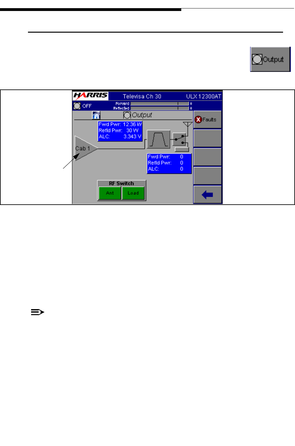
2.7 Output Main Screen
If you press the Output button on the HOME screen, it will take you to
the screen shown in Figure 2-10. The Output Menu structure is shown
in Figure 2-23 on page 2-27.
Figure 2-10 Output Screen
The main Output screen is has 3 main areas:
• RF Output System - This panel gives the total system Forward and Reflected
power, measured after the filter. It also has a VSWR and Foldback status
indications with backgrounds that are red for fault or yellow for warning. A
VSWR fault is indicated when the system VSWR is > 1.9:1. Foldback
warning is indicated when system VSWR is > 1.4:1
NOTE:
Both VSWR fault and foldback levels are adjustable via software.
• Power Amplifier Cabinet - Amplifier cabinet icons (triangle) give a status
indication of OK (green) or Fault (red) along with cabinet Forward and
Reflected power (before the filter) for each cabinet.
• Output Control - The control area at the bottom of the screen is used to
control an external RF switch so that the transmitter can be switched from
Antenna to the Test Load. The diagram indicates the position of the RF
switch based on micro-switches located on the switch.
To Figure 2-11
To Figure 2-4
Cabinet Indicators
2-16 888-2715-001 2/19/10
WARNING: Disconnect primary power prior to servicing.
Section 2 Operation
Maxiva ULX ATSC Series
User Manual
NOTE:
If the load interlock is open and the transmitter is switched to the "Test Load"
position, the transmitter output will be muted. If a test load interlock is not used
the appropriate connection on the interlock connector on the customer I/O panel
must be jumpered. For more information see UAX technical manual section two.
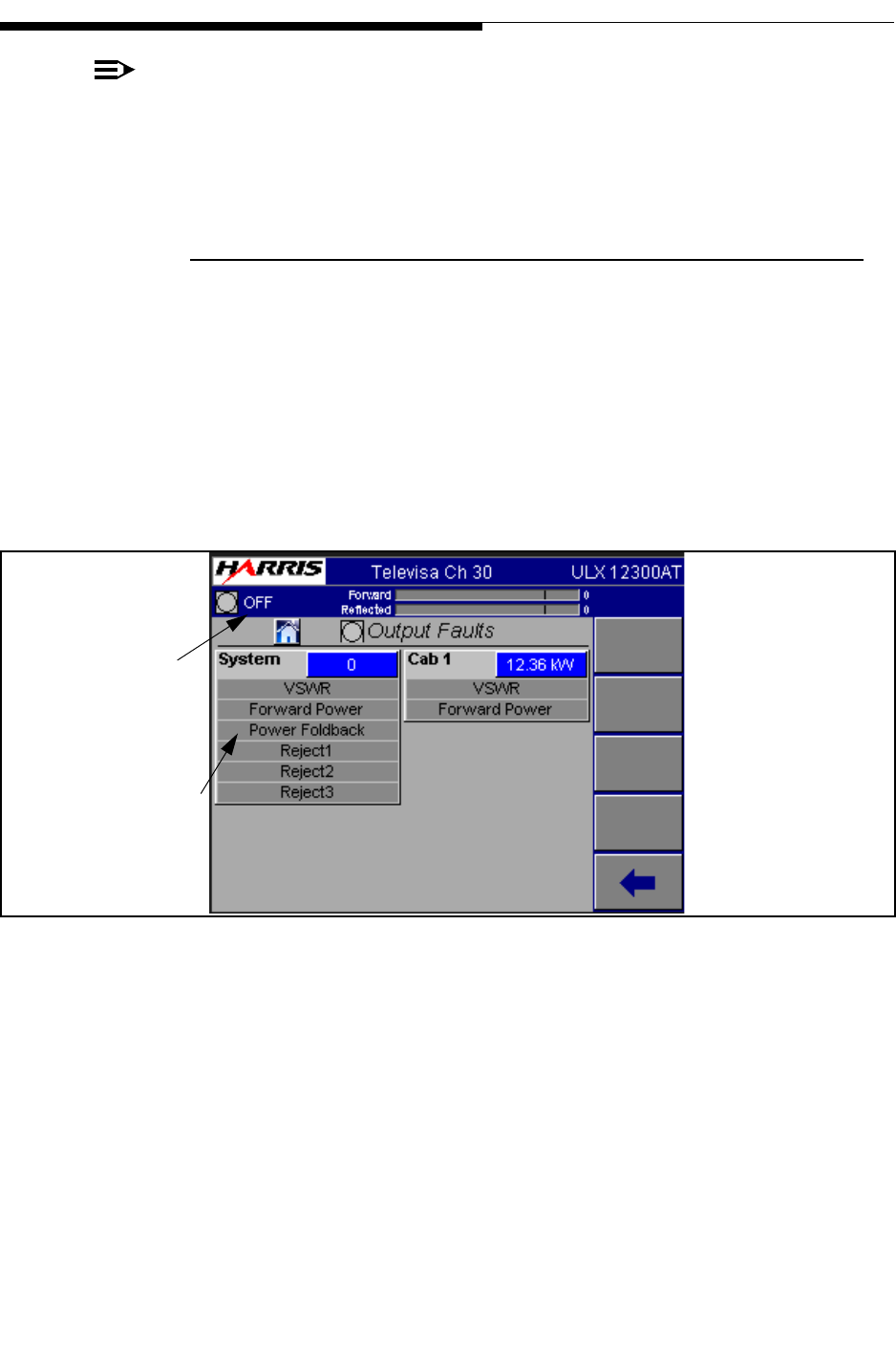
2.7.1 Output Faults
This screen shows faults which are considered Cabinet or System level such as VSWR,
Power High, foldback etc....
• An active fault will be highlighted in RED
• A warning condition will be highlighted in YELLOW
A detailed explanation of each of these faults is given in Section 6, Diagnostics.
Figure 2-11 Output Faults Screen
To Figure 2-10
ON becomes
ON/FB in fold-
back condition.
Background turns
yellow in foldback.
2/19/10 888-2715-001 2-17
WARNING: Disconnect primary power prior to servicing.
Section 2 Operation
Maxiva ULX ATSC Series
User Manual
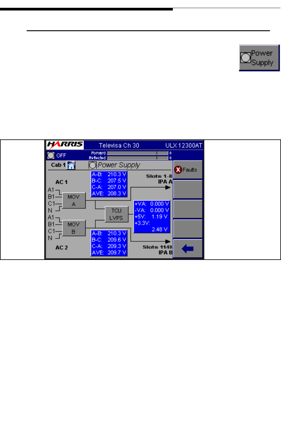
2.8 Power Supply Main Menu
If you press the Power Supply button on the GUI screen it will take you
to the screen shown in Figure 2-12. The Power Supply Menu structure
is shown in Figure 2-24 on page 2-29.
This is the power supply metering screen for both the low voltage power supply units
(in the TCU) and the AC Mains. It also allows access to Power Supply Fault screens:
• PS Faults - Fault list and status
• Next Cabinet - Access to PS screens on other cabinets if applicable.
Figure 2-12 Power Supply Screen
To Figure 2-13
To Figure 2-5
2-18 888-2715-001 2/19/10
WARNING: Disconnect primary power prior to servicing.
Section 2 Operation
Maxiva ULX ATSC Series
User Manual
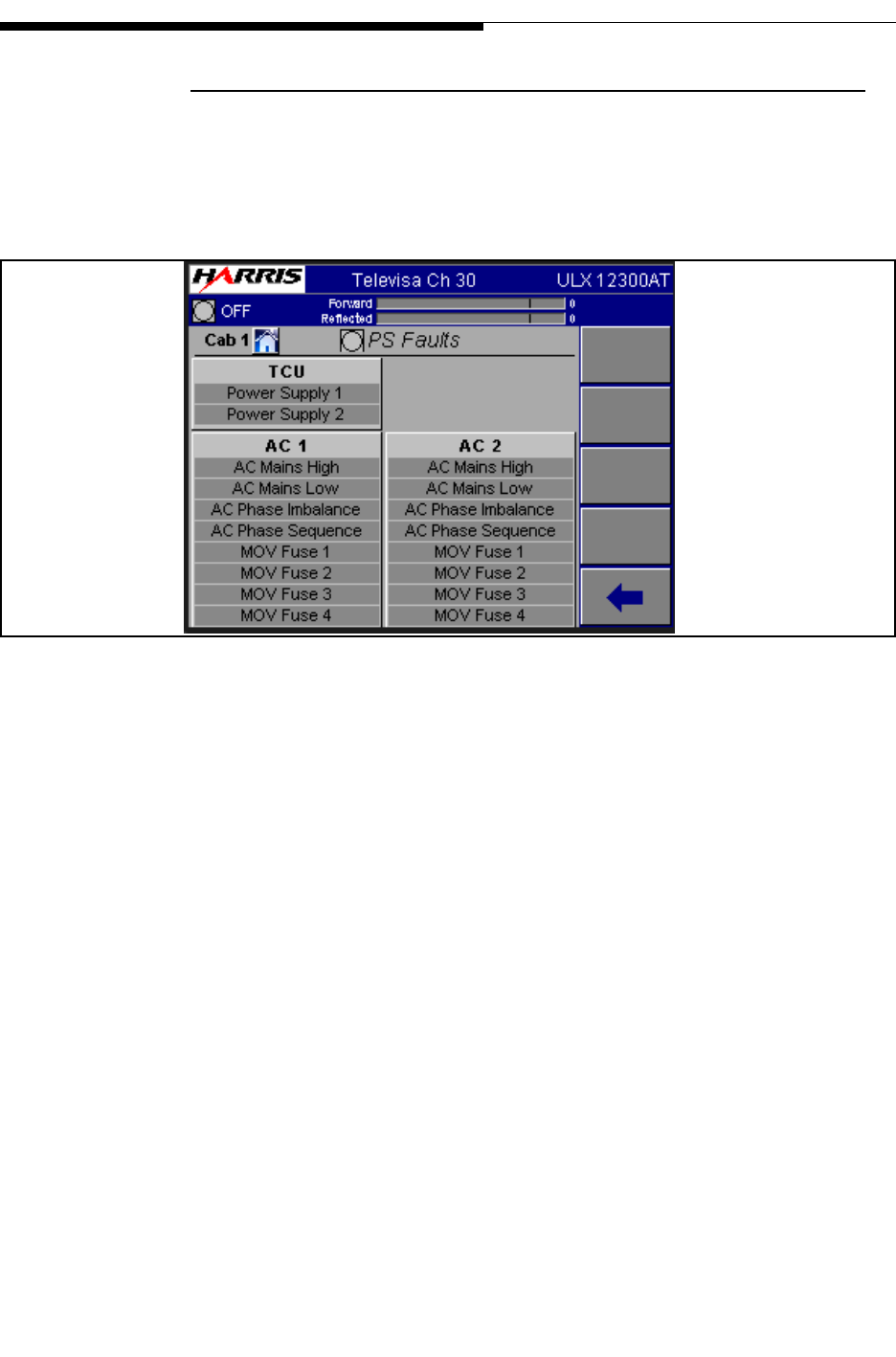
2.8.1 PS Faults
This is the PS (power supply) Faults screen which lists of all of the monitored power
supply faults for the AC mains and low voltage power supplies. An active fault will be
highlighted in RED, while a warning condition will be highlighted in YELLOW. For a
detailed explanation of these faults, refer to Section 6, Diagnostics.
Figure 2-13 PS Faults Screen
To Figure 2-12
2/19/10 888-2715-001 2-19
WARNING: Disconnect primary power prior to servicing.
Section 2 Operation
Maxiva ULX ATSC Series
User Manual
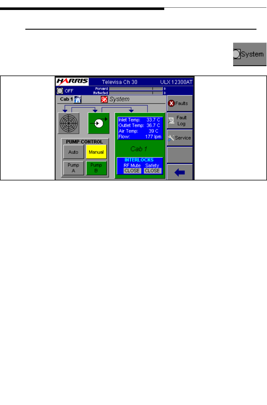
2.9 System Main Menu
If you press the System button on the GUI screen, it will take you to the
screen shown in Figure 2-14. The System Menu structure is shown in
Figure 2-24 on page 2-29.
Figure 2-14 System Main Menu
This screen contains the System Main Menu which gives overall status information and
access to additional System screens. This includes:
a. CAB1 - Provides coolant temperatures, air temperatures and coolant flow (liters
per minute). The CAB1 block also provides the status of the RF Mute and Safety
Interlocks. Interlocks can read Open (red background) or Closed (gray back-
ground)
b. Pump Status - Pump icon has a green background color if no faults are present or
a red background color if faults are active. For more information on faults press
"Faults"
c. Pump Control - Pump A & Pump B for dual pump systems are indicated. This
panel would be grayed out (inactive) for single pump systems. The active pump
will have a green background. Pumps can be switched from this screen, by
pressing A or B only if the pump control panel switch is in the REMOTE mode.
Placing the pump control panel in LOCAL mode will disable pump selection on
the System GUI screen. For additional information on LOCAL operation and the
pump control panel see "1.2.8.1 Cooling System Control Panel" on page 1-15.
AUTO or MANUAL can also be selected here. Selecting AUTO allows
automatic switchover in case of pump failure in dual pump systems. AUTO is the
normal operating mode if the system has dual pumps.
To Figure 2-15
To Figure 2-16
To Figure 2-17
To Figure 2-4
2-20 888-2715-001 2/19/10
WARNING: Disconnect primary power prior to servicing.
Section 2 Operation
Maxiva ULX ATSC Series
User Manual
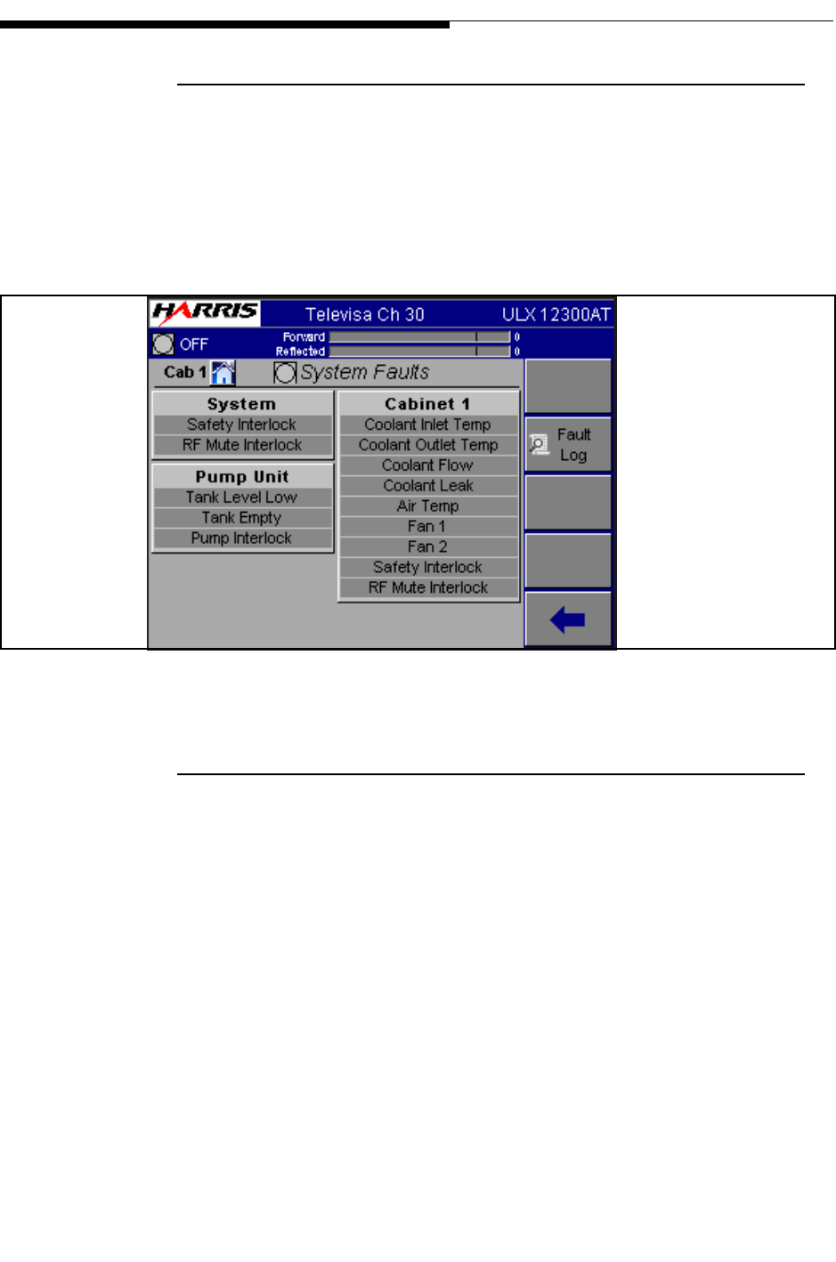
2.9.1 System Faults
This screen is accessed by pressing the Faults button on the System screen. An active
fault condition is highlighted in RED while a warning condition is highlighted in
YELLOW.
For more information on these faults refer to Section 6, Diagnostics.
Figure 2-15 System Faults Screen
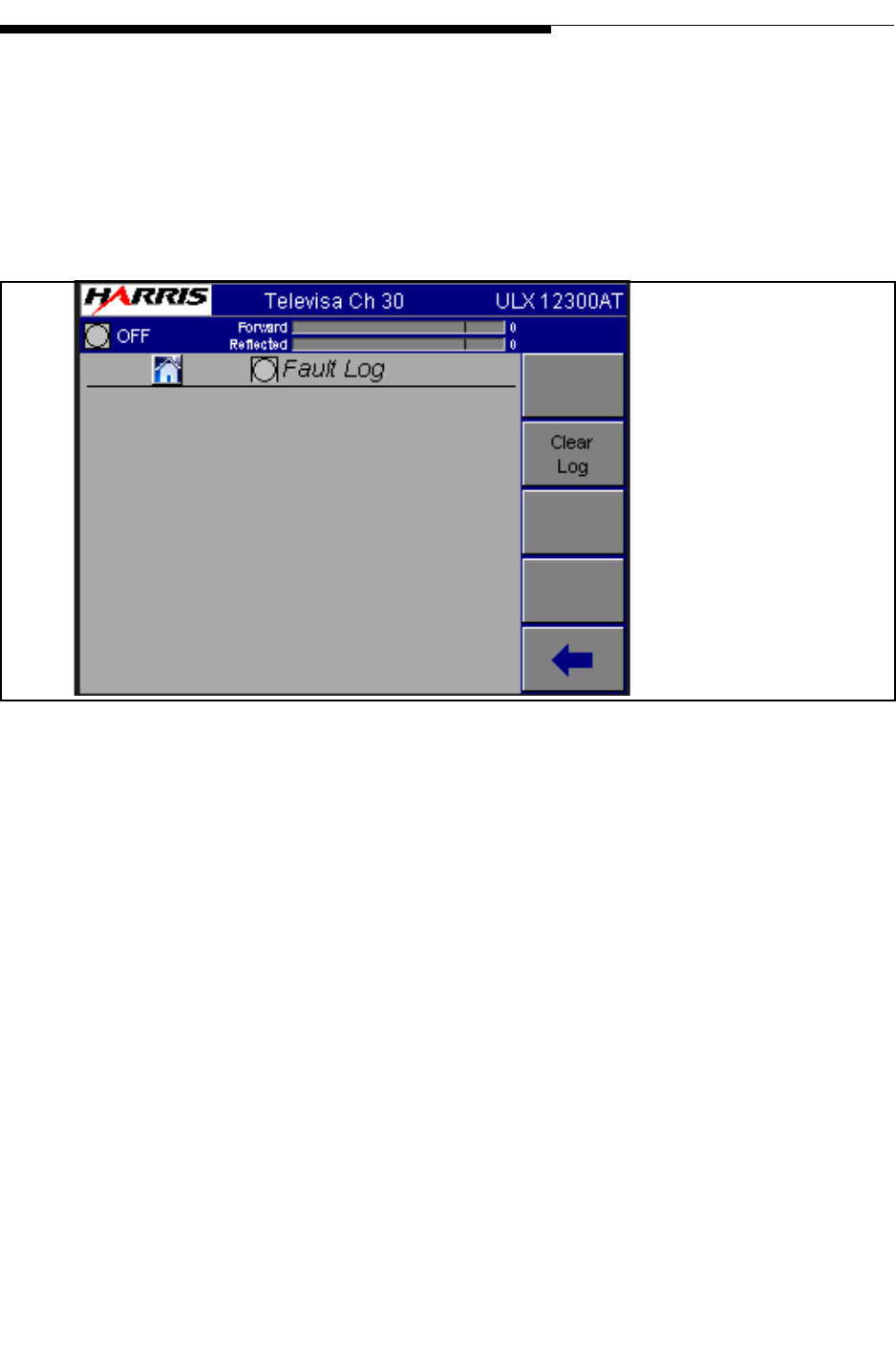
2.9.2 System Fault Log
This screen is accessed by pressing the System Fault Log button on the System screen
in Figure 2-14 on page 2-19. It is a complete listing of all transmitter and system faults
in the order in which they occurred. It can hold up to 99 faults and then becomes a FIFO
(First IN - First Out) memory buffer, with the latest fault entry on top. Active Faults
will be highlighted and cannot be reset. All other faults will be cleared when the RESET
button is pressed. Use the NEXT and PREVious buttons to view the entire list.
A complete listing of all faults which can show up in this log, along with a brief
explanation of each fault, is given in the following tables in Section 6, Diagnostics.
• Table 3-1, “Maxiva Drive Chain Fault List,” on page 3-5
• Table 3-2, “PA and IPA Module Fault List,” on page 3-7
• Table 3-3, “Power Supply Faults List,” on page 3-8
To Figure 2-14
2/19/10 888-2715-001 2-21
WARNING: Disconnect primary power prior to servicing.
Section 2 Operation
Maxiva ULX ATSC Series
User Manual
• Table 3-4, “Output Faults List,” on page 3-10
• Table 3-5, “System Faults List,” on page 3-12
These tables are a quick reference list and in most cases is all that is required for
advanced user to diagnose the problem. However, detailed information on each of these
faults is also given in context with the fault page where it originated, also in Section 6.
Figure 2-16 System Fault Log Screen
To Figure 2-14
Note:
Date format is
DD/MM/YY
Press to clear all faults
2-22 888-2715-001 2/19/10
WARNING: Disconnect primary power prior to servicing.
Section 2 Operation
Maxiva ULX ATSC Series
User Manual
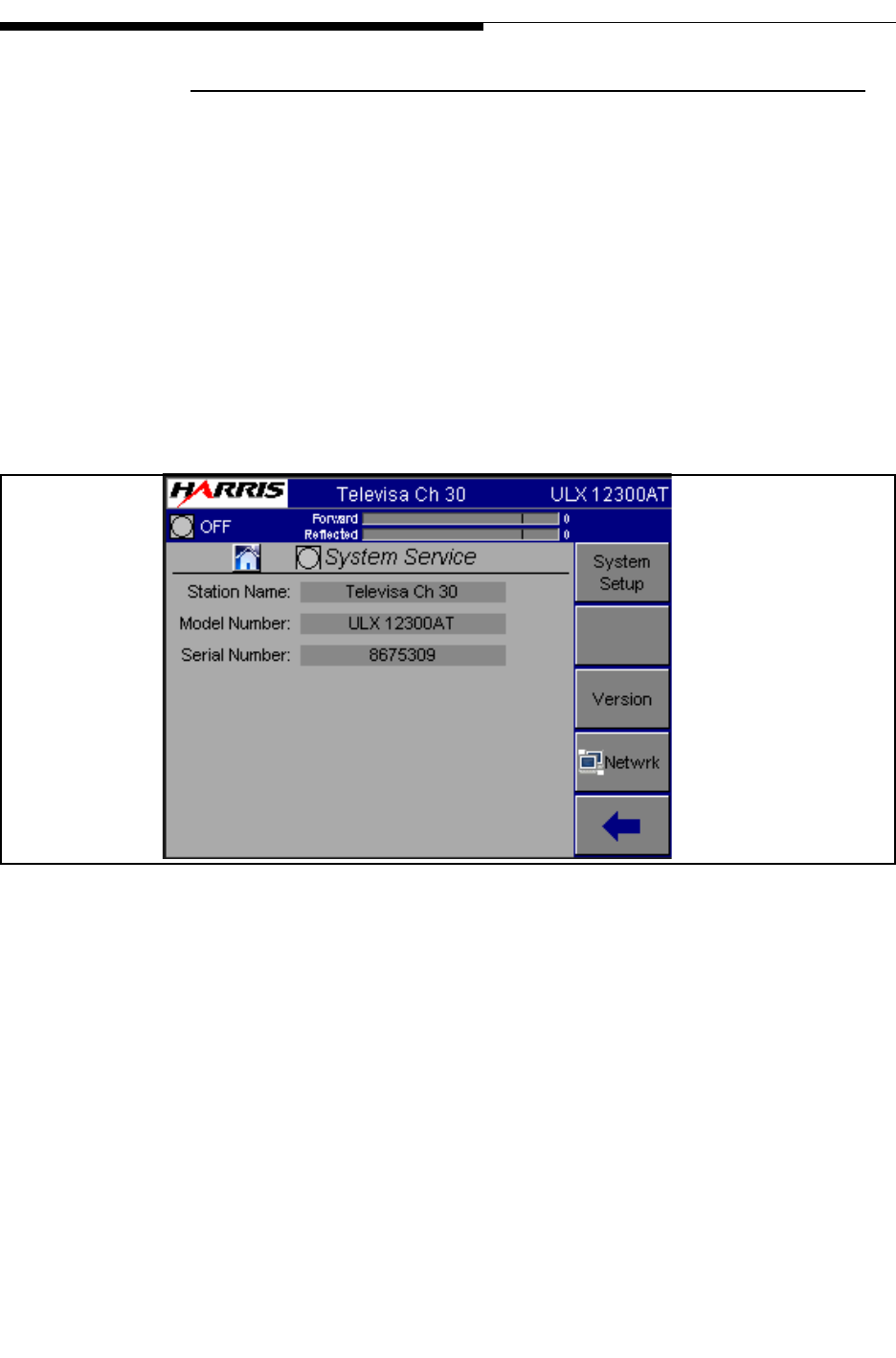
2.9.3 System Service
This screen provides a way to change 3 pieces of information which are then used
throughout the GUI. The System Service screen us shown in Figure 2-17 on page 2-22.
•Station Name: This can be up to 24 characters and will appear at the top of every
GUI screen
•Model Number: This value is entered at the factory. The model number chosen must
match the transmitter name plate. It is used to gray out portions of the GUI screens
which are not used by some models.
•Serial Number: This is entered at the factory. Refer to this number if calling for sup-
port.
Figure 2-17 System Service Screen (Remote)
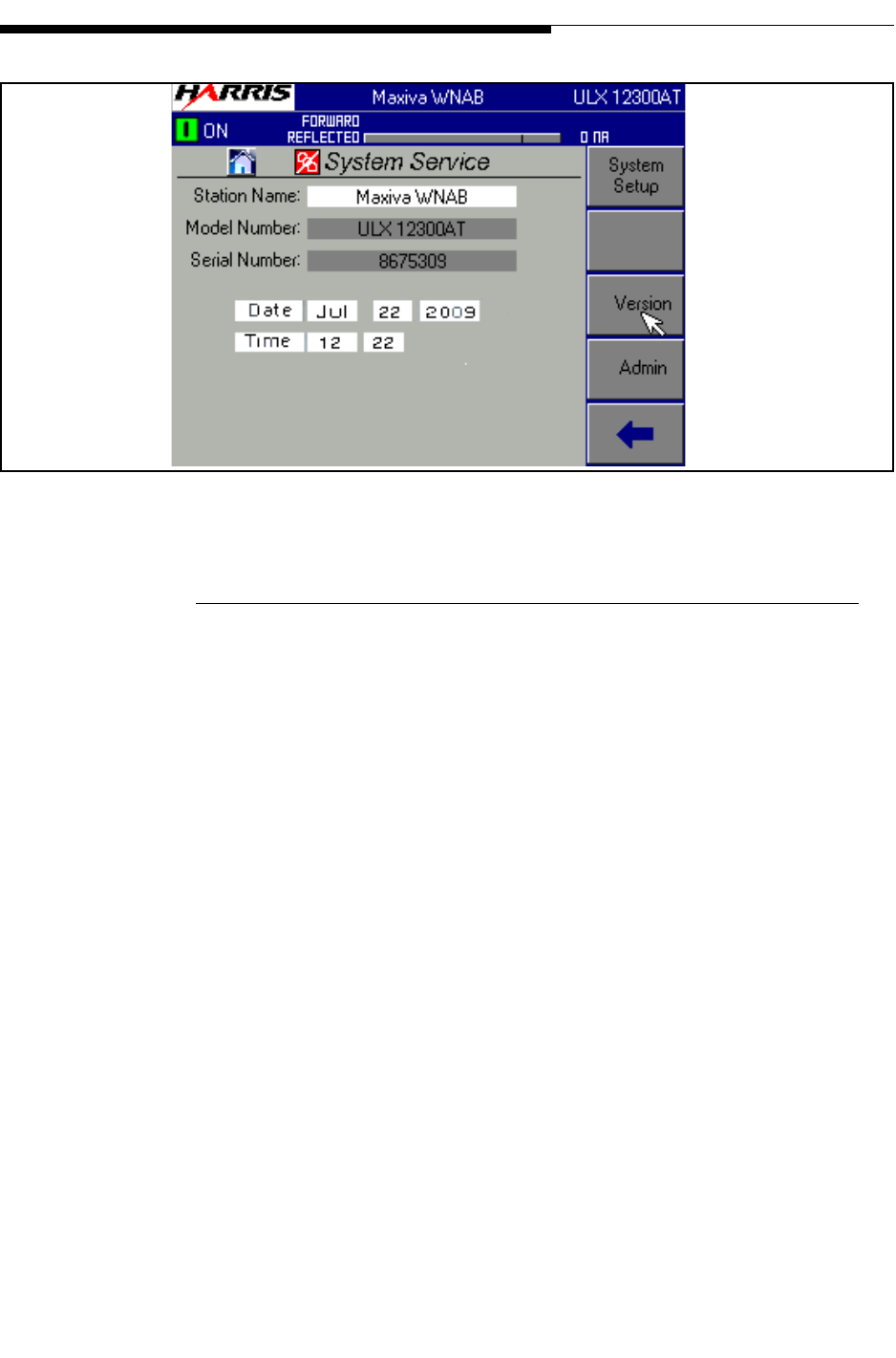
The System Service screen varies depending on whether it is viewed on the local GUI
screen or remotely via web browser. The local screen shown in Figure 2-18 on page 2-
23 contains additional entry windows to allow manual entry of date and time values.
The TCU will automatically set date and time values at turn on if it is connected to a
network.
To Figure 2-20
To Figure 2-23
To Figure 2-20
To Figure 2-22
2/19/10 888-2715-001 2-23
WARNING: Disconnect primary power prior to servicing.
Section 2 Operation
Maxiva ULX ATSC Series
User Manual
Figure 2-18 System Service Screen (Local)
2.9.3.1 Admin Setup (Local GUI Only)
The Admin screen is accessed by pressing the Admin button shown on the Local GUI
System Service screen shown in "Figure 2-18 System Service Screen (Local)" on page
2-23. The following parameters are accessed via the System Service Admin screen.
•Login: Allows access as Guest, Operator or Expert. Guest level allows user to view
screens but does not allow adjustments. Operator allows viewing and operational
adjustments. Expert allows viewing, operational and maintenance adjustments.
- Local GUI login is admin. Web browser login is admin.
•Password: Allows user password entry. There are different login and passwords for
local and web browser GUI usage. The default logins and password from the factory
are:
- Local GUI passwrord is harris. Web browser login is harris2009.
•Expire: Sets the expiration time for the user access level.
•LCD Contrast: The screen contrast can be adjusted dynamically to allow for differ-
ent room lighting by change the percentage setting.
•User (administrators only): This area is used to enter ID’s and passwords for the
various user levels.
•Reboot: This button will reboot the TCU. The transmitter will stay on the air. Reboot
takes about 2 minutes
To Figure 2-20
To Figure 2-19
To Figure 2-20
To Figure 2-22
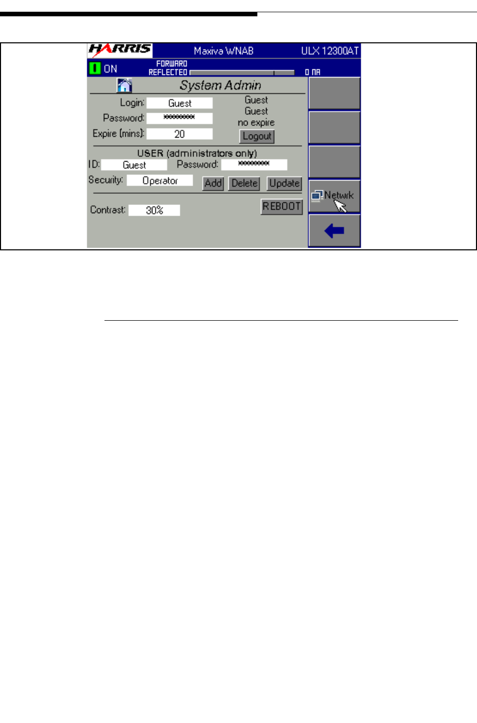
2-24 888-2715-001 2/19/10
WARNING: Disconnect primary power prior to servicing.
Section 2 Operation
Maxiva ULX ATSC Series
User Manual
Figure 2-19 System Admin Screen
2.9.3.2 System Setup
•Sys Pwr Out (W): Set this value to the system nominal power output. This value
determines the 100% level on the GUI power out bar.
•Center Freq (MHz): Enter the center frequency for the desired operational channel.
This only sets the transmitter frequency. It doesn’t set the exciter frequency.
• Modulation Type: Select the system modulation type from the values displayed in
the box.
•AC Line Volt (VAC): Set this to the nominal AC line voltage at the transmitter site.
•Number of Exciters: Set this to either 1 or 2 depending on how many exciters are in
the transmitter.
•Number of Cabinets: Set this to the number of PA cabinets in the system.
•System Setup Entry: Enter a number from 1 to 8 in this field. For example if you
want to set up the transmitter for CH29 and store it in entry 3, you enter 3 in the Sys-
tem Setup Entry. This will recall the data for entry 3. If no data is there, defaults will
be loaded. Once all the calibrations for channel 29 are done you press SAVE SETUP.
This will save the data to entry 3.
To Figure 2-20
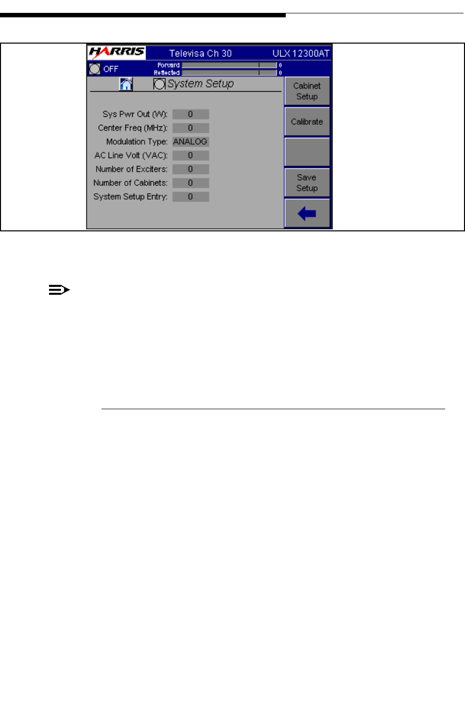
2/19/10 888-2715-001 2-25
WARNING: Disconnect primary power prior to servicing.
Section 2 Operation
Maxiva ULX ATSC Series
User Manual
Figure 2-20 System Setup Screen
NOTE:
The Save Setup button allows storage of up to eight setups for the purpose of
N+1 operation. All the calibrations for the transmitter are saved in the MCM
module. This means the transmitter can change to anyone of 8 channels and be
fully calibrated by simply recalling the set up entry. The N+1 controller will send
the set up the entry that needs to be recalled, as well as set the exciter frequency.
2.9.3.3 Cabinet Setup
•Cab Pwr Out (W): Set cabinet output power here. This is the power out of the cabi-
net before the combiner or filter. This needs to be set for each cabinet. Sets cabinet
nominal power used to set ALC level. Maximum cabinet power is limited to 10%
over this value.
•Number of PA’s: Enter the number of PA modules in the selected cabinet. This needs
to be set for each cabinet.
• Number of IPA’s: Enter the number of IPA modules in the selected cabinet. This
needs to be set for each cabinet.
•Cooling Pumps: Set this to either 1 or 2 depending on how many pumps are in pump
module/heat exchanger for this cabinet. This needs to be set for each cabinet.
To Figure 2-21
To Figure 2-17
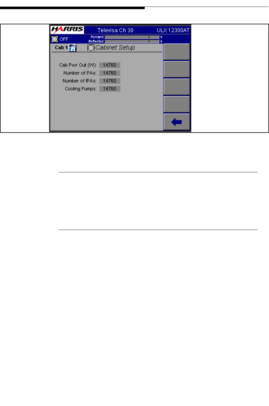
2-26 888-2715-001 2/19/10
WARNING: Disconnect primary power prior to servicing.
Section 2 Operation
Maxiva ULX ATSC Series
User Manual
Figure 2-21 Cabinet Setup Screen
2.9.3.4 System and Cabinet Power Calibrate
See the UAX technical manual Section 5 for the procedure that utilizes these screens.
2.9.3.5 System Version Screen
This screen shows the software revision for the TCU controllers. This information
should be known before calling for technical support.
To Figure 2-17
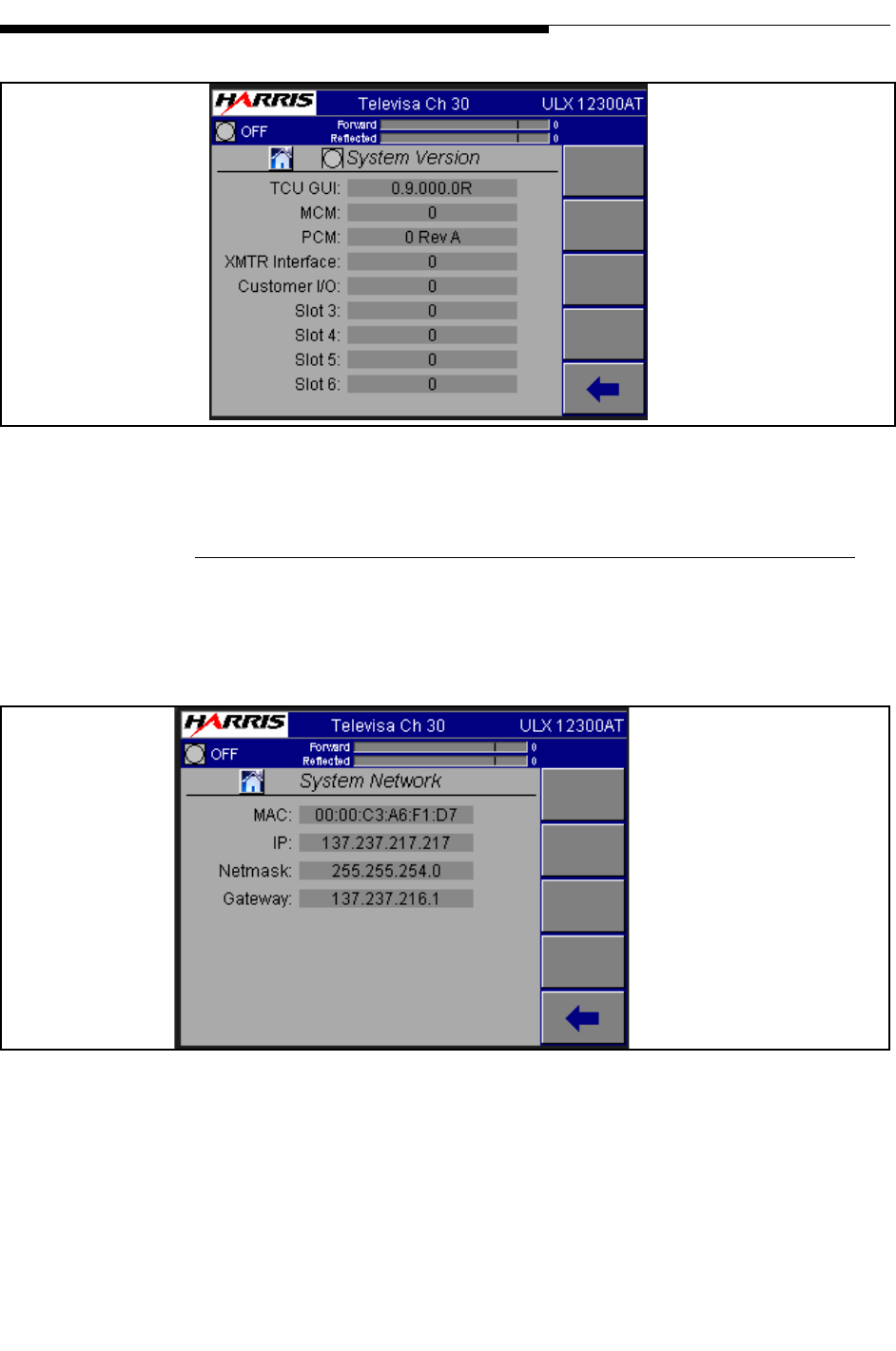
2/19/10 888-2715-001 2-27
WARNING: Disconnect primary power prior to servicing.
Section 2 Operation
Maxiva ULX ATSC Series
User Manual
Figure 2-22 System Version Screen
2.9.3.6 System Network Screen
This screen provides information about network settings. MAC, IP, Netmask and
Gateway settings are given.
Figure 2-23 System Network Screen
The System Network screen when viewed from the local GUI has an additional button
called Save & Restart Network. When a change is made to one of the network
parameters (IP address, mask, etc.) the networking system has to be restarted before the
To Figure 2-17
To Figure 2-17

2-28 888-2715-001 2/19/10
WARNING: Disconnect primary power prior to servicing.
Section 2 Operation
Maxiva ULX ATSC Series
User Manual
change is implemented. Save & Restart saves the change and restarts the network
system so the change is made permanent and the new parameters become active.
2.10 GUI Menu Structures
Figure 2-24 on page 2-29 shows the menus which can be accessed on the GUI. This
menu tree may be helpful when learning to navigate the screens. The blocks on the left
represent the main menus which can accessed using one of the 5 software buttons on the
right side of the GUI HOME Page. Each successive level (to the right) represents
software buttons which will show up on the right side of the GUI submenu screens.
NOTE:
Multi-cabinet Maxiva Series transmitters will require an extra button press at the
top level menus to select the desired cabinet.
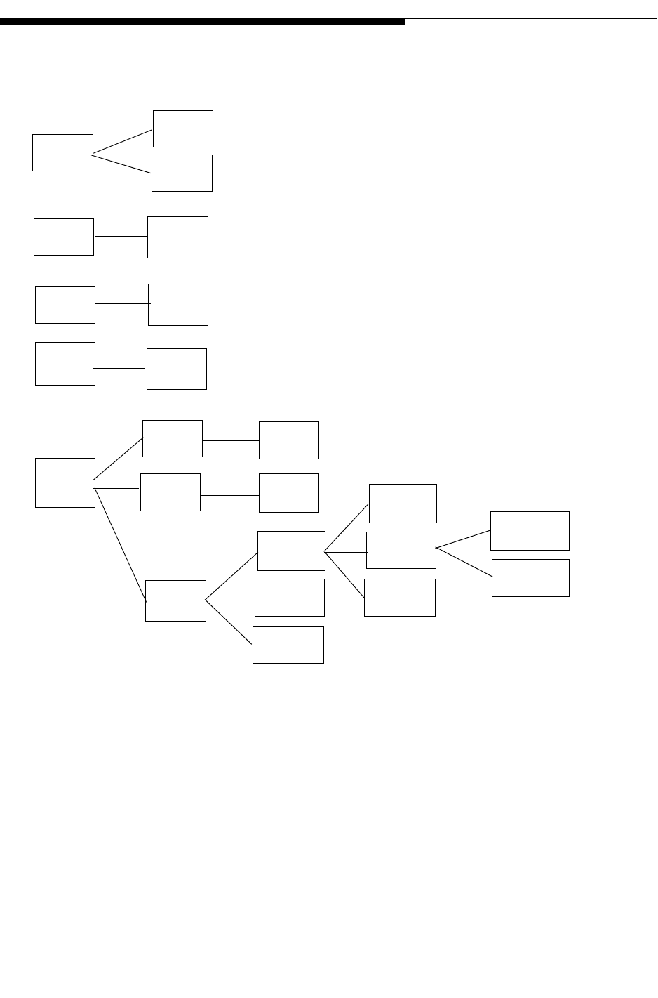
2/19/10 888-2715-001 2-29
WARNING: Disconnect primary power prior to servicing.
Section 2 Operation
Maxiva ULX ATSC Series
User Manual
Figure 2-24 GUI Menu Tree
Drive
Chain
Power
Amps
Output
Power
Supply
System
Faults
Meters
Faults
Faults
Faults
Faults
Logs
Service
Faults
Log
Clear
Log
System
Setup
Version
Network
Cabinet
Setup
Calibrate
Save
Setup
Cabinet
Calibrate
Trips

2-30 888-2715-001 2/19/10
WARNING: Disconnect primary power prior to servicing.
Section 2 Operation
Maxiva ULX ATSC Series
User Manual
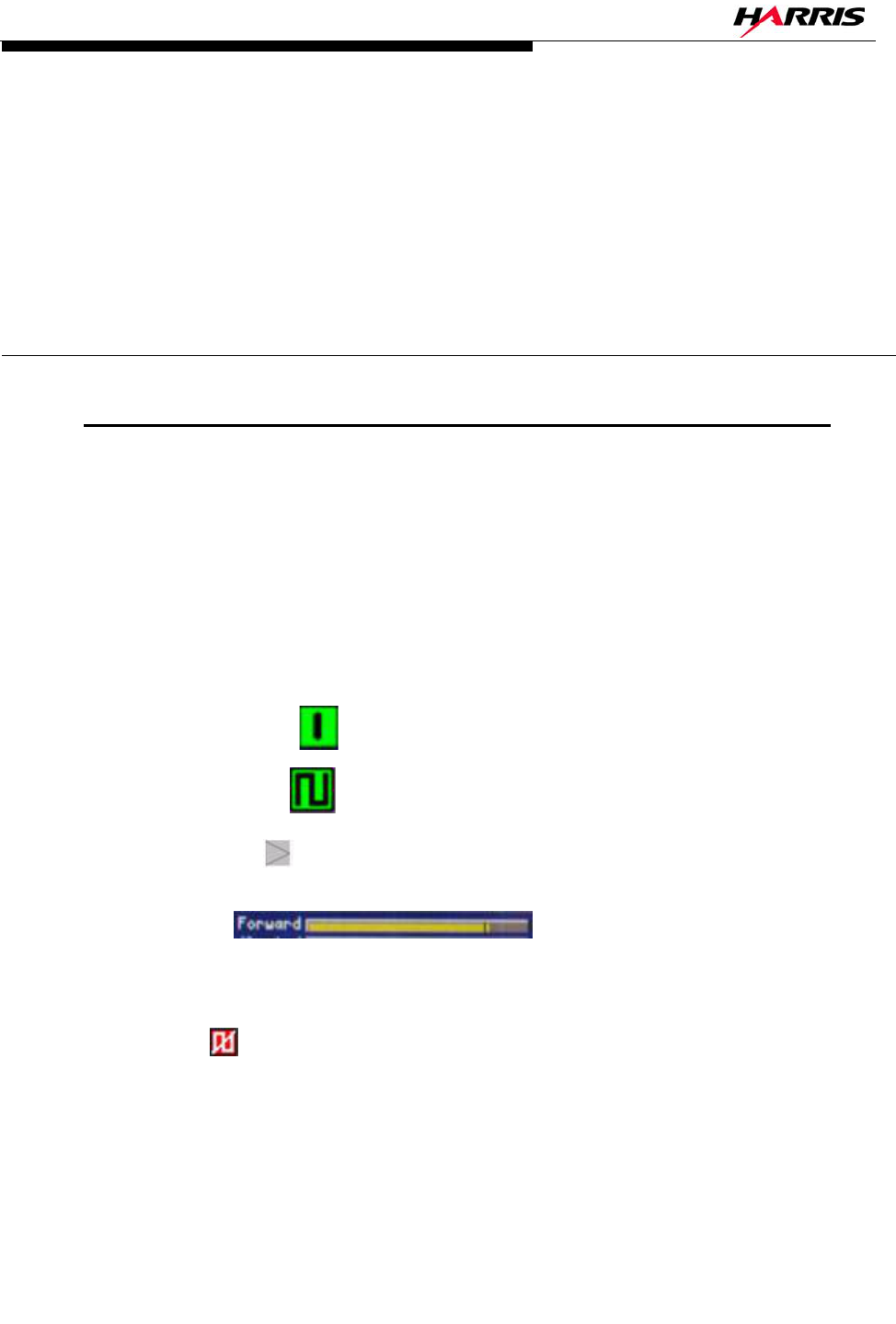
2/19/10 888-2715-001 3-1
WARNING: Disconnect primary power prior to servicing.
Maxiva ULX ATSC Series
User Manual
Section 3
Diagnostics 3
3.1 Introduction
This section contains diagnostic and troubleshooting information for the ULX series
UHF transmitter. Included is a complete description of all faults which can be displayed
via the transmitter front panel TCU display or GUI (Graphical User Interface). Due to
the complexity of the transmitter control system and the extensive use of surface mount
components, the scope of this diagnostics section is to isolate the problems down to a
PC board or module level which can then be easily exchanged.
The GUI buttons and icons use a symbol and color code system. Some examples using
the triangle shape are given below. The other shapes operate similarly.
a. Green with a 1 - - ON and operating normally.
b. Green symbol - - ON and operating normally.
c. Light Gray - - "Grayed Out" - Not communicating or not available.
d. Yellow - Warning - A non-critical sub-
system or parameter is out of tolerance and should be addressed by engineering
personnel.
e. Red - - Critical Fault - This could be a sub-system fault in which the sub-
system is muted or shut off (such as a PA Module) or could be a system level fault
which could mute or shut the transmitter off.
When a fault occurs one or more of the 5 LED’s on the TCU will illuminate RED. To
track down the cause of the fault, begin by looking at the TCU Home screen and the

3-2 888-2715-001 2/19/10
WARNING: Disconnect primary power prior to servicing.
Section 3 Diagnostics
Maxiva ULX ATSC Series
User Manual
software buttons along the right side as shown in Figure 2-4 on page 2-7 another option
is to start by going to the System Log and seeing what faults have occurred and in what
order. If you are not familiar with GUI navigation, refer to Section 3.
3.2 GUI System Log
The GUI contains a System Log which is a listing of all faults which have occurred. To
see the System Log press SYSTEM then SYSTEM LOG. This will bring up the screen
in Figure 3-1. The System Log gives the following information:
a. # - This gives the number of the fault. There can be up to 99 faults in the log, then
it is FIFO (First IN, First Out)
b. Fault Type - This is simply the name of the fault.
c. Time and Date - This gives the exact time and date that the fault occurred.
d. Active or Inactive - If the fault is highlighted in red, it is still active and cannot
be cleared. If the fault is not highlighted, then the fault is gone and can be cleared
if so desired.
Function Buttons:
a. RESET - Will erase all inactive faults in the log.
b. NEXT and PREV - These buttons allow you to scroll through the entire fault list
if necessary.
c. BACK - Will take you back to the System main menu.
NOTE:
Tables 6-1 and 6-2 give a complete listing of all possible faults in the Maxiva
transmitter. They also give a brief description of each fault, the trip point and the
transmitter action taken in response to the fault.
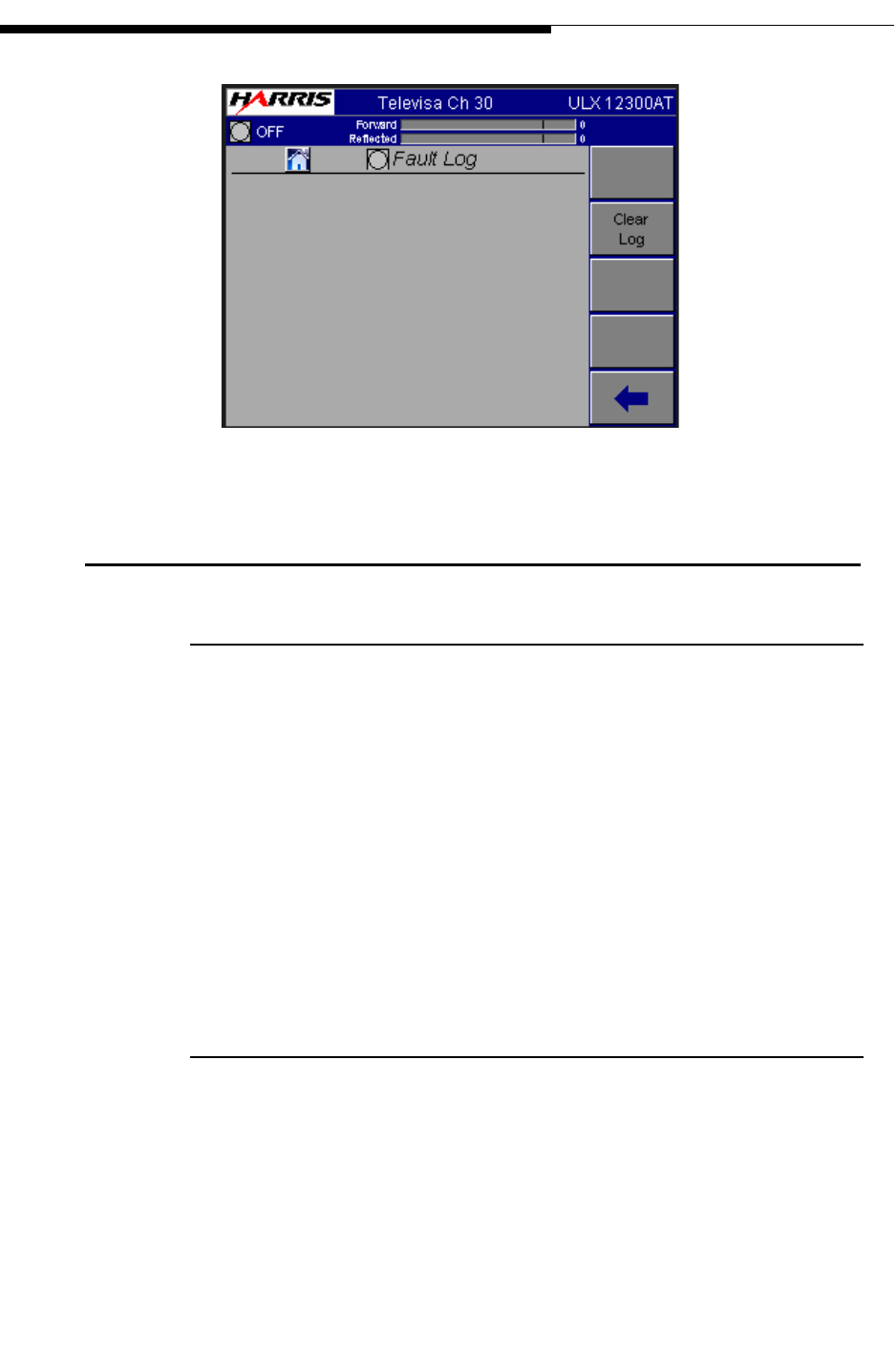
2/19/10 888-2715-001 3-3
WARNING: Disconnect primary power prior to servicing.
Section 3 Diagnostics
Maxiva ULX ATSC Series
User Manual
Figure 3-1 Fault Log Screen
3.3 Maxiva Three-Strike Fault Actions
3.3.1 Reflected Power Faults
The TCU monitors reflected power at the Cabinet output and at the System output.
When the reflected power level (typically 10% of the rated power or a 1.9:1 VSWR) is
exceeded the TCU generates an RF MUTE. If after three attempts to restart (three
strikes) subsequent faults occur, the transmitter will turn OFF and operator intervention
will be needed to turn it back ON. The three strike counter resets after 30 seconds with
no faults.
Reflected power faults that initiate a three strike procedure are:
• Cabinet Reflected Power
• System Reflected Power
3.3.2 Module Faults
Should a module failure occur (say a power glitch) the TCU will initiate a three-strike
action. This action will cause a reset of only the PA Module experiencing the fault and
not the entire transmitter.

3-4 888-2715-001 2/19/10
WARNING: Disconnect primary power prior to servicing.
Section 3 Diagnostics
Maxiva ULX ATSC Series
User Manual
The module three strike policy is:
• The TCU will try to restart the module three times within a 10 second
window. After that, if a fault is still present, the module will be turned OFF
until it receives the restart command from the Main Controller (ON
Command).
• There is a 3 second delay between restart attempts.
• The fault-strike restart process is the same as the system restart command, all
of the module faults will be reset.
• During the 10 second three-strike window, any of the nuisance faults will be
reported to the Main Controller.
These are the module faults which will be allowed three strikes:
• Over Voltage Pallet
• Under Voltage Pallet
• Over Temperature Module Controller
• Over Current Module Driver
• Over Temperature Pre-driver Heatsink
• Over Drive Module RF Input
• Over Drive Module RF Output
• Under Current Phase and Gain Board
• Over Current Phase and Gain Board
• Over Current Pallet
• Under Current Pre-Driver
• Over Current Pre-Driver
• Over Temperature Power Supply Board
• Low Voltage Output DC Converter
• Short Circuit
• High Module Reflected Power

2/19/10 888-2715-001 3-5
WARNING: Disconnect primary power prior to servicing.
Section 3 Diagnostics
Maxiva ULX ATSC Series
User Manual
3.4 Fault Tables
The following tables provide a listing of Maxiva Transmitter faults along with a brief
description, the fault level or threshold and the action taken by the transmitter.
Table 3-1 Maxiva Drive Chain Fault List
TYPE Description Fault Level or
Threshold Transmitter
Action Three
Strike Available
in Life
Support
IPA A Fault: Power
Supply, LDMOS,
VSWR, Power
Overload, Tempera-
ture, Input Power
The IPA can report
up to 6 faults via
their parallel con-
trol pins
Any one fault active IPA Switch to
alternate IPA if
in Auto Mode
YES YES
IPA B Fault: Power
Supply, LDMOS,
VSWR, Power
Overload, Tempera-
ture, Input Power
The IPA can report
upto 6 faults via
their parallel con-
trol pins
Any one fault active IPA Switch to
alternate IPA if
in Auto Mode
YES YES
PDU (Predriver) A
Fault
The Predriver cur-
rent is monitored
inside the PDU. A
fault is sent if it is
below the normal
minimum current.
Predriver current is
below TBD mA
IPA Switch to
alternate IPA if
in Auto Mode
NO YES
PDU Predriver B
Fault
The Predriver cur-
rent is monitored
inside the PDU. A
fault is sent if it is
below the normal
minimum current.
Predriver current is
below TBD mA
IPA Switch to
alternate IPA if
in Auto Mode
NO YES
Exciter A Power
Output
Exciter A power
level low
Trip point is 50% of
nominal. Trip point
adjustable by epot
Exciter Switch
to alternate
Exciter if in
Auto Mode
NO YES

3-6 888-2715-001 2/19/10
WARNING: Disconnect primary power prior to servicing.
Section 3 Diagnostics
Maxiva ULX ATSC Series
User Manual
Exciter B Power
Output
Exciter B power
level low
Trip point is 50% of
nominal. Trip point
adjustable by epot
Exciter Switch
to alternate
Exciter if in
Auto Mode
NO YES
EXCA NO COMMU-
NICATIONS
Exciter A not com-
municating with
transmitter main
controller
No serial communica-
tions traffic detected
Exciter Switch
to alternate
Exciter if in
Auto Mode
NO NO
EXCB NO COMMU-
NICATIONS
Exciter B not com-
municating with
transmitter main
controller
No serial communica-
tions traffic detected
Exciter Switch
to alternate
Exciter if in
Auto Mode
NO NO
EXCA Summary
Fault
Exciter A reports a
summary fault
Exciter Switch to alter-
nate Exciter if in Auto
Mode
NO YES
EXCB Summary
Fault
Exciter B reports a
summary fault
Exciter Switch to alter-
nate Exciter if in Auto
Mode
NO YES
Table 3-1 Maxiva Drive Chain Fault List
TYPE Description Fault Level or
Threshold Transmitter
Action Three
Strike Available
in Life
Support

2/19/10 888-2715-001 3-7
WARNING: Disconnect primary power prior to servicing.
Section 3 Diagnostics
Maxiva ULX ATSC Series
User Manual
Table 3-2 PA and IPA Module Fault List
TYPE Description Fault Level or
Threshold Transmitter
Action Three
Strike Available
in Life
Support
Temperature Fault YES YES
VSWR Fault YES YES
Power Overload
(including Input Power
Overdrive)
YES
LD-MOSFET Failure YES YES
Input Power Low YES YES

3-8 888-2715-001 2/19/10
WARNING: Disconnect primary power prior to servicing.
Section 3 Diagnostics
Maxiva ULX ATSC Series
User Manual
Table 3-3 Power Supply Faults List
TYPE Description Fault Level or
Threshold Transmitte
r Action Three
Strike Available
in Life
Support
+VA VDC
FLT
+15V Voltage Fail-
ure
Value is more than +/-
15% of normal reading
WARNING NO YES
-VA VDC FLT -15V Voltage Failure Value is more than +/-
15% of normal reading
WARNING NO YES
+5 VDC FLT +5V Voltage Failure Value is more than +/-
15% of normal reading
WARNING NO YES
+3.3 VDC
FLT
+3.3V Voltage Fail-
ure
WARNING WARNING NO YES
AC Mains
High
AC Mains voltage
has exceeded 10%
above nominal
WARNING NO YES
AC Mains
Low
AC Mains voltage
has exceeded 15%
below nominal
Any phase is greater
than +/- 5% of the
average of all three
phases
NO YES
AC Phase
Imbalance
AC line imbalance
phase to phase
Wrong sequence WARNING NO YES
AC Phase
Sequence
Wrong Phase
sequence detected
FUSE OPEN RF MUTE,
Pump and
Heat
exchanger
turned OFF.
Transmitter
returns to ON
state auto-
matically
when fault
clears.
NO YES
MOV Fuse 1 Fuse failed on MOV
board
FUSE OPEN WARNING NO YES

2/19/10 888-2715-001 3-9
WARNING: Disconnect primary power prior to servicing.
Section 3 Diagnostics
Maxiva ULX ATSC Series
User Manual
MOV Fuse 2 Fuse failed on MOV
board
FUSE OPEN WARNING NO YES
MOV Fuse 3 Fuse failed on MOV
board
FUSE OPEN WARNING NO YES
MOV Fuse 4 Fuse failed on MOV
board
Value is more than +/-
15% of normal reading
WARNING NO YES
Table 3-3 Power Supply Faults List
TYPE Description Fault Level or
Threshold Transmitte
r Action Three
Strike Available
in Life
Support

3-10 888-2715-001 2/19/10
WARNING: Disconnect primary power prior to servicing.
Section 3 Diagnostics
Maxiva ULX ATSC Series
User Manual
Table 3-4 Output Faults List
TYPE Description Fault Level or
Threshold Transmitter
Action Three
Strike Available
in Life
Support
Cabinet
VSWR
(Reflected
Power Fault)
Cabinet
Reflected Power
has exceeded
10% of rated
power
Trip point is set at
VSWR = 1.9:1. Trip
point adjustable by
epot
RF MUTE, Fault
OFF after 3-
strike. The Time
interval between
strikes should be
about 3 seconds
YES YES
System
VSWR
(Reflected
Power Fault)
System Reflected
Power has
exceeded 10% of
rated power
Trip point is set at
VSWR = 1.9:1
(Foldback starts at
1.4:1). Trip point
adjustable by epot.
Foldback set point
adjustable by soft-
ware
RF MUTE, Fault
OFF after 3-
strike. The Time
interval between
strikes should be
about 3 senconds
YES YES for trip
NO for Fold-
back. Fold-
back routine
requires
PCM action
Cabinet For-
ward Power
Fault (Visual
Power in
Analog TV)
Cabinet Forward
Power has
exceeded 10% of
rated power
WARNING NO YES YES
Cabinet
Aural Power
Fault (Ana-
log TV only)
Aural Power is
below 50% of
rated power
WARNING NO NO NO
System For-
ward Power
Fault
System Forward
Power has
exceeded 10% of
rated power
WARNING NO YES YES
System Aural
Power Fault
(Analog TV
only)
Aural Power is
below 50% of
rated power
WARNING NO NO NO

2/19/10 888-2715-001 3-11
WARNING: Disconnect primary power prior to servicing.
Section 3 Diagnostics
Maxiva ULX ATSC Series
User Manual
System
Power Fold-
back
The forward
power is folded-
back (reduced) to
maintain the
reflected power
below 2.8% of
nominal power
(1.4:1 VSWR)
Trip point is set at
VSWR = 1.4:1.
This is a software
trip point which
depends on the
transmitter nomi-
nal power
WARNING NO NO
Reject 1
Fault
Reject power
threshold
exceeded
WARNING NO YES YES
Reject 2
Fault
Reject power
threshold
exceeded
WARNING NO YES YES
Reject 3
Fault
Reject power
threshold
exceeded
WARNING NO YES YES
Table 3-4 Output Faults List
TYPE Description Fault Level or
Threshold Transmitter
Action Three
Strike Available
in Life
Support

3-12 888-2715-001 2/19/10
WARNING: Disconnect primary power prior to servicing.
Section 3 Diagnostics
Maxiva ULX ATSC Series
User Manual
Table 3-5 System Faults List
TYPE Description Fault Level
or Threshold Transmitter
Action Three
Strike Available
in Life
Support
Air Temp Ambient control
enclosure air tem-
perature has
exceeded 65°C.
The source of this
temp can be from
the temp sensor in
the MCM module
for instance.
65°C WARNING NO YES
Coolant Flow Coolant flow is less
than the minimum
Liters per minute
flow rate for the
number of PAs
present
Depends on
transmitter
model
RF MUTE followed
by pump switcho-
ver. If still insuffi-
cient flow RF
MUTE stays active
until proper flow is
restored. Transmit-
ter returns to ON
state automatically
when fault clears.
NO YES
Coolant Leak Coolant leak
detected inside
transmitter cabinet
N/A Transmitter Fault
OFF. A manual turn
ON is required for
recovery
NO YES
Coolant Inlet
Temperature
Coolant tempera-
ture has exceeded
55°C
Warning at
55°C, Fault at
65°C
WARNING. RF
MUTE if coolant
temperature
reaches 65°C.
Transmitter returns
to ON state auto-
matically when
fault clears.
NO YES

2/19/10 888-2715-001 3-13
WARNING: Disconnect primary power prior to servicing.
Section 3 Diagnostics
Maxiva ULX ATSC Series
User Manual
Coolant Out-
let Tempera-
ture
Coolant tempera-
ture has exceeded
55°C
Warning at
55°C, Fault at
68°C
WARNING. RF
MUTE if coolant
temperature
reaches 68°C.
Transmitter returns
to ON state auto-
matically when
fault clears.
NO YES
Coolant Fault The tank in the
pump module is
empty
Open circuit
from level
detector inside
tank
Transmitter Fault
OFF. A manual turn
ON is required for
recovery
NO YES
Coolant
Warning
The coolant in the
tank is low
Open circuit
from level
detector inside
tank
WARNING NO YES
Fan 1 Fault Fan AC current too
low or too high
Fault levels
LOW: 100 mA,
HIGH: 800 mA
WARNING NO YES
Fan 2 Fault WARNING NO YES
System
Safety Inter-
lock
Open circuit Transmitter Fault
OFF. A manual turn
ON is required for
recovery
NO YES
Table 3-5 System Faults List
TYPE Description Fault Level
or Threshold Transmitter
Action Three
Strike Available
in Life
Support

3-14 888-2715-001 2/19/10
WARNING: Disconnect primary power prior to servicing.
Section 3 Diagnostics
Maxiva ULX ATSC Series
User Manual
System RF
Mute Inter-
lock
Open circuit Transmitter RF
MUTE. Transmit-
ter returns to ON
state automatically
when the interlock
is closed.
NO YES
Cabinet
Safety Inter-
lock
Open circuit Cabinet Fault OFF.
A manual turn ON
is required for
recovery
NO YES
Cabinet RF
Mute Inter-
lock
Open circuit Cabinet RF MUTE.
Cabinet returns to
ON state automati-
cally when the
interlock is closed.
NO YES
Table 3-5 System Faults List
TYPE Description Fault Level
or Threshold Transmitter
Action Three
Strike Available
in Life
Support