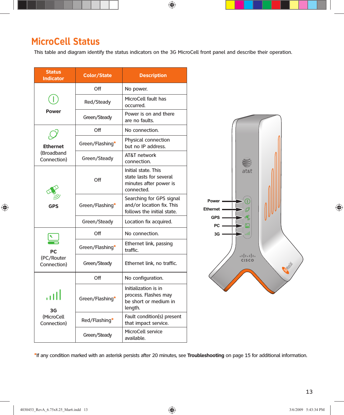
GemTek Technology 3GFP980217 DPH151-AT, FEMTOCELL, DUAL BAND, 2 PORT User Manual 4030453 RevA 6 75x8 25 Mar6 indd

Gemtek Technology Co., Ltd. DPH151-AT, FEMTOCELL, DUAL BAND, 2 PORT 4030453 RevA 6 75x8 25 Mar6 indd

Manual

UserManualAT&T3G MicroCell™4030453_RevA_6.75x8.25_Mar6.indd   14030453_RevA_6.75x8.25_Mar6.indd   1 3/6/2009   5:43:20 PM3/6/2009   5:43:20 PM
4030453_RevA_6.75x8.25_Mar6.indd   24030453_RevA_6.75x8.25_Mar6.indd   2 3/6/2009   5:43:24 PM3/6/2009   5:43:24 PM
3ContentsIMPORTANT SAFETY INSTRUCTIONS .....................................................................................................................4Welcome ......................................................................................................................................................................6Getting Started ..........................................................................................................................................................6  Before You Begin ............................................................................................................................................................................................................................................6 Unpack ..................................................................................................................................................................................................................................................................6Installation ..................................................................................................................................................................7Step 1. Ethernet Cabling ..........................................................................................................................................7  Option A: DSL/Cable Service with Router ......................................................................................................................................................................................7  Option B: DSL/Cable Service with Modem ....................................................................................................................................................................................8  Option C: DSL/Cable Service with Gateway ..................................................................................................................................................................................9  Option D: DSL/Cable Service with Router (Bridge Mode) ..................................................................................................................................................10Step 2. Startup ........................................................................................................................................................ 11Step 3. Account Activation ................................................................................................................................... 12MicroCell Status ...................................................................................................................................................... 13Operation ................................................................................................................................................................. 14 Performance Highlights ...........................................................................................................................................................................................................................14  What Happens When You Start Up the MicroCell?................................................................................................................................................................14  Authentication .........................................................................................................................................................................................................................................14  Location Fix ...............................................................................................................................................................................................................................................14    What If the GPS Status Indicator Continues to Flash After 20 Minutes? ...........................................................................................................14Troubleshooting ...................................................................................................................................................... 15 Hardware Problems....................................................................................................................................................................................................................................15 Service Problems .........................................................................................................................................................................................................................................16Antenna Descriptions ............................................................................................................................................ 17 Cellular Antenna ..........................................................................................................................................................................................................................................17 GPS Antenna ..................................................................................................................................................................................................................................................17  GPS Antenna Extension...........................................................................................................................................................................................................................17  GPS Antenna Extension Installation ................................................................................................................................................................................................17One-Year Limited Warranty .................................................................................................................................. 18Compliance Information ........................................................................................................................................ 19Radiation Exposure Statements .......................................................................................................................... 194030453_RevA_6.75x8.25_Mar6.indd   34030453_RevA_6.75x8.25_Mar6.indd   3 3/6/2009   5:43:24 PM3/6/2009   5:43:24 PM
4IMPORTANT SAFETY INSTRUCTIONS1)  Read these instructions.2)  Keep these instructions.3)  Heed all warnings.4)  Follow all instructions.5)  Do not use this apparatus near water.6)  Clean only with dry cloth.7)  Do not block any ventilation openings. Install in accordance with the manufacturer’s instructions.8)  Do not install near any heat sources such as radiators, heat registers, stoves, or other apparatus (including amplifiers) that produce heat.9)  Do not defeat the safety purpose of the polarized or grounding-type plug. A polarized plug has two blades with one wider than the other. A grounding-type plug has two blades and a third grounding prong. The wide blade or the third prong are provided for your safety. If the provided plug does not fit into your outlet, consult an electrician for replacement of the obsolete outlet.10)  Protect the power cord from being walked on or pinched particularly at plugs, convenience receptacles, and the point where they exit from the apparatus.11)  Only use attachments/accessories specified by the manufacturer.12)  Unplug this apparatus during lightning storms or when unused for long periods of time.20080814_Installer800Note to System InstallerCAUTION: To reduce the risk of electric shock, do notremove cover (or back). No user-serviceable parts inside. Refer servicing to qualified service personnel.WARNINGTO PREVENT FIRE OR ELECTRIC SHOCK, DO NOT EXPOSE THIS UNIT TO RAIN OR MOISTURE.For this apparatus, the cable shield/screen shall be grounded as close as practical to the point of entry of the cable into the building.For products sold in the US and Canada, this reminder is provided to call the system installer's attention to Article 800-93 and Article 800-100 of the NEC (or Canadian Electrical Code Part 1), which provides guidelines for proper grounding of the cable shield.This symbol is intended to alert you that uninsulated voltage within this product may have sufficient magnitude to cause electric shock.Therefore, it is dangerous to make any kind of contact with any inside part of this product.Ce symbole a pour but d’alerter toute personne qu’un contact avec une pièce interne de ce produit, sous tension et non isolée, pourrait être suffisant pour provoquer un choc électrique. Il est donc dangereux d’être en contact avec toute pièce interne de ce produit.This symbol is intended to alert you of the presence of important operating and maintenance (servicing) instructions in the literature accompanying this product.  Ce symbole a pour but de vous avertir qu’une documentation importante sur le fonctionnement et l’entretien accompagne ce produit.Notice to InstallersThe servicing instructions in this notice are for use by qualified service personnel only. To reduce the risk of electric shock, do not perform any servicing other than that contained in the operating instructions, unless you are qualified to do so.4030453_RevA_6.75x8.25_Mar6.indd   44030453_RevA_6.75x8.25_Mar6.indd   4 3/6/2009   5:43:25 PM3/6/2009   5:43:25 PM
5Power Source WarningA label on this product indicates the correct power source for this product. Operate this product only from an electrical outlet with the voltage and frequency indicated on the product label. If you are uncertain of the type of power supply to your home or business, consult your service provider or your local power company.The AC inlet on the unit must remain accessible and operable at all times.Ground the ProductWARNING: Avoid electric shock and fire hazard! If this product connects to cable wiring, be sure the cable system is grounded (earthed). Grounding provides some protection against voltage surges and built-up static charges.Protect the Product from LightningIn addition to disconnecting the AC power from the wall outlet, disconnect the signal inputs.Verify the Power Source from the On/Off Power LightWhen the on/off power light is not illuminated, the apparatus may still be connected to the power source. The light may go out when the apparatus is turned off, regardless of whether it is still plugged into an AC power source. Eliminate AC Mains OverloadsWARNING: Avoid electric shock and fire hazard! Do not overload AC mains, outlets, extension cords, or integral convenience receptacles. For products that require battery power or other power sources to operate them, refer to the operating instructions for those products.Provide Ventilation and Select a Location•  Remove all packaging material before applying power to the product. •  Do not place this apparatus on a bed, sofa, rug, or similar surface.•  Do not place this apparatus on an unstable surface.•  Do not install this apparatus in an enclosure, such as a bookcase or rack, unless the installation provides proper ventilation.•  Do not place entertainment devices (such as VCRs or DVDs), lamps, books, vases with liquids, or other objects on top of this product.•  Do not block ventilation openings.Protect from Exposure to Moisture and Foreign ObjectsWARNING: Avoid electric shock and fire hazard! Do not expose this product to dripping or splashing liquids, rain, or moisture. Objects filled with liquids, such as vases, should not be placed on this apparatus.WARNING: Avoid electric shock and fire hazard! Unplug this product before cleaning. Do not use a liquid cleaner or an aerosol cleaner. Do not use a magnetic/static cleaning device (dust remover) to clean this product.WARNING: Avoid electric shock and fire hazard! Never push objects through the openings in this product. Foreign objects can cause electrical shorts that can result in electric shock or fire. Service WarningsWARNING: Avoid electric shock! Do not open the cover of this product. Opening or removing the cover may expose you to dangerous voltages. If you open the cover, your warranty will be void. This product contains no user-serviceable parts.WARNING: This device has anti-tampering technology. Attempts to open the enclosure by unqualified personnel may render the device inoperable.Check Product SafetyUpon completion of any service or repairs to this product, the service technician must perform safety checks to determine that this product is in proper operating condition.Protect the Product When Moving ItAlways disconnect the power source when moving the apparatus or connecting or disconnecting cables. 20081017_3G_Micro_Cell_SafetyIMPORTANT SAFETY INSTRUCTIONS, continued4030453_RevA_6.75x8.25_Mar6.indd   54030453_RevA_6.75x8.25_Mar6.indd   5 3/6/2009   5:43:25 PM3/6/2009   5:43:25 PM
6WelcomeCongratulations on purchasing the AT&T 3G MicroCell™. The MicroCell provides voice and data service to AT&T 3G wireless phones and devices within a home or small business. The MicroCell is secure and delivers maximum cellular signal strength within its coverage area – it’s like having your own mini cell tower in your home or office. Getting Started Before You BeginTo operate the MicroCell, you must have the following items:•  Internet service over DSL or Cable*•  Modem or gateway (a router is optional)•  PC with Internet access to register your devicePlease verify these requirements before going any further.UnpackRemove the contents of the MicroCell package and verify that you received the following:If anything is missing or appears to be damaged, contact Customer Support at 800.331.0500 for assistance.* Downstream speeds of at least 1.5 Mbps and upstream speeds of at least 384 Kbps are recommended for best performance. There are no restrictions on    broadband service providers.AT&T 3GMicroCell™MicroCell3GUser Manual and Getting Started GuideUnpack Your AT&T 3G MicroCell™ Remove the contents of the AT&T 3G MicroCell™ package and verify that you received the following:If anything is missing or appears to be damaged, contact Customer Support at 800.331.0500 for assistance.Getting Started GuideAT&T 3G MicroCell™AT&T 3G MicroCell™MicroCell3GUserManualAT&T3G MicroCell™GPS AntennaExtension(Packaged Separately; Installation instructions provided in the AT&T 3G MicroCell™ User Manual)AC PowerAdapterYellowEthernet Cable4030453_RevA_6.75x8.25_Mar6.indd   64030453_RevA_6.75x8.25_Mar6.indd   6 3/6/2009   5:43:25 PM3/6/2009   5:43:25 PM
7InstallationThe MicroCell is a plug-and-play device that installs in around 20 minutes. Connecting the MicroCell to your pre-existing equipment is straight forward, but be sure to read the cabling instructions carefully before making connections.Note: Before starting, you can view AT&T’s online MicroCell demonstration at att.com/3GMicroCell.Step 1. Ethernet Cabling There are three commonly used Ethernet cabling options for installing your device and a fourth that is seldom used. Which one is right for you, depends on the equipment setup you have.•  Option A: DSL/Cable Service with Router – You have DSL/Cable service, a broadband modem, and a router that supports a PC network. See Ethernet cabling instructions on this page.•  Option B: DSL/Cable Service with Modem – You have DSL/Cable service and a broadband modem that supports a single PC. See page 8 for Ethernet cabling instructions.•  Option C: DSL/Cable Service with Gateway – You have DSL/Cable service and a broadband gateway that supports a PC network. See page 9 for Ethernet cabling instructions.•  Option D: DSL/Cable Service with Router (Bridge Mode) - You have DSL/Cable service, a broadband modem in bridge mode and a router with a PPPoE termination (this configuration is seldom used). See page 10 for Ethernet cabling instructions.Option A: DSL/Cable Service with RouterPlace the MicroCell upright, near the modem and router.1. Disconnect the Ethernet cable from the modem (see dotted line), while leaving the other end connected to the router.2. Reconnect the Ethernet cable to the black connector marked Computer on the MicroCell.3. Find the yellow Ethernet cable that came with the MicroCell and connect it between the yellow connector marked Ethernet on the MicroCell and the Ethernet port on the modem.4. Go to Step 2. Startup.Note: It is essential for the router to be connected to the PC port to ensure the best quality of service on the MicroCell.AntennaComputerEthernetPowerResetMicroCell3GAT&T 3GMicroCell™T14074RouterDSL/CableModemPCModemEthernet1234/UplinkLAN/WANPowerPowerResetCable/PhoneJack23net14030453_RevA_6.75x8.25_Mar6.indd   74030453_RevA_6.75x8.25_Mar6.indd   7 3/6/2009   5:43:31 PM3/6/2009   5:43:31 PM
8Option B: DSL/Cable Service with ModemPlace the MicroCell upright, near the modem.1. Disconnect the Ethernet cable from the modem (see dotted line), while leaving the other end connected to the PC.2. Reconnect the Ethernet cable to the black connector marked Computer on the MicroCell.3. Find the yellow Ethernet cable that came with the MicroCell and connect it between the yellow connector marked  Ethernet on the MicroCell and the Ethernet port on the modem.4. Go to Step 2. Startup.Note: It is essential for the PC to be connected to the PC port to ensure the best quality of service on the MicroCell. AntennaComputerEthernetPowerResetMicroCell3GAT&T 3GMicroCell™ModemEthernet PowerResetCable/PhoneJack3PCern21DSL/CableModemWhat if my PC and modem are connected through a USB cable?If you have previously used the USB interfaces on your modem and PC to connect the devices, there are two cabling alternatives you can try:•  Remove the USB cable and install Ethernet cables according to the illustration.*   OR•  Obtain USB-to-RJ45 adapters (not shown) and install one with the yellow Ethernet cable and the other with your   USB cable according to the illustration. *Requires a second Ethernet cable, not included.4030453_RevA_6.75x8.25_Mar6.indd   84030453_RevA_6.75x8.25_Mar6.indd   8 3/6/2009   5:43:32 PM3/6/2009   5:43:32 PM
9AntennaComputerEthernetPowerResetMicroCell3GAT&T 3GMicroCell™Cable/PhoneJackDSL/CableGateway1234LAN/WAN PowerPC1Option C: DSL/Cable Service with GatewayPlace the MicroCell upright, near the gateway.1. Find the yellow Ethernet cable that came with the MicroCell and connect it between the yellow connector marked Ethernet on the MicroCell and a free port on the gateway.2.  Go to Step 2. Startup.4030453_RevA_6.75x8.25_Mar6.indd   94030453_RevA_6.75x8.25_Mar6.indd   9 3/6/2009   5:43:32 PM3/6/2009   5:43:32 PM
10Option D: DSL/Cable Service with Router (Bridge Mode)Few households or small businesses have this type of setup. Do not set your MicroCell up this way unless you know that your modem has been configured in bridge mode with a PPPoE termination on the router.Place the MicroCell upright, near the modem and router.1. Find the yellow Ethernet cable that came with the MicroCell and connect it between the yellow connector marked Ethernet on the MicroCell and a free port on the router.2. Go to Step 2. Startup.AntennaComputerEthernetPowerResetMicroCell3GAT&T 3GMicroCell™T14077RouterDSL/CableModemPCModemEthernet1234/UplinkLAN/WANPowerPowerResetCable/PhoneJack14030453_RevA_6.75x8.25_Mar6.indd   104030453_RevA_6.75x8.25_Mar6.indd   10 3/6/2009   5:43:33 PM3/6/2009   5:43:33 PM
11Step 2. StartupNote: Make sure all Ethernet cabling is complete before performing this task.1.  Turn off power to your PC, router (if you have one), modem or gateway. Note: If equipped with a backup battery, it may be necessary to press “reset” on your modem or gateway. See the user documentation for your device.Make sure all of the devices are turned off before you go to the next step.2.  Wait a minute, then turn on the modem or gateway first, the router second (if you have one), and the PC last. Wait a few moments before turning on each device.3.  Find the AC adapter that came with your MicroCell and connect it as shown.4.  Verify the status of your devices.• Make sure that the Power status indicator on the front panel is steady green and that the Ethernet and PC status indicators are flashing or steady green.•  Make sure that the status indicators on your router (if you have one), modem or gateway are operating as they normally do (this may take a few minutes).5.  Open a browser on your PC and connect to the Internet.AntennaComputerEthernetPowerResetMicroCell3GAT&T 3GMicroCell™AC PowerAdapterPowerOutletT140783Go to the AT&T 3G MicroCell™ home page: att.com/3GMicroCell  If you can connect to the MicroCell home page, then you have performed the Ethernet Cabling and Startup tasks correctly. Congratulations! Go to Step 3. Account Activation.What if you can’t connect to the AT&T 3G MicroCell™ home page?If you are having trouble connecting to the Internet, confirm Step 1. Ethernet Cabling and Step 2. Startup. If that doesn’t help, refer to the Troubleshooting section on page 15.4030453_RevA_6.75x8.25_Mar6.indd   114030453_RevA_6.75x8.25_Mar6.indd   11 3/6/2009   5:43:33 PM3/6/2009   5:43:33 PM
12Step 3. Account Activation1. Go to att.com/3GMicroCell, select the ‘Personal Wireless’   link under “Set Up & Activate your MicroCell” and  login. Then follow the instructions on the website that are  required to register your device and activate your account.2. When service is available, every 3G device on your   Approved User List that is within range of the MicroCell will  display the 3G screen icon and AT&T MicroCell.* *Text and screen icon may vary with device manufacturer.    See the user documentation that came with your 3G   device.What if you can’t get your MicroCell to work?If the GPS status indicator continues to flash after 20 minutes, you may need the GPS antenna extension. A description of the device and installation instructions are on page 17.After registering your MicroCell, it can take up to 20 minutes to activate. Service is available when both the GPS and  3G status indicators on the MicroCell front panel turn to steady green (for a description of all status indicators, see MicroCell Status on page 13).If your handset displays  the 3G screen icon and AT&T MicroCell, account activation was successful. Congratulations! You can now make phone calls using your AT&T 3G MicroCell™ service.Device is registered and MicroCell service is availableThu, Jan 08 09:35 amAT&T MicroCellDevice is not registered and/or MicroCell service is not availableThu, Jan 08 09:35 amAT&TT14079MicroCell3GGPS StatusIndicator3G StatusIndicator4030453_RevA_6.75x8.25_Mar6.indd   124030453_RevA_6.75x8.25_Mar6.indd   12 3/6/2009   5:43:33 PM3/6/2009   5:43:33 PM
13MicroCell StatusThis table and diagram identify the status indicators on the 3G MicroCell front panel and describe their operation.MicroCell3GPowerEthernetGPSPC3GT14082Status Indicator Color/State DescriptionPowerOff No power.Red/Steady MicroCell fault has occurred.Green/Steady Power is on and there are no faults.Ethernet(Broadband Connection)Off No connection.Green/Flashing*Physical connection but no IP address.Green/Steady AT&T network connection.GPSOffInitial state. This state lasts for several minutes after power is connected.Green/Flashing*Searching for GPS signal and/or location fix. This follows the initial state.Green/Steady Location fix acquired.PC (PC/Router Connection)Off No connection.Green/Flashing*Ethernet link, passing traffic.Green/Steady Ethernet link, no traffic.3G(MicroCellConnection)Off No configuration.Green/Flashing*Initialization is in process. Flashes may be short or medium in length.Red/Flashing*Fault condition(s) present that impact service.Green/Steady MicroCell service available.*If any condition marked with an asterisk persists after 20 minutes, see Troubleshooting on page 15 for additional information.4030453_RevA_6.75x8.25_Mar6.indd   134030453_RevA_6.75x8.25_Mar6.indd   13 3/6/2009   5:43:34 PM3/6/2009   5:43:34 PM
14OperationPerformance HighlightsHere are some performance highlights for AT&T 3G MicroCell™ service using the MicroCell:•  Supports AT&T 3G wireless phones and devices•  Supports up to four simultaneous calls• Supports call transfer to the cellular network•  Supports UMTS bands 2 & 5 (1900 MHz and 850 MHz)•  Supports E911 Service*What Happens When You Start Up the MicroCell?AuthenticationAt startup, the MicroCell links to the AT&T network using your Internet service. The AT&T network then authenticates the MicroCell and its location, a process that can take up to 20 minutes to complete. AT&T 3G MicroCell™ service is withheld until the authentication process completes.Location FixThe authentication process cannot move forward without precise location data (referred to here as a location fix). The MicroCell acquires much of this data from a Global Positioning System (GPS) satellite.• For cold starts (first-time power-up), the MicroCell requires stronger satellite signals and acquisition will take longer. For warm starts (power-up within 20 minutes of a successful GPS fix), the MicroCell can get by with weaker satellite signals and acquisition should occur faster than for a cold start.•  At power-up, the GPS status indicator is off for several minutes, then flashes repeatedly while the MicroCell gathers location data.•  When the process completes, the GPS status indicator turns to steady green and authentication continues.•  The 3G status indicator flashes repeatedly during authentication, then turns to steady green when AT&T 3G MicroCell™ service is granted.What If the GPS Status Indicator Continues to Flash After 20 Minutes?If the GPS status indicator is still flashing after 20 minutes, your MicroCell has failed to acquire a location fix and is unlikely to succeed. The cause in most cases is low satellite signal strength at the current MicroCell location. See Troubleshooting on page 15 for steps you can take to improve satellite signal strength.*E911 ServiceThe MicroCell supports E911 (wireless 9-1-1 service) unless the device loses electrical power or Internet access. In the event of a service disruption, you won’t be able to use E911 service with your wireless device unless you have access to the AT&T wireless network. Additionally, if electrical power is lost for more than 20 minutes, it will be necessary for the MicroCell to re-authenticate, which will further delay resumption of E911 access. The same is true if you move your MicroCell to a new address.4030453_RevA_6.75x8.25_Mar6.indd   144030453_RevA_6.75x8.25_Mar6.indd   14 3/6/2009   5:43:34 PM3/6/2009   5:43:34 PM
15TroubleshootingYour AT&T 3G MicroCell™ has been engineered to provide continuous service without intervention on your part. Occasionally, though, hardware faults and broadband service interruptions can occur that disrupt the operation of the 3G MicroCell. For these occasions, there are remedial troubleshooting steps you can take to find the source of the problem and restore operation.Note: When you suspect any disruption of service, always look at the MicroCell front panel indicators to determine the operational status.Hardware ProblemsIf… Then…The Power statusindicator is off.The MicroCell is not getting AC power.•  Make sure the AC adapter is securely connected between the MicroCell power connector and AC outlet or power strip (see the power cabling diagram on page 11).•  Make sure there are no faults in the power strip or in the building’s power system.The Power statusindicator is red.A hardware fault on the MicroCell has occurred.•  Recycle power on the MicroCell (OFF/ON).•  If the Power status indicator stays red, contact Customer Support at 800.331.0500 for assistance.The GPS status indicator is flashing after 20 minutes.The MicroCell cannot acquire a location fix.• This condition usually occurs because the satellite signal is weak due to obstacles between the MicroCell and the open sky (window tinting, structures, trees, clouds, etc.) or because the MicroCell is too far from a window (see Location Fix on page 14 for more information).To fix:1. Disconnect power and Ethernet cabling.2. Move the MicroCell to a window with unobstructed access to the sky.3. Reconnect power and wait for a location fix, i.e., when the GPS status indicator turns to steady green. This could take up to 20 minutes.4. Move the unit back to its original position and complete Step 1. Ethernet Cabling, Step 2. Startup, and Step 3. Account Activation.Note: You must re-connect power within 20 minutes or the MicroCell will lose the location data and the entire procedure will need to be repeated. • An alternative solution is to install the GPS antenna extension (see Antenna Descriptions on page 17 for more information and installation instructions).The Ethernet statusindicator is off.There is no physical connection to the MicroCell Ethernet port.•  Make sure an Ethernet cable is securely connected as required for the Ethernet Cabling option you chose.The PC status indicator is off.There is no physical connection to the MicroCell Computer port.•  Make sure an Ethernet cable is securely connected as required for the Ethernet Cabling option you chose.4030453_RevA_6.75x8.25_Mar6.indd   154030453_RevA_6.75x8.25_Mar6.indd   15 3/6/2009   5:43:34 PM3/6/2009   5:43:34 PM
16If… Then…The 3G status indicator is off.There is no configuration. •  To fix, recycle power on the MicroCell.•  If the condition does not clear, contact Customer Support at 800.331.0500 for assistance.The 3G status indicator isgreen/flashing.Initialization is in process.•  If you haven’t completed online registration and account activation, do so now (see Step 3. Account Activation on page 12).Note: Registration and account activation should be completed in a single uninterrupted session, if possible. If the process is interrupted and/or takes an hour or more to complete, it is recommended that you recycle power on the MicroCell to restart initialization and authentication.•  Assuming you have completed the online requirements in a timely fashion, the 3G status indicator should turn to steady green within minutes of achieving a location fix (see the GPS status indicator). If you don’t have a location fix, troubleshoot that condition first.•  If these measures fail, contact Customer Support at 800.331.0500 for assistance.The 3G status indicator is red/flashing.Faults are present on the MicroCell that impact service.•  Check the GPS status indicator. If it is solid green while the 3G status indicator is flashing red, most likely the problem is that a location fix was obtained, but the location is outside the tolerance allowed by AT&T.•  Contact Customer Support at 800.331.0500 for assistance.Service ProblemsIf… Then…The PC network performance declines.Traffic across the MicroCell has risen to a critical level.•  Check for unusually heavy data requests (video downloads are likely suspects) and limit them, if possible.•  If the decline is chronic, consider upgrading service.A 3G device is unable to access the AT&T 3G MicroCell™ service.The device may not be registered (see Step 3. Account Activation on page 12).Approved callers are having trouble accessing your AT&T 3G MicroCell™ service.The MicroCell may be serving a full load of calls.Note: A full load is four simultaneous calls.Hardware Problems, continued4030453_RevA_6.75x8.25_Mar6.indd   164030453_RevA_6.75x8.25_Mar6.indd   16 3/6/2009   5:43:34 PM3/6/2009   5:43:34 PM
17Antenna DescriptionsThe MicroCell has one antenna for cellular signals and another for GPS signals. If GPS signal strength is too low, a port for connecting the GPS antenna extension is also available.Cellular AntennaThe cellular antenna is mounted inside the MicroCell enclosure and is for transceiving cellular traffic with registered 3G devices. The maximum range of the MicroCell is approximately 5000 square feet. Actual range will vary depending on the density of obstructions in the vicinity.GPS AntennaThe GPS antenna is mounted inside the MicroCell enclosure and is for receiving GPS signals. It cannot be adjusted, but has enough gain in most instances to detect signals in any room with a window.If the MicroCell cannot acquire a location fix (indicated by a flashing GPS status indicator), see Troubleshooting on page 15. Another option is to install the GPS antenna extension (see below). GPS Antenna ExtensionThe GPS antenna extension is a lengthy cable with a GPS antenna element on one end. This device is useful when there is no practical way to move the MicroCell close to a window.GPS Antenna Extension Installation•  Plug one end of the GPS antenna extension connector to the round connector marked Antenna on the MicroCell and place the other end as close as possible to the nearest window with unobstructed access to the sky. •  Recycle power on the MicroCell. •  If the extension is successful, the GPS status indicator will turn to steady green, which can take up to 20 minutes. You must then allow authentication to continue until the 3G status indicator turns to steady green.•  Leave the GPS antenna extension installed, if possible. If not, then disconnect the device and store it nearby; it may be necessary to reinstall the GPS antenna extender if the MicroCell has to reacquire the location fix.If this procedure fails, contact Customer Support at 800.331.0500 for assistance.AntennaComputerEthernetPowerResetMicroCell3GAT&T 3GMicroCell™T14083GPS AntennaExtensionResetButtonPressing the Reset button restores the MicroCell to its factory default settings. Do not press this button unless you have been asked to by Customer Support.4030453_RevA_6.75x8.25_Mar6.indd   174030453_RevA_6.75x8.25_Mar6.indd   17 3/6/2009   5:43:35 PM3/6/2009   5:43:35 PM
18One-Year Limited WarrantyAT&T warrants to the first retail purchaser of this 3G MicroCell device that should this product or any part be proved defective in materials or workmanship, from date of purchase, as evidenced by a register receipt or other valid proof of purchase for a period of one (1) year, then it will be subject to the terms of this one-year limited warranty. Such defects will be repaired or replaced without charge for parts or labor directly related to the defect. Limitations and Exclusions: This warranty does not apply to any cost incurred for removal or reinstallation, or to any product or part thereof which has suffered through normal wear and tear, alteration, improper installation, physical abuse, misuse, neglect or accident. Nor does it cover defects caused by shipment to an AT&T service center, or repair or service of the product by anyone other than an AT&T service center. Damage resulting from an act of God, including but not limited to fire, flood, earthquake and other natural disasters will be excluded. This limited warranty is in lieu of all other warranties, express or implied either in fact or by operations of law, statutory or otherwise, including, but not limited to, any implied warranty of merchantability or fitness for a particular use. AT&T does not authorize any other person to assume any liability beyond the warranty herein described. In no event, whether based in contract, tort or any other legal theory, shall AT&T or any of its agents or sellers be liable for incidental, consequential, indirect, special, or punitive damages of any kind resulting from the use of this product, including but not limited to interrupted or incomplete phone calls, omission or negligence arising out of any breach of this warranty. In no event shall AT&T or its agents or sellers be liable for any damages however defined in an amount in excess of the purchase price.4030453_RevA_6.75x8.25_Mar6.indd   184030453_RevA_6.75x8.25_Mar6.indd   18 3/6/2009   5:43:35 PM3/6/2009   5:43:35 PM
19FCC ComplianceUnited States FCC ComplianceThis device has been tested and found to comply with the limits for a Class B digital device, pursuant to part 15 of the FCC Rules. These limits are designed to provide reasonable protection against such interference in a residential installation. This equipment generates, uses, and can radiate radio frequency energy. If not installed and used in accordance with the instructions, it may cause harmful interference to radio communications. However, there is no guarantee that interference will not occur in a particular installation. If this equipment does cause harmful interference to radio or television reception, which can be determined by turning the equipment OFF and ON, the user is encouraged to try to correct the interference by one or more of the following measures:•  Reorient or relocate the receiving antenna, if applicable.•  Increase the separation between the equipment and receiver.•  Connect the equipment into an outlet on a circuit different from that to which the receiver is connected.•  Consult the service provider or an experienced radio/television technician for help.Any changes or modifications not expressly approved by Cisco Systems, Inc., could void the user’s authority to operate the equipment.The information shown in the FCC Declaration of Conformity paragraph below is a requirement of the FCC and is intended to supply you with information regarding the FCC approval of this device. The phone numbers listed are for FCC-related questions only and not intended for questions regarding the connection or operation for this device. Please contact your service provider for any questions you may have regarding the operation or installation of this device. Declaration of ConformityThis device complies with Part 15 of FCC Rules. Operation is subject to the following two conditions: 1) the device may not cause harmful interference, and 2) the device must accept any interference received, including interference that may cause undesired operation.AT&T 3G MicroCell™Model: MicroCellManufactured by: Cisco Systems, Inc. 5030 Sugarloaf Parkway Lawrenceville, Georgia 30044 USATelephone: 770-236-1077Canada EMI RegulationThis Class B digital apparatus complies with Canadian ICES-003.Cet appareil numérique de la class B est conforme à la norme NMB-003 du Canada.This device complies with RSS-132 and RSS-133 of the Industry Canada Rules. Operation is subject to the following two conditions:•  This device may not cause harmful interference.•  This device must accept any interference received, including interference that may cause undesired operation.20060628 FCC StandardSoftware and Firmware UseThe software described in this document is protected by copyright law and furnished to you under a license agreement. You may only use or copy this software in accordance with the terms of your license agreement.The firmware in this equipment is protected by copyright law. You may only use the firmware in the equipment in which it is provided. Any reproduction or distribution of this firmware, or any portion of it, without our express written consent is prohibited.DisclaimerCisco Systems, Inc. assumes no responsibility for errors or omissions that may appear in this guide. We reserve the right to change this guide at any time without notice.Radiation Exposure StatementsNote: This transmitter must not be collocated or operated in conjunction with any other antenna or transmitter. This equipment should be installed and operated with a minimum distance of 7.9 inches (20 cm) between the radiator and your body.United StatesThis equipment complies with FCC radiation exposure limits set forth for an uncontrolled environment. This system has been evaluated for RF exposure for humans in reference to ANSI C 95.1 (American National Standards Institute) limits. The evaluation was based on evaluation per ANI C 95.1 and FCC OET Bulletin 65C rev 01.01. The minimum separation distance from the antenna/radiator to a general bystander is 7.9 inches (20 cm) to maintain compliance.This transmitter must not be collocated or operating in conjunction with any other antenna or transmitter.The availability of some specific channels and/or operational frequency bands are country dependent and are firmware programmed at the factory to match the intended destination. The firmware setting is not accessible by the end user.CanadaThis equipment complies with IC radiation exposure limits set forth for an uncontrolled environment. This system has been evaluated for RF exposure for humans in reference to ANSI C 95.1 limits. The evaluation was based on evaluation per RSS-102 Rev 2. The minimum separation distance from the antenna to general bystander is 7.9 inches (20 cm) to maintain compliance.4030453_RevA_6.75x8.25_Mar6.indd   194030453_RevA_6.75x8.25_Mar6.indd   19 3/6/2009   5:43:35 PM3/6/2009   5:43:35 PM
Cisco, Cisco Systems, the Cisco logo, the Cisco Systems logo, and Scientific Atlanta are registered trademarks or trademarks of Cisco Systems, Inc. and/or its affiliates in the United States and certain other countries.AT&T, the AT&T logo, and AT&T 3G MicroCell are trademarks of AT&T Intellectual Property.All other trademarks mentioned in this document are the property of their respective owners.Product and service availability is subject to change without notice.© 2009 Cisco Systems, Inc. All rights reserved.March 2009     Part Number 4030453 Rev A Cisco Systems, Inc. 678.277.1000  5030 Sugarloaf Parkway, Box 465447  Lawrenceville, GA 30042  www.scientificatlanta.com4030453_RevA_6.75x8.25_Mar6.indd   204030453_RevA_6.75x8.25_Mar6.indd   20 3/6/2009   5:43:35 PM3/6/2009   5:43:35 PM

Navigation menu