GemTek Technology AP930301G 54Mb Operator Access Point User Manual Title
Gemtek Technology Co., Ltd. 54Mb Operator Access Point Title
UserManual.wiki
>
GemTek Technology
>
AP930301G User Manual
>
User Manual
Contents
1.
User Manual
2.
Manual
User Manual
Navigation menu
Upload a User Manual
Namespaces
Wiki Guide
HTML
PDF
Info
Views
User Manual
Discussion / Help
Navigation

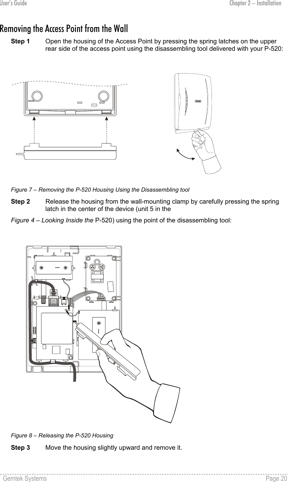
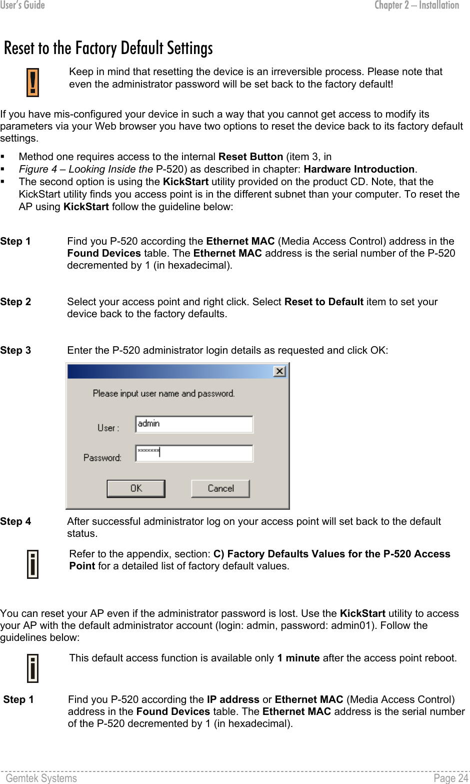
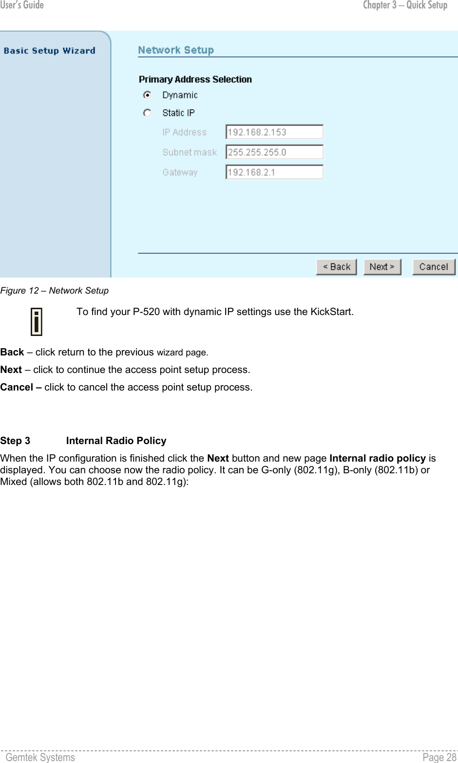
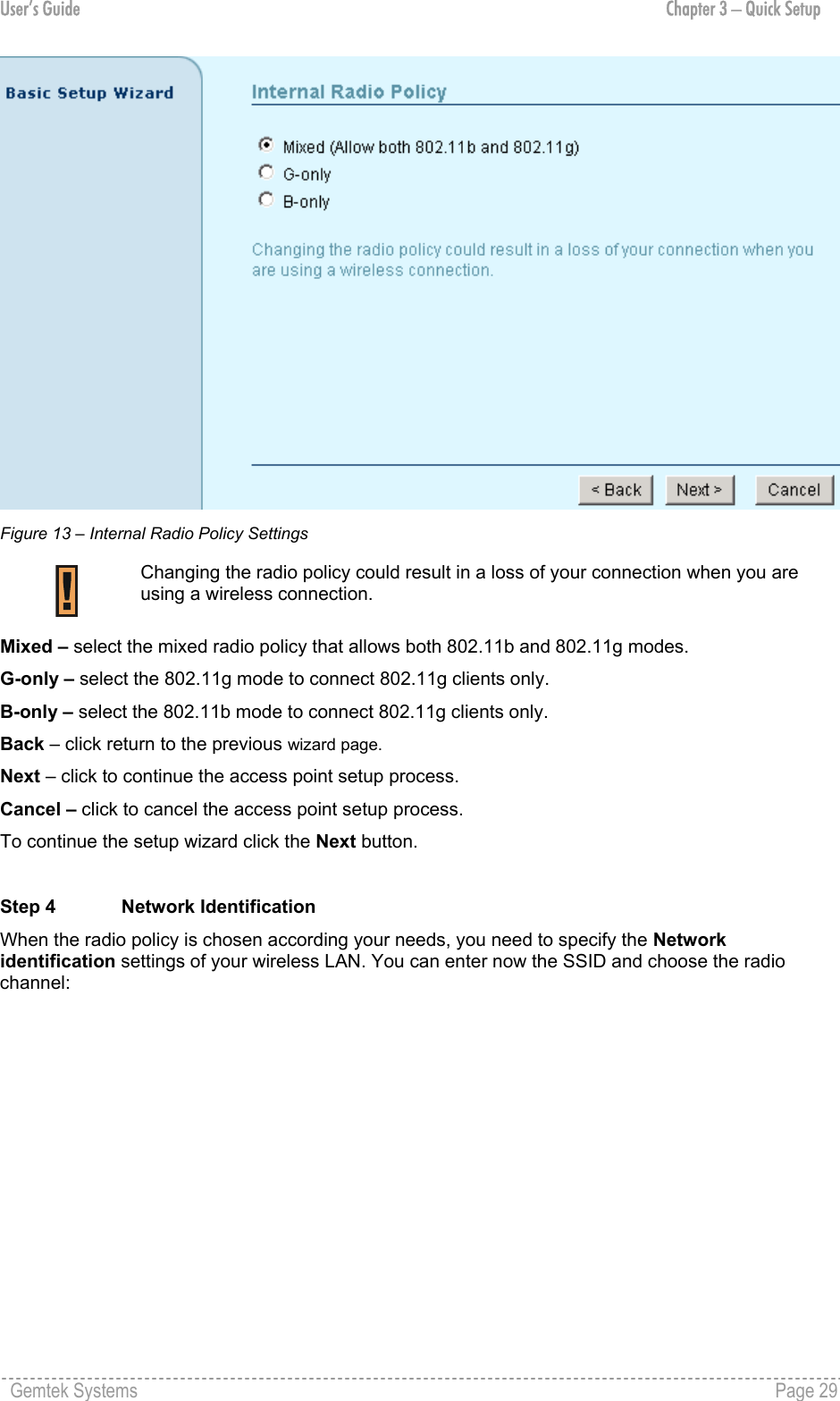
![User’s Guide Chapter 3 – Quick Setup Cancel – click to cancel the access point setup process. To continue the setup wizard click the Next button and choose the primary address selection. Step 2 Network Setup The IP configuration as described below is required for device management purposes. IP addresses can either be retrieved from a DHCP server or configured manually. To setup the device IP configuration manually, choose the Static IP radio button and enter the credentials: Figure 11 – Network Setup Settings IP Address – specify the access point’s IP address [digit and dots]. When shipped from the factory or reset to factory settings, the AP defaults to a static IP address of 192.168.2.2. Subnet Mask – specify the access point’s subnet mask [digit and dots]. When shipped from the factory or reset to factory settings, the AP defaults to a subnet mask of 255.255.255.0. Gateway – specify the IP address of the access point’s gateway [digit and dots]. When shipped from the factory or reset to factory settings, the AP defaults to a gateway IP address of 192.168.2.1. Select Dynamic radio button, if need that IP address should be assigned by the DHCP server. The static IP settings are displayed but have no affect on the network configuration: Gemtek Systems Page 27](https://usermanual.wiki/GemTek-Technology/AP930301G.User-Manual/User-Guide-415577-Page-27.png)
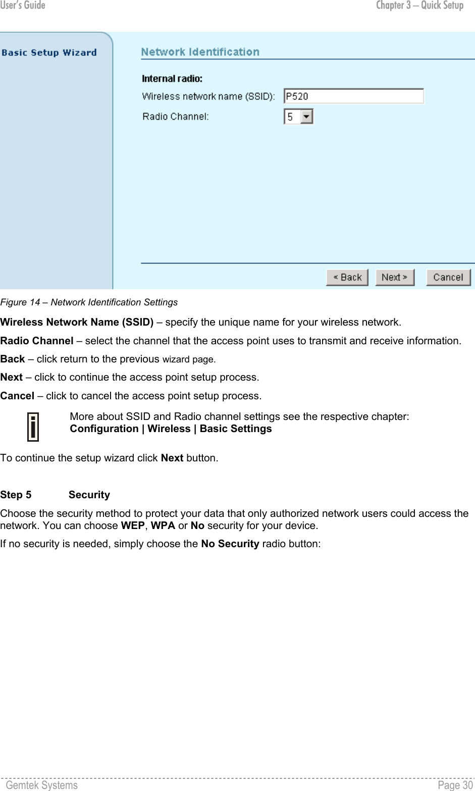
![User’s Guide Chapter 3 – Quick Setup Figure 15 – Security Settings Back – click return to the previous wizard page. Next – click to continue the access point setup process. Cancel – click to cancel the access point setup process. If you ant to choose WEP encryption, just select the Wired Equivalent Privacy (WEP) radio button and click Next button to configure the WEP encryption settings. You can then choose the encryption key length: Figure 16 – WEP Encryption Settings Key Length – choose the shared secret’s Key length from drop-down list [64-bits (10 characters)/ 128-bits (26 characters)]. Network Key – specify the shared secret. 5 colon-separated HEX (0-9, A-F, and a-f) pairs (e.g. 00:AC:01:35:FF) for the 64-bits WEP encryption; 13 colon-separated HEX (0-9, A-F, and a-f) pairs (e.g. 00:11:22:33:44:55:66:77:88:99:AA:BB:CC) for the 128-bits WEP encryption. Gemtek Systems Page 31](https://usermanual.wiki/GemTek-Technology/AP930301G.User-Manual/User-Guide-415577-Page-31.png)
![User’s Guide Chapter 3 – Quick Setup Back – click return to the previous wizard page. Next – click to continue the access point setup process. Cancel – click to cancel the access point setup process. To continue the setup wizard click the Next button and the new Administrator Password Setup page will appear. More about WEP settings see the respective chapter: Configuration | Security | Wireless Security | Wired Equivalent Privacy (WEP) If you want to choose WPA encryption, just select the Wi-Fi Protected Access (WPA) radio button in the Security page and click the Next button to configure the WPA encryption settings. You can now specify the WPA password phrase: Figure 17 – Wi-Fi Protected Access (WPA) Settings Pre-shared Key – specify WPA pre-shared key [8-63 characters]. Re-enter Pre-shared Key – re-enter the WPA pre-shared key to verify its accuracy [8-63 character]. Back – click return to the previous wizard page. Next – click to continue the access point setup process. Cancel – click to cancel the access point setup process. To configure WPA without pre-shared key but with dynamic key exchange via RADIUS refer to the chapter Configuration | Security | Wireless Security | Wi-Fi Protected Access (WPA) Step 6 Administrator Password Setup After the security settings have been configured successfully click the Next button and the final step Administrator Password Setup will be displayed. Here you can choose and modify the administrator password to protect your AP from unauthorized configuration. If you want to protect your access point from unauthorized access and configuration, select the Use password protection checkbox and specify a password: Gemtek Systems Page 32](https://usermanual.wiki/GemTek-Technology/AP930301G.User-Manual/User-Guide-415577-Page-32.png)
![User’s Guide Chapter 3 – Quick Setup Figure 18 – Administrator Password Setup Settings Password – enter the new password value used for user authentication in the system [4-32 symbols]. Confirm Password – re-enter the new password to verify its accuracy. Back – click to return to the main wizard page. Next – click to continue the access point setup process. Cancel – click to cancel the access point setup process. Step 7 Confirm Settings When Administrator’s password configuration is finished, click the Next button to finish the Setup Wizard. You just need to confirm that settings are correct: Figure 19 – Confirm Settings Gemtek Systems Page 33](https://usermanual.wiki/GemTek-Technology/AP930301G.User-Manual/User-Guide-415577-Page-33.png)
![User’s Guide Chapter 4 – Reference Manual Configuration Configuration | Configuration | Settings Summary The Settings Summary page shows important information of the P-520: its IP address, SSID, wireless security settings and access control status. The page is not configurable but displays the current system configuration only. Figure 21 – Settings Summary SSID – indicates the unique name for your wireless network. IP Address – indicates the IP address of your P-520. If two addresses are displayed this means that the access point retrieved its IP address dynamically via DHCP. The first IP address is the IGMP IP multicast address; the second IP is given from DHCP server’s pool. Wireless Security – indicates if security methods are enabled on your access point [None, WEP, WPA, 802.1X]. Access Control – indicates access control status [Any client/Selected clients only]. Configuration | Configuration | Identity The identity data of the access point are displayed here. You can use the first three fields Name, Location, Contact to describe the access point. These fields do not influence the behavior of the access point. But are for information purposes only. Gemtek Systems Page 37](https://usermanual.wiki/GemTek-Technology/AP930301G.User-Manual/User-Guide-415577-Page-37.png)
![User’s Guide Chapter 4 – Reference Manual Figure 22 – Identity Settings Name – specify the administrative name of the access point [string]. Location – specify the location where your device is installed [string]. Contact – specify the name of the person/company responsible for the P-520 [string]. MAC Address – displays the MAC address of the access point. Cannot be changed. Access Point Type – displays information on your type of access point. Cannot be changed. Firmware Version – displays the version number of the software that controls the access point. Boot Loader Version – displays the boot loader version. Cancel – restore all previous values. Apply – save changed configuration. Configuration | Local Area Network | Network Setup The IP configuration as described below is required for device management purposes. IP addresses can either be retrieved from a DHCP server or configured manually. Figure 23 – Network Setup Settings Gemtek Systems Page 38](https://usermanual.wiki/GemTek-Technology/AP930301G.User-Manual/User-Guide-415577-Page-38.png)
![User’s Guide Chapter 4 – Reference Manual IP Address – specify the access point’s IP address [digit and dots]. When shipped from the factory or reset to factory settings, the AP defaults to a static IP address of 192.168.2.2. Subnet Mask – specify the access point’s subnet mask [digit and dots]. When shipped from the factory or reset to factory settings, the AP defaults to a subnet mask of 255.255.255.0. Gateway – specify the IP address of the access point’s gateway [digit and dots]. When shipped from the factory or reset to factory settings, the AP defaults to a gateway IP address of 192.168.2.1. If you change the IP address manually, make sure that the chosen IP address is unused and belongs to the same IP subnet as your wired LAN, otherwise you will loose the connection to the P-520 from your current PC. If you enable the DHCP client via a Web browser, the browser will loose the connection after rebooting, because the IP address assigned by the DHCP server is not predictable. If Dynamic is selected the static IP settings are displayed but have no affect on the network configuration. The dynamic IP address and gateway address as assigned by the DHCP server are applied to the system after restart. To find your P-520 with dynamic IP settings use a utility such as Gemtek Systems KickStart. Configuration | Local Area Network | Virtual LAN A Virtual Local Area Network (VLAN) is a mechanism to segregate devices or groups of devices on the same physical LAN. P-520 allows the definition of a VLAN by a VLAN identifier. If you enable the VLAN functionality in the menu Configuration | Local Area Network | Virtual LAN all traffic from the wireless LAN to the LAN will be tagged with the specified VLAN ID. Incoming traffic from the wired LAN not tagged with the appropriate VLAN ID is discarded by the AP. Figure 24 – Virtual Local Area Network (VLAN) Settings To define a VLAN membership on the access point, select the checkbox and enter the VLAN identifier: Figure 25 – Enable Virtual Local Area Network (VLAN) VLAN id – specify the ID for your VLAN network [1 to 4094]. Wireless client devices connected to the AP are grouped into this VLAN. Cancel – restore all previous values. Gemtek Systems Page 39](https://usermanual.wiki/GemTek-Technology/AP930301G.User-Manual/User-Guide-415577-Page-39.png)
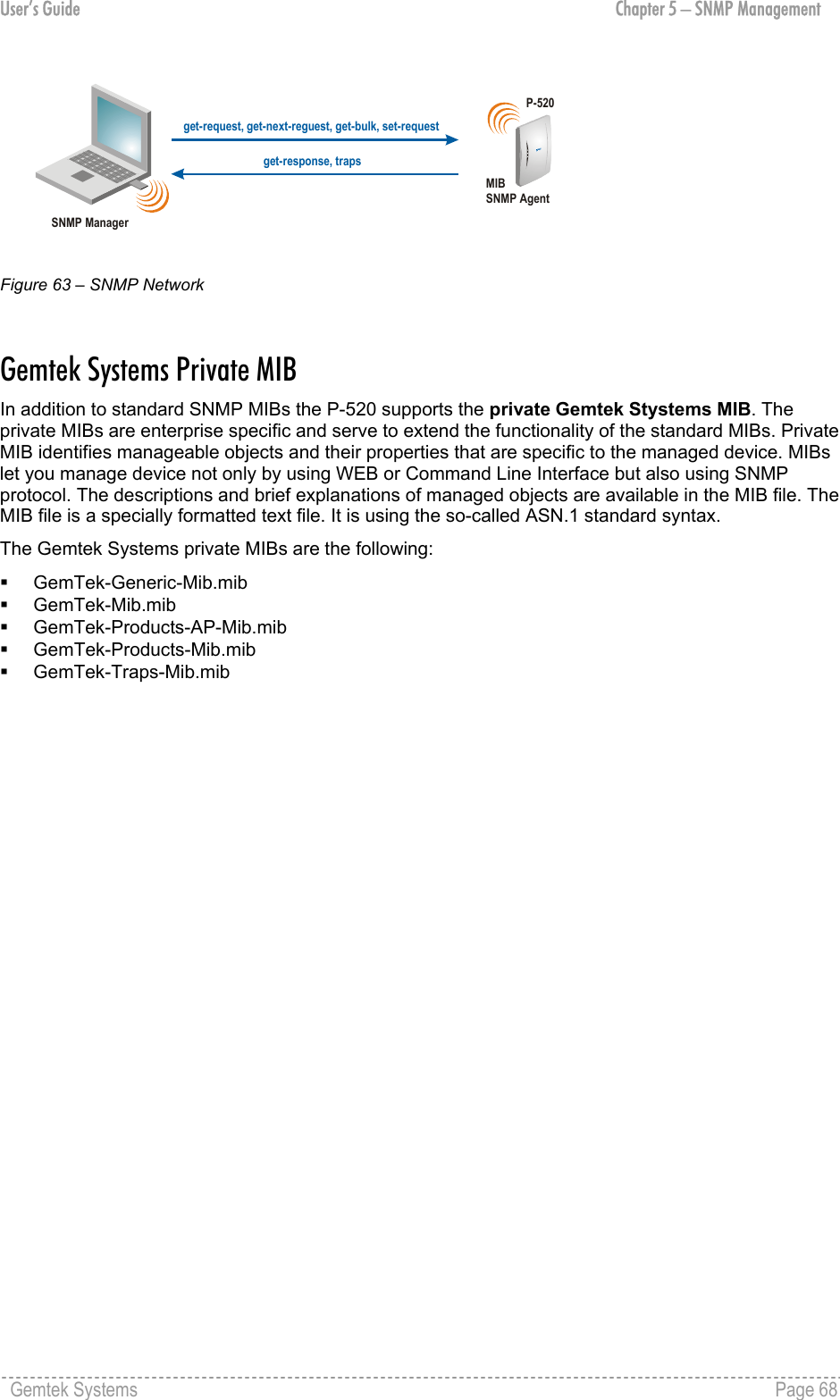
![User’s Guide Chapter 4 – Reference Manual Apply – save changed configuration. When VLAN is enabled you can view this interface statistic in Status | Interface Statistics page. There you can see such parameters as interface status, InOctets, InUcast, InMcast, OutOctets, OutUcast and OutMcast. Configuration | Wireless | Basic Settings Use the Configuration | Wireless | Basic Settings menu to configure the most relevant wireless settings of your access point. Figure 26 – Basic Wireless Settings Country – click on the select country… link and choose from drop-down list the country in which you will use the AP. According to the country chosen the regulatory domain settings change. You are not allowed to select radio channels and RF output power values other the permitted values for your country and regulatory domain. See also appendix B) Regulatory Domain/Channels. Regulatory Domain – displays the regulatory domain according selected country [ETSI/FCC]. Not configurable. IAPP – select this checkbox to enable seamless roaming of client stations between P-520 APs. By using the Inter-Access Point Protocol (IAPP) roaming, a client can be hand-over between access points when changing its physical location. The IAPP protocol is used to ensure all relevant session information is delivered to the new AP to which the client is moving. IAPP roaming is compatible with other Gemtek Systems products. Look at the scheme for more details about IAPP roaming: Gemtek Systems Page 40](https://usermanual.wiki/GemTek-Technology/AP930301G.User-Manual/User-Guide-415577-Page-40.png)
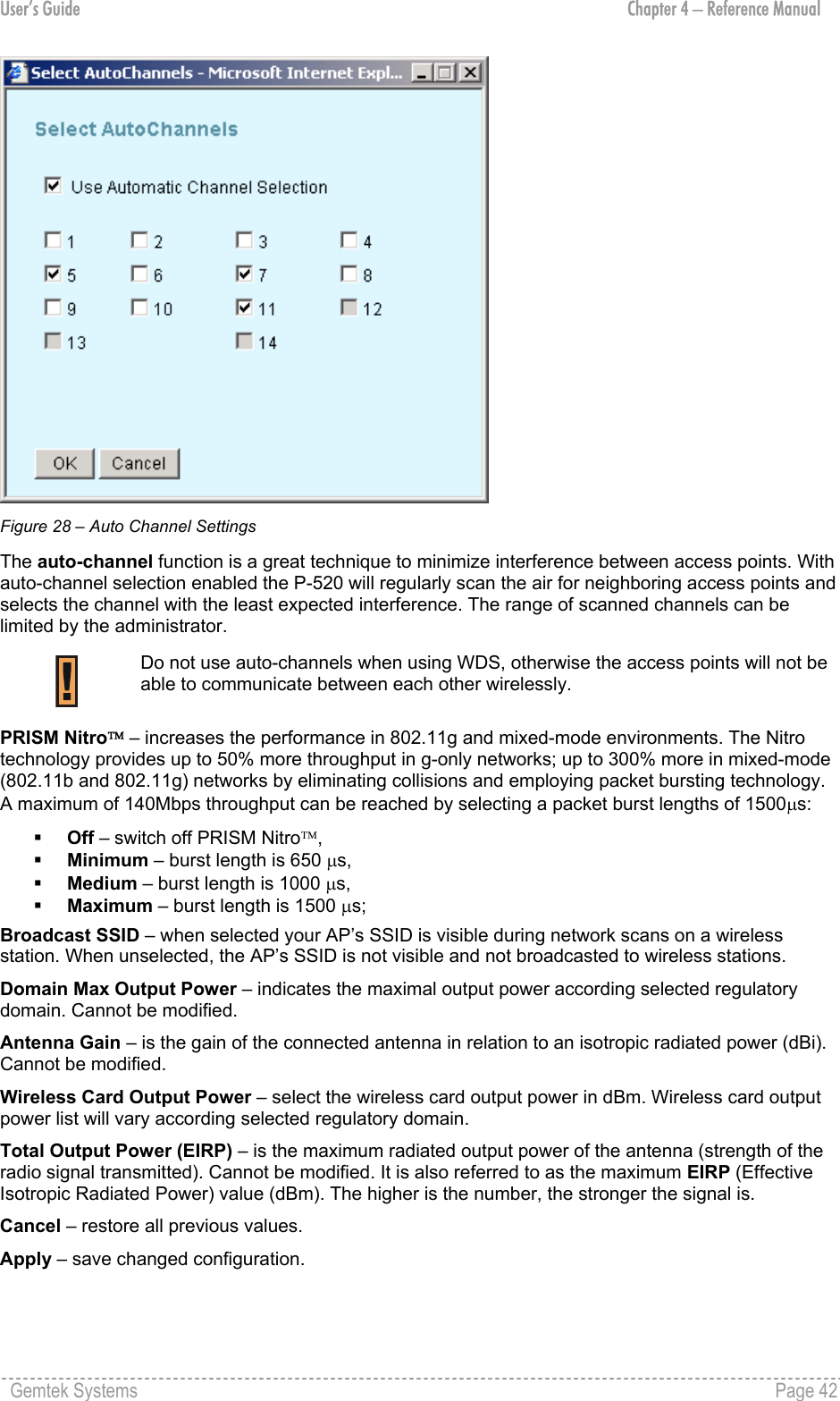
![User’s Guide Chapter 4 – Reference Manual IAPP RoamingAP1AP2ClientRADIUS Server Figure 27 – IAPP Roaming Scheme The wireless client is switched from AP1 to AP2 when entering the coverage area of the new access point (AP2). The roaming is performed without client re-authentication. The IAPP protocol ensures to inform the old AP1 of the new client association. The AP1 then stops the client RADIUS session, and the AP2 starts the client’s session with the RADIUS. IAPP roaming requires that all access points share the same SSID. Wireless Network Name (SSID) – is a unique name for your wireless network [1-32 symbols]. The default SSID is "P520" but you should change this to a personal wireless network name. The SSID is important for client stations when connecting to the access point. All client stations must have their client SSID settings configured and must use the same SSID. Band – click on the change policy… link and choose the policy of internal radio mode [Mixed/G-only/B-only]. Changing the radio policy could result in a loss of your connection when you are using a wireless connection. Radio Channel – select the channel that the access point uses to transmit and receive information. Multiple frequency channels are used to avoid interference between nearby access points. If you wish to operate more than one access point in overlapping coverage areas, we recommend a distance of at least four channels between the chosen channels. For example, for three access points in close proximity choose channels 1, 6 and 11. Before changing radio settings manually, verify that these settings comply with your national regulations. At all times, it is the responsibility of the end-user to ensure that the installation complies with local radio regulations. Refer to the appendix, B) Regulatory Domain/Channels for more details. Click on the autochannel… link and a pop-up window with auto channel settings will appear. You can now select a list of preferred channels: Gemtek Systems Page 41](https://usermanual.wiki/GemTek-Technology/AP930301G.User-Manual/User-Guide-415577-Page-41.png)
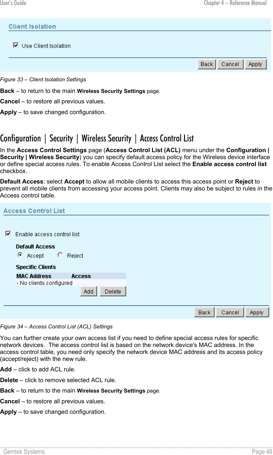
![User’s Guide Chapter 4 – Reference Manual Configuration | Wireless | Advanced Settings For normal operation the following default settings do not need to be modified. Changing the P-520 advanced settings requires expert knowledge of the 802.11 protocol and the radio functionality. The configuration menu Configuration | Wireless | Advanced Settings allows administrators to change low level radio parameters: Figure 32 – Advanced Wireless Settings Operational Rate Set – this setting specifies the set of Supported and Basic data rates at which the station may transmit data. Each rate shall be within the range from 2 to 127, corresponding to data rates in increments of 500 kb/s from 1 Mb/s to 63.5 Mb/s, and shall be supported for receiving data. This value is reported in transmitted Beacon, Probe Request, Probe Response, Association Request, Association Response, Reassociation Request, and Reassociation Response frames, and is used to determine whether a BSS with which the station desires to synchronize is suitable. Operational rate set is defined as hexadecimal string where highest bit of each digit represents if Supported rate is the Basic rate (basic rate = supported rate | 0x80, where “|” means “bitwise or” operation). Beacon Period – this setting specifies the amount of time between beacons in milliseconds. A beacon is a packet broadcast by the access point to synchronize the wireless network. RTS Threshold – this setting specifies the maximum packet size beyond which the Wireless LAN Card invokes its RTS/CTS mechanism. Packets that exceed the specified RTS threshold trigger the RTS/CTS mechanism. The NIC transmits packets smaller than this threshold without using RTS/CTS [[0-2347] default: 2347 (2347 means that RTS is disabled)]. Fragmentation Threshold – the fragmentation threshold, specified in bytes, determines whether packets will be fragmented and at what size. On an 802.11 wireless LAN, packets exceeding the fragmentation threshold are fragmented, i.e., split into, smaller units suitable for the circuit size. Packets smaller than the specified fragmentation threshold value are not fragmented [[256-2346] default: 2346 (2346 means that fragmentation is disabled)]. Cancel – to restore all previous values. Apply – to save changed configuration. Configuration | Security | Wireless Security | Client Isolation Use the Configuration | Security | Wireless Security| Client Isolation menu to configure the layer 2 user isolation feature. Select the Use Client Isolation checkbox to enable Layer 2 wireless client separation. In this case connected wireless stations are not able to communicate with each other. The client stations are isolated on MAC address level. Gemtek Systems Page 47](https://usermanual.wiki/GemTek-Technology/AP930301G.User-Manual/User-Guide-415577-Page-47.png)
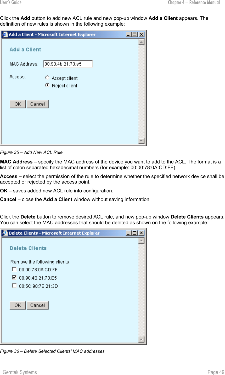
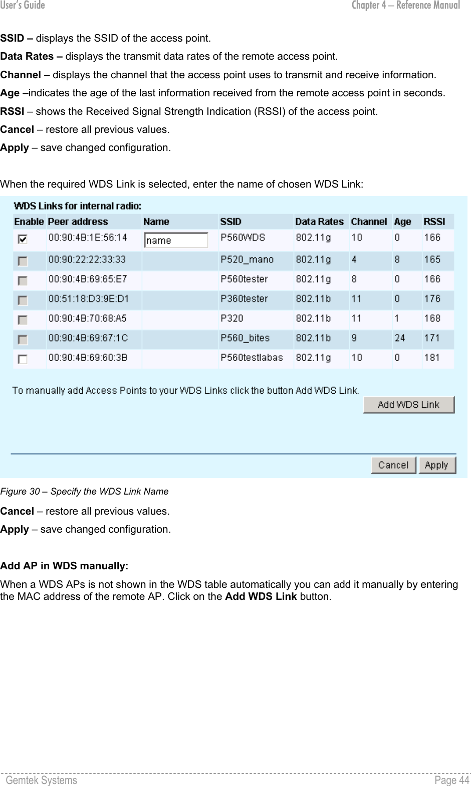
![User’s Guide Chapter 4 – Reference Manual OK – removes selected ACL rule from the list. Cancel – close the Delete Clients window without saving information. Configuration | Security | Wireless Security | RADIUS Servers Only 2 RADIUS servers can be configured on the system: one Authentication and one Accounting. RADIUS is an authentication, authorization and accounting (AAA) system. RADIUS enables operators to maintain a very large database of users. By using RADIUS, operators can implement policy-based management of their subscriber base. RADIUS further enables the collection of usage data (e.g. amount of time, amount of transferred bytes, and session time) for accounting purposes. Use the Configuration | Security | Wireless Security| RADIUS Servers menu to configure the RADIUS servers’ list and settings. By default there is no RADIUS server on the system: Figure 37 – RADIUS Servers' Settings Re-authentication Time – specify the number of seconds after which the access point re-authenticates client stations [0-2147483647]. The default value is 3600 seconds. If 0 is entered it means that stations will not have to re-authenticate as long as they are connected. IP address – displays RADIUS server’s IP address. Port Number – displays RADIUS server’s port number. Type – displays RADIUS server’s type. Add – click to add RADIUS server. Delete – click to remove selected RADIUS server. Back – to return to the main Wireless Security Settings page. Cancel – to restore all previous values. Apply – to save changed configuration. In the default configuration no RADIUS servers are define on the system. Click the Add button to add new RADIUS server and new pop-up window Add RADIUS server appears. You can define the RADIUS server’s parameters as shown on the following example: Gemtek Systems Page 50](https://usermanual.wiki/GemTek-Technology/AP930301G.User-Manual/User-Guide-415577-Page-50.png)
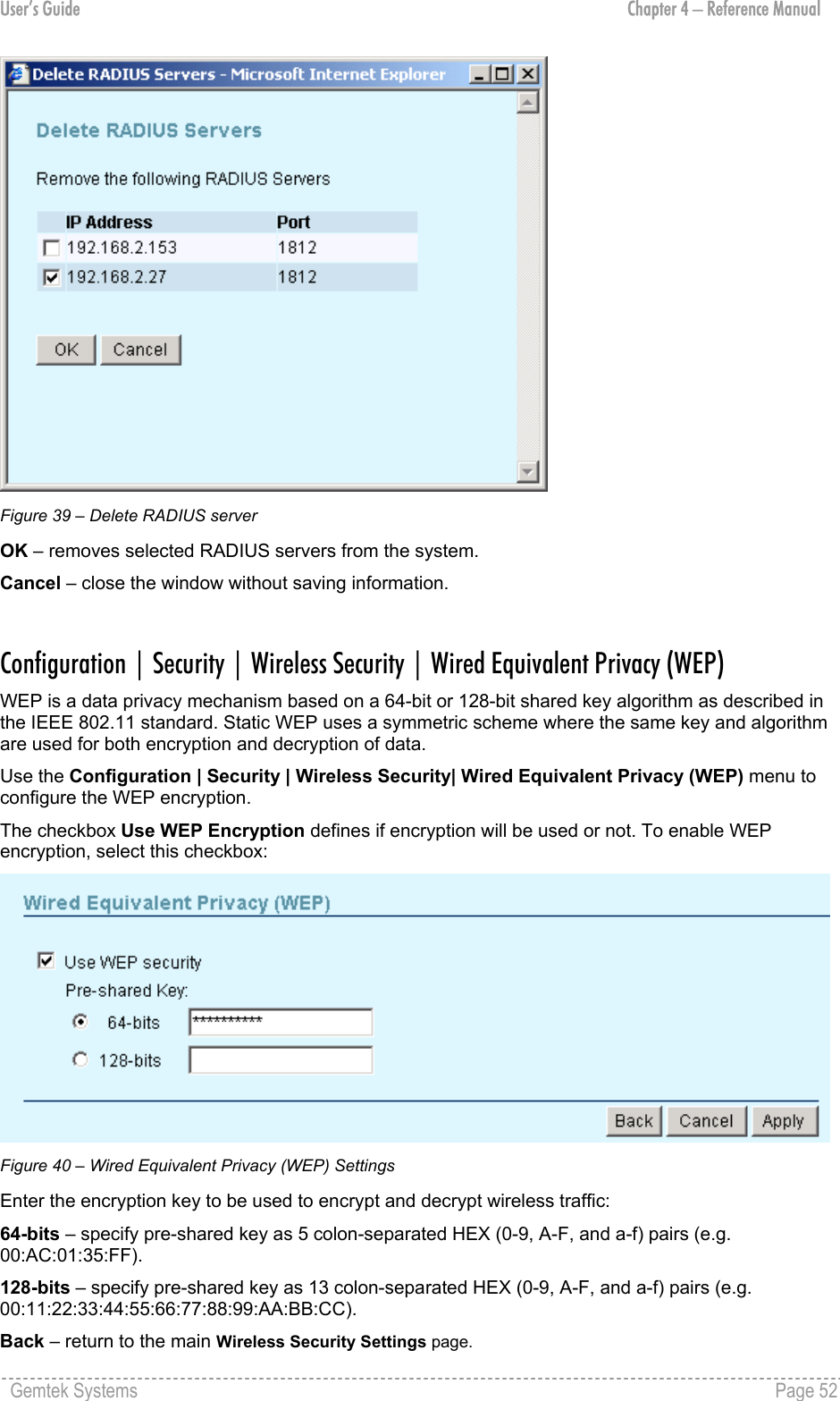
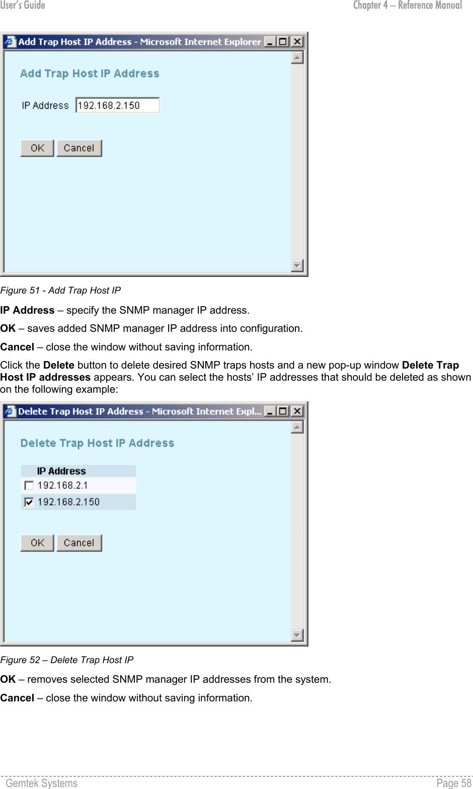
![User’s Guide Chapter 4 – Reference Manual Figure 38 – Add RADIUS Server Server Type – select the RADIUS server’s type [authentication/accounting]. IP Address – enter the RADIUS server IP address [digit and dots]. UDP Port – specify the network port used to communicate with RADIUS [1-65535]. Default: 1812. The port default value is 1812 in accordance with RFC 2865 " Remote Authentication Dial-in User Service (RADIUS)". Secret – specify the shared secret string that is used to encrypt data frames used for RADIUS servers [4-64 symbols]. Confirm Secret – re-enter the RADIUS secret to verify its accuracy. OK – saves added new RADIUS server into configuration. Cancel – close the window without saving information. Click the Delete button to delete desired RADIUS server, and new pop-up window Delete RADIUS Servers appears. You can select the RADIUS server that should be deleted as shown on the following example: Gemtek Systems Page 51](https://usermanual.wiki/GemTek-Technology/AP930301G.User-Manual/User-Guide-415577-Page-51.png)
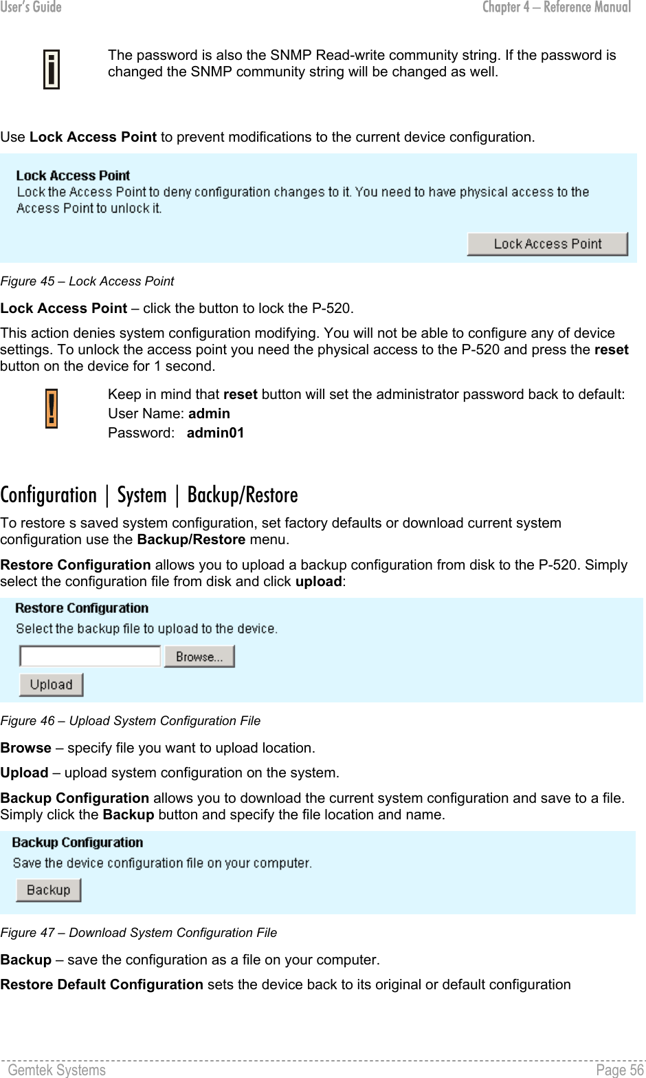
![User’s Guide Chapter 4 – Reference Manual Cancel – restore all previous values. Apply – save changed configuration. The same encryption key must also be entered into the WLAN card configuration of the mobile clients. Configuration | Security | Wireless Security | 802.1x Security 802.1X security is available only if RADIUS server is configured on the P-520 system. Use the Configuration | Security | Wireless Security| 802.1x Security menu to setup the 802.1X security settings. This security always uses dynamic WEP keys which length you can choose by simply selecting the radio button. To enable 802.1x security, select the checkbox and choose the desired Key Size and settings for Rekeying: Figure 41 – 802.1X Security Settings Key Size and Group Rekeying unavailable when using WEP security. 64-bits – indicates that a 64-bit key is chosen for 802.1x security. 128-bits – indicates that a 128-bit key is chosen for 802.1x security. No rekeying – indicates that Group Key will not be changed dynamically. Rekey every … minutes – specify the time period in minutes, after which the group key will be updated [1-71582788]. Default value is 60 minutes. Rekey every … x1000 packets – specify the number of transmitted packets, per 1000 packets, after which the group key value will be updated [1-4294967295]. Default value is 10x1000 packets. Gemtek Systems Page 53](https://usermanual.wiki/GemTek-Technology/AP930301G.User-Manual/User-Guide-415577-Page-53.png)
![User’s Guide Chapter 4 – Reference Manual Configuration | Security | Wireless Security | Wi-Fi Protected Access (WPA) Wi-Fi Protected Access provides a higher level of protection for wireless LAN client stations as it includes methods for mutual authentication, strong encryption, and data integrity. WPA takes the original master key only as a starting point and derives its encryption keys dynamically from this master key. WPA regularly changes and rotates the encryption keys so that the same encryption key is never used twice. Key exchange is done automatically transparent to the user. To enable the WPA security for your WLAN you need: An access point that has WPA support like the Gemtek Systems P-520 A wireless network card with WPA ready driver A supplicant that supports WPA (e.g. Windows XP client) To configure the WPA with pre-shared key security on the P-520 use the Configuration | Security | Wireless Security| Wi-Fi Protected Access (WPA) menu, select the WPA with pre-shared key security method and enter the shared secret: Figure 42 – WPA with Pre-shared Key Settings Pre-shared Key – specify the pre-shared key for WPA security [8-63 characters]. Re-enter Pre-shared Key – re-enter pre-shared key to verify its accuracy. The pre-shared key must match the one configured on your WLAN client stations. Back – return to the main Wireless Security Settings page. Cancel – restore all previous values. Apply – save changed configuration. WPA with RADIUS server makes use of external AAA (RADIUS) server to generate and exchange dynamic WPA keys between P-520 and the client stations. To configure WPA with a RADIUS server select the WPA with RADIUS server security method radio button and enter the Group Key Rekey settings: Gemtek Systems Page 54](https://usermanual.wiki/GemTek-Technology/AP930301G.User-Manual/User-Guide-415577-Page-54.png)
![User’s Guide Chapter 4 – Reference Manual Figure 43 – WPA with RADIUS Server Settings No rekeying – indicates that Group Key will not be rekeyed. Rekey every … minutes – specify amount of minutes and WPA automatically will generate a new Rekey every … minutes – specify the time period in minutes, after which the group key will be updated [1-71582788]. Default value is 60 minutes. Rekey every … x1000 packets – specify the number of transmitted packets, per 1000 packets, after which the group key value will be updated [1-4294967295]. Default value is 10x1000 packets. Update Group Key if station leaves BSS – when selected, the group key value will be updated if wireless client leaves BSS. Configuration | Security | Wireless Security | Management Security Use the Configuration | Security | Wireless Security | Management Security menu for changing the administrator’s password and to lock the access point for any further configuration changes. The default administrator settings for all access point interfaces are: username - admin password - admin01 The username is not configurable parameter, so it cannot be changed. Figure 44 – Change Administrator's Password New Password – specify new password value used for user authentication in the system [4-32 characters]. Confirm Password – re-enter the new password to verify its accuracy. Change Password – changes new specified administrator’s password. Gemtek Systems Page 55](https://usermanual.wiki/GemTek-Technology/AP930301G.User-Manual/User-Guide-415577-Page-55.png)
![User’s Guide Chapter 4 – Reference Manual Status Status | Statistics/Usage | Status Overview Use the Status | Statistics/Usage | Status Overview menu for a summary of status information of your access point. Figure 53 – Status Overview Uptime – indicates the time, expressed in hours, minutes and seconds since last reboot [hours:minutes:seconds]. Wireless Clients – indicates the total number of currently connected client stations. Click on the hyperlink Status | Clients | Wireless Clients to see more details for individual clients. Packets Sent – indicates the data volume transmitted to the wireless LAN since reboot. Packets Received – indicates the volume of data received since reboot. Last Log – indicates the time when the access point has sent the most recent event message. Highest Priority – shows the priority level of the last event [Emergency/Alert/Critical/Error/Warning/Notice/Info/Debug]. Status | Statistics/Usage | Interface Statistics Use the Status | Statistics/Usage | Interface Statistics menu for a summary of interface statistics. Figure 54 – Interface Statistics Gemtek Systems Page 59](https://usermanual.wiki/GemTek-Technology/AP930301G.User-Manual/User-Guide-415577-Page-59.png)
![User’s Guide Chapter 4 – Reference Manual Interface – indicates a unique name for each interface. Status – shows the current operational state of the interface [up/down]. InOctets – indicates the amount of received bytes on the interface, including framing characters. InUcast – totals unicast frames received at the port excluding discards. InMcast – totals multicast frames received at the port excluding discards. OutOctets – shows the total transmitted frames of the interface in bytes, including framing characters. OutUcast – totals unicast frames transmitted from the port including discards. OutMcast – totals multicast frames transmitted from the port including discards. Status | Statistics/Usage | Wireless Statistics Use the Status | Statistics/Usage | Wireless Statistics menu to view information regarding data traffic for the Wireless interface. Figure 55 – Wireless Statistics Transmitted Fragments – displays the total of transmitted fragmented frames. Transmitted Multicasts – displays the total of transmitted multicast frames. Transmitted Frame Count – displays count of successfully transmitted MSDU (MAC Service Data Units). Failed Packets – displays the total of not transmitted MSDU. Retry Count – displays the number of successfully transmitted MSDU after one or more retransmissions. Multiple Retry Count – displays the number of successfully transmitted MSDU after more than one retransmissions. Duplicate Frames – displays the total of duplicate frames. RTS Success Count – displays the total of successfully received RTS packets. RTS Failure Count – displays total of not received RTS packets. Gemtek Systems Page 60](https://usermanual.wiki/GemTek-Technology/AP930301G.User-Manual/User-Guide-415577-Page-60.png)
![User’s Guide Chapter 4 – Reference Manual ACK Failure Count – displays total of expected but not received ACK (acknowledgement) frames. Received Fragment Count – displays total of each successfully received MPDU (MAC Protocol Data Unit) of type Data or Management. Received Multicasts Count – displays the total of MSDU, received with the multicast bit set in the destination MAC address. FCS Errors – displays count of FCS (Frame Check Sequence) errors in received MPDU. WEP Undecryptable – displays the number of not decrypted frames. Status | Statistics/Usage | Event Reporting The event reporting system informs about internal services and provides debug messages in case of malfunctions or network problems. The trace system can help operators to locate mis-configurations and system errors. Use the Status | Statistics/Usage | Event Reporting menu to view current syslog messages in case of troubleshooting of one of the services: Figure 56 – Event Reporting Reset Eventlog – delete all displayed logged messages. Report Level – shows how important the event (or how critical the error) is [Emergency/Alert/Critical/Error/Warning/Notice/Info/Debug]. Facility – indicates the unique identifier of the facility that generated the event. A facility can be a hardware device, a protocol, or a module of the system software. [Kernel/User/Security/Clock/LogAudit/LogAlert/System/Network/Wlan/management] ID – indicates an internal number for the event. Gemtek Systems Page 61](https://usermanual.wiki/GemTek-Technology/AP930301G.User-Manual/User-Guide-415577-Page-61.png)
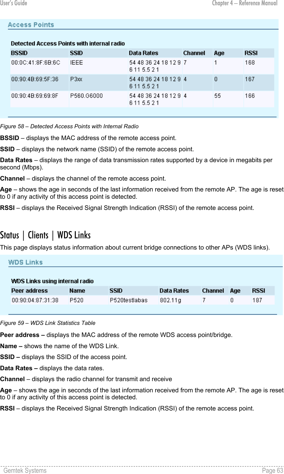
![User’s Guide Chapter 4 – Reference Manual Description – indicates description of the event. Count – indicates the number of times this event has occurred. Occurrence – indicates time when this event has occurred, in months, days and hours:minutes:seconds since the access point was started. Status | Clients | Wireless Clients All clients currently connected to the P-520 access point are listed in the Wireless Clients table. Select the Status | Clients | Wireless Clients menu if you want to get statistics regarding wireless clients. The wireless clients are listed by their MAC address, Rate, Quality, RSSI, State and Age parameters: Figure 57 – Connected Wireless Clients MAC Address – displays wireless client’s MAC address. Rate – displays the current data rate in Mbps. Quality – displays an indicator for the quality of the client (not supported yet). RSSI – displays the Received Signal Strength Indication (RSSI) in dBm of the client. State – displays the connection status between client and AP [Disconnected/ DiscAndUlPreauth/ llAuthenticated/ llAuthAndUlPreauth/ Associated/ ulAuthenticated/ Key Distribution/Forwarding/ Rejected]. Only clients in the state Forwarding will be able to send/receive data to/from other devices. Age – shows the age in seconds of the last information received from the client. The age is reset to 0 if any activity of this client is detected. Status | Clients | Access Points The page shows information about other wireless LANs in range. With this site survey administrator can scan for neighboring access points; check their operating channels, view MAC addresses, Data rates, and other parameters. The site survey does not interrupt any client or WDS connection. Gemtek Systems Page 62](https://usermanual.wiki/GemTek-Technology/AP930301G.User-Manual/User-Guide-415577-Page-62.png)