GemTek Technology AP931229AG1 2.4GHz/5GHz Outdoor Access Point User Manual manual
Gemtek Technology Co., Ltd. 2.4GHz/5GHz Outdoor Access Point manual
UserManual.wiki
>
GemTek Technology
>
AP931229AG1 User Manual
manual
Navigation menu
Upload a User Manual
Namespaces
Wiki Guide
HTML
PDF
Info
Views
User Manual
Discussion / Help
Navigation

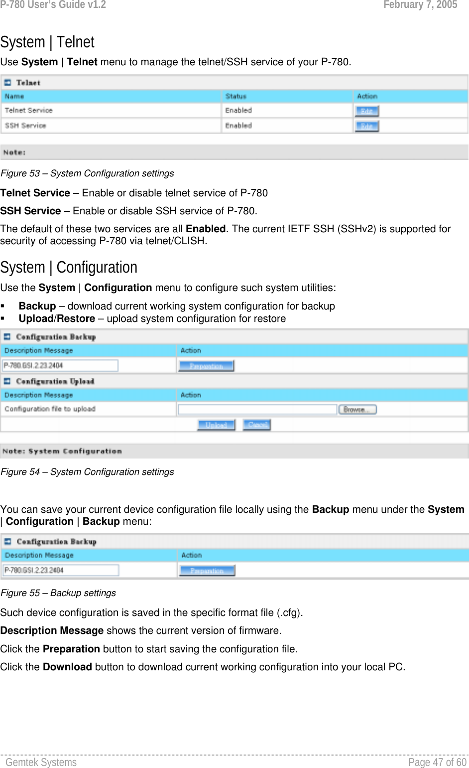
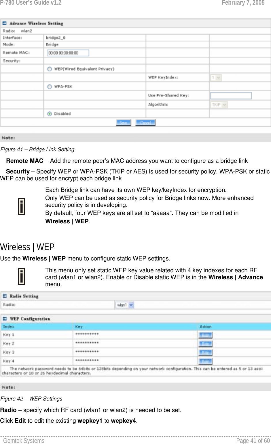
![P-780 User’s Guide v1.2 February 7, 2005 Gemtek Systems Page 8 of 60 Purpose This document provides information and procedures on hardware installation, setup, configuration, and management of the Gemtek Systems high performance 54Mb Dual-Band Outdoor AP P-780. Prerequisite Skills and Knowledge To use this document effectively, you should have a working knowledge of Local Area Networking (LAN) concepts and wireless Internet access infrastructures. In addition, you should be familiar with the following: Hardware installers should have a working knowledge of basic electronics and mechanical assembly, and should understand related local building codes. Network administrators should have a solid understanding of software installation procedures for network operating systems under Microsoft Windows 95, 98, Millennium, 2000, NT, and Windows XP and general networking operations and troubleshooting knowledge. Conventions Used in this Document The following typographic conventions and symbols are used throughout this document: Very important information. Failure to observe this may result in damage. Important information that should be observed. Additional information that may be helpful but which is not required. bold Menu commands, buttons and input fields are displayed in bold code File names, directory names, form names, and system-generated output such as error messages are displayed in constant-width type <value> Placeholder for certain values, e.g. user inputs [value] Input field format, limitations, and/or restrictions. Help Us to Improve this Document! If you should encounter mistakes in this document or want to provide comments to improve the manual please send e-mail directly to: manuals@gemtek-systems.com Gemtek Systems Technical Support If you encounter problems when installing or using this product, please consult the Gemtek Systems website at www.gemtek-systems.com for: Direct contact to the Gemtek Systems support centers. Frequently Asked Questions (FAQ). Download area for the latest software, user documentation and product updates. About this Guide](https://usermanual.wiki/GemTek-Technology/AP931229AG1/User-Guide-560809-Page-7.png)
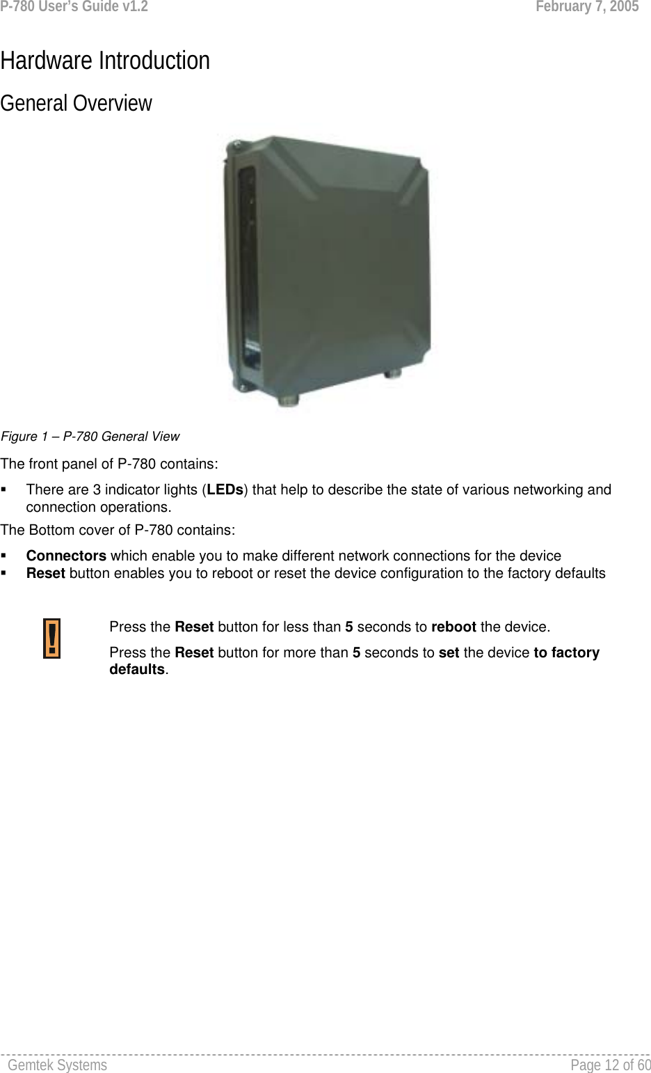

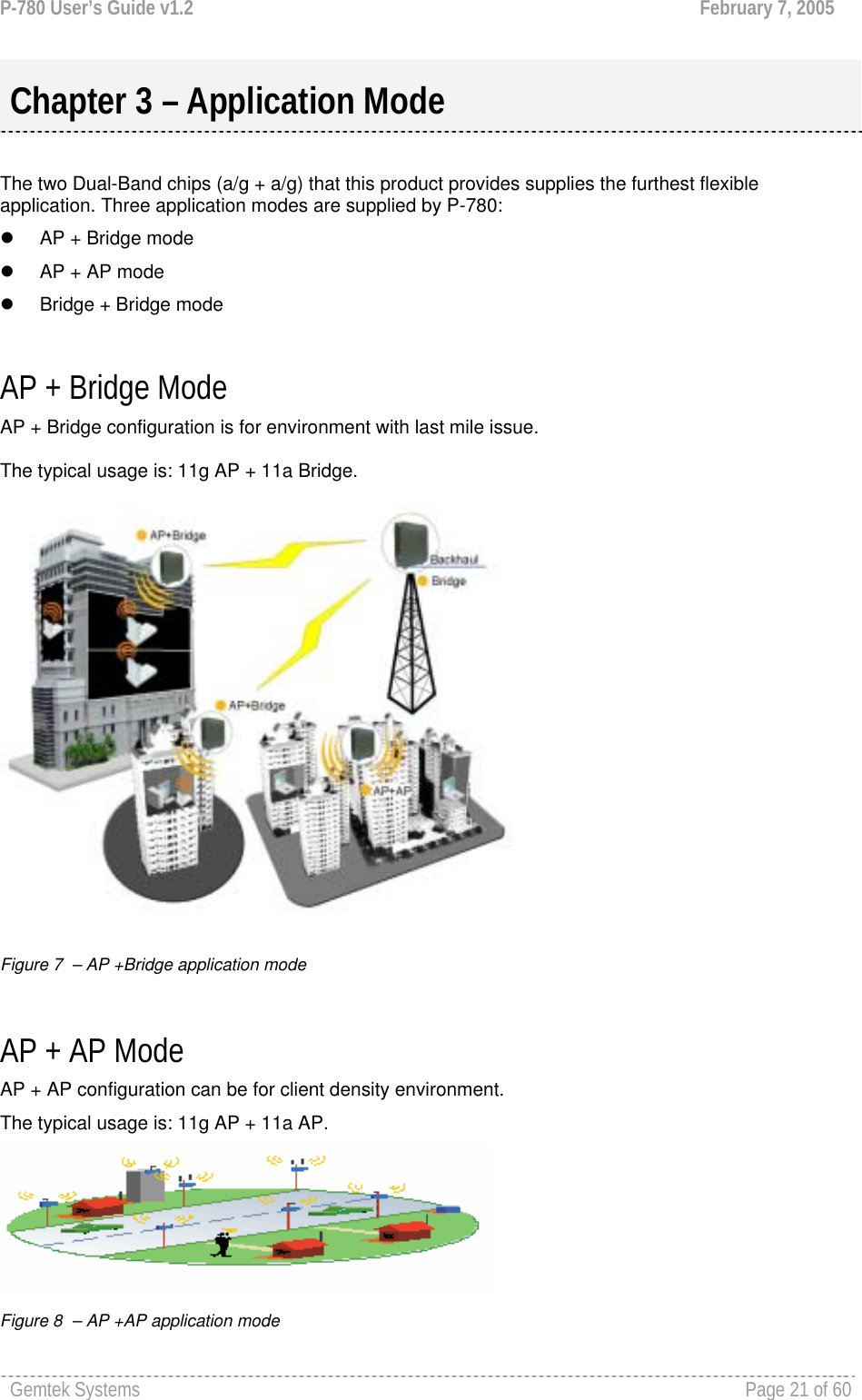
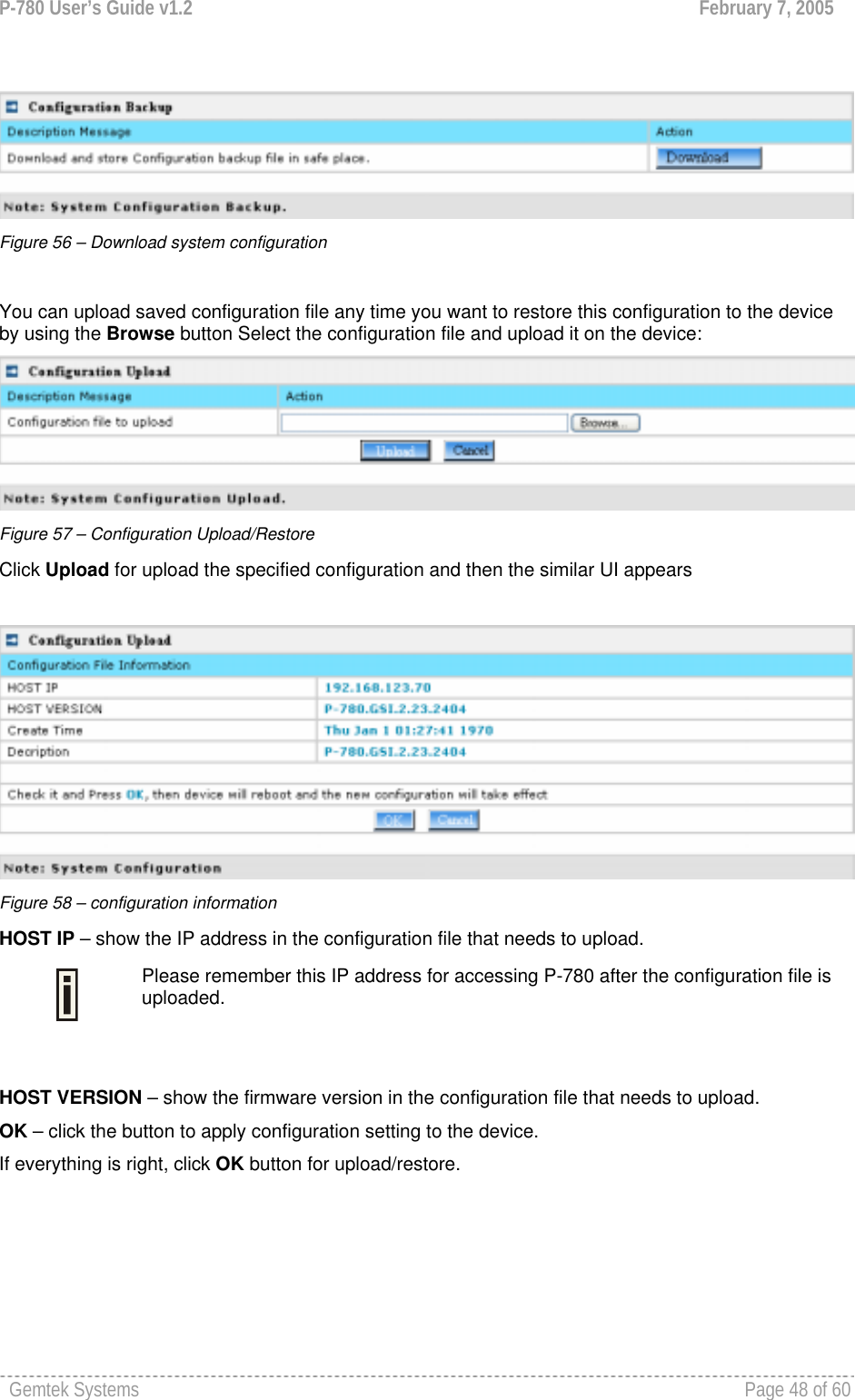
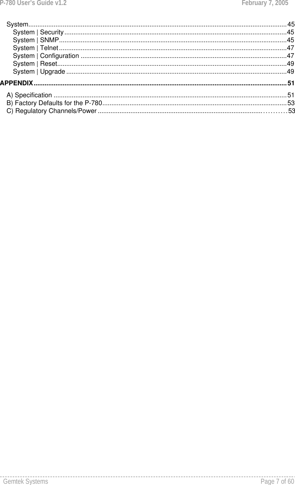
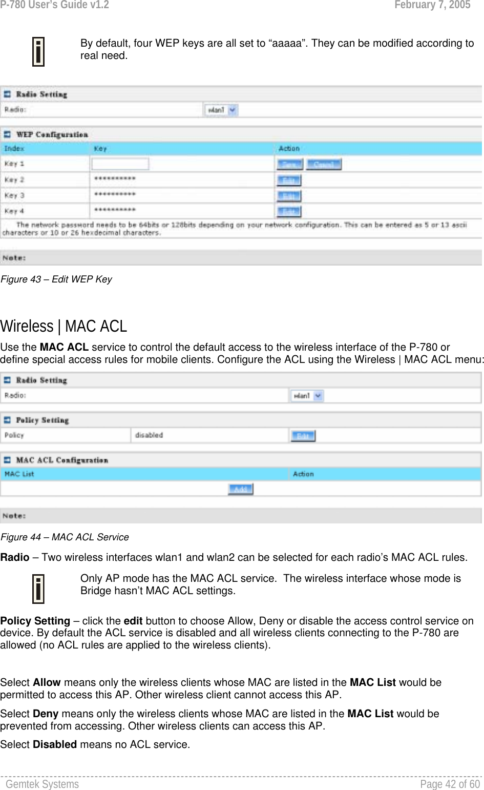
![P-780 User’s Guide v1.2 February 7, 2005 Gemtek Systems Page 26 of 60 Figure 14 – Interface Configuration Table To change network interface (bridge) configuration properties click the Edit button in the Action column. The status can be changed now: Figure 15 – Edit Interface Configuration Settings IP Address - specify new interface IP address [in digits and dots notation, e.g. 192.168.123.70]. Netmask – specify the subnet mask [[0-255].[0-255].[0-255].[0-255]].These numbers are a binary mask of the IP address, which defines IP address order and the number of IP addresses in the subnet. Gateway Address – interface gateway. For Bridge type interfaces, the gateway is always the gateway router. Protocol – specify static for setting IP address manually and dhcp for getting IP address dynamically acting as DHCP client. When dhcp is used for getting IP address, Kickstart is recommended to find your device. Save – save the entered values. Cancel – restore all previous values. Change status or leave in the default state if no editing is necessary and click the Save button. Figure 16 – Apply or Discard Interface Configuration Changes Apply Changes – to save all changes in the interface table at once. Discard Changes – restore all previous values. For such each change of settings, the P-780 needs to be restarted to apply all settings changes when clicking Apply Changes. Request for reboot server appears: Figure 17 – Reboot Server Reboot – Click the button to restart the server and apply the changes.](https://usermanual.wiki/GemTek-Technology/AP931229AG1/User-Guide-560809-Page-25.png)
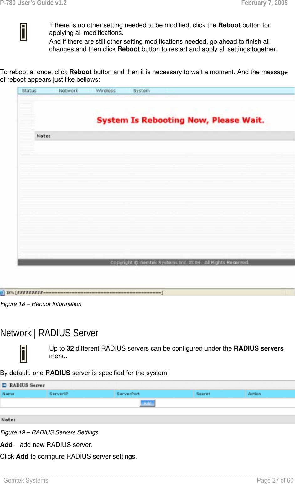
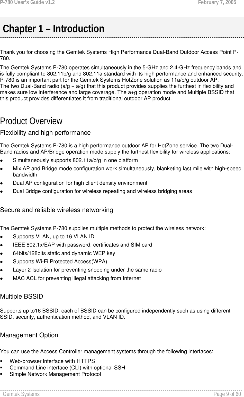
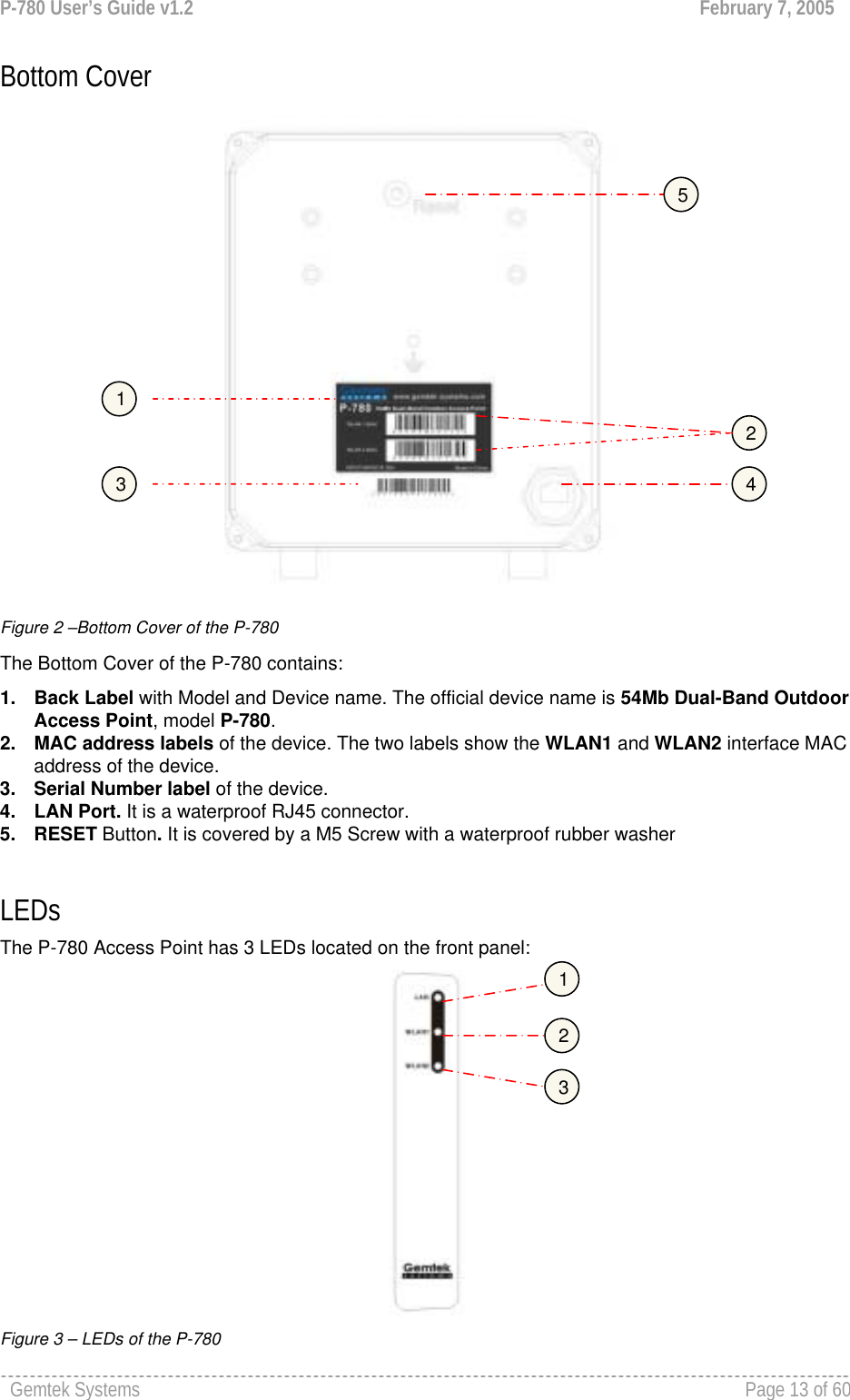
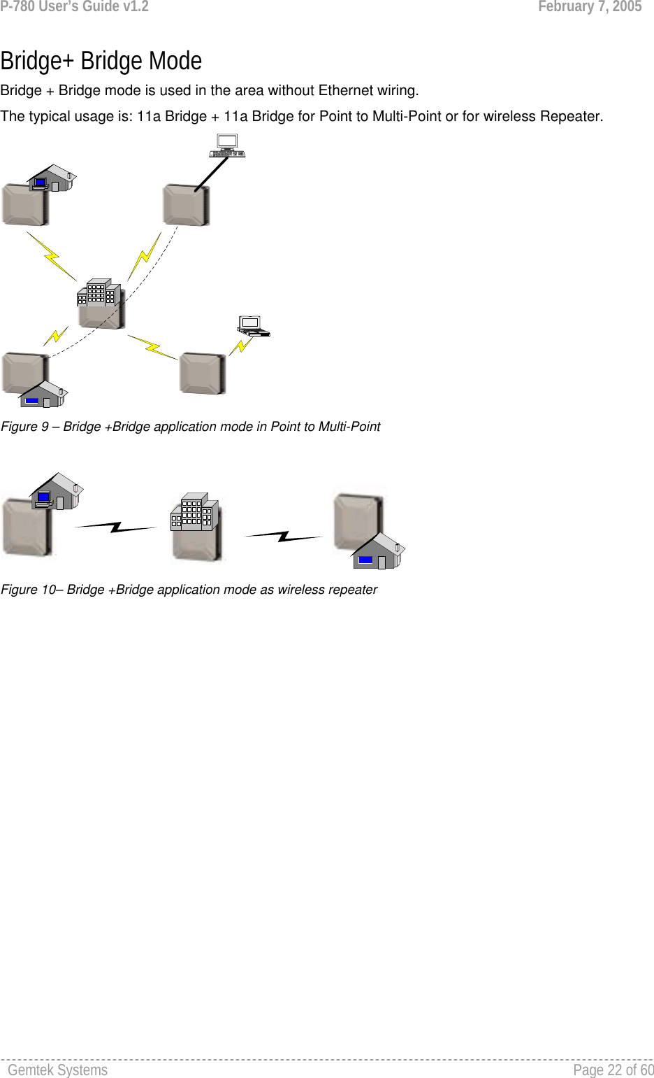
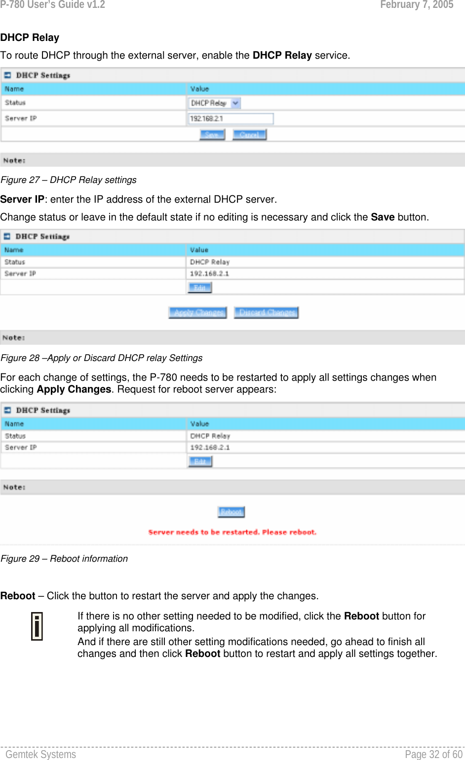
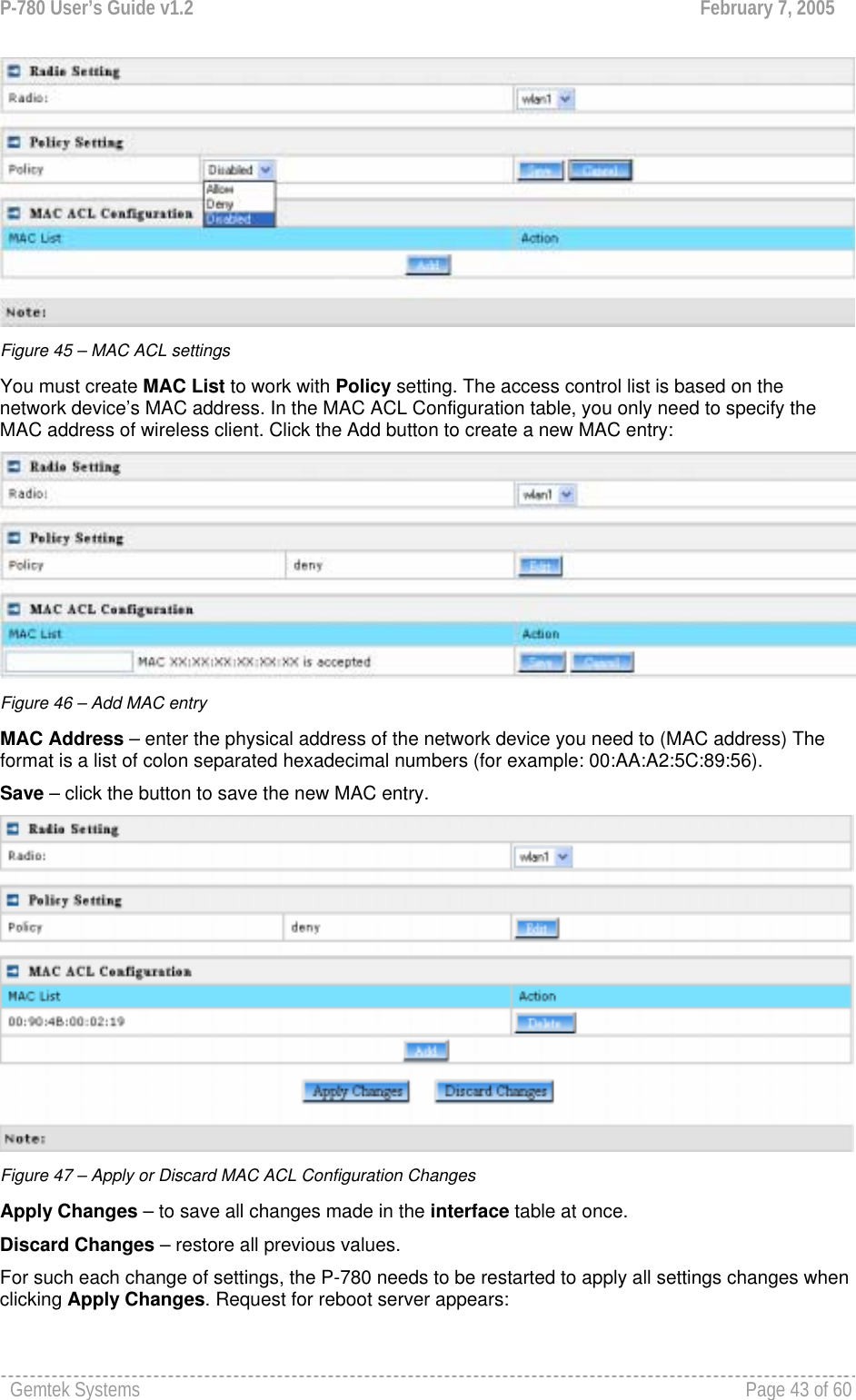
![P-780 User’s Guide v1.2 February 7, 2005 Gemtek Systems Page 28 of 60 Figure 20 – RADIUS Server's Details Name – specify the new RADIUS server name which is used for selecting RADIUS server. Server IP – authentication RADIUS server IP address [dots and digits]. Server Port – specify the network port used to communicate with RADIUS [1-65535]. The port default value of 1812 is based on RFC 2138 "Remote Authentication Dial-in User Service (RADIUS)". Secret – shared secret string that is used to make sure the integrity of data frames used for authentication server. Save – add new specified RADIUS server. Cancel – restore all previous values. After adding a new RADIUS server or editing an existing one, the following control appears: Edit – edit an existing RADIUS server settings Delete – delete an existing RADIUS server settings Reboot – restart the controller to make applied changes work. If there is no other setting needed to be modified, click the Reboot button for applying all modifications. And if there are still other setting modifications needed, go ahead to finish all changes and then click Reboot button to restart and apply all settings together. Network | DHCP Settings P-780 can act as DHCP server or DHCP relay. The DHCP (Dynamic Host Configuration Protocol) service is supported on physical interfaces.](https://usermanual.wiki/GemTek-Technology/AP931229AG1/User-Guide-560809-Page-27.png)
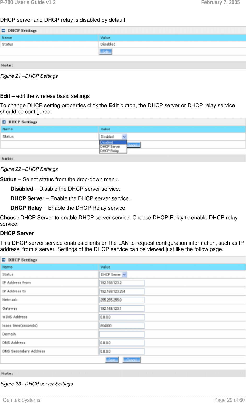
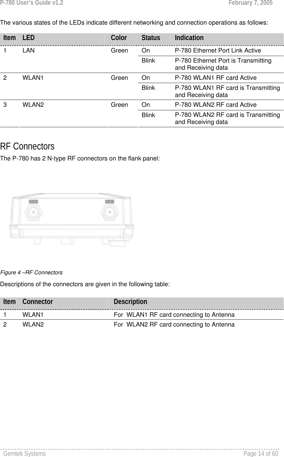
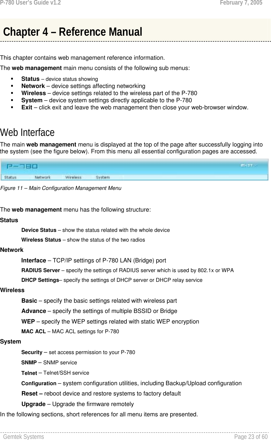
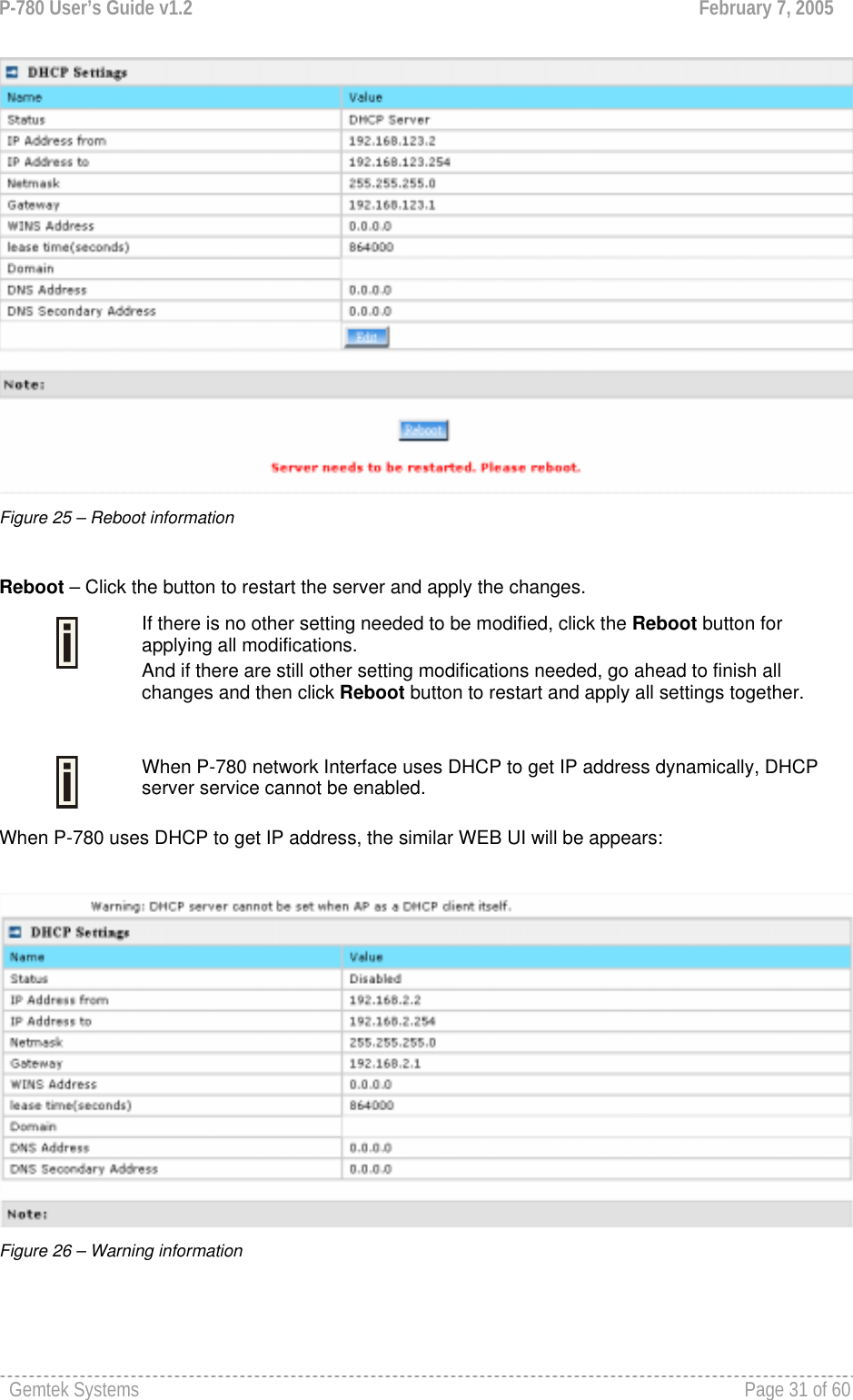
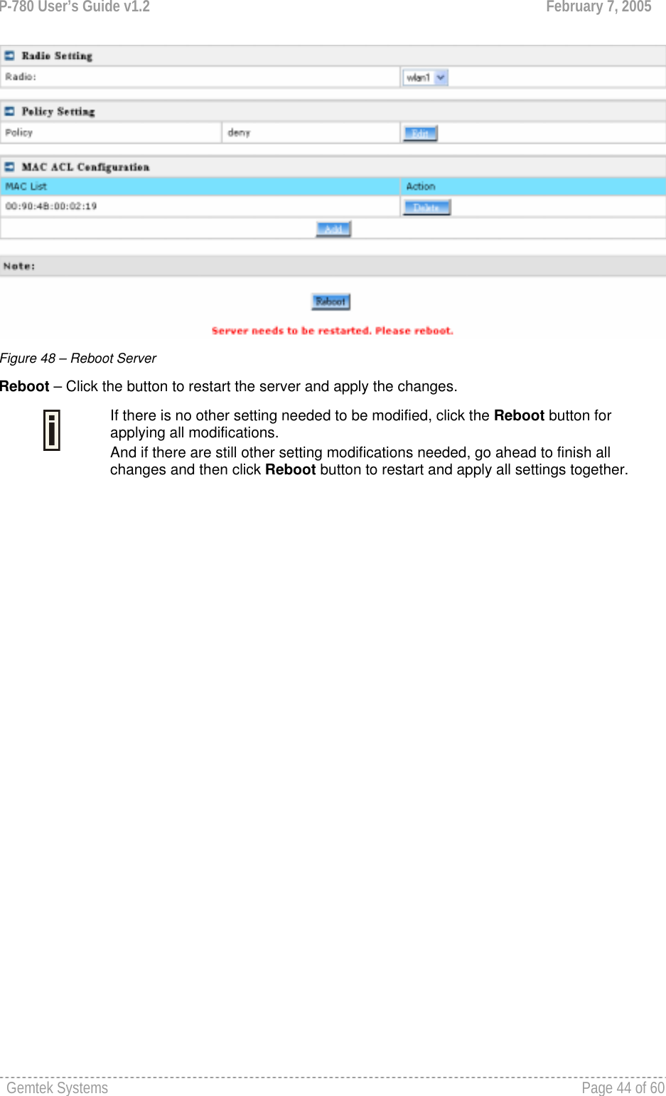
![P-780 User’s Guide v1.2 February 7, 2005 Gemtek Systems Page 30 of 60 By default, DHCP server is disabled for P-780. IP Address from / IP Address to – specify the IP address range to be dynamically allocated by the DHCP server. Netmask – enter the netmask for IP pool range. Gateway – enter the gateway IP for wireless clients. WINS Address (Windows Internet Naming Service) – specify server IP address if it is available on the network [dots and digits]. Lease Time – specify the IP address lease interval in seconds [1-1000000]. DNS address – specify the DNS server’s IP address [in digits and dots notation]. DNS secondary address – specify the secondary DNS server’s IP address [in digits and dots notation]. Change status or leave in the default state if no editing is necessary and click the Save button. Figure 24 –Apply or Discard DHCP server Settings The DHCP server settings will be automatically adjusted to match the network interface settings. The Gateway of DHCP server settings must be same with the Gateway of P-780 For each change of settings, the P-780 needs to be restarted to apply all settings changes when clicking Apply Changes. Request for reboot server appears:](https://usermanual.wiki/GemTek-Technology/AP931229AG1/User-Guide-560809-Page-29.png)
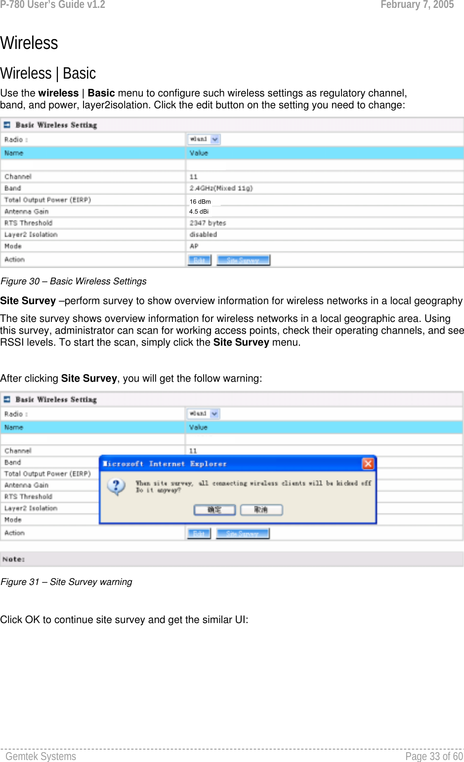
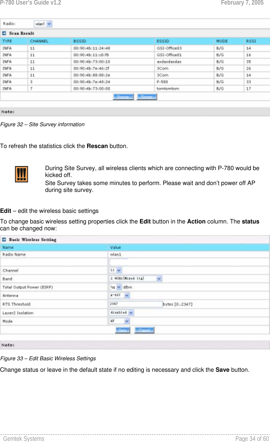
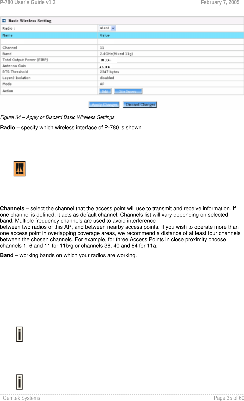
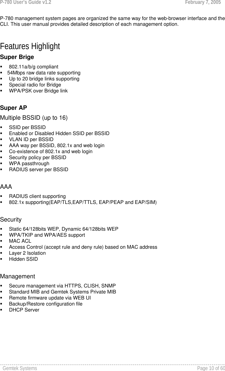
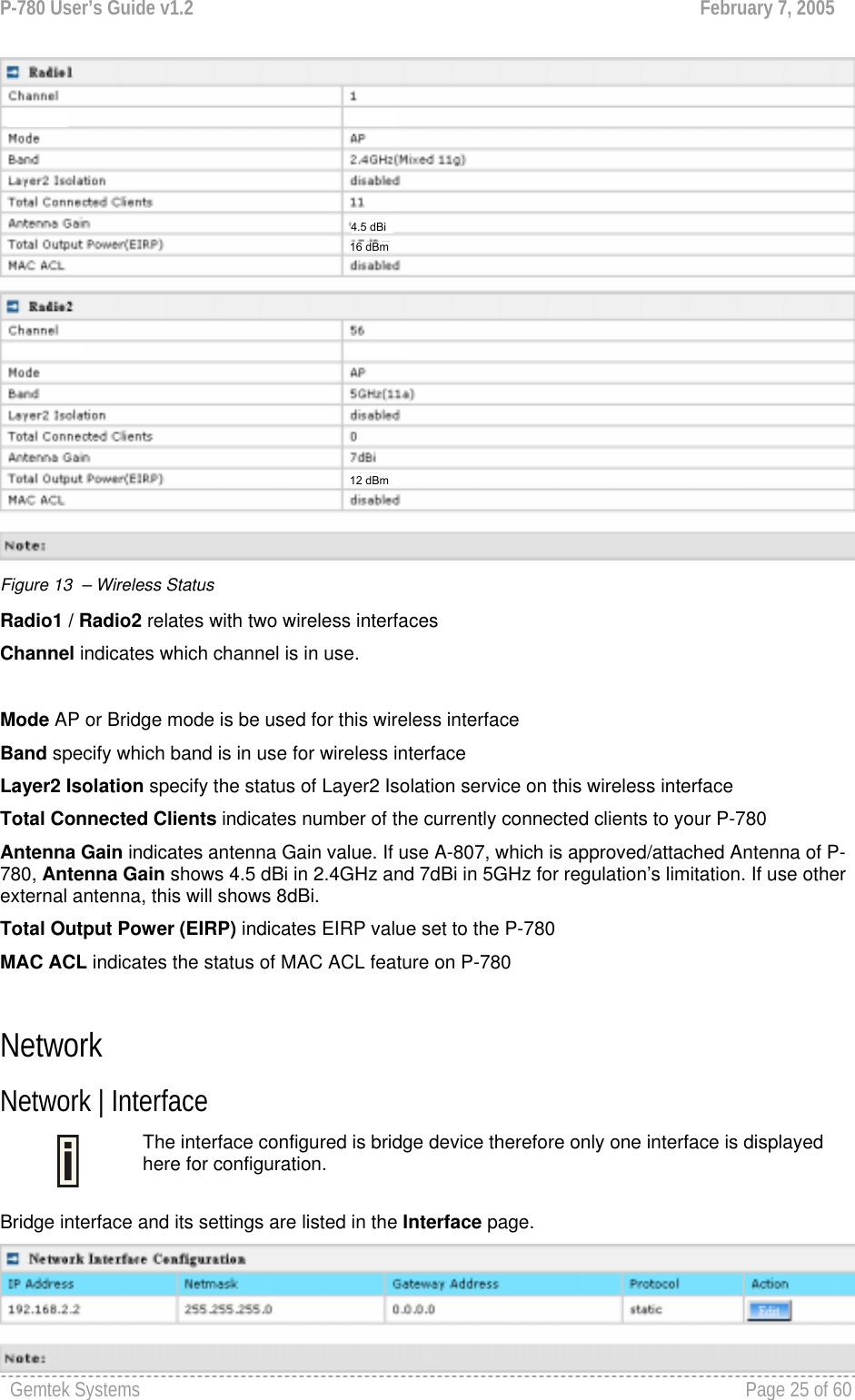
![P-780 User’s Guide v1.2 February 7, 2005 Gemtek Systems Page 36 of 60 Antenna Gain: When using the approved antenna supplied by Gemtek System, you must select the Antenna A-807 in Antenna item to meet the regulation’s power limitation. A-807 is 4.5dBi in 2.4GHz, 7dBi in 5GHz. A-807 antenna is the accessory of P-780 Product. RTS Threshold – when set, this settings specifies the maximum packet size beyond which RTS/CTS mechanism is be invokes. The value range of this is [0 …2347]. Default is 2346 which means that RTS is disabled. Layer 2 Isolation – Layer2 wireless client separation. Connected clients with user isolation function enabled cannot access each other directly. The clients are isolated from each other using their MAC addresses [enabled/disabled]. Mode – two modes are supplied: AP mode and Bridge mode. For such each change of settings, the P-780 needs to be restarted to apply all settings changes when clicking Apply Changes. Request for reboot server appears: Figure 35 – Reboot Server Reboot – Click the button to restart the server and apply the changes. If there is no other setting needed to be modified, click the Reboot button for applying all modifications. And if there are still other setting modifications needed, go ahead to finish all changes and then click Reboot button to restart and apply all settings together. 16 dBm4.5 dBi](https://usermanual.wiki/GemTek-Technology/AP931229AG1/User-Guide-560809-Page-35.png)
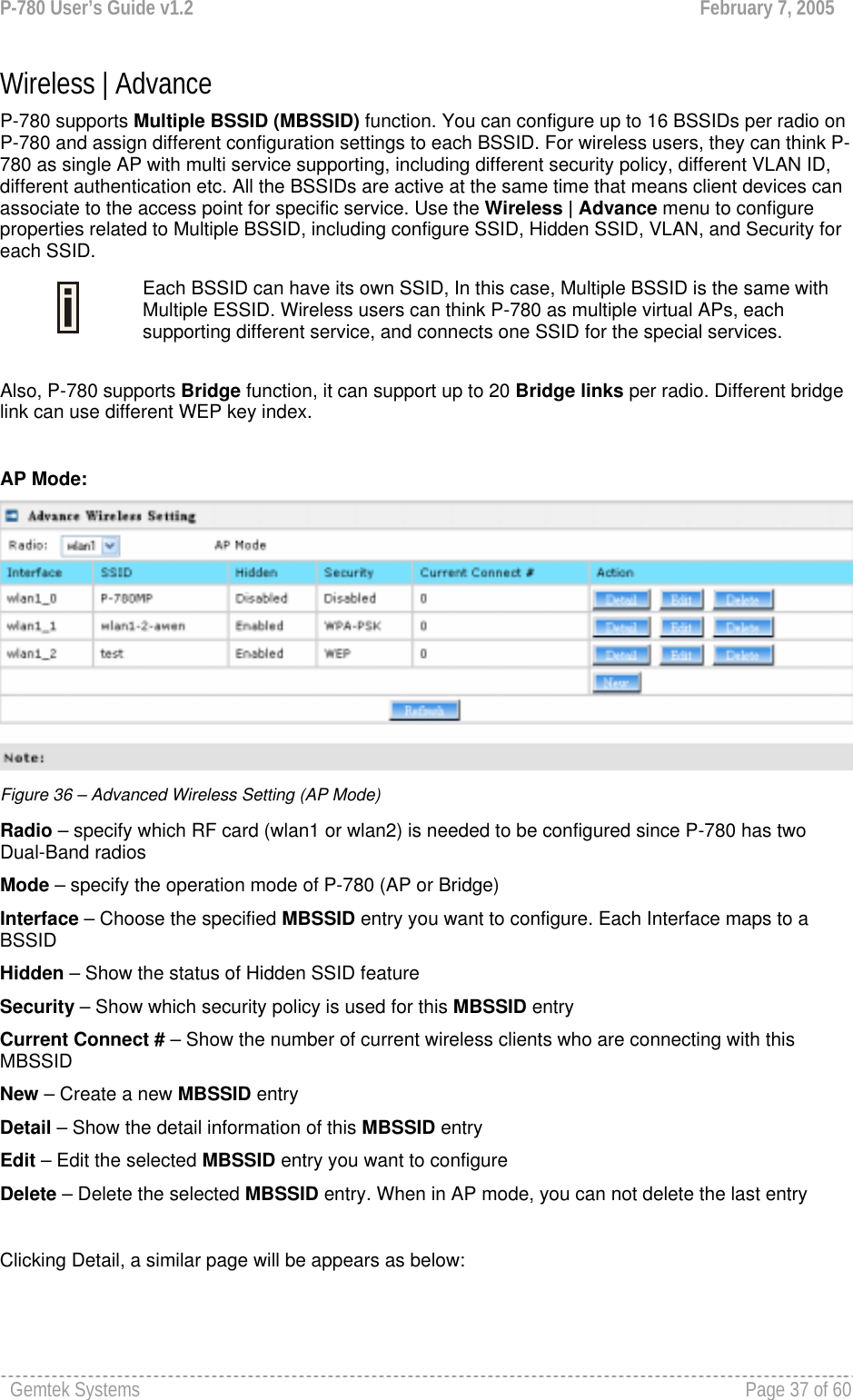
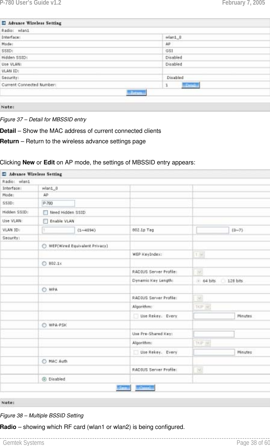
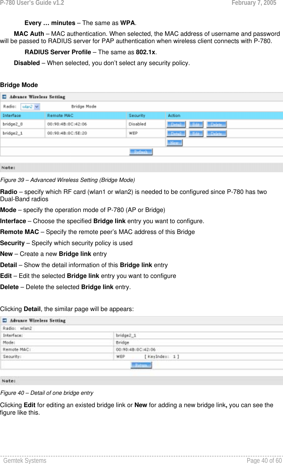
![P-780 User’s Guide v1.2 February 7, 2005 Gemtek Systems Page 39 of 60 Mode – showing the current operation mode of P-780 (AP or Bridge). Interface – showing the current MBSSID | Bridge link entry SSID – a unique ID for your wireless network. It is case sensitive and must not exceed 32 characters. The default SSID is "P-780" but you should change this to a personal wireless network name. The SSID is important for clients when connecting to the access point. All client stations must have their client SSID settings configured and must use the same SSID. Each MBSSID entry (BSSID) can has its own SSID. And SSID can be same for different BSSID Hidden SSID – When enabled, the SSID of this Interface is invisible in the networks list while scanning the available networks for wireless client (SSID is not broadcasted with its Beacons). When disabled, the AP’s SSID is visible in the available network list [enabled/disabled]. By default the Hidden SSID is disabled. Use VLAN – When enabled, the outgoing packets from this SSID device will be tagged with VLAN ID and 802.1p tag (If have). VLAN ID – Configure VLAN ID for each Multiple SSID devices. Valid numbers are from 1 to 4094. 802.1p Tag – Configure 802.1p Tag for remote APC’s or Router’s QoS uses. Valid numbers are from 0 to 7. VLAN ID and 802.1p tag must cooperate with remote Router or APC. Security – Specify the security policy. WEP – When selected, the privacy of MSSID entry will be set to WEP (Wired Equivalent Privacy). WEP Key Index – Select the default key Index to make it the Default key and encrypt the data before being transmitted. All stations, including this MSSID Entry, always transmit data encrypted using this Default Key. The key number (1,2,3,4) is also transmitted. The receiving station will use the key number to determine which key to use for decryption. If the key value does not match with the transmitting station, the decryption will fail. The key value is set in Wireless | WEP web page. 802.1x – When selected, the MSSID entry will be configured as an 802.1x authenticator. It supports multiple authentication types based on EAP (Extensible Authentication Protocol) like EAP-TLS, EAP-TTLS, EAP-PEAP, EAP-SIM. The privacy will be configured as dynamic WEP. RADIUS Server Profile – Select the default radius server name. If not, please configure Network | RADIUS Servers Web page first. Dynamic Key Length – Select the dynamic 64-bits / 128-bits encryption. WPA – Wi-Fi Protected Access, When selected, the encrypt method will be WPA with RADIUS Sever. RADIUS Server Profile – The same as 802.1x. Algorithm – Choose WPA algorithm (TKIP, AES). Use ReKey – If not selected, indicates that Group Key will not be rekeyed. If selected, must specify the time in minutes, after which the group key will be updated. Every … minutes – Specify amount of minutes and WPA automatically will generate a new Group Key. WPA-PSK – When selected, the encrypt method will be WPA without RADIUS Server. Use Pre-Shared Key – Specify more than 8 characters and less than 64 characters for WPA with pre-shared key encryption. Algorithm – The same as WPA. Use Rekey – The same as WPA.](https://usermanual.wiki/GemTek-Technology/AP931229AG1/User-Guide-560809-Page-38.png)
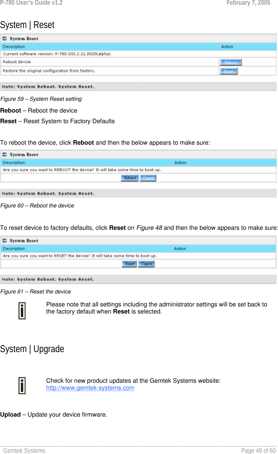
![P-780 User’s Guide v1.2 February 7, 2005 Gemtek Systems Page 45 of 60 System System | Security Use the System | Security service to configure the name and password administrator: Figure 49 – system security settings User Name – administrator username for access to P-780 (e.g. web interface, CLI mode) [1-32 symbols, spaces not allowed]. Old Password – old password value. New Password –new password value used for user authentication in the system [4-8 characters, spaces not allowed]. Confirm Password – re-enter the new password to verify its accuracy. Save – click to save new administrator settings. Default administrator logon settings are: User Name: admin Password: admin01 Password length is from 4 to 8 characters. System | SNMP SNMP is the standard protocol that regulates network management over the Internet. To communicate with SNMP manager you must set up the same SNMP communities and identifiers on both ends: manager and agent. Use the System | SNMP menu to change current SNMP configuration.](https://usermanual.wiki/GemTek-Technology/AP931229AG1/User-Guide-560809-Page-44.png)
![P-780 User’s Guide v1.2 February 7, 2005 Gemtek Systems Page 46 of 60 Figure 50 – SNMP settings Readonly community – Community name is used in SNMP version 1 and version 2c. Read-only (public) community allows reading values, but denies any attempt to change values [1-32 all ASCII printable characters, no spaces]. Readwrite community – Community name is used in SNMP version 1 and version 2c. Read-write (private) community allows to read and (where possible) change values [1-32 all ASCII printable characters, no spaces]. Default Trap community – The default SNMP community name used for traps without specified communities. The default community by most systems is "public". The community string must match the community string used by the SNMP network management system (NMS) [1-32 all ASCII printable characters, no spaces]. Trap Configuration Table: You can configure your SNMP agent to send SNMP Traps (and/or inform notifications) under the defined host (SNMP manager) and community name (optional). Figure 51 – SNMP Trap table settings Click Add to add a new SNMP manager or Delete to delete a specific SNMP manager. Clicking Add: Figure 52 – Add SNMP Trap Host IP – enter SNMP manager IP address [dots and digits]. Host Port – enter the port number the trap messages should be send through [number]. Trap Type – select trap message type [v1/v2/inform]. Community – specify the community name at a SNMP trap message. This community will be used in trap messages to authenticate the SNMP manager. If not defined, the default trap community name will be used (specified in the SNMP table) [1-32 all ASCII printable characters, no spaces]. Save – save all current settings Cancel – restore the last settings](https://usermanual.wiki/GemTek-Technology/AP931229AG1/User-Guide-560809-Page-45.png)