GemTek Technology C920730G Wireless 11g Cardbus Adapter User Manual WL 211F
Gemtek Technology Co., Ltd. Wireless 11g Cardbus Adapter WL 211F
UserManual.wiki
>
GemTek Technology
>
C920730G User Manual
Manual revised
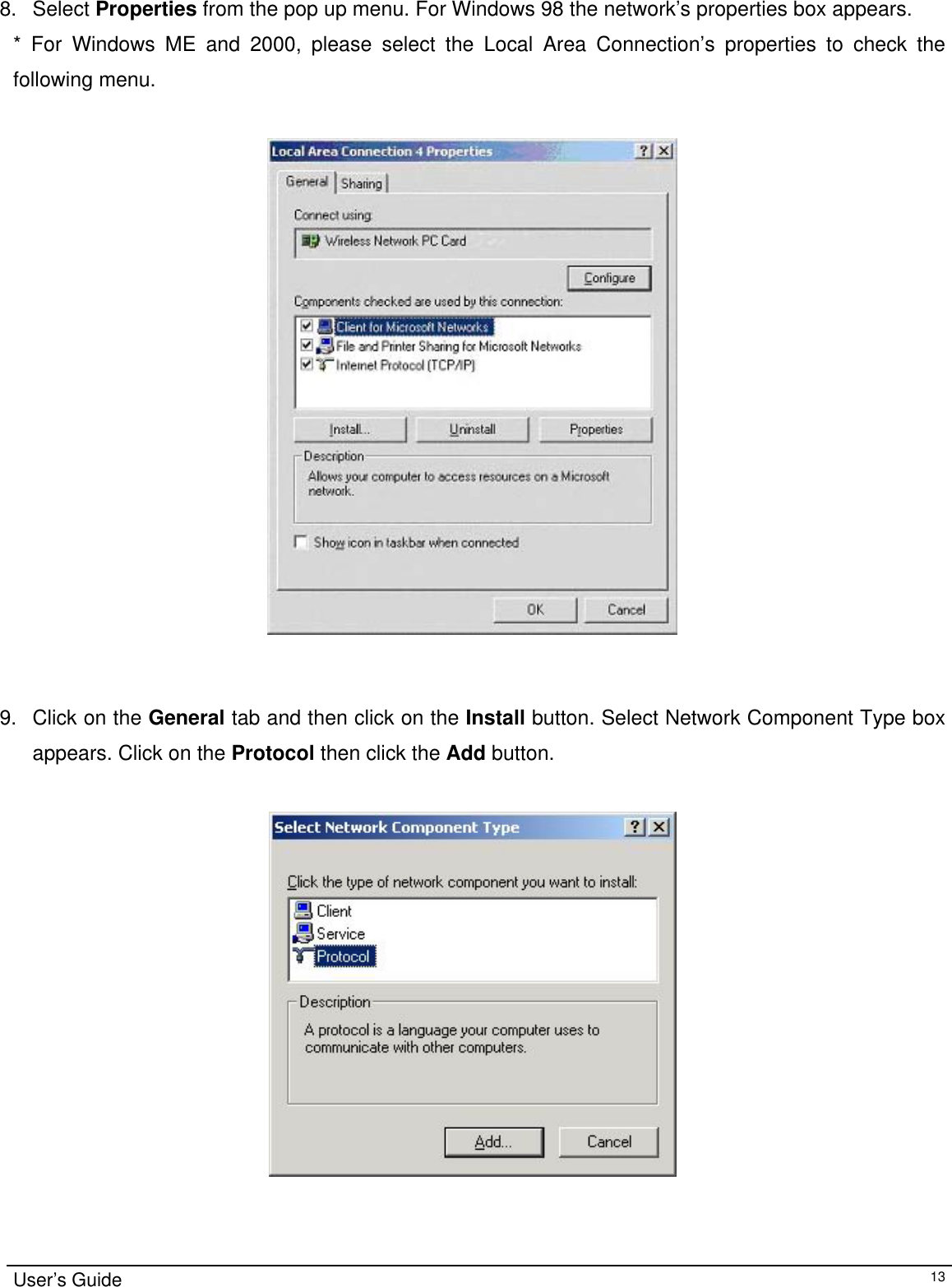
Navigation menu
Upload a User Manual
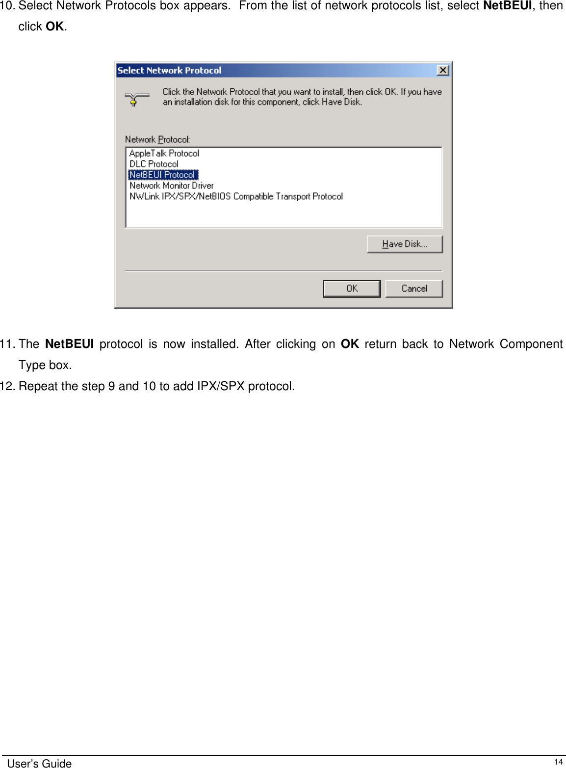
Namespaces
Wiki Guide
HTML
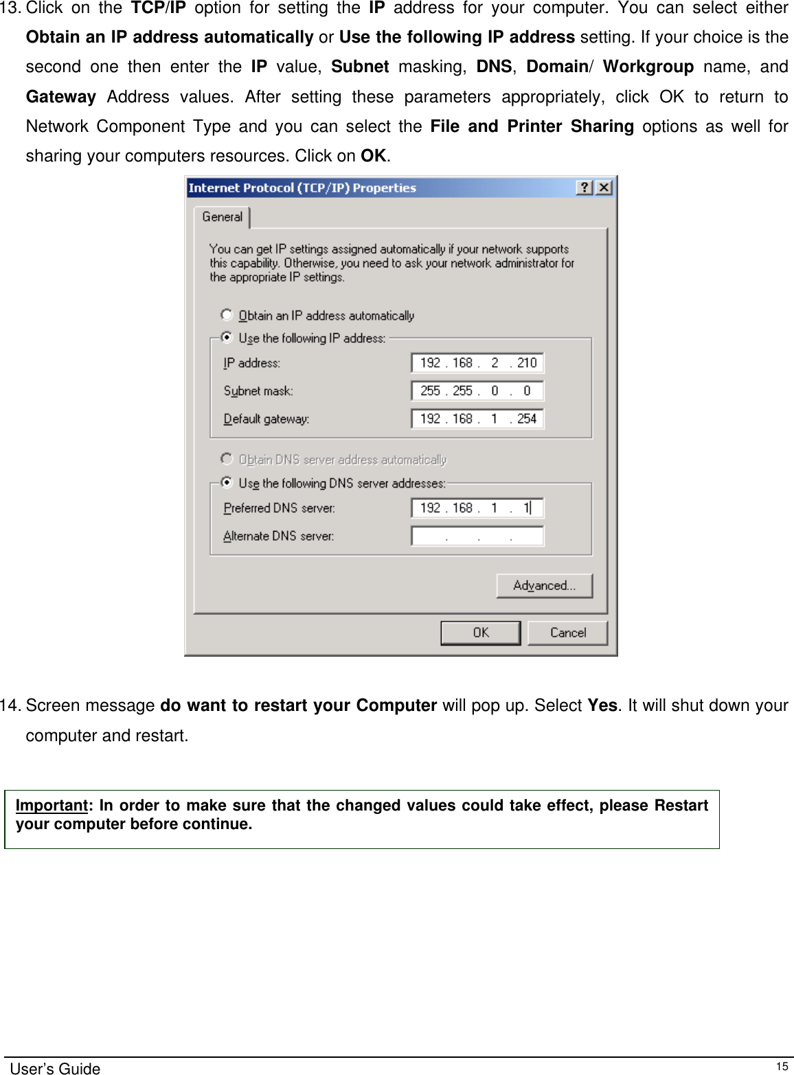
PDF
Info
Views
User Manual
Discussion / Help
Navigation