GemTek Technology MU910606 Wireless Mini USB Adapter User Manual Manual
Gemtek Technology Co., Ltd. Wireless Mini USB Adapter Manual
UserManual.wiki
>
GemTek Technology
>
MU910606 User Manual
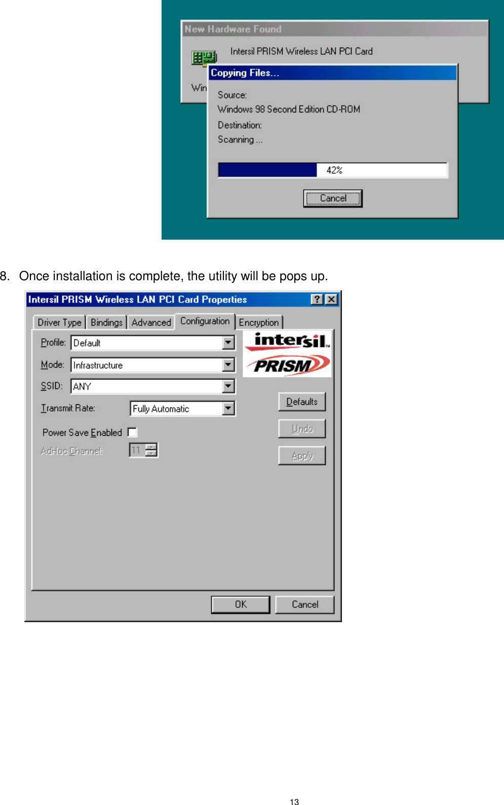
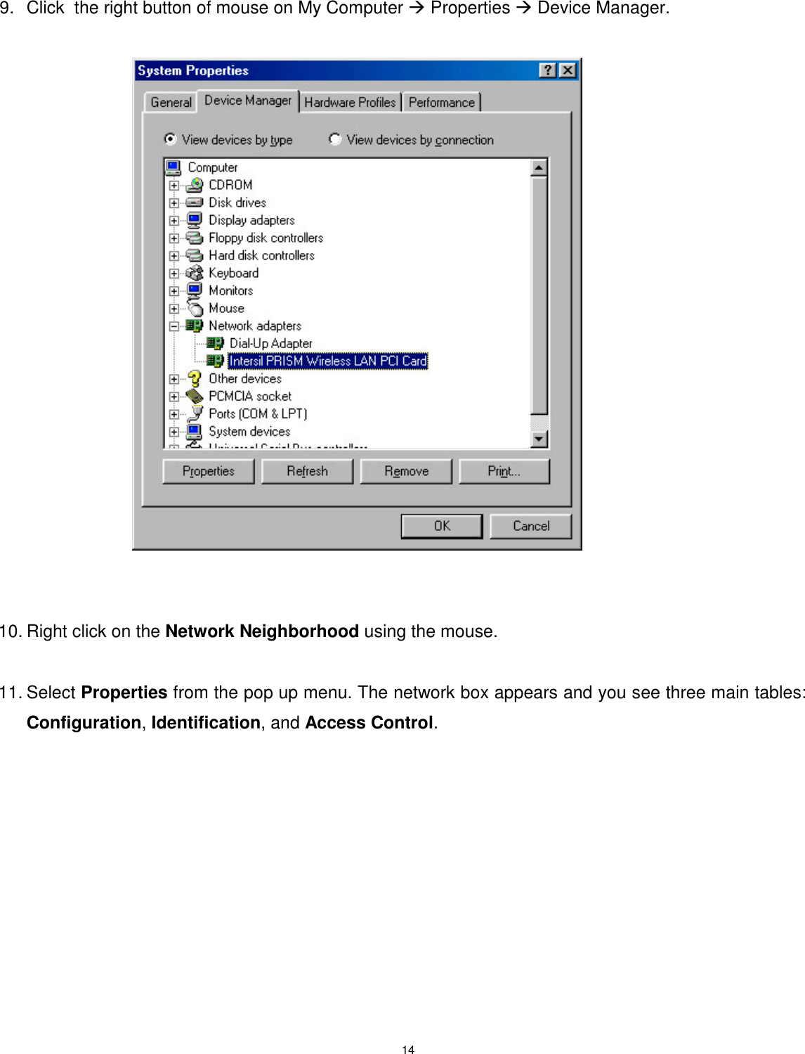
Manual
Navigation menu
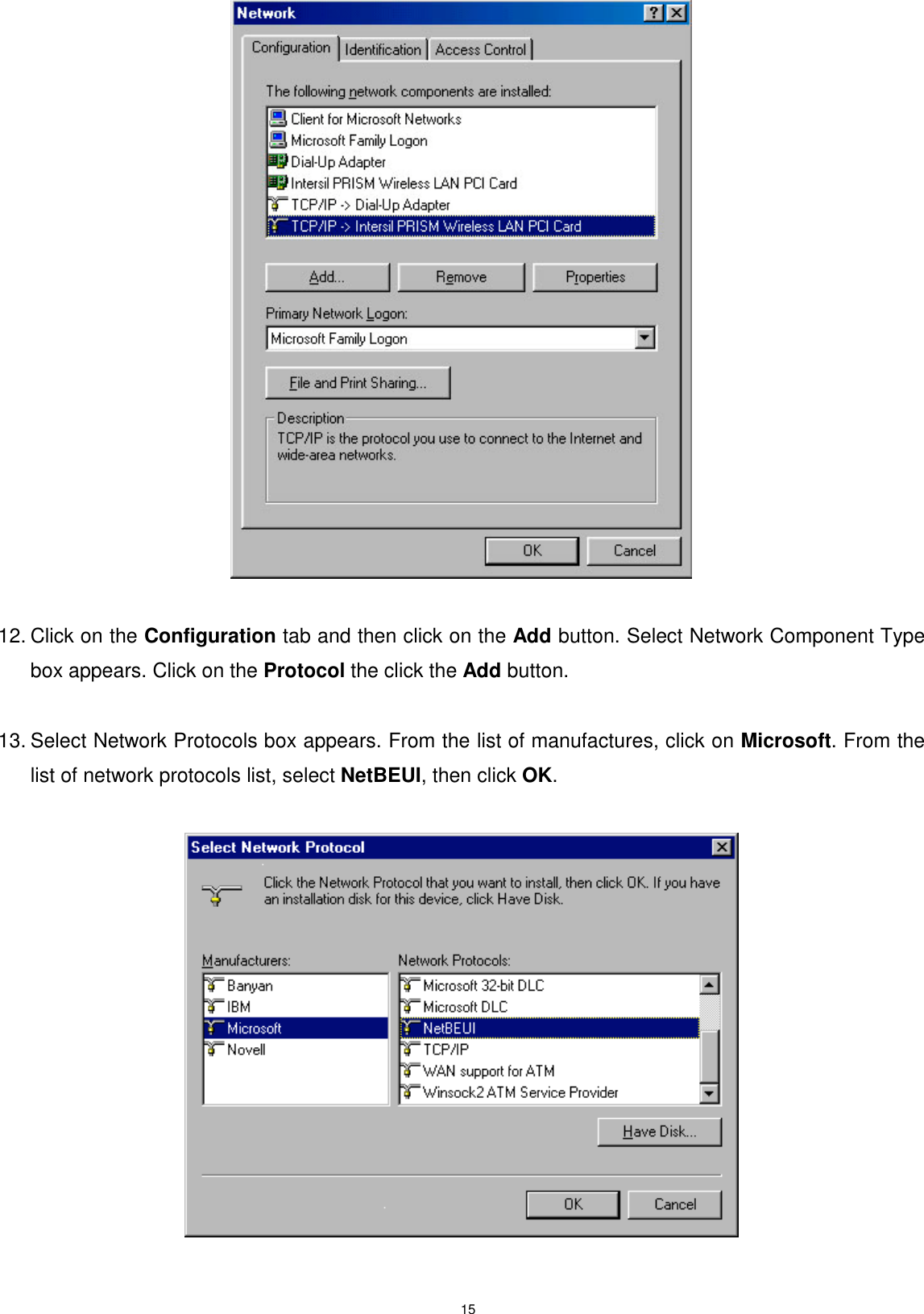
Upload a User Manual
Namespaces
Wiki Guide
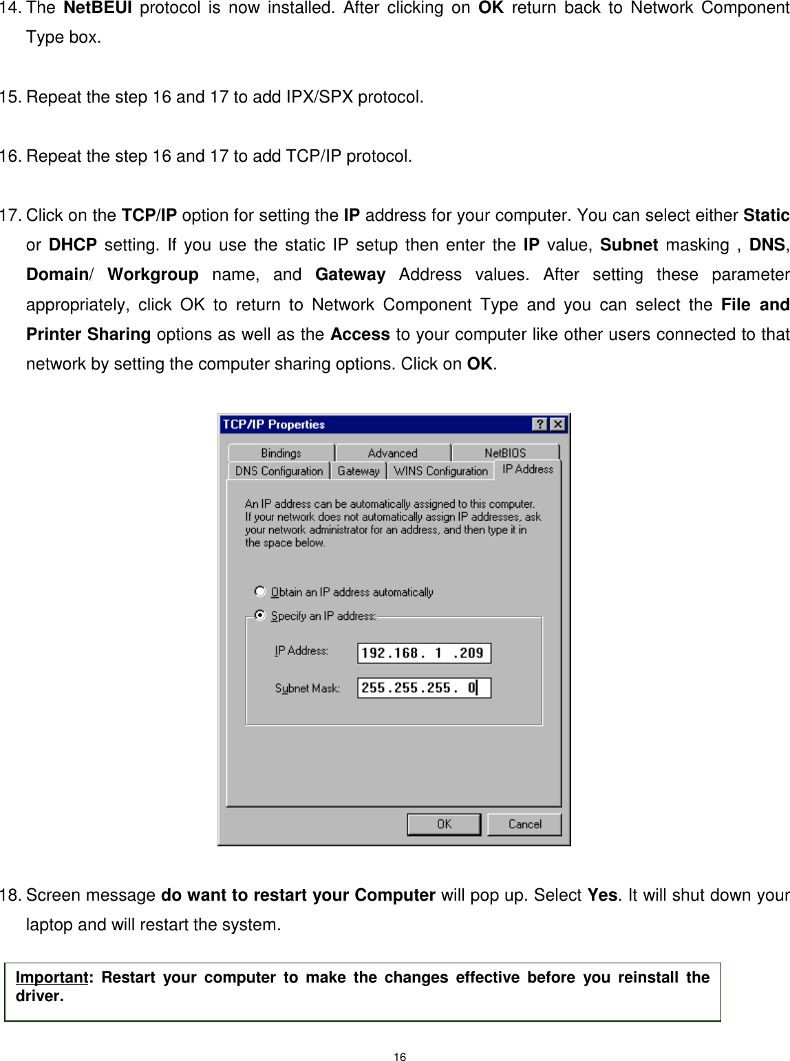
HTML
PDF
Info
Views
User Manual
Discussion / Help
Navigation