GemTek Technology R900621 2.4GHz Wireless Router User Manual Manual

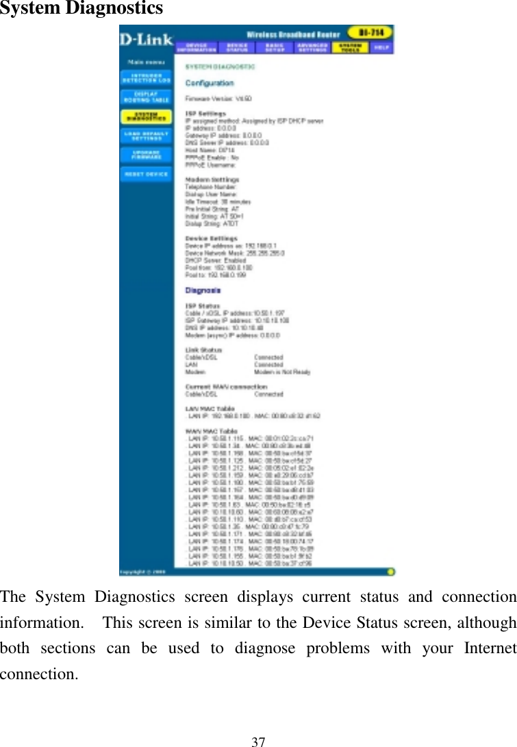
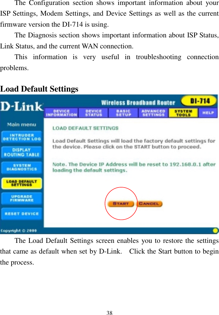
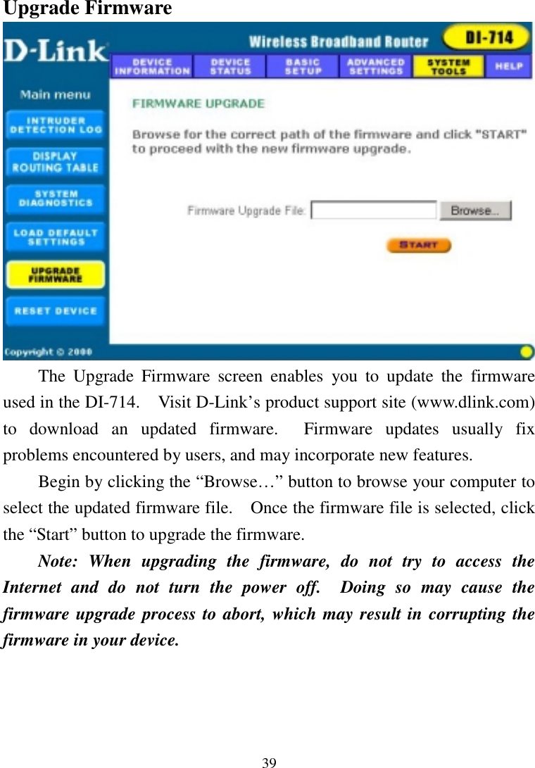
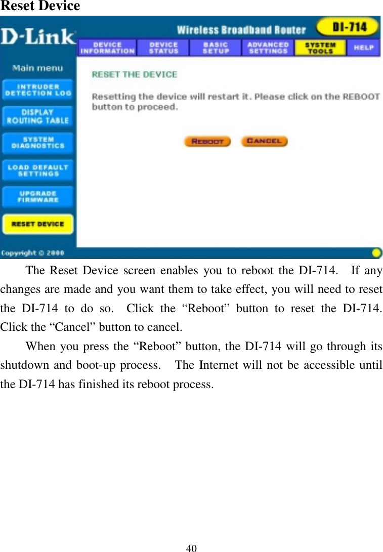
Gemtek Technology Co., Ltd. 2.4GHz Wireless Router Manual

Manual

D-LinkDI-714WirelessBroadband RouterUser’s Manual                                               Rev. 10022001
2ContentsIntroduction................................................................................................ 5Package Contents..................................................................................... 6Introduction to Broadband Router Technology ....................................... 7Introduction to Firewalls.......................................................................... 7Introduction to Local Area Networking................................................... 8Introduction to Virtual Private Networking............................................. 9Introduction to Wireless Networking..................................................... 10Hardware Installation ............................................................................. 12Placement............................................................................................... 12Safety Precautions ................................................................................. 12Side Panel .............................................................................................. 13Front Panel............................................................................................. 13Dail-Up .............................................................................................. 13Local Ethernet.................................................................................... 13Rear Panel.............................................................................................. 13Dial-Up Modem................................................................................. 13 Basic DI-714 Configuration & Main Page............................................. 14Start-up and Log in ................................................................................ 14Main Page.............................................................................................. 16Setup Wizard.......................................................................................... 16Time Settings ..................................................................................... 17Device IP Settings.............................................................................. 18Cable/DSL ISP Settings..................................................................... 19ISP Additional Settings...................................................................... 20Modem Settings ................................................................................. 22Device Information................................................................................ 23
3Device Status ......................................................................................... 24Basic Setup ............................................................................................ 25Advanced Settings.................................................................................... 27DHCP Server Settings............................................................................ 27Virtual Server Settings........................................................................... 28DMZ................................................................................................... 29Static Routing ........................................................................................ 30Dynamic Settings................................................................................... 31Modem String Settings .......................................................................... 32Password Settings .................................................................................. 33System Tools ............................................................................................. 34Intruder Detection Log .......................................................................... 34Display Routing Table ........................................................................... 35System Diagnostics................................................................................ 37Load Default Settings ............................................................................ 38Upgrade Firmware ................................................................................. 39Reset Device .......................................................................................... 40Troubleshooting ....................................................................................... 41Basic Functions...................................................................................... 41LAN Connection Problems.................................................................... 43ISP Connection Problems ...................................................................... 45Internet Application Problems ............................................................... 46Wireless Troubleshooting ...................................................................... 47Performing a Factory Reset ................................................................... 48Using the PING Utility in Windows 95/98/Me ..................................... 49Using the WINIPCFG Utility in Windows 95/98/Me ........................... 51Technical Specifications........................................................................... 53Contacting Technical Support ................................................................ 54
4D-Link Offices.......................................................................................... 55Limited Warranty.................................................................................... 56Registration Card............................................................................... 65
5IntroductionCongratulations on your purchase of the D-Link Wireless BroadbandRouter.    Your Wireless Broadband Router enables you to share your DSLor Cable Internet connection with computers on your network.    This guidewill explain the features and functions of the Wireless Broadband Router tohelp you get the most out of your Internet experience.D-Link’s DI-714 allows LAN users to share a single InternetConnection while providing the safety and security of port blocking,packet filtering, and a natural firewall.    Static address support, integratedDHCP, PPPoE, and device name support will allow it to connect to nearlyany broadband provider whether Cable or DSL based, and at the same timesimplify local area network settings.The DI-714 provides two levels of security support.   First, it maskslocal users’ IP addresses from others on the Internet making it much moredifficult for a hacker to target a machine on your network.  Secondly, itcan block and redirect certain ports to limit the services that outside userscan access.    Specific ports can be opened to ensure that games and otherInternet applications will run properly.The Wireless Broadband Router provides special pass-throughsupport for common VPN implementations.   The Virtual Server featureallows you to expose HTTP, FTP, Game Servers and other local services tobe accessible to Internet users located outside of the LAN.   The User-Definable Application Sensing Tunnel feature allows you to define theattributes to support special applications requiring multiple connections,such as Internet gaming, video conferencing, and Internet telephony.   ADMZ setting can be applied to a single client behind the Wireless
6Broadband Router to expose it to the Internet and ensure complete Internetapplication compatibility even if specific ports are not known.Unlike proxy server or NAT software that requires the software serverto remain visible on the Internet, local networked computers are notdirectly externally visible when using the DI-714.  Also the WirelessBroadband Router, like broadband, is always on, removing the need toconstantly boot a software server when access is desired from a client.Integrated DHCP services allow up to 253 users to get their IP addressautomatically on boot up from the DI-714.  Client machines require nosoftware (only the installed NIC card in a wireless network), simply set theEthernet or wireless adapters to accept a dynamically assigned IP addressand reboot.  Each time they are powered up the DI-714 will recognizethem and set their IP address to instantly connect them to the LAN.Package ContentsThe D-Link DI-714 package should include the following items. DI-714 Wireless Broadband router User’s Manual Quick Install Guide Power Adapter CAT-5 UTP Cable
7Introduction to Broadband Router TechnologyA router is a device that forwards data packets from a source to adestination.  Routers work on the OSI (Open System Interconnection)Layer 3, which forwards data packets using IP addresses and not a MAC(Media Access Control) address.   A router will forward data from theInternet to a particular computer on your LAN.The information that makes up the Internet gets moved around usingrouters.    When you click on a link on a web page, you send a request to aserver to show you the next page.  The information that is sent andreceived from your computer is moved from your computer to the serverusing routers.  A router also determines the best route that yourinformation should follow to ensure that the information is deliveredproperly.A router controls the amount of data that is sent through your networkby eliminating information that should not be there.  This providessecurity for the computers behind your router because computers from theoutside cannot access or send information directly to any computer on yournetwork.   The router determines which computer the information shouldbe forwarded to and sends it.    If the information is not intended for anycomputer on your network, the data is discarded.  This keeps anyunwanted or harmful information from accessing or damaging yournetwork.Introduction to FirewallsA firewall is a device that sits between your computer and the Internetthat prevents unauthorized access to or from your network.    A firewall canbe a computer using firewall software or a special piece of hardware built
8specifically to act as a firewall.    In most circumstances, a firewall is usedto prevent unauthorized Internet users from accessing private networkssuch as corporate LAN’s and Intranets.A firewall watches all of the information moving to and from yournetwork and analyzes each piece of data.    Each piece of data is checkedagainst a set of criteria that the administrator configures.    If any data doesnot meet the criteria, that data is blocked and discarded.    If the data meetsthe criteria, the data is passed through.   This method is called packetfiltering.A firewall can also run specific security functions based on the type ofapplication or type of port that is being used.    For example, a firewall canbe configured to work with an FTP or Telnet server.    Or a firewall can beconfigured to work with specific UDP or TCP ports to allow certainapplications or games to work properly over the Internet.Introduction to Local Area NetworkingLocal Area Networking (LAN) is the term used when connectingseveral computers together over a small area such as a building or group ofbuildings.  LAN’s can be connected over a large area.   A collection ofLAN’s connected over a large area is called a Wide Area Network (WAN).A LAN consists of multiple computers connected to each other.There are many types of media that can connect computers together.    Themost common media is CAT5 (Ethernet) cable; UTP or STP twisted pairwire.  On the other hand, wireless networks do not use wires; instead theycommunicate over radio waves.  Each computer must have a NetworkInterface Card (NIC), which communicates the data between computers.A NIC is usually a 10Mbps network card, or 10/100Mbps network card, or
9a wireless network card.Most networks use hardware devices such as hubs or switches thateach cable can be connected to in order to continue the connection betweencomputers.   A hub simply takes any data arriving through each port andforwards the data to all other ports.    A switch is more sophisticated, in thata switch can determine the destination port for a specific piece of data.    Aswitch minimizes network traffic overhead and speeds up thecommunication over a network.Networks take some time in order to plan and implement correctly.There are many types of scenarios to consider which could affect theoperability of a network.Introduction to Virtual Private NetworkingVirtual Private Networking (VPN) uses a publicly wired network (theInternet) to securely connect two different networks as if they were thesame network.  For example, an employee can access the corporatenetwork from home using VPN, allowing the employee to access files andprinters.  Here are several different implementations of VPN that can beused.Point-to-Point Tunneling Protocol (PPTP)PPTP uses proprietary means of connecting two private networks over theInternet.    PPTP is a way of securing the information that is communicatedbetween networks.  PPTP secures information by encrypting the datainside of a data packet.
10IP Security (IPSec)IPSec provides a more secure network-to-network connection across theInternet or a Wide Area Network (WAN).  IPSec encrypts allcommunication between the client and server whereas PPTP only encryptsthe data packets.Both of these VPN implementations are used because there is not astandard for VPN server software.    Because of this, each ISP or businesscan implement its own VPN network making interoperability a challenge.Introduction to Wireless NetworkingD-Link wireless products are based on industry standards to provideeasy- to- use and compatible high-speed wireless connectivity within yourhome or business.  Strictly adhering to IEEE 802.11b the D-Link Airwireless family of products will allow you to access the data you want,when and where you want it.  No longer will you be tethered to aworkstation or forced to run new wiring. You will be able to enjoy thefreedom that wireless networking delivers.Standards Based TechnologyBased on IEEE 802.11b, D-Link Air wireless products can throughputdata up to 11 Megabits per second.  This means you will be able totransfer large files quickly or even watch a movie in MPEG format overyour network without noticeable delays.    This technology works by usingmultiple frequencies in the 2.4GHz range utilizing Direct Sequence SpreadSpectrum (DSSS) technology.  D-Link Air products will automaticallysense the best possible connection speed to ensure the greatest speed andrange possible with the technology.
11Installation ConsiderationsDesigned to go up to 300 feet indoors and up to 900 feet outdoors, D-Link Air lets you access your network from virtually anywhere you want.Keep in mind, however, that the number of walls, ceilings or other objectsthat the wireless signals must pass thru will limit range.   Typical rangesvary depending on the types of materials and background RF noise may beevident in your home or business.   The key to maximizing range is tofollow these basic principles:1.  Keep the number of walls and ceilings to a minimum - Each wall orceiling can reduce your D-Link Air Wireless products range from 3-90feet.    Position your Access Points(base stations in a wireless network),Routers, and Computers so that the number of walls or ceilings isminimized.2.  Be aware of the direct line between Access Points, Wireless BroadbandRouters, and Computers - A wall that is 1 foot thick, at a 45 degreeangle appears to be almost 3 feet thick.    At a 2 degree angle it looksover 42 feet thick!   Try to make sure that the AP and Adapters arepositioned so that the signal will travel straight through a wall orceiling for better reception.3.  Building Materials make a difference - A solid metal door or aluminumstuds may have a negative effect on range.   Again, try to positionAccess Points, Routers, and Computers so that the signal passesthrough drywall or open doorways and not other materials.4.  Make sure that the antenna is positioned for best reception by using thesoftware signal strength tools included with your product.5. Keep your product at least 3-6 feet away from electrical devices thatgenerate RF noise, like microwaves, Monitors, electric motors, etc.
12For the average American multiple bedroom home, range should not be aproblem.  If you experience low or no signal strength in areas of yourhome that you wish to access, consider positioning the Access Point in alocation directly between the Routers and/or Computers that will beconnected.   Additional Access Points can be connected to provide bettercoverage in rooms where the signal does not appear as strong as desired.Hardware InstallationPlacementThe DI-714 Wireless Broadband Router should be placed in a safe andsecure location. To ensure proper operation, please keep the unit awayfrom water and other damaging elements.Safety Precautions Please read the installation guide thoroughly before you install the DI-714. The DI-714 should only be repaired by authorized and qualifiedpersonnel. Please do not try to open or repair the DI-714 yourself.    Opening thedevice will violate the products warranty. Do not place the DI-714 in a damp or humid location, e.g. a bathroom. The DI-714 should be placed in a sheltered and non-slip locationwithin a temperature range of 41 to 104 degrees Fahrenheit. Please keep the plastic bag of the DI-714 and the clip binding the cableout of reach of children and babies to avoid choking. Please do not expose the DI-714 to direct sunlight or other heat      sources. The device’s housing and internal electronic components      may be damaged by direct sunlight or heat sources.
13Side PanelThe power port is located on the right-hand side of the DI-714.    Connectthe AC adapter to this port to supply power.Front PanelThe front panel provides LED’s to indicate the device’s status.    Refer tothe following table for the meaning of each feature.Power Power status of the DI-714.    A steady LED indicates thatthe power is on.    No LED lights indicate lack of power.Status Router status indicates. When router boot or Flash memorywriting Status LED should be blinking.Broadband Wide Area Network status.    When connected to theCable/DSL modem, the LED should be on.Dial-Up Indicates Dial-UP Modem port their Carrier Detect status.When modem connection is established then LED should besteady on.Wireless Indicates wireless initial ready status. When wireless APinitial ready, the LED should be steady on.LocalEthernet1,2,3,4Link/ACT = Displays Link Activity.When each of LAN port connects to PC or HUB, Link/ACTshould be steady on, when data transfer then Link/ACTshould be blinking.Rear PanelThe rear panel features a LAN port, WAN port ( BroadBand) ,SerialModem port and Factory Reset button. Refer to the following table for themeaning of each feature.5V  DC Used to connect to the power outlet. Only use the poweradapter provided with the DI-714. Use of anunauthorized power adapter may cause damage to yourdevice and violate your warranty.BROADBAND The RJ-45 Ethernet port labeled BroadBand is used toconnect your DI-714 to your xDSL or Cable modem.
14DIAL-UPMODEM Port used to connect an external analog backupmodem/ISDN TA.RESET Resets the configuration to default settings.Local Ethernet1 ,  2,  3,  4 The RJ-45 Ethernet ports used to connect your PC orHUB , The Ethernet Cable used can be normal Ethernetcables or even Crossover Cable.The 714 have internal AutoCrossover detection circuit toautomatic identify    them.Basic DI-714 Configuration & Main PageThe DI-714 provides a Web Configuration interface that can beaccessed using standard web browsers such as Netscape Communicator orMicrosoft Internet Explorer.    Since the interface is web based (HTTP), theDI-714 can be configured with any Java and HTML compliant Internetbrowser in any operating system.  This section will discuss the WebConfiguration interface and how to use different options and settings.Although you can change the IP address of the DI-714 to meet yourneeds, this manual will assume that the defaults are left in place.   Thismeans that the IP address of your DI-714 will be 192.168.0.1.    If you havechanged the IP address scheme, please substitute 192.168.0.1 with the IPaddress scheme that you have chosen.Start-up and Log inIn order to configure the DI-714, you must use your web browser andmanually input 192.168.0.1 into the Address box and press Enter.   TheMain Page will appear.  The Device Information and Device Statusscreens can be seen without logging into the DI-714.    However, when theSetup Wizard, Basic Setup, Advanced Settings and System Tools buttons
15are pressed, the log in screen will be shown.In order to configure the DI-714 you must input the user-name intothe  User Name box.  Enter the password into the Password box andpress the OK button.   The default User Name is “admin.”    There is nodefault password, leave the Password field blank.Once you have logged-in as administrator, it is a good idea to changethe administrator password to ensure a secure connection to the DI-714.The Advanced Settings section described later in this manual describeshow to change the password.Once you have input the correct password and logged-in, the screenwill change to the Main Page screen.If you are having problems logging in and you are sure that thepassword you are using is correct, check the top right-hand corner of yourkeyboard to make sure that the Caps Lock light is not on.
16Main PageThe Main Page screen provides links to the main sections of the webconfiguration interface.Setup WizardThe Setup Wizard is a step-by-step guide to configuring the DI-714 towork with your ISP provider.    Please refer to the Quick Install Guide foradditional instructions.
17Time SettingsPlease choose the local time zone.    After selecting the correct time zone,click on the Next button to continue.    You can also click the buttons onthe left hand side to reach a specific setting in the configuration.
18Device IP SettingsYou have to give your Internet gateway an IP address on your “private”network.    This is not the “public” IP address from your ISP but the localinternal LAN IP address.    The IP address of “192.168.0.1” is the defaultIP address of the LAN port in the broadband router.Device IP AddressThe internal LAN IP address of the broadband router.Device IP Subnet MaskThe subnet mask can usually be left with the default entry of“255.255.255.0”
19Cable/DSL ISP SettingsThe DSL/Cable ISP settings have a default to obtain dynamically the IPaddress for the WAN port of the broadband router.    Some ISPs may giveyou Static IP settings.    If this is the case for your ISP then you need to:Enter the IP address that is assigned by your ISPEnter the IP subnet maskEnter the ISP gateway addressEnter the DNS IP address
20ISP Additional SettingsIf you would like to use ISP additional settings you have to enable thisfunction and configure this page.  Some ISPs use this protocol forauthentication purposes; if this is the case, you need to enter:User name: Enter the user name of your ISP account.Password: Enter the password of your ISP account.Retype password: Enter the password of your ISP account again to re-confirm.
21Some ISPs, especially cable modem providers, use the “Host Name” toauthenticate the user.    If this is the case, you will need to enter:Host Name: Enter the host name provided by the ISP.Some ISPs require the user to input the MAC address of the originalEthernet adapter.    If this is the case, enter:MAC Address: Enter the MAC address of the Ethernet adapter.Some ISPs may recognize your LAN card MAC address as a legal user;In this case, you have to copy the LAN card MAC address in the MAC address field.For WIN 95/98 you can run winipcfg to see the LAN card MAC addressFor WIN 2000/NT you can run ipconfig /all to see the LAN card MAC addressNOTE !
22Modem SettingsAn analog external modem can be used as a dialup backup to theDSL/Cable connection.  If you would like to use a modem backup, youneed to enable the modem settings function.    Click on “Modem Settings”on the left hand side and input the ISP account settings.Note: If you change the baud rate settings, please check the initial string.(Please refer to the modem’s manual.)
23Device InformationThe Device Information screen displays the basic information of yourDI-714. The Device Name is the same as the Computer Name that was setin the Setup Wizard.The IP Address is the IP Address assigned to LAN side of your DI-714.The Private LAN MAC Address the MAC Address assigned to theLAN side of your DI-714.The Public WAN (Cable/DSL) MAC Address is the MAC Addressassigned to the WAN port of the DI-714.   This MAC Address may beused by some cable modem connections.    The Firmware Version is thecurrent firmware version used by the DI-714.
24Device StatusThe Device Status screen displays a graphical representation of yourcurrent configuration. The left side of the screen shows your connectioninformation in regards to WAN and LAN IP Address information.   Theright side displays the connection status of each device. This means that there is a connection. This means that there is not a connection.
25The DHCP Log displays information about each IP Address assignedto a computer using the DHCP server built-in to the DI-714.Basic SetupThe Basic Setup screen enables you to change basic settings related toaccessing the Internet.   All of the settings covered in the Basic Setupsection are covered in the Setup Wizard.The Computer Name is used to give a name to your connection ifyou are using a Cable modem.The Domain Name (host name) is the name given to you by your ISPprovider if you using the @Home cable Internet service.Choose the Type of Connection you use by selecting Dynamic IP,Static IP, or PPPoE.
26Select Dynamic IP if your ISP has not given you a unique IP addressand you receive an automatic IP address each time you connect to your ISP.The rest of the settings related to your connection are retrievedautomatically each time you connect to the Internet.Select Static IP if your ISP assigns you an IP address. This means thatyour ISP has given you an IP address that you will use to connect to theInternet through their service.  If you select Static IP, you will need toenter the correct values for the IP Address, Subnet Mask and Gateway inthe fields provided.Select  PPPoE if your ISP uses the Point-to-Point over Ethernetprotocol to authenticate a username and password and then automaticallyassign you an IP Address.    PPP over Ethernet (PPPoE) is a non-standardmethod of connecting to your ISP to obtain an IP address.    It relies upon asoftware client that is provided by the ISP.  If you have a broadbandconnection and login to your ISP like you would do with a dial-in modem,then you are probably using PPPoE.    If you are simply connected to theInternet when you turn on your computer, you probably are not.   Thesafest way to check is to call your ISP or read the documentation providedwhen you signed up for your Internet service.   If you select PPPoE, youwill need to enter the correct values for your User Name and Password inthe fields provided.    The DNS section needs to be set to the correct optionin order for the DI-714 to resolve domain name information in URL’s.Select Dynamic DNS if your ISP provides the DNS information muchin the same way as you receive an IP Address.Select  Static DNS if you were given the DNS server informationwhen you signed with your ISP.    Click on the Save & Restart button tosave your settings.
27Advanced SettingsDHCP Server SettingsBy default, the Broadband Router has DHCP server enabled to assign an IPaddress ranging from 192.168.0.100 to 192.168.0.199.  In addition, therouter is capable of reserving up to four IP addresses within the localnetwork for mail, web, or ftp server.
28Virtual Server SettingsSpecific application support is enabled in Virtual Server Settingsunder Advanced Settings.  Click on the arrow to select the commonapplications such as FTP, Web server, and mail server. The DI-714Broadband Router will detect and automatically open outgoing portsrequired by most applications and games.  However, some games andapplications such as MSNetmeeting will require that the computer beexposed in the DMZ zone to allow incoming ports required by theapplication.    Click on the “Submit” button to save your settings.
29DMZThe Virtual Server Settings under Advanced Settings also enables onecomputer to have full access to the Internet without the protection of thefirewall. This allows a computer to be exposed to unrestricted two-waycommunication outside of your network.To enable DMZ, click the checkbox to the left and select “All”. Thentype the IP address of the selected computer in the box provided.   Clickthe “Submit” button to save your changes.Only one computer can use DMZ at a time. Please note thatenabling DMZ removes the protection of the firewall, which exposesthe computer to intrusion.Use DMZ only when needed and not for extended periods of time.In some circumstances with gaming, enabling DMZ may help thegame contact the maximum number of servers, which can improve pingtimes. Once the game connects to the game server, disable DMZ to ensureproper firewall protection.
30Static RoutingIn Static Routing, the user has the ability to add a static route to therouting table by simple entering the destination IP, subnet mask, andgateway.    Clicking on “Add” and then “Submit” which requires a restartfor the IP address to be incorporated into the routing table.
31Dynamic SettingsBy default, the Broadband Router will not send or receive any routingInternet protocols (RIP) to update the routing table.  However, the usercan enable the Broadband Router to automatically send and receive RIPpackets to establish routes for commonly used paths.
32Modem String SettingsMost dial-up modems are compatible with the standard modemstrings.  However for modems that require special modem strings, theuser can enter the information in this screen.
33Password SettingsYou can give your Internet gateway a new password.    This password willbe required the next time and subsequent times you configure your Internetgateway.    To enter a password, type your password in the new passwordfield and type it again in the retype password field.Note: It is important to remember your password.    If for any reason youlose or forget your password, there is a small reset button located on theback of the device.    Pressing this button for 3 seconds will not only resetthe password, but also the device itself—and all previous configurationswill need to be input again.
34System ToolsThe System Tools section enables you to manage your DI-714 andview information related to unit functions.   The following functions aredescribed in this chapter.Intruder Detection Log: View detection logs.Display Routing Table: View routing table list.System Diagnostics: Change remote configuration settings.Load Default Settings: Restore settings to factory default.Upgrade Firmware: Upgrade the firmware to a newer version.Reset Device: Reboot the DI-714.Intruder Detection LogThe Intruder Detection Log displays all information related to intrusion
35attempts on your network.  If any packets are seen as harmful, thosepackets are blocked and a log is kept about the information related to thatpacket.Index: (1,2,3 etc.) Refers to the row number.Time: The time that the action was logged.Protocol: (IP, UDP etc.) The type of protocol detected.Source IP (Port): The source IP address of the intruding packet.Dest IP (Port): The IP address assigned to the destination of theintruding packet.Event: The type of intrusion.Display Routing TableThe Display Routing Table screen displays the routing table that the DI-714 is using.   A router uses a routing table to keep track of what IP
36addresses there are and where the router should forward packets when itreceives them.Type: The type of routing protocol used.Destination LAN IP Address: Shows the Destination IP Address onthe LAN side.Subnet Mask: Shows the subnet mask assigned to the DestinationLAN IP Address.Gateway IP Address: The IP Address of the assigned Gateway.Hop Count: The number of hops between the Destination LAN IPAddress and the Gateway IP Address.
37System DiagnosticsThe System Diagnostics screen displays current status and connectioninformation.    This screen is similar to the Device Status screen, althoughboth sections can be used to diagnose problems with your Internetconnection.
38The Configuration section shows important information about yourISP Settings, Modem Settings, and Device Settings as well as the currentfirmware version the DI-714 is using.The Diagnosis section shows important information about ISP Status,Link Status, and the current WAN connection.This information is very useful in troubleshooting connectionproblems.Load Default SettingsThe Load Default Settings screen enables you to restore the settingsthat came as default when set by D-Link.    Click the Start button to beginthe process.
39Upgrade FirmwareThe Upgrade Firmware screen enables you to update the firmwareused in the DI-714.    Visit D-Link’s product support site (www.dlink.com)to download an updated firmware.  Firmware updates usually fixproblems encountered by users, and may incorporate new features.Begin by clicking the “Browse…” button to browse your computer toselect the updated firmware file.    Once the firmware file is selected, clickthe “Start” button to upgrade the firmware.Note: When upgrading the firmware, do not try to access theInternet and do not turn the power off.  Doing so may cause thefirmware upgrade process to abort, which may result in corrupting thefirmware in your device.
40Reset DeviceThe Reset Device screen enables you to reboot the DI-714.  If anychanges are made and you want them to take effect, you will need to resetthe DI-714 to do so.  Click the “Reboot” button to reset the DI-714.Click the “Cancel” button to cancel.When you press the “Reboot” button, the DI-714 will go through itsshutdown and boot-up process.   The Internet will not be accessible untilthe DI-714 has finished its reboot process.
41TroubleshootingIn the event that you are unable to connect to or use your DI-714Wireless Broadband Router, please refer to the following troubleshootingguide. After each problem description, a possible cause and problemresolution is provided. If this section does not help you fix the problem, goto the D-Link web site (www.dlink.com) for additional troubleshooting tips.If neither of these helps, please contact D-Link Technical Support foradditional help. The phone numbers for Technical Support are in theappendix of this manual under D-Link Office Information.Basic FunctionsMy Broadband Router will not turn on. No LED’s light up.Cause: The power is not connected or the power switch is set to “Off”.Resolution: Connect the power adapter to your Broadband Router and plug it intothe power outlet. Make sure that the power switch is set to “On”.Note: Only use the power adapter provided with your Broadband Router.Using any other adapter may damage your Broadband Router and violateyour warranty.
42LED’s don’t follow the correct boot-up sequence as stated in the QuickInstall Guide.Cause: The unit’s firmware is corrupt. The unit is not receiving the correct voltage from the power supply.Resolution: Download and upgrade the latest firmware. Make sure the correct firmware has been used while upgrading. Useonly the firmware provided on D-Link’s web or FTP sites. Use only the power adapter provided.The Link or Act LED’s do not turn on.Cause: The network cable is not connected. The network cable is connected but not the right type, whether it ispatch or straight-through.Resolution: Make sure that both ends of the cable are connected. Try using another cable. If you are using a straight-through cable, try a patch cable and vice-versa.Sometimes my Broadband Router stops working or locks up.Cause: Someone has attempted to hack into someone on your LAN. The Broadband Router has detected harmful data trying to access yourLAN.
43 The NAT table is full.Resolution: Reboot the Broadband Router by turning the power to the unit off andthen on again. Some types of hacker tools use very non-standard datastreams. Some of these streams may cause the Broadband Router tolock up.    When the Broadband Router locks up, it will not affect thecomputers attached to it.    You may need to restart the client computersto regain Internet access.Although sometimes inconvenient, a lock-up is an indication of anattack.    Part of the design of the Broadband Router is to act as a decoyfor such traffic.    If your computer is locked up instead you may havelost changes to open, unsaved files, lost data, or corrupted youroperating system or hard drive.If you are currently experiencing frequent lock-ups, you may wish toupgrade the firmware.LAN Connection ProblemsI can’t access my Broadband Router.Cause: The unit is not turned on. There is not a network connection. The computer you are using does not have a compatible IP Address.Resolution: Make sure your Broadband Router is turned on. Make sure that there is a physical connection between your computerand the Broadband Router and that the Link light is on.
44 Use the WINIPCFG utility described in the appendix to make sure thatyour computer has a compatible IP Address. If your IP Address is notset correctly and you are using DHCP, use WINIPCFG to renew yourIP Address. Otherwise, make correct changes to your Windowsnetwork settings. Make sure that the IP Address used on your computeris set to the same subnet as the Broadband Router. For example, if theBroadband Router is set to 192.168.0.1, change the IP address of yourcomputer to 192.168.0.15 or another unique IP Address thatcorresponds to the 192.168.0.X subnet. Use the Reset button located on the front of your Broadband Router torevert to the default settings.I can’t connect to other computers on my LAN.Cause: The IP Addresses of the computers are not set correctly. Network cables are not connected properly. Windows network settings are not set correctly.Resolution: Make sure that each computer has a unique IP Address. If using DHCPthrough the Broadband Router, make sure that each computer is set to“Obtain an IP Address automatically” and restart the computer. Use theWINIPCFG and PING utilities described in the appendix to make surethat you can connect to each computer. Make sure that the Link LED is on. If it is not, try a different networkcable. Check each computer for correct network settings.
45ISP Connection ProblemsI can access the Broadband Router, but I can’t connect to my ISP.Cause: Your DSL or Cable modem is not functioning correctly. The cable is connected from the WAN port of the Broadband Router toyour DSL or Cable modem. The wrong connection type is used in Setup. The username and password is not input correctly. If using @Home service, the computer name is not input correctly. Your ISP may only allow one MAC address to access the Internet. You ISP may only allow one computer to access their service.Resolution: Make sure that your DSL or Cable modem is running correctly andconnected to the WAN port of the Broadband Router. Make sure that the right connection type is used in the webconfiguration. Make sure that the username and password used in the connection typeis correct. If using @Home, make sure that the computer name is input correctly. Clone the MAC address using the web configuration interface. Some ISP's do not care if you share your broadband connection amongmultiple users. Other ISP's will explicitly restrict this type of activity inyour service contract. It is important that you verify that you are inaccordance with your service agreement before sharing Internet access.
46Internet Application ProblemsMy online game does not work.Cause: The NAT table has filled up. The correct settings have not been used to open the correct ports foryour application. The unit has stopped working or crashed.Resolution: If you are trying to connect to game servers and your connection hasstopped working, wait a few minutes or turn the unit off and then onagain. Games send out many requests to many different servers tryingto find the best game server for your connection. When this is done, theNAT table used in the Broadband Router can fill up and stop workingtemporarily. Try using the DMZ host feature while connecting to gameservers and then disabling DMZ while playing the game. Turn the Broadband Router off and then on again to reset the NATtable. Make sure that the correct ports have been opened in order for yourspecific game to operate correctly behind a firewall. Consult your gamedocumentation or contact the technical support of the game company toobtain the correct settings for your game. Some games just won’t operate correctly behind a firewall. In this case,use the DMZ host feature while using the game, then turning DMZ offwhile the game is not being played to ensure proper firewall protection.
47My E-Mail program doesn’t receive my E-MailCause: The Domain Suffix is not set correctly.Resolution: Some email applications require you to enter the Domain Suffix whenyou configure your network and TCP/IP settings. The Domain Suffix isthe unique identifier for your email server. The Domain Suffix is the Internet Protocol (TCP/IP) address of theemail server you are using. Your cable modem or DSL provider usuallylists it somewhere on your invoice. The Domain Suffix address shouldappear similar to this: dlink.occa.home.com. Find the Domain Suffixon your invoice or call your Internet Service Provider (ISP) to obtain it.Wireless TroubleshootingCan’t access the Broadband Router from a wireless network cardCause: Settings are not the same among each wireless adapter. Out of range. IP Address is not set correctly.Resolution: Make sure that the Mode, SSID, Channel and encryption settings areset the same on each wireless adapter. The default SSID and Channelthat the Wireless Broadband Router uses is “default” and “6”respectively. Make sure that your computer is within range and free from any strongelectrical devices that may cause interference. Refer to the section
48“Introduction to Wireless Networking” for tips to help make a goodconnection. Check your IP Address to make sure that it is compatible with theWireless Broadband Router. The default IP Address of the WirelessBroadband Router is “192.168.0.1”. A compatible IP Address would be“192.168.0.50”Performing a Factory ResetTo perform a Factory Reset using the Reset button on the back of theDI-714 do the following:Press and hold the Reset button with a pen or paper clip for 3 seconds.A Factory Reset can also be performed through the web configurationinterface. Follow these steps to perform a factory reset using the webconfiguration interface.1. Log-in to the DI-714 web configuration interface.2. Click on the System Tools link at the bottom of the screen.3. Click on Load Default Settings.4. You will be asked if you want to restore to default settings. ClickOK to restore settings to default configuration or click Cancel.
49Using the PING Utility in Windows 95/98/MeIn Windows, Microsoft has provided a small utility called PING thatcan be used to troubleshoot your IP address and connection. The PINGutility is used mainly to test the connection between your computer and aclient computer. Using the PING utility to check a connection can behelpful in determining where the problem is, whether it be your BroadbandRouter, your DSL or Cable modem, or your ISP.Use the following steps to use the WINIPCFG utility: Click on the Start button and click Run. Type "command" in the Open box. Click "OK" to get to a DOS prompt. Type "ping 192.168.0.1", which is the IP address of the Router inthis case, and hit the Enter key. The following screen will beshown.C:\>ping 192.168.0.1Pinging 192.168.0.1 with 32 bytes of data:Reply from 192.168.0.1: bytes=32 time=130ms TTL=64Reply from 192.168.0.1: bytes=32 time=10ms TTL=64Reply from 192.168.0.1: bytes=32 time=20ms TTL=64Reply from 192.168.0.1: bytes=32 time=10ms TTL=64Ping statistics for 192.168.0.1:        Packets: Sent = 4, Received = 4, Lost = 0 (0% loss),Approximate round trip times in milli-seconds:    Minimum = 10ms, Maximum =  130ms, Average =  42msThis screen shows a successful connection between you and yourBroadband Router. You can use these same steps to ping your DSLor Cable modem and then your ISP provider and Internet website.If any one of these attempts results in an unsuccessful PING, your
50connection is not complete.If a PING is unsuccessful between you and your DSL or Cablemodem, then your connection is not setup correctly. If it isunsuccessful when PINGing your ISP or an Internet site, then yourconnection is setup correctly but there is a problem with your ISPor the Internet site you tried to PING is unavailable. The screen shown below is an example of an unsuccessful PING.C:\>ping 192.168.0.1Pinging 192.168.0.1 with 32 bytes of data:Request timed out.Request timed out.Request timed out.Request timed out.Ping statistics for 192.168.0.1:        Packets: Sent = 4, Received = 0, Lost = 4 (100% loss),Approximate round trip times in milli-seconds:    Minimum = 0ms, Maximum =  0ms, Average =  0ms
51Using the WINIPCFG Utility in Windows 95/98/MeIn Microsoft Windows versions 95 through Me, Microsoft hasprovided a small utility called WINIPCFG that can be used to troubleshootyour IP address and connection. The WINIPCFG utility is used mainly toview, release and renew your IP Address configuration. Windows NT(including Windows 2000) has a similar utility called IPCONFIG that canbe used to perform similar tasks.Use the following steps to use the WINIPCFG utility: Click on the Start button and click Run Type "winipcfg" in the Open box. Click OK. The IP Configuration screen will be displayed.The IP address will be displayed in the IP Address box. If you havemore than one network card, make sure that the network card thatyou are using is displayed in the white dropdown box.Make sure that the Default Gateway is the IP Address of yourBroadband router. If it is not, you will not be able to connect to theInternet. If you are using DHCP, click the Release and then theD-Link DFE-530TX PCI Fast Eth
52Renew buttons to receive the correct settings. If you manually setyour network settings, make sure that the IP Address of yourBroadband Router is set in the Gateway portion of the TCP/IPsettings in your network settings. Click on "More Info" to display additional IP information.The important settings to watch for in this screen are in the HostInformation box. Make sure that the DNS Servers box has thecorrect DNS information.Also check the DHCP server box to make sure that you areconnected to the right DHCP server.D-Link DFE-530TX PCI Fast E
53Technical SpecificationsStandards:• IEEE 802.3 10BASE-T Ethernet• IEEE 802.3u 100BASE-TX Fast Ethernet• ANSI/IEEE 802.3 NWay auto-negotiationProtocols Supported:• TCP• IP• NAT• UDP• PPPoE• DHCP (Client and Server)Management:• Web-BasedPorts:• LAN: NWay 10BASE-T/100BASE-TX Fast Ethernet• WAN: 10BASE-T• RS-232 (DB-9) ConsoleAdditional details are available at D-Link’s web site (www.dlink.com).
54Contacting Technical SupportD-Link provides free technical support for customers within the UnitedStates. U.S. customers can contact D-Link technical support through ourweb site, e-mail, or by phone.United States technical support is available Monday through Friday from6:00 a.m. to 6:00 p.m. (PST).Web: http://www.dlink.comEmail: support@dlink.comPhone: 949-788-0805 (option #4)If you are a customer residing outside of the United States, please referto the list of D-Link offices that is included in this manual.Thank you for purchasing this product. We like to receive feedback fromour customers concerning our products. Please take a moment to visit ourweb site. You can register your purchase on-line, learn more about thenewest networking products, and let us know the things your new networkhas empowered you to do.
55D-Link OfficesAUSTRALIA D-LINK AUSTRALASIAUnit 16, 390 Eastern Valley Way, Roseville, NSW 2069, AustraliaTEL: 61-2-9417-7100    FAX: 61-2-9417-1077TOLL FREE: 1800-177-100 (Australia), 0800-900900 (New Zealand)                              URL: www.dlink.com.au  E-MAIL: support@dlink.com.au, info@dlink.com.auCANADA D-LINK CANADA2180 Winston Park Drive, Oakville, Ontario L6H 5W1 CanadaTEL: 1-905-829-5033    FAX: 1-905-829-5095    BBS: 1-965-279-8732    FREE CALL: 1-800-354-6522URL: www.dlink.ca   E-MAIL: techsup@dlink.caCHILE D-LINK SOUTH AMERICAIsidora Goyenechea #2934 of.702, Las Condes, Santiago, Chile                              TEL: 56-2-232-3185  FAX: 56-2-2320923  URL: www.dlink.clCHINA D-LINK CHINA2F., Sigma Building, 49 Zhichun Road, Haidian District, 100080 Beijing, ChinaTEL: 86-10-88097777    FAX: 86-10-88096789URL: www.dlink.com.cnDENMARK D-LINK DENMARKNaverland 2, DK-2600 Glostrup, Copenhagen, DenmarkTEL:45-43-969040  FAX:45-43-424347  URL: www.dlink.dkE-MAIL: info@dlink.dkEGYPT D-LINK MIDDLE EAST7 Assem Ebn Sabet Street, Heliopolis Cairo, EgyptTEL: 202-2456176  FAX: 202-2456192  URL: www.dlink-me.comE-MAIL: support@dlink-me.comFRANCE D-LINK FRANCELe Florilege #2, Allee de la Fresnerie78330 Fontenay Le Fleury FranceTEL: 33-1-30238688  FAX: 33-1-3023-8689  URL: www.dlink-france.frE-MAIL: info@dlink-france.frGERMANY D-LINK GERMANYBachstrae 22, D-65830 Kriftel GermanyTEL: 49-(0)6192-97110    FAX: 49-(0)6192-9711-11    URL: www.dlink.de    BBS: 49-(0)6192-971199 (Analog) 49-(0)6192-971198 (ISDN)INFO LINE: 00800-7250-0000 (toll free)    HELP LINE: 00800-7250-4000 (toll free)REPAIR LINE: 00800-7250-8000INDIA D-LINK INDIAPlot No.5, Kurla-Bandra Complex Road,Off Cst Road, Santacruz (E), Bombay - 400 098 IndiaTEL: 91-22-652-6696    FAX: 91-22-652-8914    URL: www.dlink-india.comE-MAIL: service@dlink.india.comITALY D-LINK ITALIAVia Nino Bonnet No. 6/b, 20154 Milano, ItalyTEL: 39-02-2900-0676  FAX: 39-02-2900-1723    URL: www.dlink.itE-MAIL: info@dlink.itJAPAN D-LINK JAPAN10F, 8-8-15 Nishi-Gotanda, Shinagawa-ku, Tokyo 141 JapanTEL: 81-3-5434-9678    FAX: 81-3-5434-9868    URL: www.d-link.co.jp   RUSSIA D-LINK RUSSIAMichurinski Prospekt 49, 117607 Moscow, RussiaTEL: 7-095-737-3389, 7-095-737-3492   FAX: 7-095-737-3390   SINGAPORE D-LINK INTERNATIONAL1 International Business Park, #03-12 The Synergy, Singapore 609917TEL: 65-774-6233  FAX: 65-774-6322URL: www.dlink-intl.com  E-MAIL: info@dlink.com.sgS. AFRICA D-LINK SOUTH AFRICAUnit 2, Parkside 86 Oak AvenueHighveld Technopark Centurion, Gauteng, Republic of South AfricaTEL: 27(0)126652165    FAX: 27(0)126652186SWEDEN D-LINK SWEDENP.O. Box 15036, S-167 15 Bromma SwedenTEL: 46-(0)8564-61900    FAX: 46-(0)8564-61901    E-MAIL: info@dlink.seURL: www.dlink.seTAIWAN D-LINK TAIWAN2F, No. 119 Pao-Chung Road, Hsin-Tien, Taipei, Taiwan, R.O.C.TEL: 886-2-2910-2626  FAX: 886-2-2910-1515  URL: www.dlinktw.com.twU.K. D-LINK EUROPE4th Floor, Merit House, Edgware Road, Colindale, London,    NW9 5AB, U.K.TEL: 44-20-8731-5555    FAX: 44-20-8731-5511URL: www.dlink.co.uk  E-MAIL: info@dlink.co.ukU.S.A. D-LINK U.S.A.53 Discovery Drive, Irvine, CA 92618    USATEL: 1-949-788-0805    FAX: 1-949-753-7033    INFO LINE: 1-800-326-1688BBS: 1-949-455-1779, 1-949-455-9616URL: www.dlink.com  E-MAIL: tech@dlink.com, support@dlink.comTech Support Hours: 6 A.M. to 6 P.M. Pacific Standard Time. Monday through Friday
56Limited WarrantyD-Link Systems, Inc. (“D-Link”) provides this limited warranty for itsproduct only to the person or entity who originally purchased the productfrom D-Link or its authorized reseller or distributor.Limited Hardware Warranty: D-Link warrants that the hardware portionof the D-Link products described below (“Hardware”) will be free frommaterial defects in workmanship and materials from the date of originalretail purchase of the Hardware, for the period set forth below applicable tothe product type (“Warranty Period”) if the Hardware is used and servicedin accordance with applicable documentation; provided that a completedRegistration Card is returned to an Authorized D-Link Service Officewithin ninety (90) days after the date of original retail purchase of theHardware. If a completed Registration Card is not received by anauthorized D-Link Service Office within such ninety (90) day period, thenthe Warranty Period shall be ninety (90) days from the date of purchase.Product Type Warranty PeriodProduct (excluding power supplies and fans), ifpurchased and delivered in the fifty (50) UnitedStates, or the District of Columbia (“USA”)One (1) YearProduct purchased or delivered outside the USA One (1) YearPower Supplies and Fans One (1) YearSpare parts and spare kits Ninety (90) daysD-Link’s sole obligation shall be to repair or replace the defectiveHardware at no charge to the original owner. Such repair or replacementwill be rendered by D-Link at an Authorized D-Link Service Office. Thereplacement Hardware need not be new or of an identical make, model orpart; D-Link in its discretion may replace the defective Hardware (or any
57part thereof) with any reconditioned product that D-Link reasonablydetermines is substantially equivalent (or superior) in all material respectsto the defective Hardware. The Warranty Period shall extend for anadditional ninety (90) days after any repaired or replaced Hardware isdelivered. If a material defect is incapable of correction, or if D-Linkdetermines in its sole discretion that it is not practical to repair or replacethe defective Hardware, the price paid by the original purchaser for thedefective Hardware will be refunded by D-Link upon return to D-Link ofthe defective Hardware. All Hardware (or part thereof) that is replaced byD-Link, or for which the purchase price is refunded, shall become theproperty of D-Link upon replacement or refund.Limited Software Warranty: D-Link warrants that the software portion ofthe product (“Software”) will substantially conform to D-Link’s thencurrent functional specifications for the Software, as set forth in theapplicable documentation, from the date of original delivery of theSoftware for a period of ninety (90) days (“Warranty Period”), if theSoftware is properly installed on approved hardware and operated ascontemplated in its documentation. D-Link further warrants that, duringthe Warranty Period, the magnetic media on which D-Link delivers theSoftware will be free of physical defects. D-Link’s sole obligation shall beto replace the non-conforming Software (or defective media) with softwarethat substantially conforms to D-Link’s functional specifications for theSoftware. Except as otherwise agreed by D-Link in writing, thereplacement Software is provided only to the original licensee, and issubject to the terms and conditions of the license granted by D-Link for theSoftware. The Warranty Period shall extend for an additional ninety (90)
58days after any replacement Software is delivered. If a material non-conformance is incapable of correction, or if D-Link determines in its solediscretion that it is not practical to replace the non-conforming Software,the price paid by the original licensee for the non-conforming Softwarewill be refunded by D-Link; provided that the non-conforming Software(and all copies thereof) is first returned to D-Link. The license grantedrespecting any Software for which a refund is given automaticallyterminates.What You Must Do For Warranty Service:Registration Card. The Registration Card provided at the back of thismanual must be completed and returned to an Authorized D-Link ServiceOffice for each D-Link product within ninety (90) days after the product ispurchased and/or licensed. The addresses/telephone/fax list of the nearestAuthorized D-Link Service Office is provided in the back of this manual.FAILURE TO PROPERLY COMPLETE AND TIMELY RETURN THEREGISTRATION CARD MAY AFFECT THE WARRANTY FOR THISPRODUCT.Submitting A Claim. Any claim under this limited warranty must besubmitted in writing before the end of the Warranty Period to anAuthorized D-Link Service Office. The claim must include a writtendescription of the Hardware defect or Software nonconformance insufficient detail to allow D-Link to confirm the same. The original productowner must obtain a Return Material Authorization (RMA) number fromthe Authorized D-Link Service Office and, if requested, provide writtenproof of purchase of the product (such as a copy of the dated purchaseinvoice for the product) before the warranty service is provided. After an
59RMA number is issued, the defective product must be packaged securely inthe original or other suitable shipping package to ensure that it will not bedamaged in transit, and the RMA number must be prominently marked onthe outside of the package. The packaged product shall be insured andshipped to D-Link, 53 Discovery Drive, Irvine CA 92618, with all shippingcosts prepaid. D-Link may reject or return any product that is not packagedand shipped in strict compliance with the foregoing requirements, or forwhich an RMA number is not visible from the outside of the package. Theproduct owner agrees to pay D-Link’s reasonable handling and returnshipping charges for any product that is not packaged and shipped inaccordance with the foregoing requirements, or that is determined by D-Link not to be defective or non-conforming.What Is Not Covered:This limited warranty provided by D-Link does not cover:Products that have been subjected to abuse, accident, alteration,modification, tampering, negligence, misuse, faulty installation, lack ofreasonable care, repair or service in any way that is not contemplated in thedocumentation for the product, or if the model or serial number has beenaltered, tampered with, defaced or removed;Initial installation, installation and removal of the product for repair, andshipping costs;Operational adjustments covered in the operating manual for the product,and normal maintenance;Damage that occurs in shipment, due to act of God, failures due to powersurge, and cosmetic damage; andAny hardware, software, firmware or other products or services provided
60by anyone other than D-Link.Disclaimer of Other Warranties: EXCEPT FOR THE LIMITEDWARRANTY SPECIFIED HEREIN, THE PRODUCT IS PROVIDED“AS-IS” WITHOUT ANY WARRANTY OF ANY KIND INCLUDING,WITHOUT LIMITATION, ANY WARRANTY OFMERCHANTABILITY, FITNESS FOR A PARTICULAR PURPOSEAND NON-INFRINGEMENT. IF ANY IMPLIED WARRANTYCANNOT BE DISCLAIMED IN ANY TERRITORY WHERE APRODUCT IS SOLD, THE DURATION OF SUCH IMPLIEDWARRANTY SHALL BE LIMITED TO NINETY (90) DAYS. EXCEPTAS EXPRESSLY COVERED UNDER THE LIMITED WARRANTYPROVIDED HEREIN, THE ENTIRE RISK AS TO THE QUALITY,SELECTION AND PERFORMANCE OF THE PRODUCT IS WITH THEPURCHASER OF THE PRODUCT.Limitation of Liability: TO THE MAXIMUM EXTENT PERMITTED BYLAW, D-LINK IS NOT LIABLE UNDER ANY CONTRACT,NEGLIGENCE, STRICT LIABILITY OR OTHER LEGAL OREQUITABLE THEORY FOR ANY LOSS OF USE OF THE PRODUCT,INCONVENIENCE OR DAMAGES OF ANY CHARACTER, WHETHERDIRECT, SPECIAL, INCIDENTAL OR CONSEQUENTIAL(INCLUDING, BUT NOT LIMITED TO, DAMAGES FOR LOSS OFGOODWILL, WORK STOPPAGE, COMPUTER FAILURE ORMALFUNCTION, LOSS OF INFORMATION OR DATA CONTAINEDIN, STORED ON, OR INTEGRATED WITH ANY PRODUCTRETURNED TO D-LINK FOR WARRANTY SERVICE) RESULTING
61FROM THE USE OF THE PRODUCT, RELATING TO WARRANTYSERVICE, OR ARISING OUT OF ANY BREACH OF THIS LIMITEDWARRANTY, EVEN IF D-LINK HAS BEEN ADVISED OF THEPOSSIBILITY OF SUCH DAMAGES. THE SOLE REMEDY FOR ABREACH OF THE FOREGOING LIMITED WARRANTY IS REPAIR,REPLACEMENT OR REFUND OF THE DEFECTIVE OR NON-CONFORMING PRODUCT.GOVERNING LAW: This Limited Warranty shall be governed by the lawsof the state of California.Some states do not allow exclusion or limitation of incidental orconsequential damages, or limitations on how long an implied warranty lasts,so the foregoing limitations and exclusions may not apply. This limitedwarranty provides specific legal rights and the product owner may also haveother rights which vary from state to state.TrademarksCopyright  1999 D-Link Corporation. Contents subject to change withoutprior notice. D-Link is a registered trademark of D-Link Corporation/D-Link Systems, Inc. All other trademarks belong to their respectiveproprietors.Copyright StatementNo part of this publication may be reproduced in any form or by any meansor used to make any derivative such as translation, transformation, oradaptation without permission from D-Link Corporation/D-Link SystemsInc., as stipulated by the United States Copyright Act of 1976.
62CE Mark WarningThis is a Class B product. In a domestic environment, this product maycause radio interference, in which case the user may be required to takeadequate measuresWarnung!Dies ist in Produkt der Klasse B. Im Wohnbereich kann dieses ProduktFunkstoerungen verursachen. In diesem Fall kann vom Benutzer verlangtwerden, angemessene Massnahmen zu ergreifen.Advertencia de Marca de la CEEste es un producto de Clase B. En un entorno doméstico, puede causarinterferencias de radio, en cuyo case, puede requerirse al usuario para queadopte las medidas adecuadas.Attention!Ceci est un produit de classe B. Dans un environnement domestique, ceproduit pourrait causer des interférences radio, auquel cas l`utilisateurdevrait prendre les mesures adéquates.Attenzione!Il presente prodotto appartiene alla classe B. Se utilizzato in ambientedomestico il prodotto può causare interferenze radio, nel cui caso èpossibile che l`utente debba assumere provvedimenti adeguati.
63FCC WarningThis equipment has been tested and found to comply with the limits for aClass B digital device, pursuant to part 15 of the FCC Rules. These limitsare designed to provide reasonable protection against harmful interferencein a residential installation. This equipment generates, uses and can radiateradio frequency energy and, if not installed and used in accordance withthe instructions, may cause harmful interference to radio communications.However, there is no guarantee that interference will not occur in aparticular installation. If this equipment does cause harmful interference toradio or television reception, which can be determined by turning theequipment off and on, the user is encouraged to try to correct theinterference by one or more of the following measures:-Reorient or relocate the receiving antenna.-Increase the separation between the equipment and receiver.-Connect the equipment into an outlet on a circuit different from that towhich the receiver is connected.-Consult the dealer or an experienced radio/ TV technician for help.FCC Caution: To assure continued compliance, (example - use onlyshielded interface cables when connecting to computer or peripheraldevices).    Any changes or modifications not expressly approved by theparty responsible for compliance could void the user's authority to operatethis equipment.This device complies with Part 15 of the FCC Rules.    Operation issubject to the following two conditions: (1) This device may notcause harmful interference, and (2) this device must accept any
64interference received, including interference that may causeundesired operation.FCC Radiation Exposure StatementThis equipment complies with FCC radiation exposure limits set forth foran uncontrolled environment.This equipment should be installed and operated with minimum distance20cm between the radiator &  your body.VCCI Warning
65Register by mail or online at http://www.dlink.com/sales/reg/Registration CardPrint, type or use block letters.Your name: Mr./Ms _____________________________________________________________________________Organization: ________________________________________________ Dept. ____________________________Your title at organization: ________________________________________________________________________Telephone: _______________________________________ Fax:________________________________________Organization's full address: __________________________________________________________________________________________________________________________________________________________________Country: _____________________________________________________________________________________Date of purchase (Month/Day/Year): _______________________________________________________________Product Model Product Serial No. * Product installed in type ofcomputer (e.g., Compaq 486) * Product installed incomputer serial No.(* Applies to adapters only)Product was purchased from:Reseller's name: ______________________________________________________________________________Telephone: _______________________________________ Fax:________________________________________Reseller's full address: ___________________________________________________________________________________________________________________________________________________________________________________________________________________________Answers to the following questions help us to support your product:1. Where and how will the product primarily be used?Home Office Travel Company Business Home Business Personal Use2. How many employees work at installation site?1 employee 2-9 10-49 50-99 100-499 500-999 1000 or more3. What network protocol(s) does your organization use?XNS/IPX TCP/IP DECnet Others_____________________________4. What network operating system(s) does your organization use?D-Link LANsmart Novell NetWare NetWare Lite SCO Unix/Xenix PC NFS 3Com 3+OpenBanyan Vines DECnet Pathwork Windows NT Windows NTAS Windows '95Others__________________________________________5. What network management program does your organization use?D-View HP OpenView/Windows HP OpenView/Unix SunNet Manager Novell NMSNetView 6000 Others________________________________________6. What network medium/media does your organization use ?Fiber-optics Thick coax Ethernet Thin coax Ethernet 10BASE-T UTP/STP100BASE-TX 100BASE-T4 100VGAnyLAN Others_________________7. What applications are used on your network?Desktop publishing Spreadsheet Word processing CAD/CAMDatabase management Accounting Others_____________________8. What category best describes your company?Aerospace Engineering Education Finance Hospital Legal Insurance/Real Estate ManufacturingRetail/Chainstore/Wholesale Government Transportation/Utilities/Communication VARSystem house/company Other________________________________9. Would you recommend your D-Link product to a friend?Yes No Don't know yet10.Your comments regarding this product?____________________________________________________________________________________________________________________________________________________________________________________
66

Navigation menu