GemTek Technology R910130 Wireless Router User Manual WX 2211A SOHO Manual
Gemtek Technology Co., Ltd. Wireless Router WX 2211A SOHO Manual
UserManual.wiki
>
GemTek Technology
>
R910130 User Manual
>
Users Manual
Contents
1.
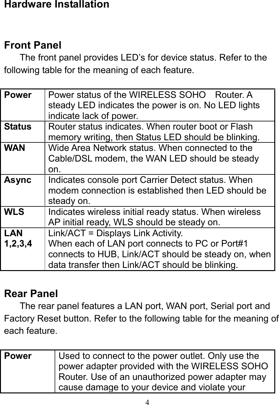
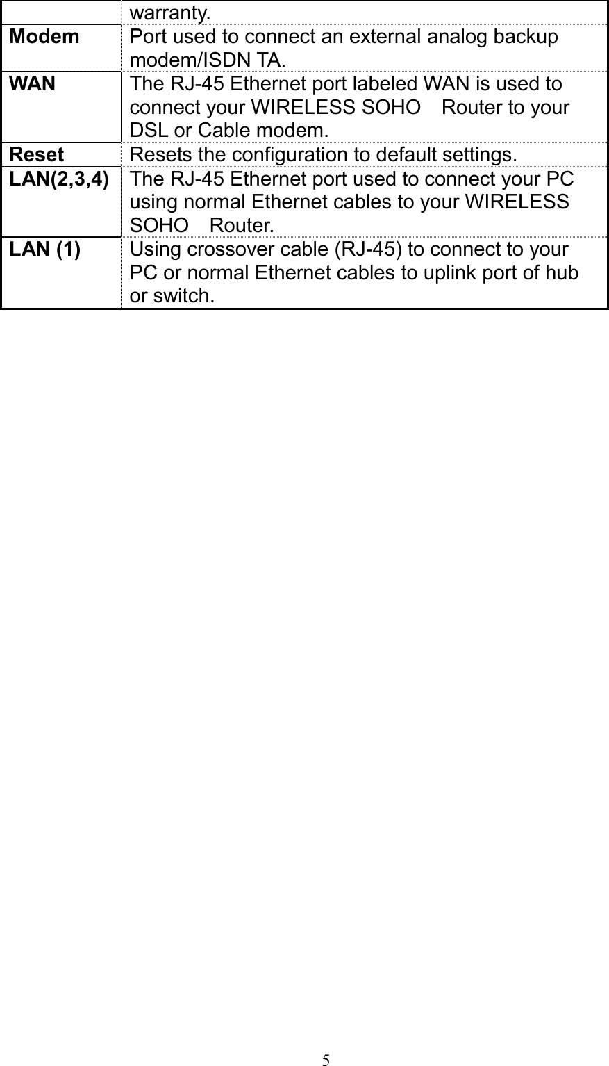
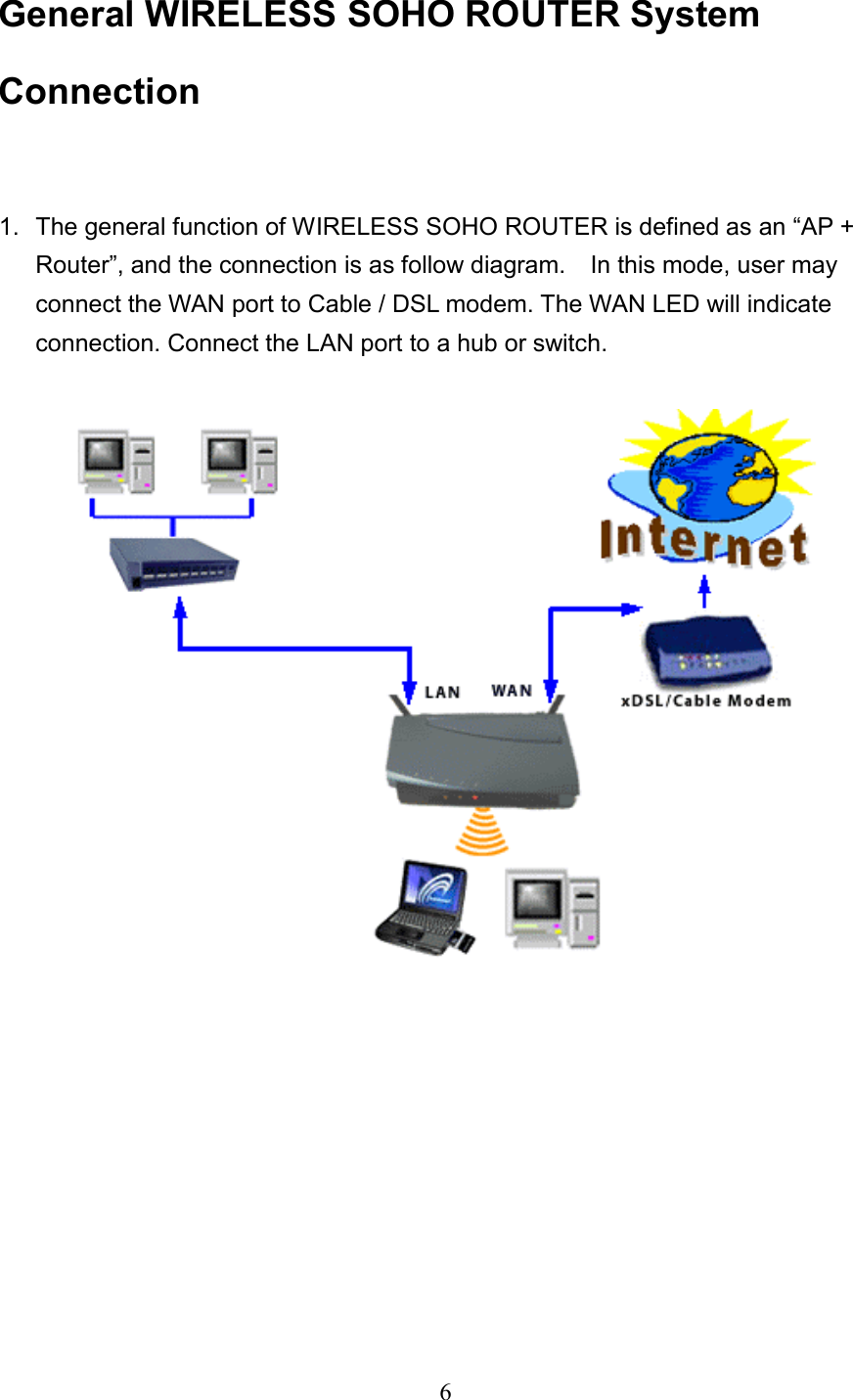
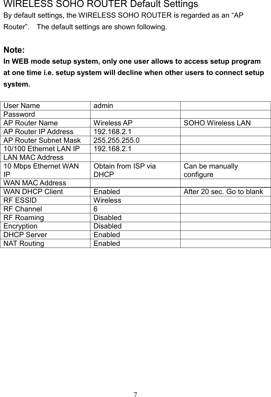
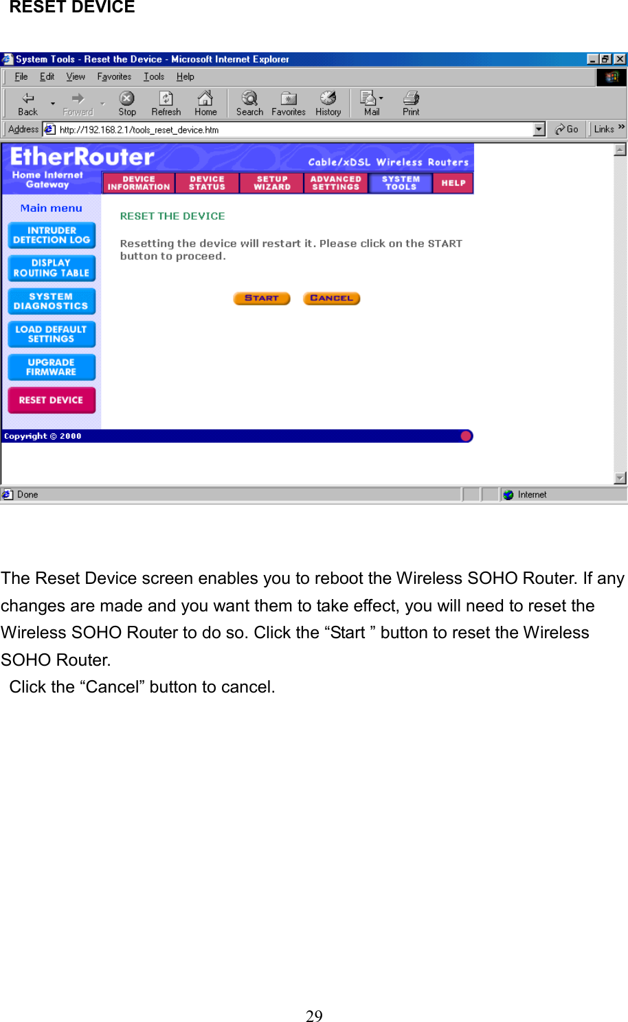
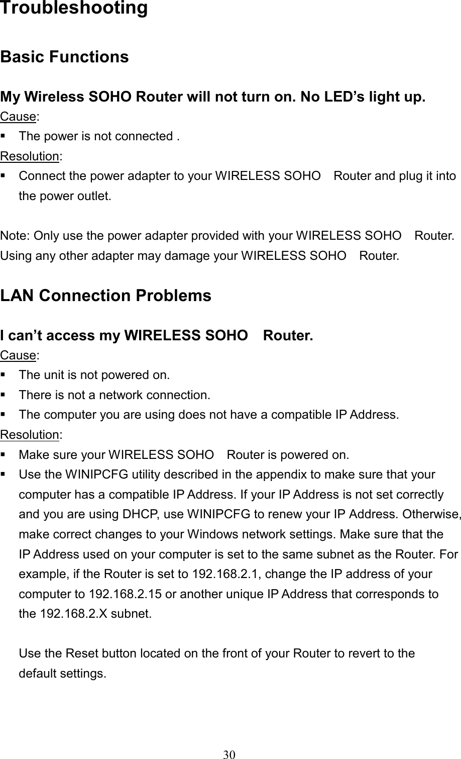
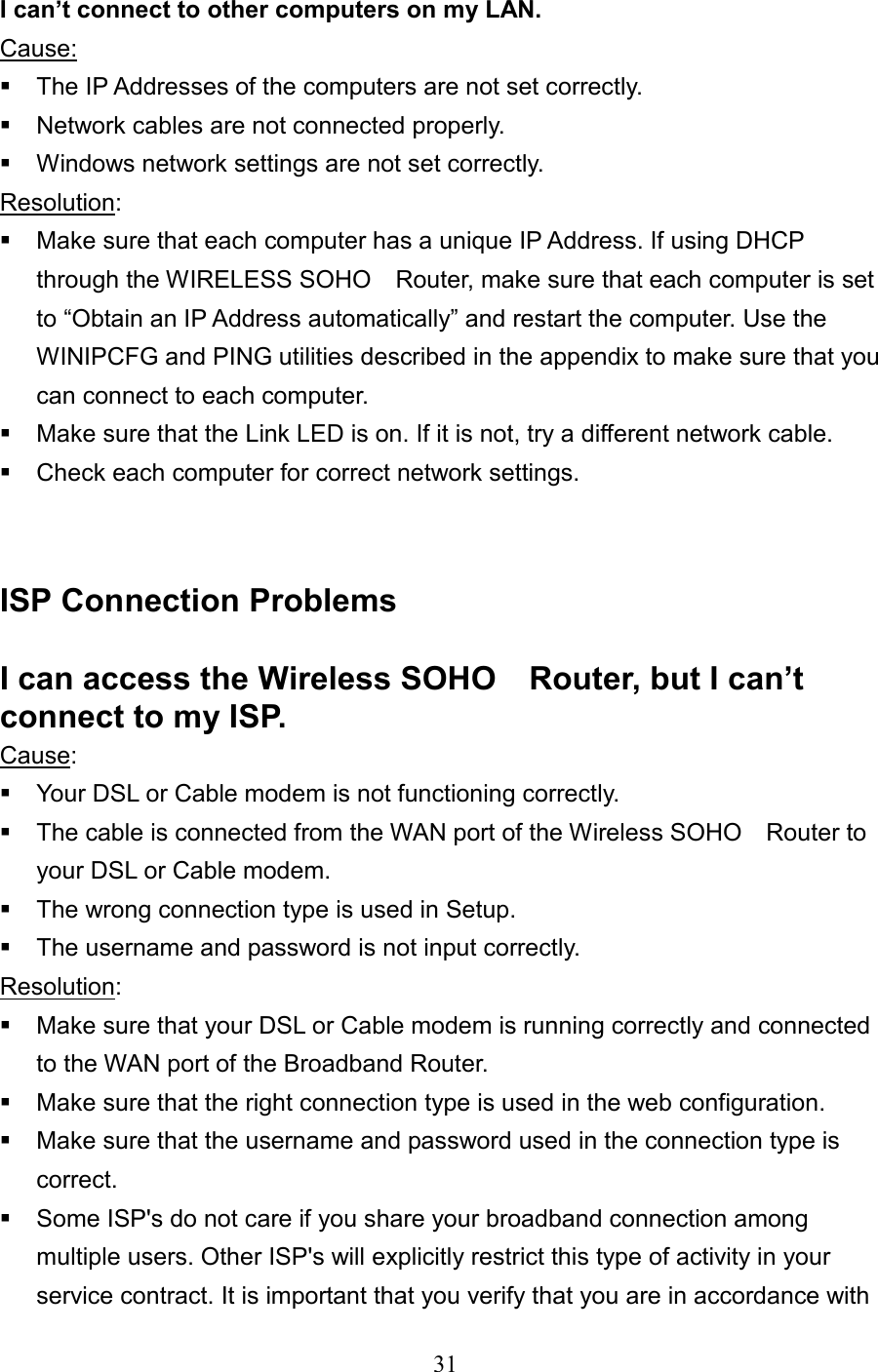
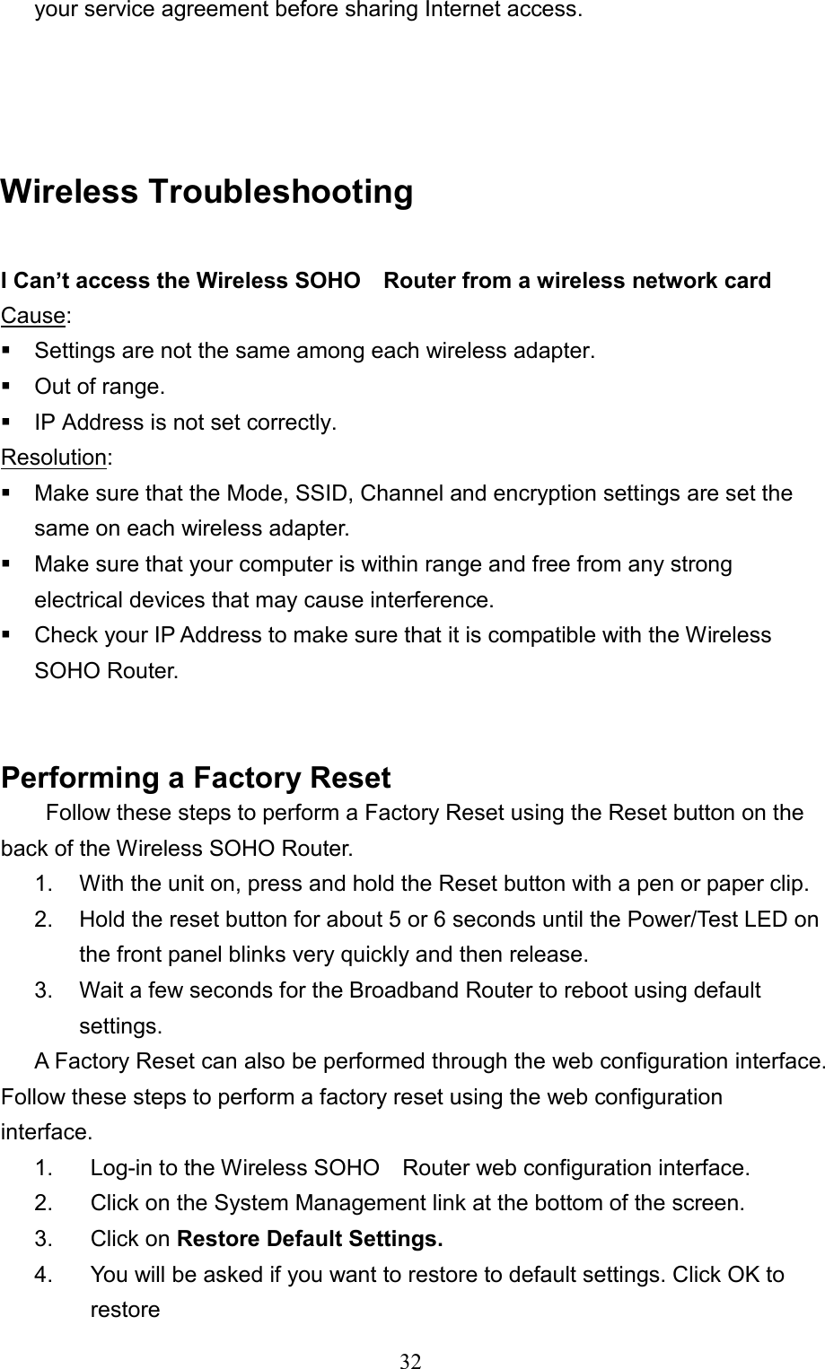
Users Manual
2.
DoC Sheet
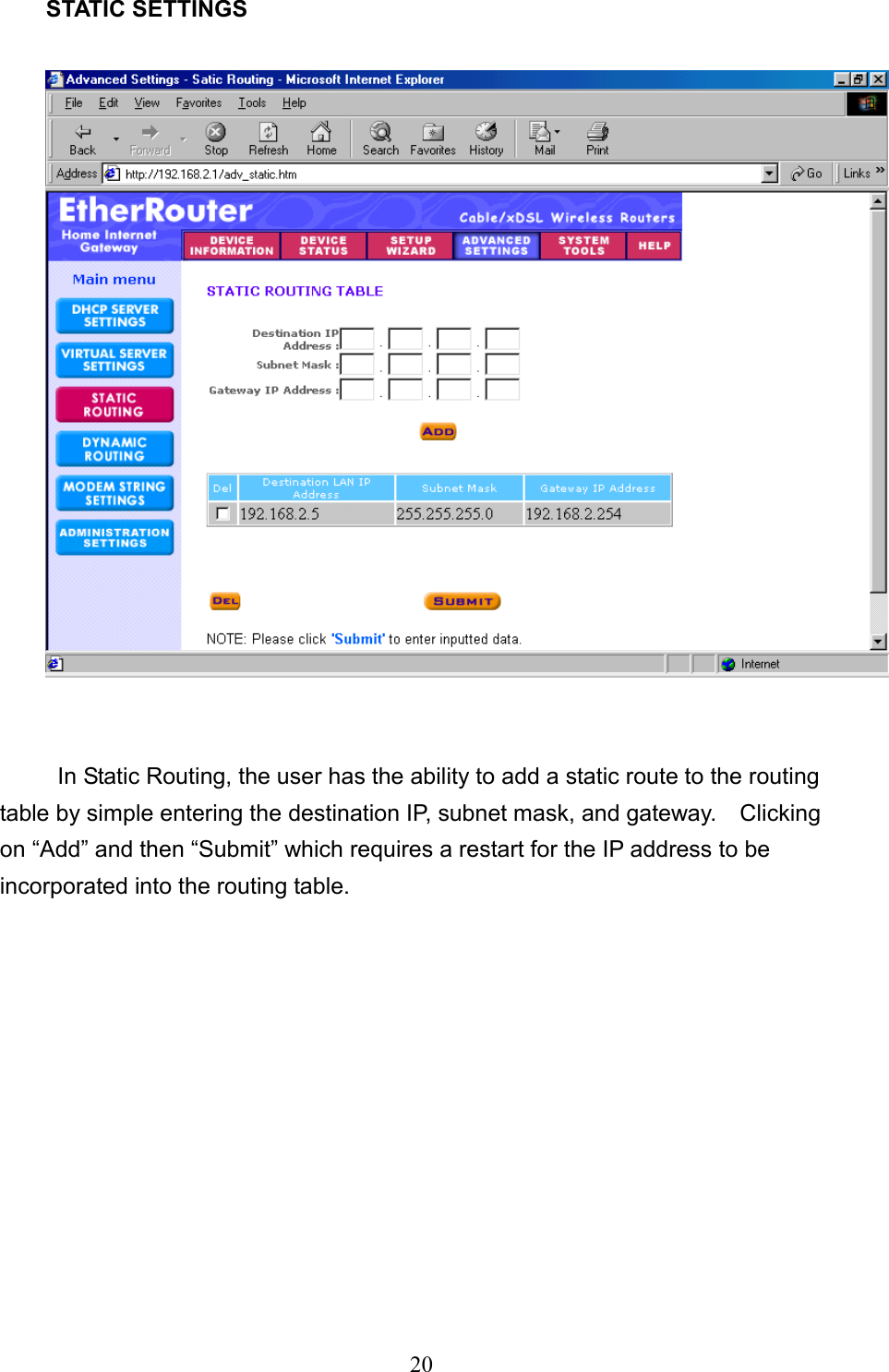
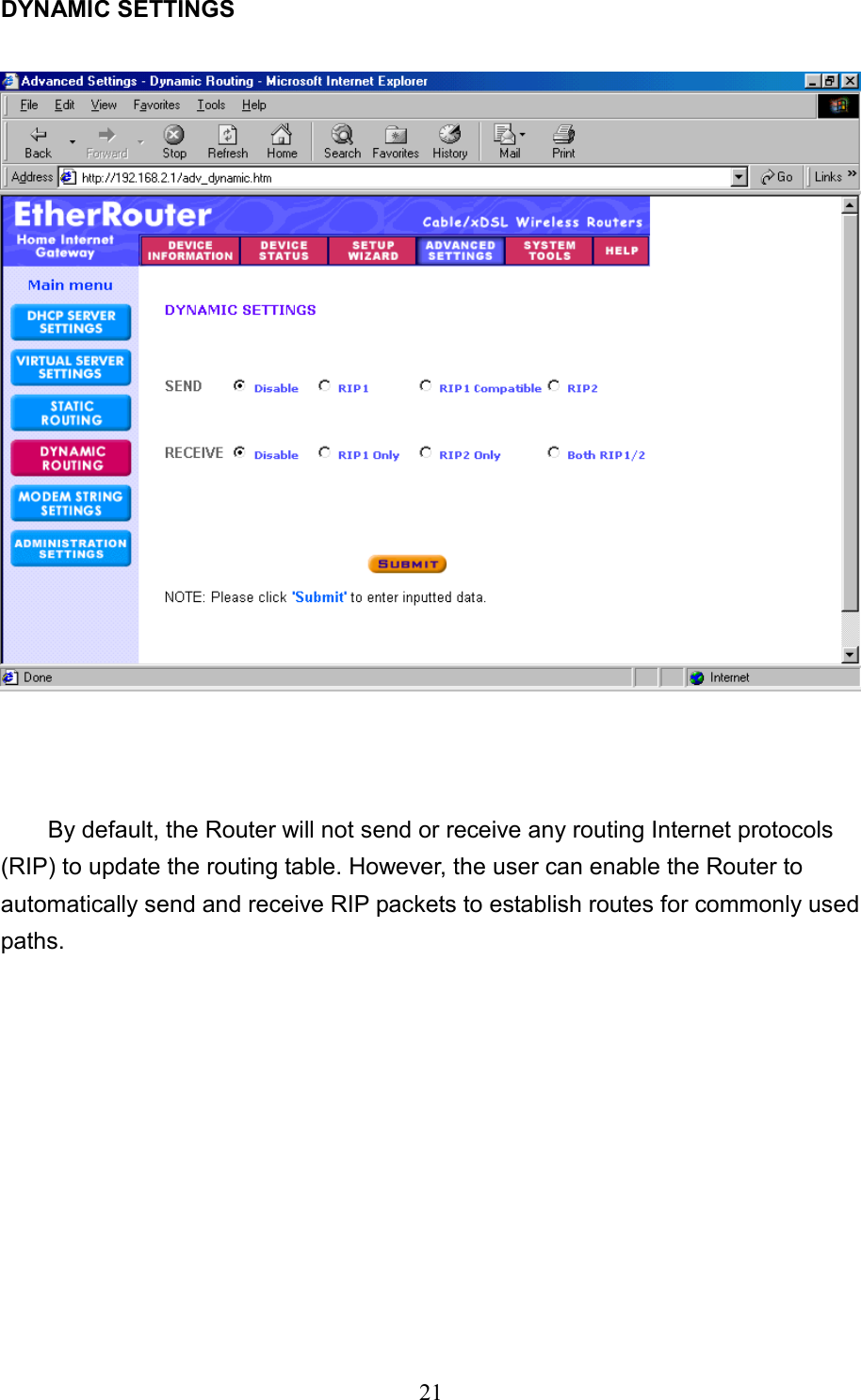
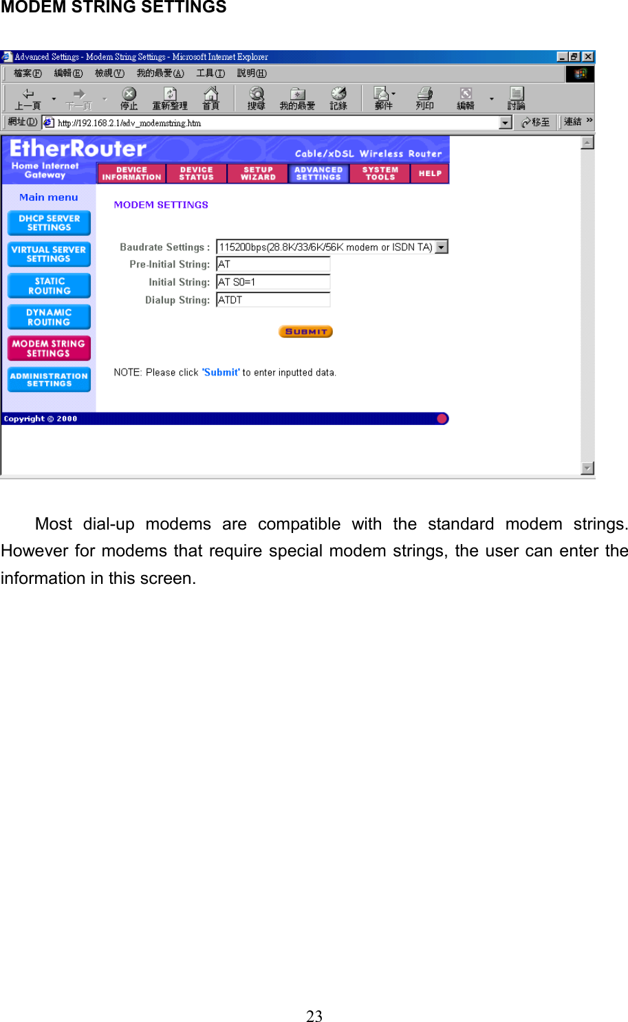
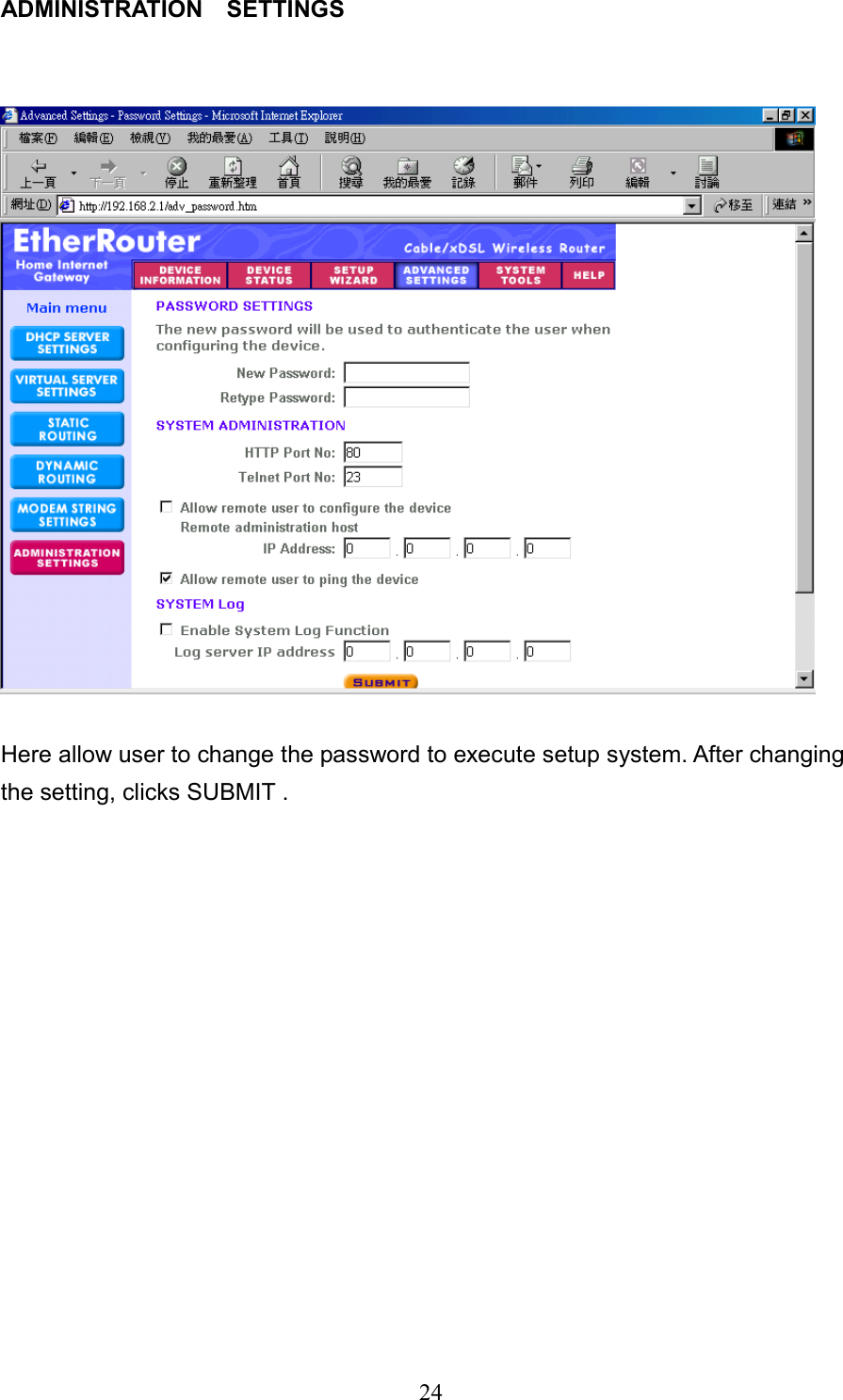
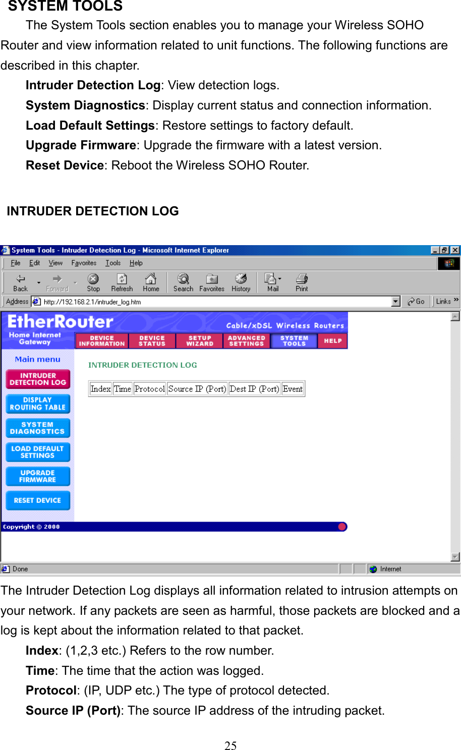
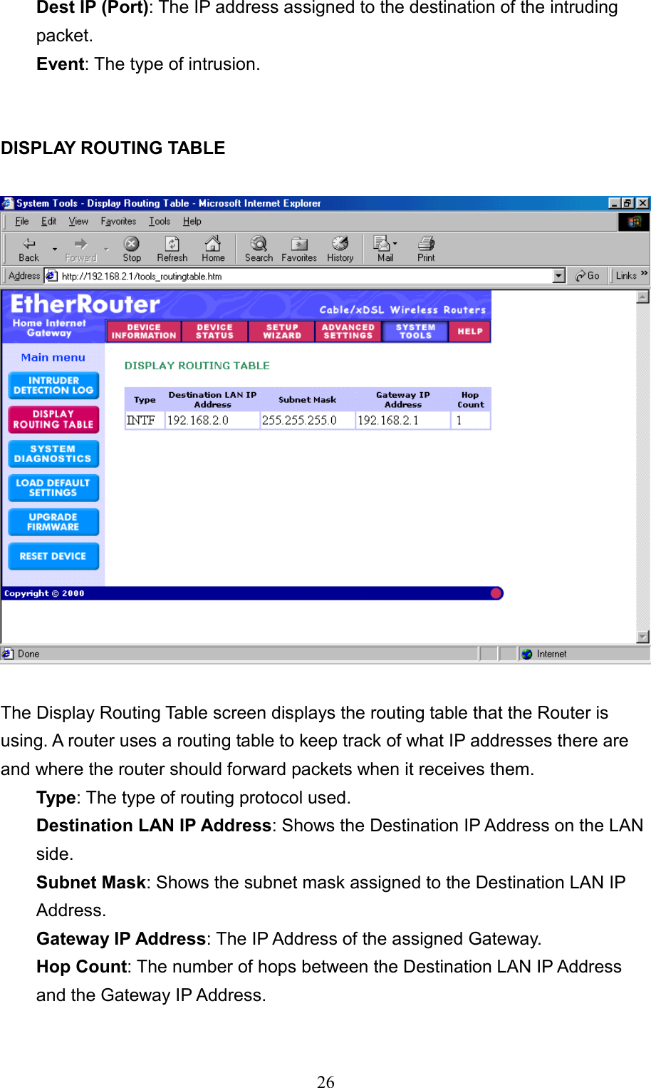
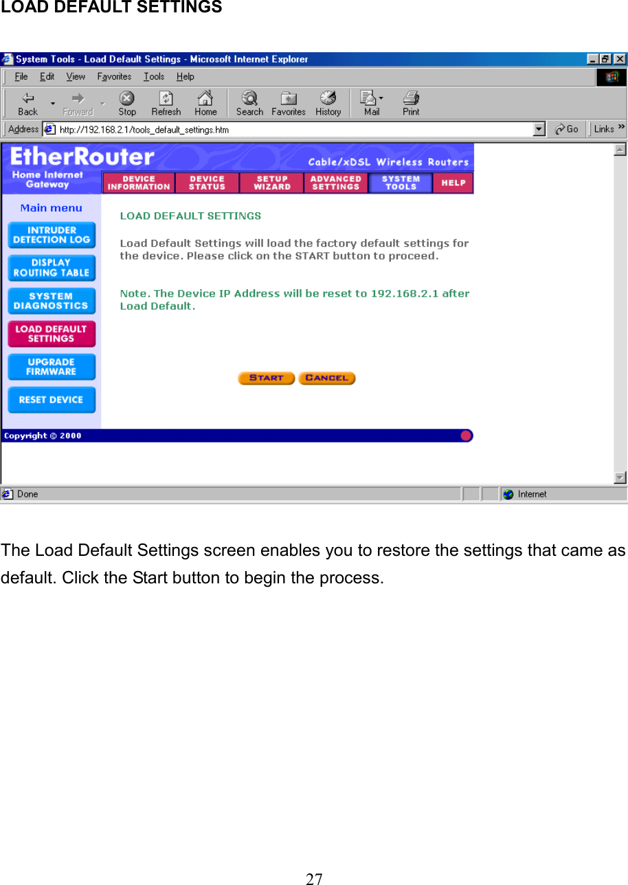
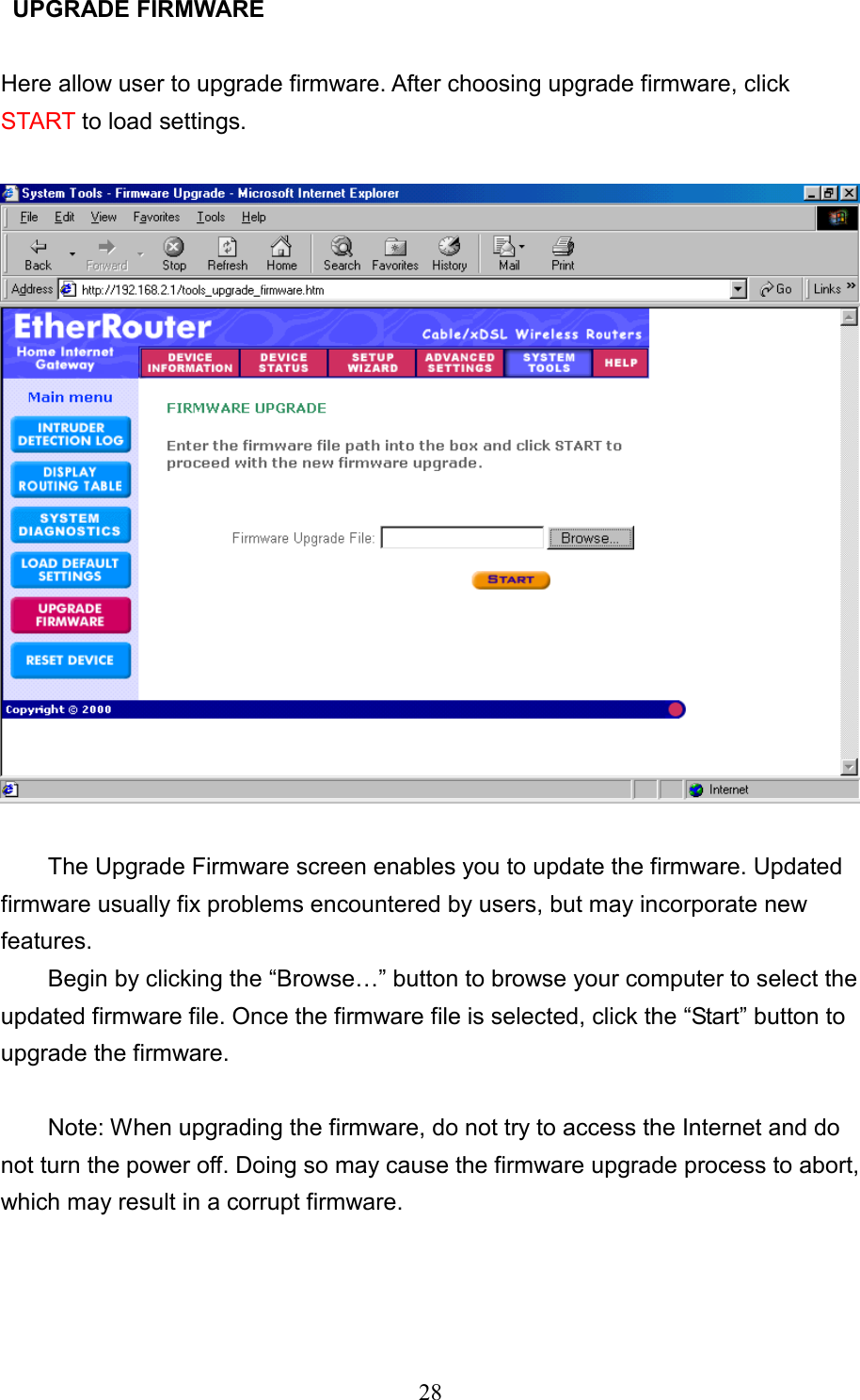
Users Manual
Navigation menu
Upload a User Manual
Namespaces
Wiki Guide
HTML
PDF
Info
Views
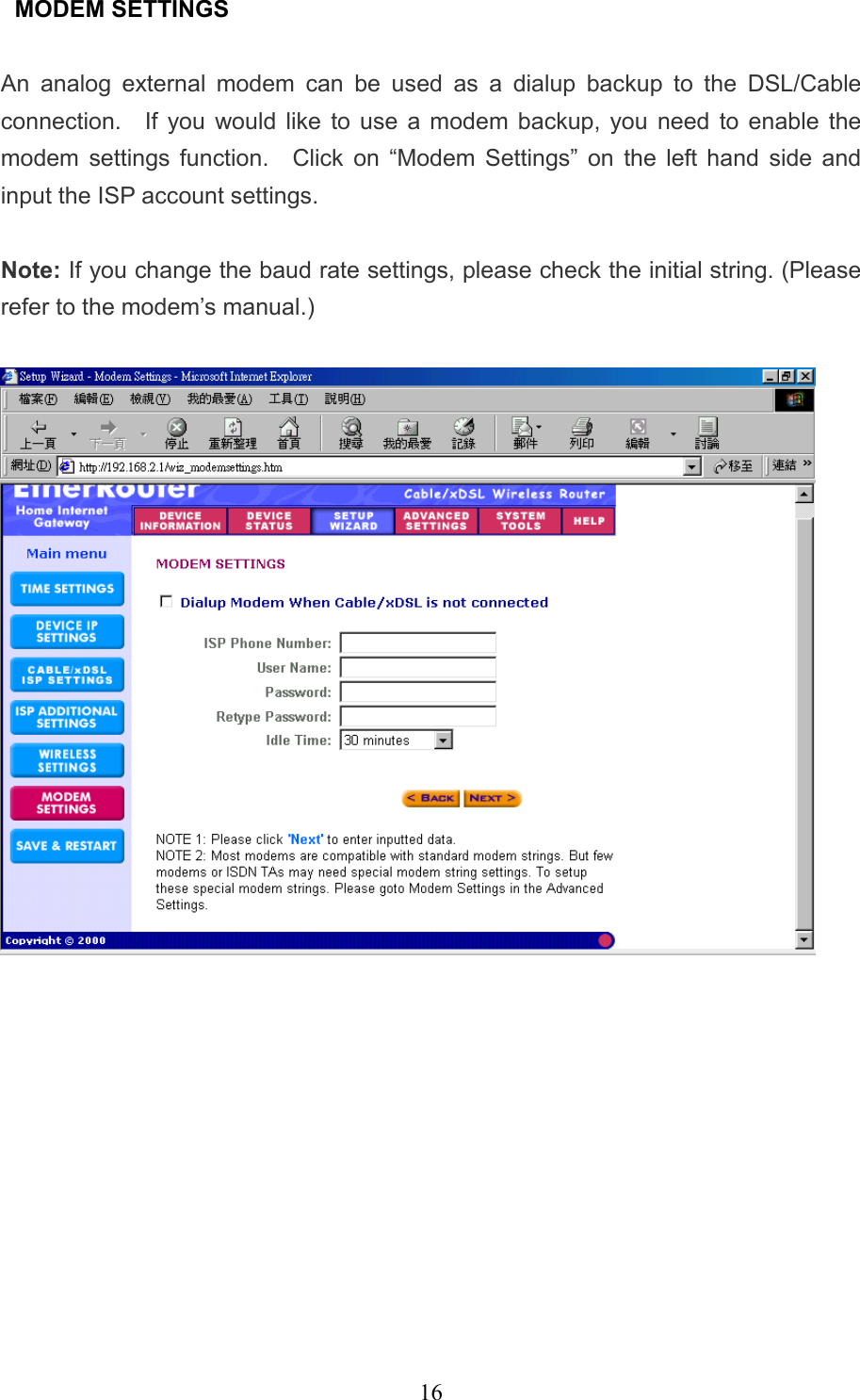
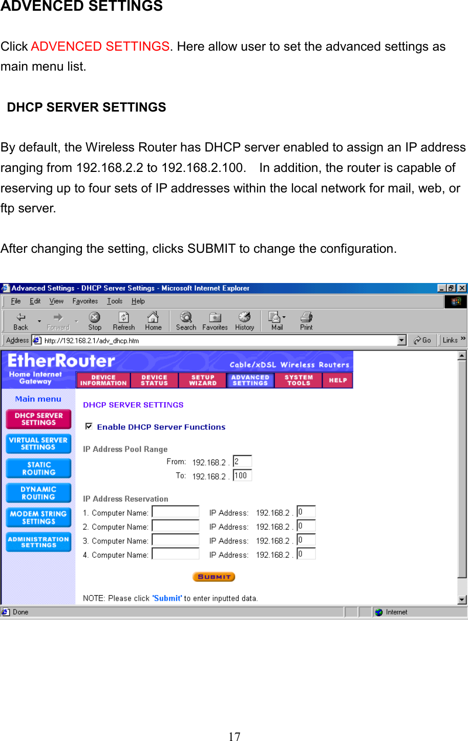
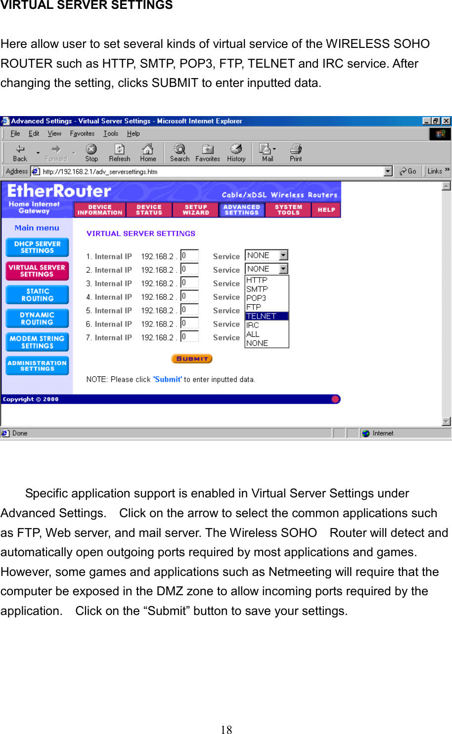
User Manual
Discussion / Help
Navigation