GemTek Technology R911129 WLAN Inter-Building Router User Manual P380 users guide UL
Gemtek Technology Co., Ltd. WLAN Inter-Building Router P380 users guide UL
UserManual.wiki
>
GemTek Technology
>
R911129 User Manual
Manual
Navigation menu
Upload a User Manual
Namespaces
Wiki Guide
HTML
PDF
Info
Views
User Manual
Discussion / Help
Navigation
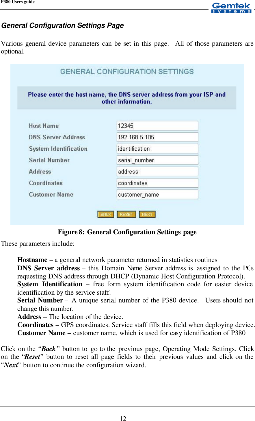
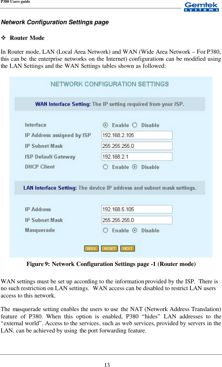
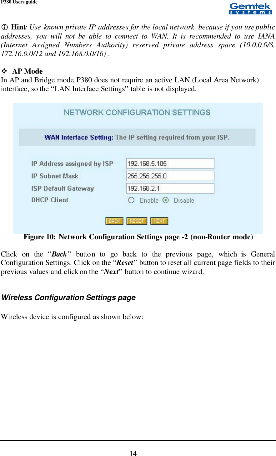
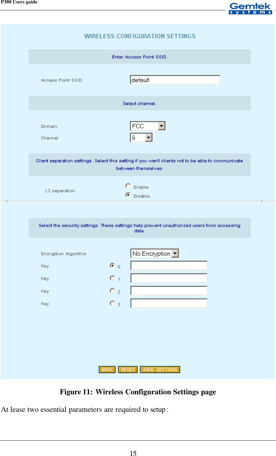
![P380 Users guide 44 Topology A network topology shows the computers and the links between them. A network layer must know the current network topology to be able to route packets to their final destination. U UDP User Datagram Protocol. A transport layer protocol in the TCP/IP suite of protocols. UDP, like TCP, uses IP for delivery; however, unlike TCP, UDP provides for exchange of datagrams without acknowledgements or guaranteed delivery. URL Uniform Resource Locator. A standard format for specifying the name, type and location of documents and resources on an Internet. The syntax is type://host.domain[:port]/path/filename, where type specifies the type of document or resource (e.g. http is a file on a WWW server; file is a file on an anonymous FTP server; telnet is a connection to a Telnet-based service). See WWW. W WAN Wide Area Network. Any physical network technology that spans large geographic distances. WANs usually operate a slower speeds than LANs. See LAN. WWW World Wide Web. A hypertext-based, distributed information system based on client - server architecture. Web browsers (client applications) request documents from Web servers. Documents may contain text, graphics and audiovisual data, as well as links to other documents and services. Web servers and documents are identified by URLs (Uniform Resource Locators). See URL.](https://usermanual.wiki/GemTek-Technology/R911129/User-Guide-289051-Page-44.png)