GemTek Technology R950829G High Performance Hotspot Access Point User Manual BW1330 UG v1 0
Gemtek Technology Co., Ltd. High Performance Hotspot Access Point BW1330 UG v1 0
UserManual.wiki
>
GemTek Technology
>
R950829G User Manual
>
Manual Part 1
Contents
1.
Manual Part 1
2.
Manual Part 2
3.
Manual Part 3
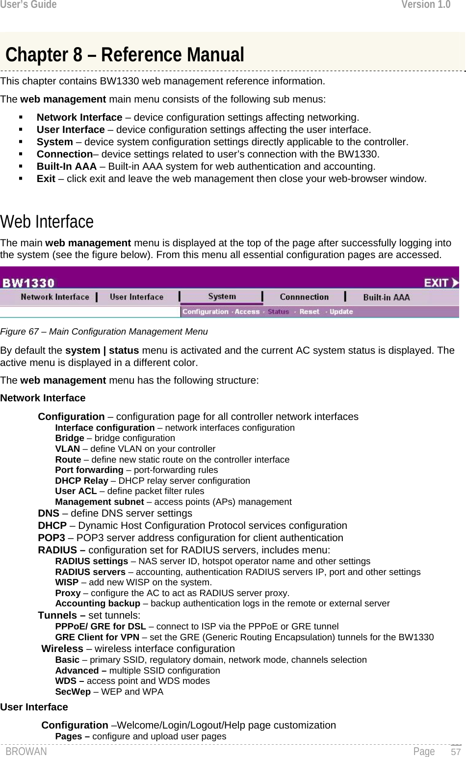
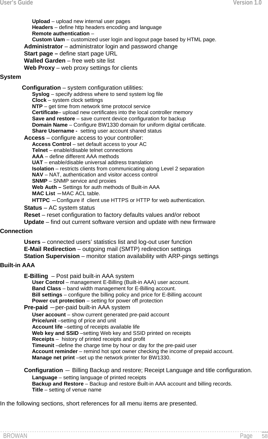
Manual Part 1
Navigation menu
Upload a User Manual
Namespaces
Wiki Guide
HTML
PDF
Info
Views
User Manual
Discussion / Help
Navigation

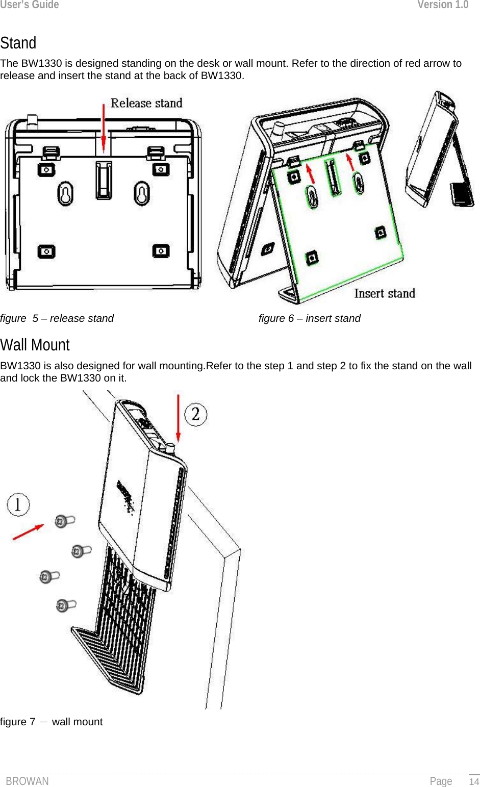
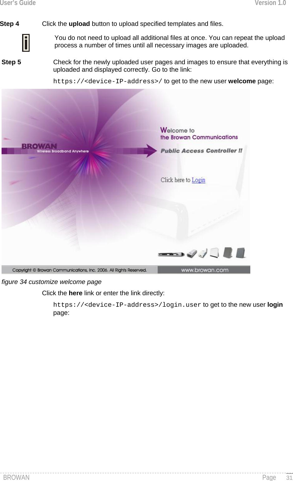
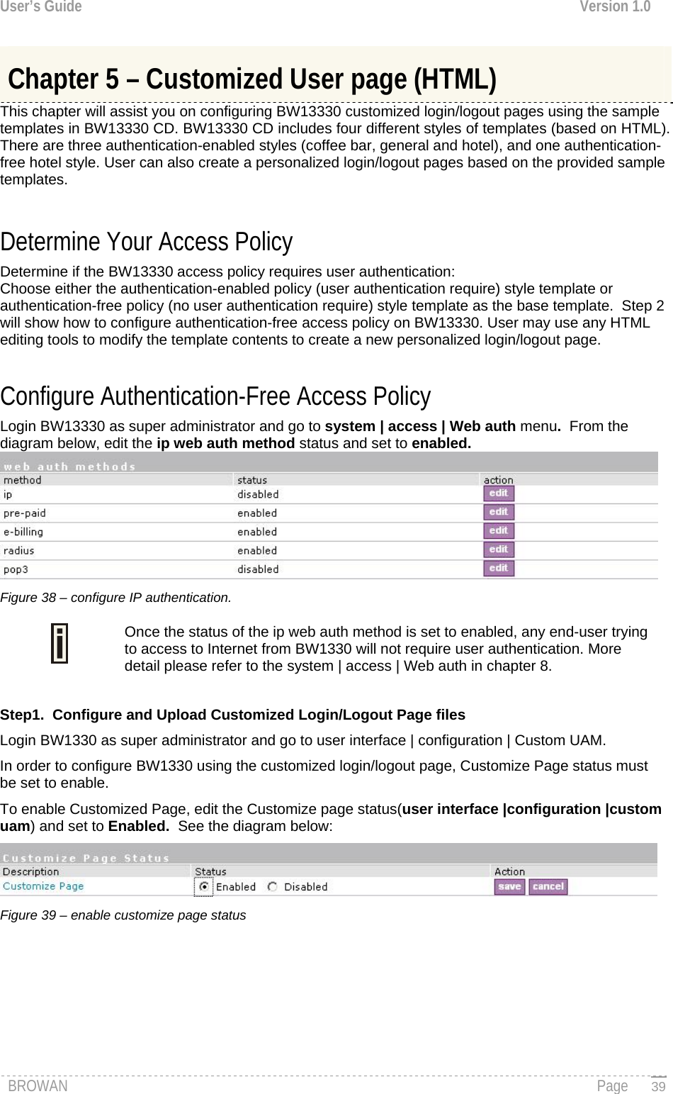
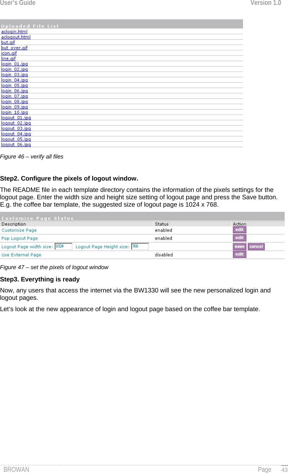
![User’s Guide Version 1.0 About this Guide Purpose This document provides information and procedures on hardware installation, setup, configuration, and management of the Browan Communications high performance hotspot access point model BW1330. The BW1330 is a highly integrated Access Controller with built-in AAA systems for public access hotspot. We will call it AC later in the manual. Prerequisite Skills and Knowledge To use this document effectively, you should have a working knowledge of Local Area Networking (LAN) concepts and wireless Internet access infrastructures. In addition, you should be familiar with the following: Hardware installers should have a working knowledge of basic electronics and mechanical assembly, and should understand related local building codes. Network administrators should have a solid understanding of software installation procedures for network operating systems under Microsoft Windows 95, 98, Millennium, 2000, NT, and Windows XP and general networking operations and troubleshooting knowledge. Conventions Used in this Document The following typographic conventions and symbols are used throughout this document: Very important information. Failure to observe this may result in damage. Important information that should be observed. Additional information that may be helpful but which is not required. Menu commands, buttons and input fields are displayed in bold bold code File names, directory names, form names, and system-generated output such as error messages are displayed in constant-width type <value> Placeholder for certain values, e.g. user inputs [value] Input field format, limitations, and/or restrictions. Help Us to Improve this Document! If you should encounter mistakes in this document or want to provide comments to improve the manual please send e-mail directly to: manuals@browan.com Browan Communications Technical Support If you encounter problems when installing or using this product, please consult the Browan Communications website at http://www.browan.com/ for: Direct contact to the Browan Communications support centers. Frequently Asked Questions (FAQ). Download area for the latest software, user documentation and product updates. BROWAN Page 7](https://usermanual.wiki/GemTek-Technology/R950829G.Manual-Part-1/User-Guide-716069-Page-9.png)
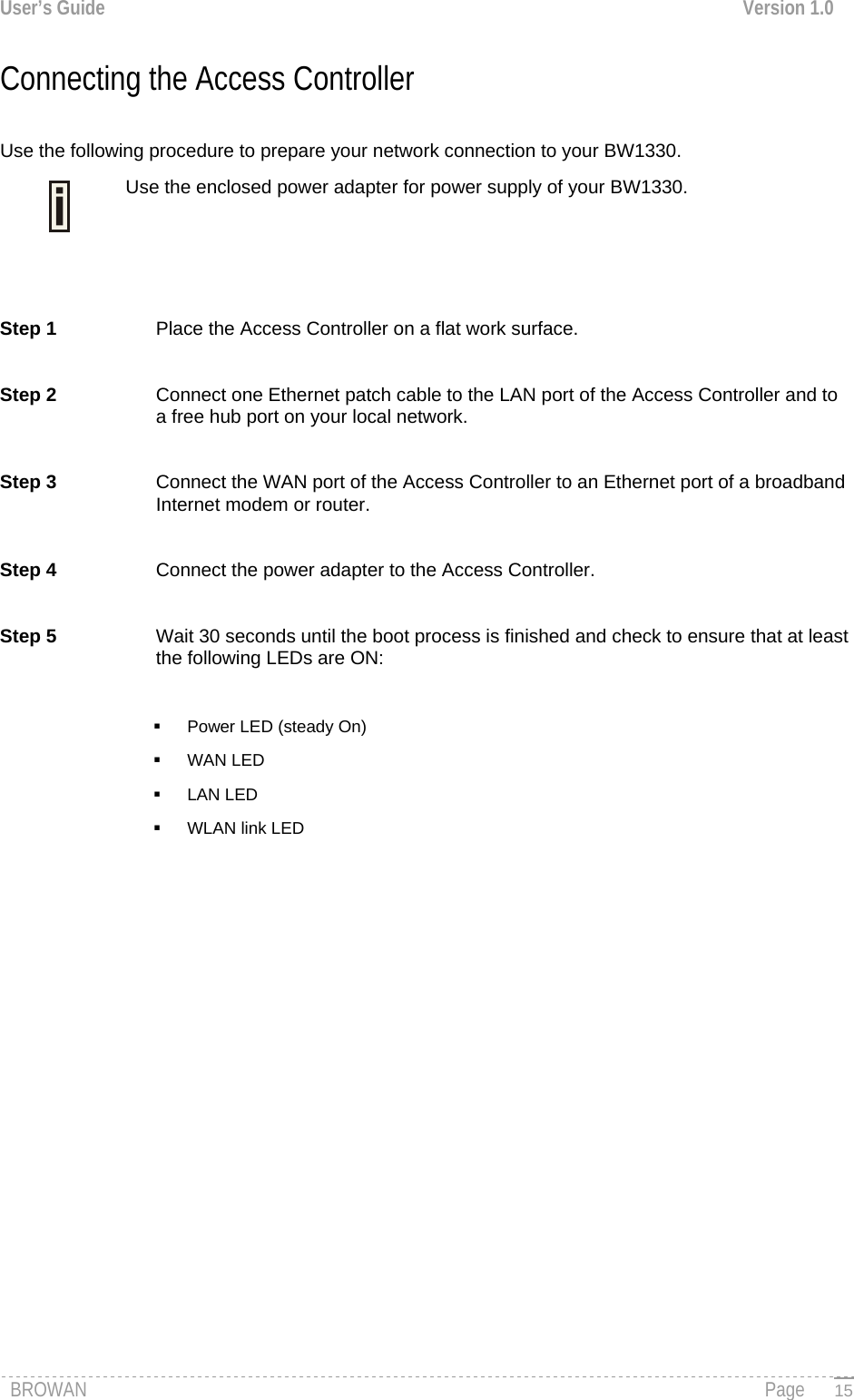
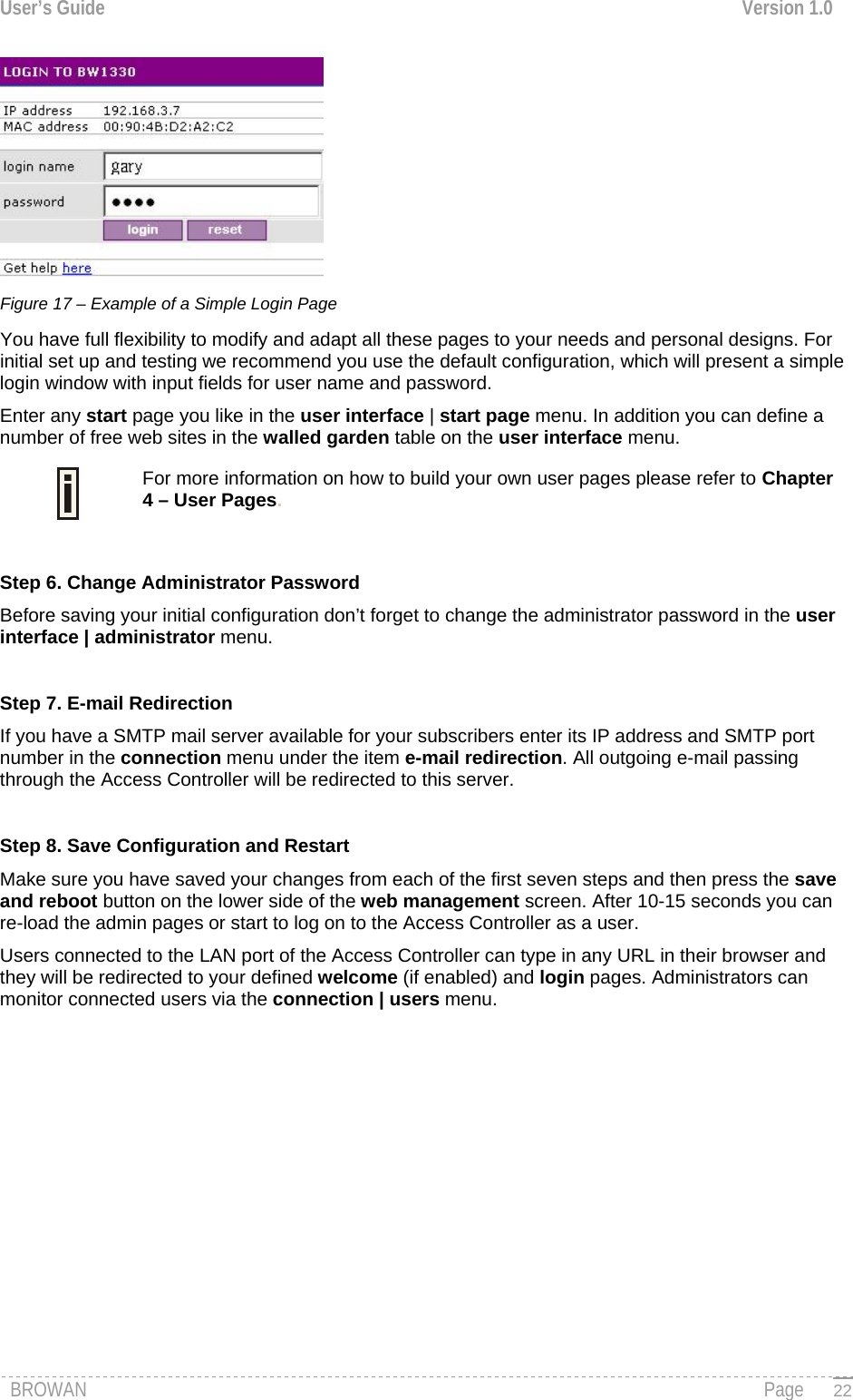
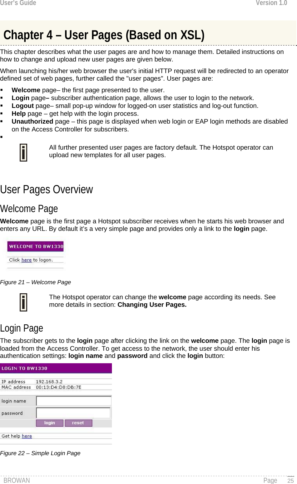
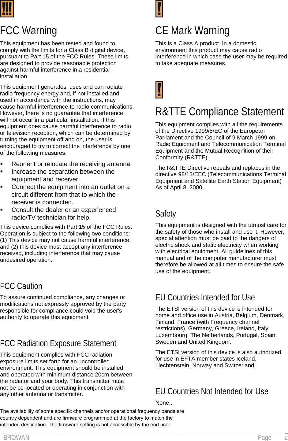
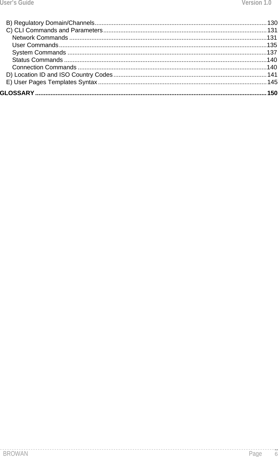
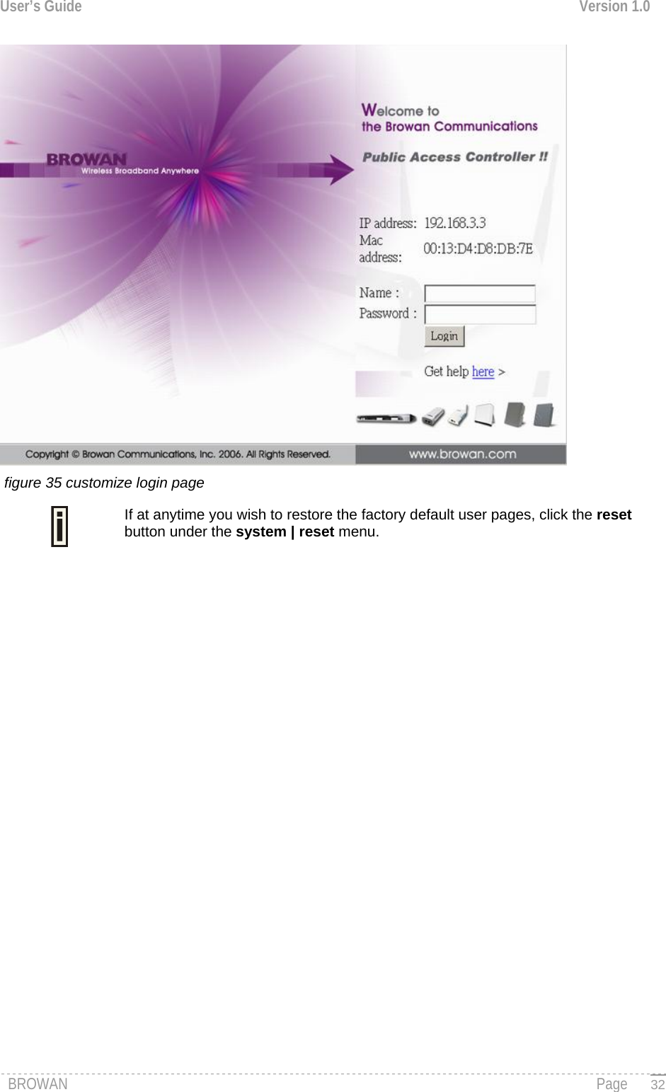
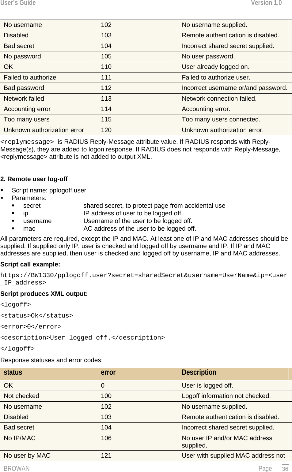
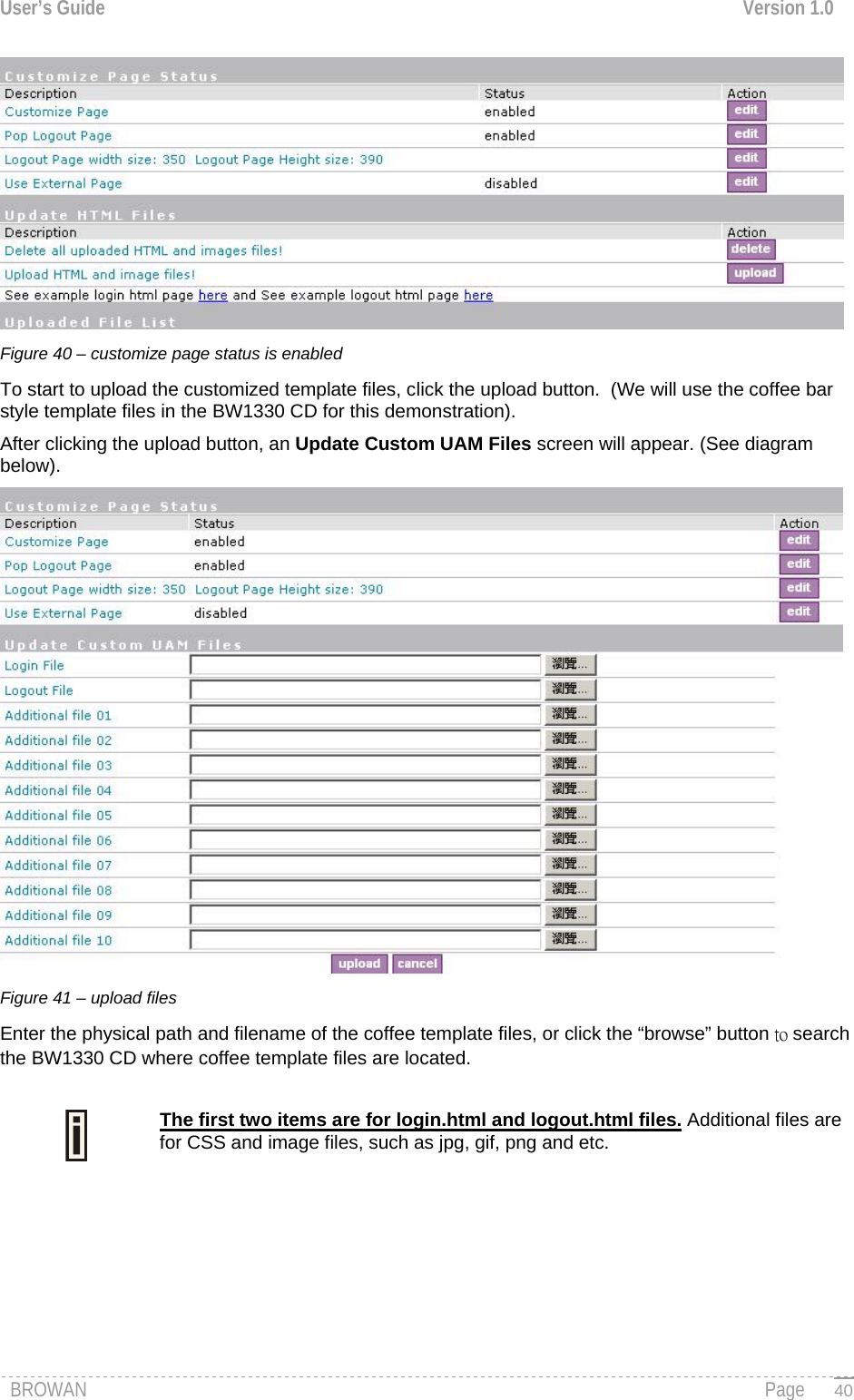
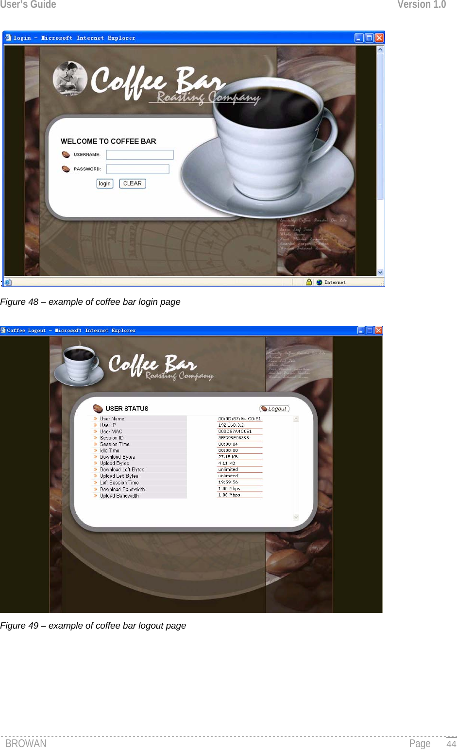
![User’s Guide Version 1.0 MAC Address – subscriber’s physical network address. time length– subscriber’s time length from client log on in format: [hours: minutes: seconds]. Download/upload bytes – subscriber’s session download and upload statistics in bytes. Download/upload bytes left – session download and upload bytes left for subscriber limited from RADIUS [in B, KB, MB, GB and unlimited]. Total bytes left – session total (download and upload) bytes left for subscriber limited form RADIUS [in B, KB, MB, GB and unlimited]. time length left – time length left in format: [hours: minutes: seconds]. Bandwidth downstream/upstream – available upstream and downstream bandwidth for subscriber limited from RADIUS [in bps]. Refresh button – click the button to refresh the subscriber session information. The Hotspot operator can change the logout page interface according to its needs. See more details in section: Changing User Pages.. All session details are further accessible via the operator XML interface. Help Page Click on the get help link in the login page for help tips related to network registration. A page appears similar to the following: Figure 24 – Help Page The Hotspot operator can change the help page according to its needs. See more details in section: Changing User Pages. Unauthorized Page If web log-on method (UAM) or EAP-based authentication methods are disabled on the AC and the subscriber attempts to login to the network, he will receive the following page: Figure 25 – Unauthorized Page The Hotspot operator can change the unauthorized page according to its needs. See more details in section: Changing User Pages. BROWAN Page 27](https://usermanual.wiki/GemTek-Technology/R950829G.Manual-Part-1/User-Guide-716069-Page-29.png)
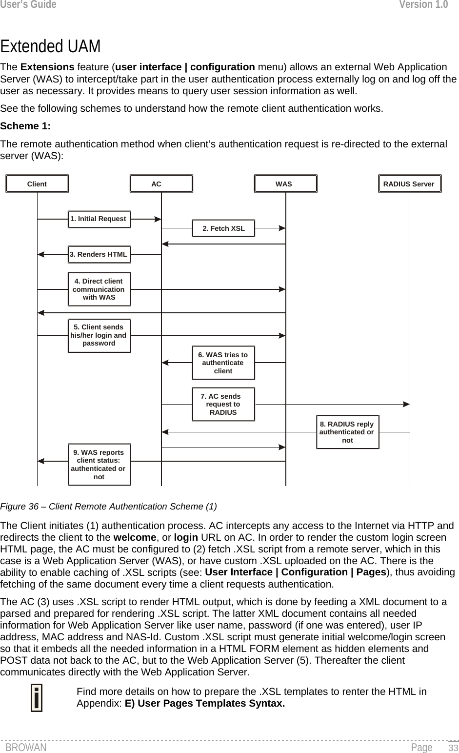
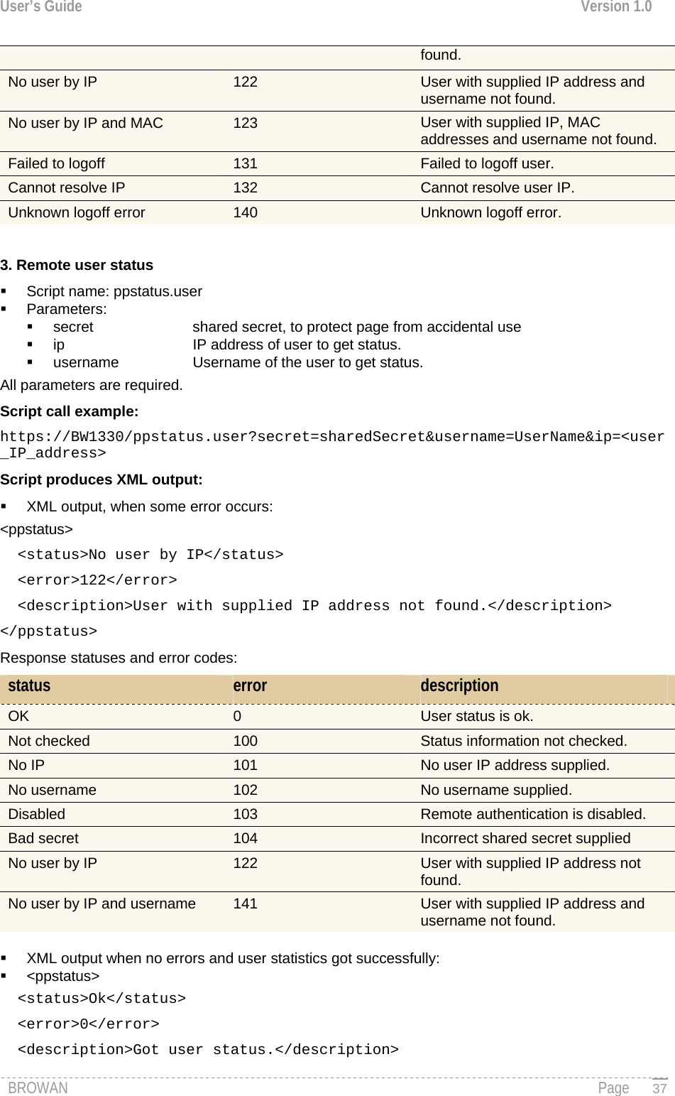
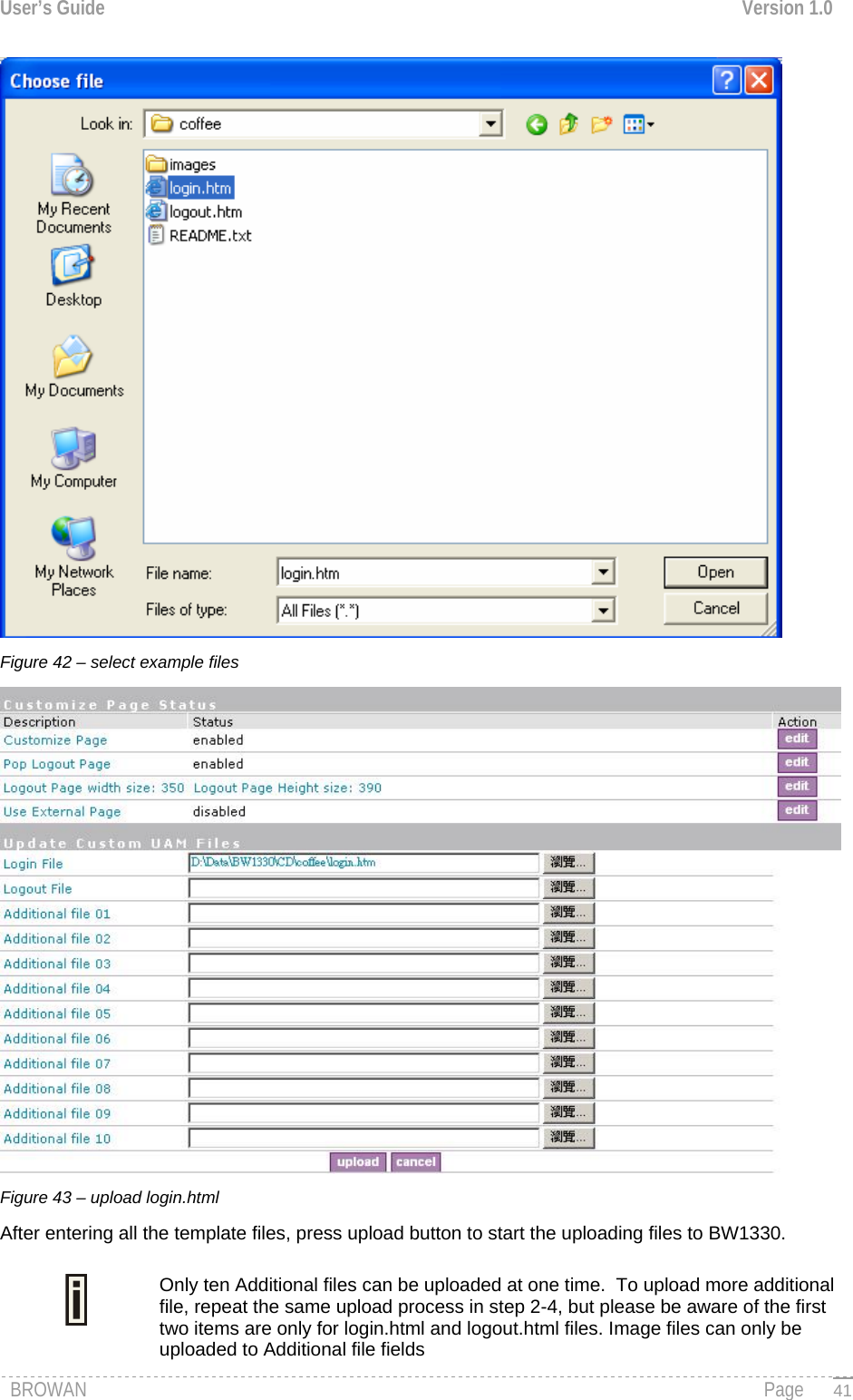
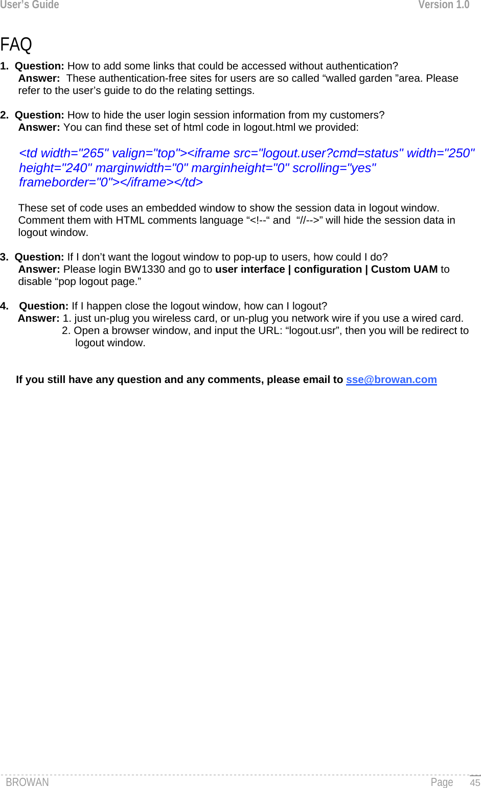
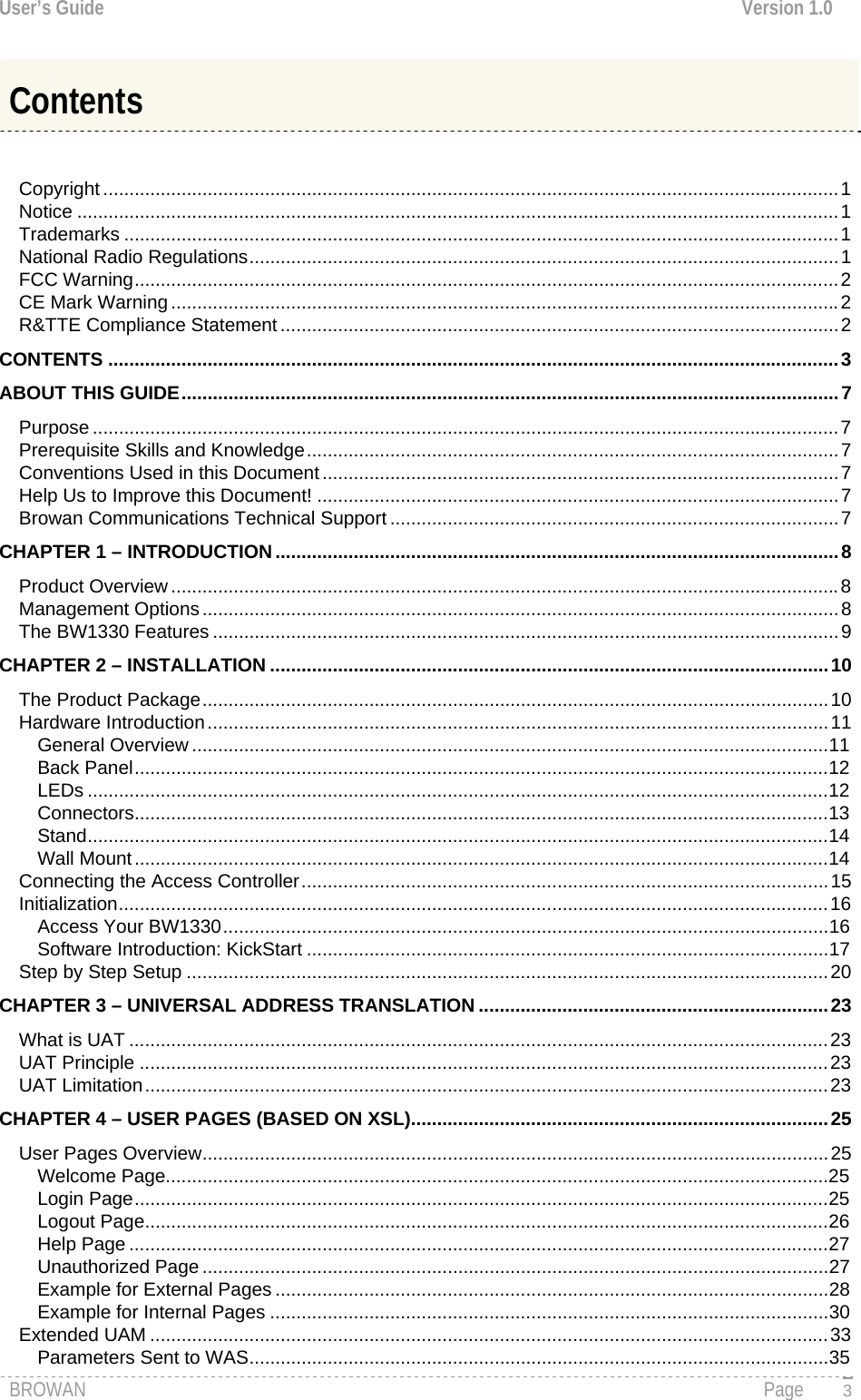
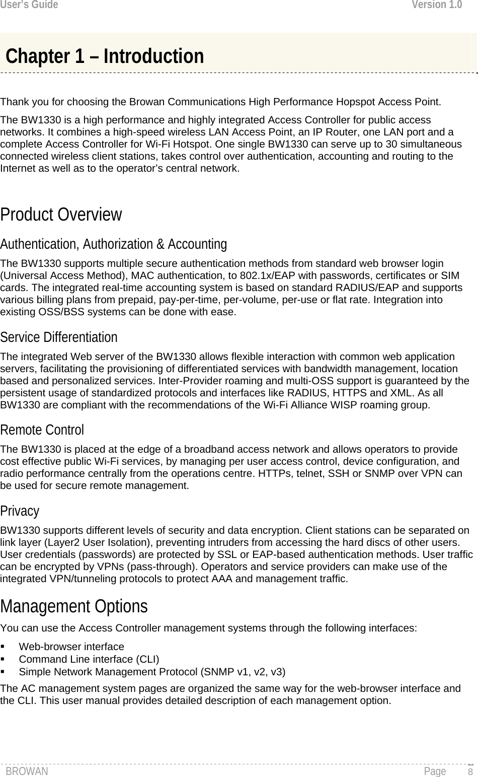
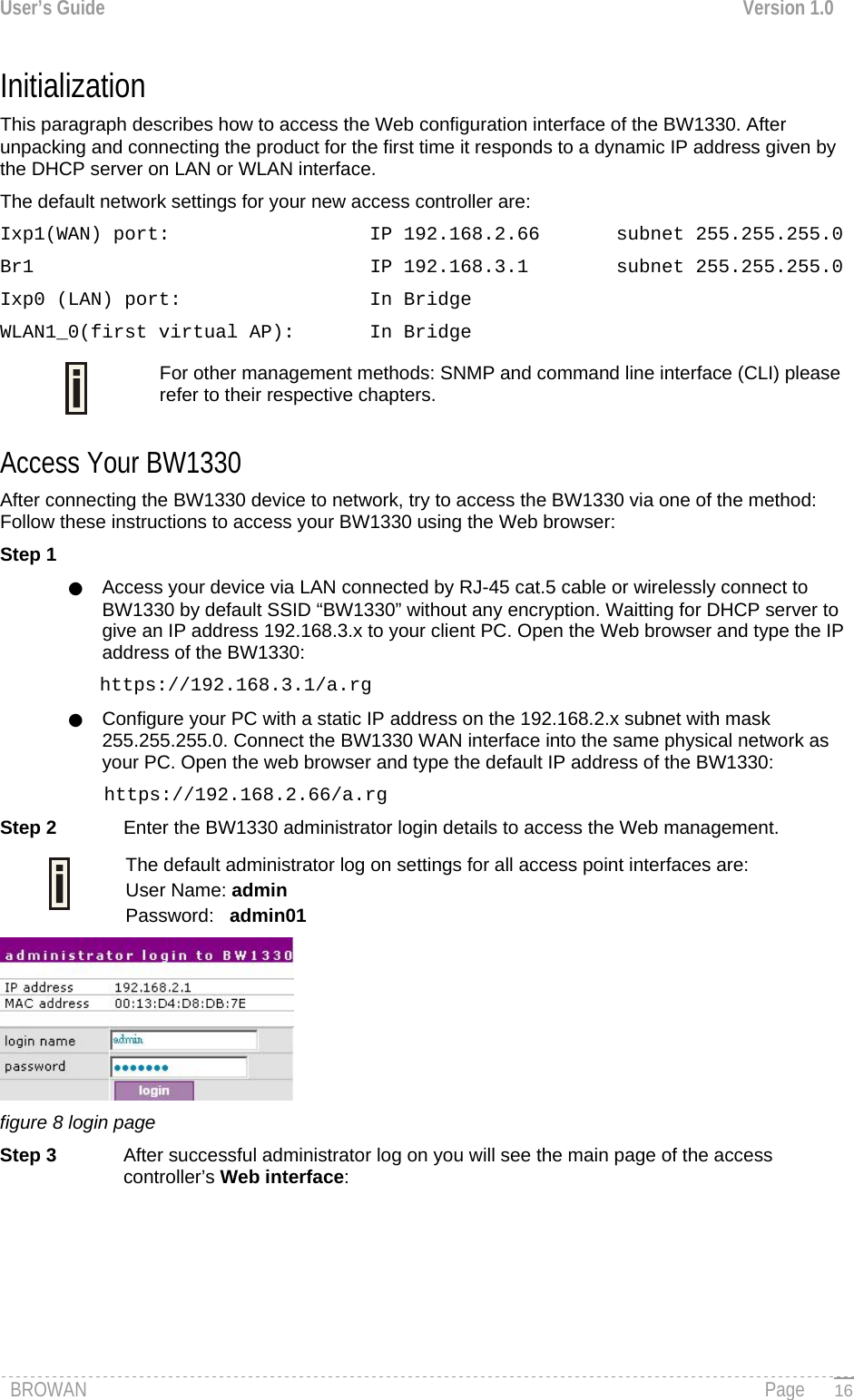
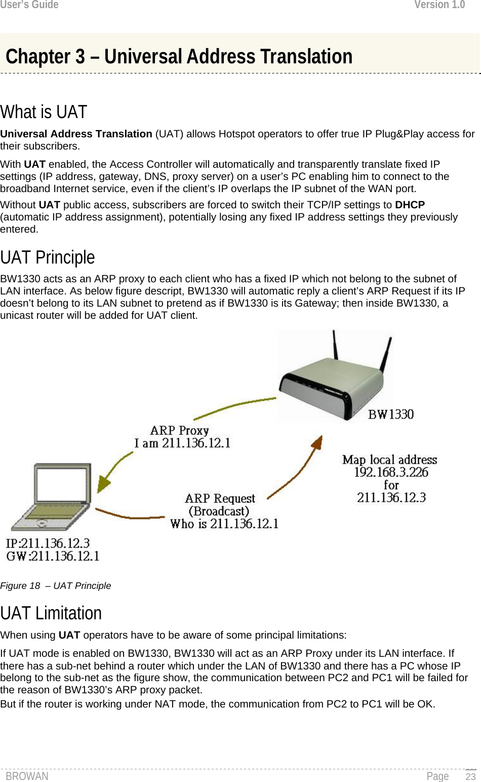
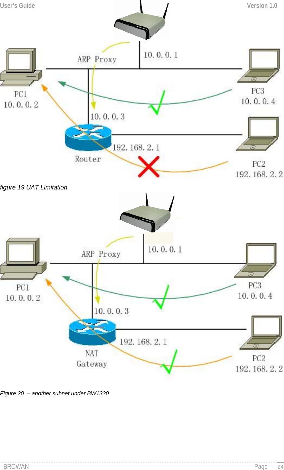
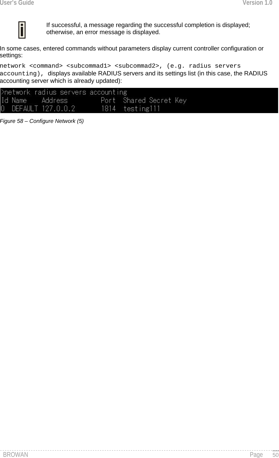
![User’s Guide Version 1.0 Connection Connection is a category of command that is related to the user’s connection with the device. A full list of all available connection commands/subcommands and its parameters is available in the Appendix section: C) CLI Commands and Parameters. In general, connection usage is as follows: connection <command> <value> To get a list of all available commands in the connection category type: connection ? Figure 52 – Connection Commands Network Network is a category of commands that configures controller interface settings, DNS, DHCP, UAT and RADIUS settings. A full list of all available network commands/subcommands and its parameters is available in the Appendix section C) CLI Commands and Parameters. The network commands themselves contain several subcommands and the subcommands again contain several parameters. In general, network command usage is as follows: network <command> <subcommand1> <subcommand2> [-parameter] <value> To get a list of all available commands in the configure category, type: network ? Figure 53 – Network Commands List To get a list of all-available subcommands for a specific command, type: network <command> ?, (e.g. network radius ?) All available subcommands for radius are displayed: BROWAN Page 48](https://usermanual.wiki/GemTek-Technology/R950829G.Manual-Part-1/User-Guide-716069-Page-50.png)
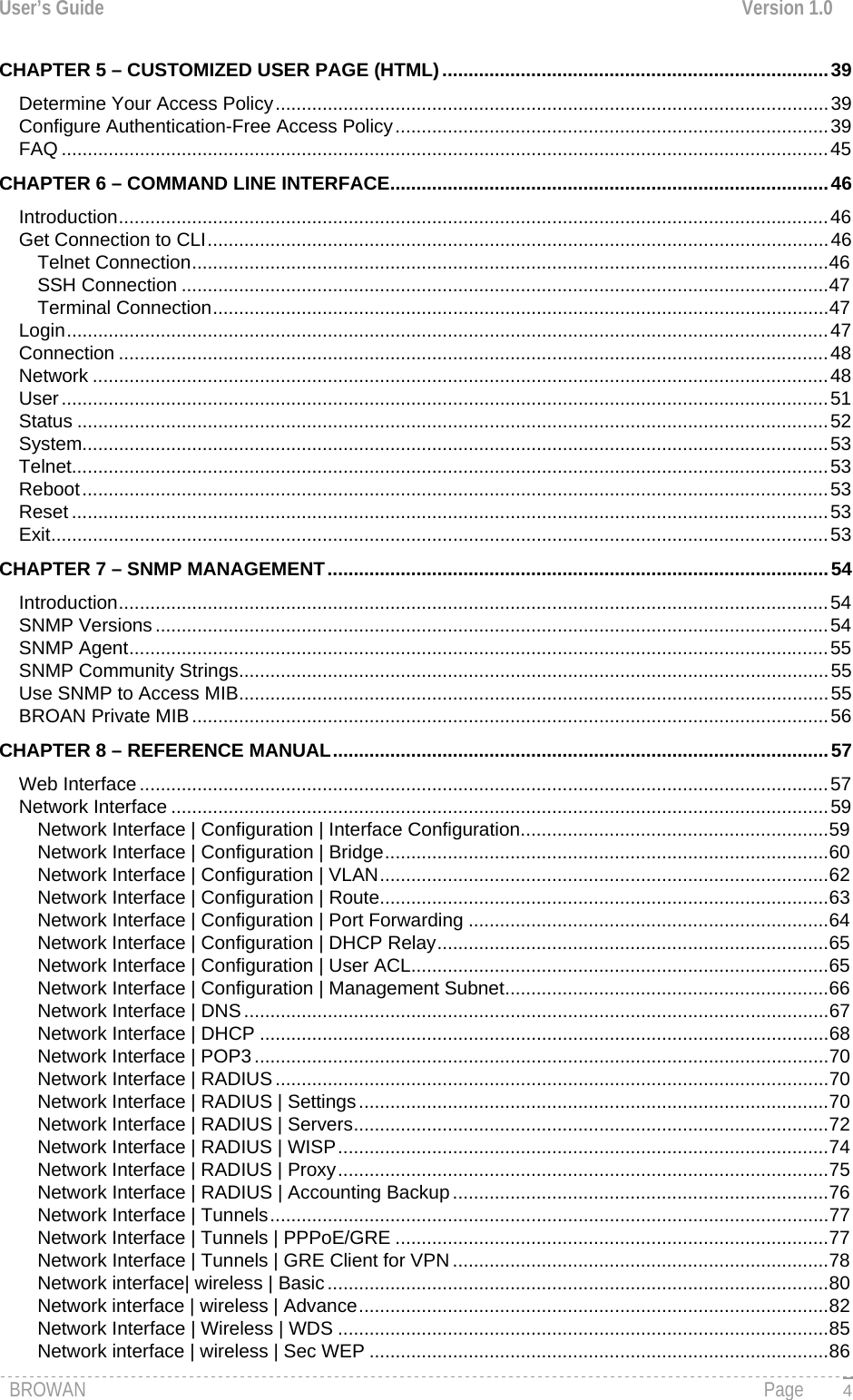
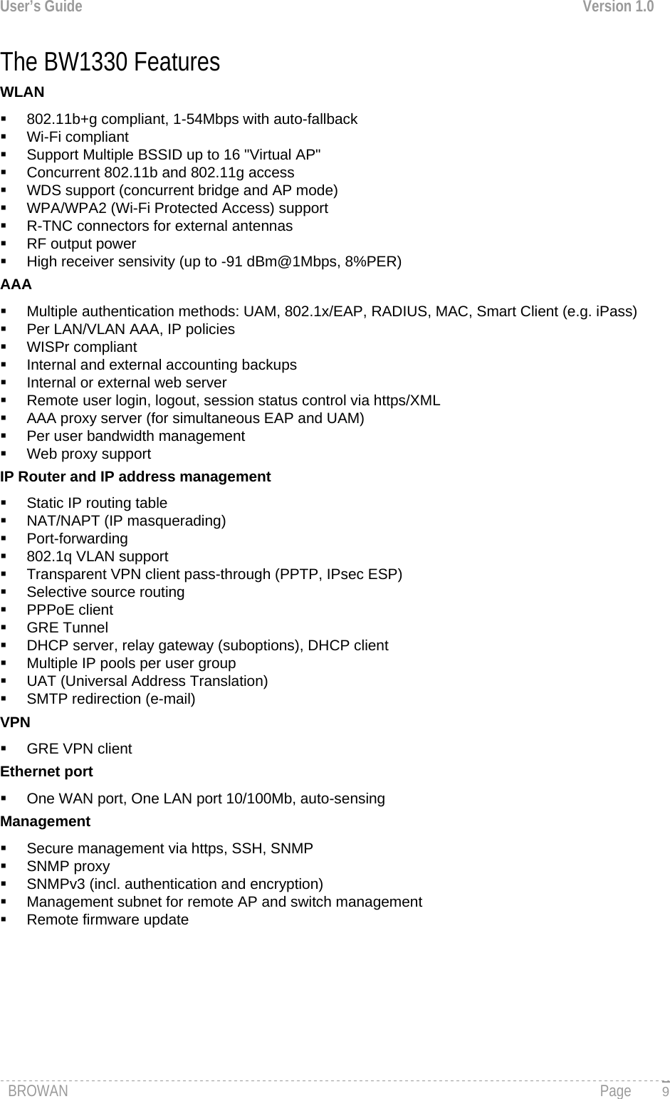
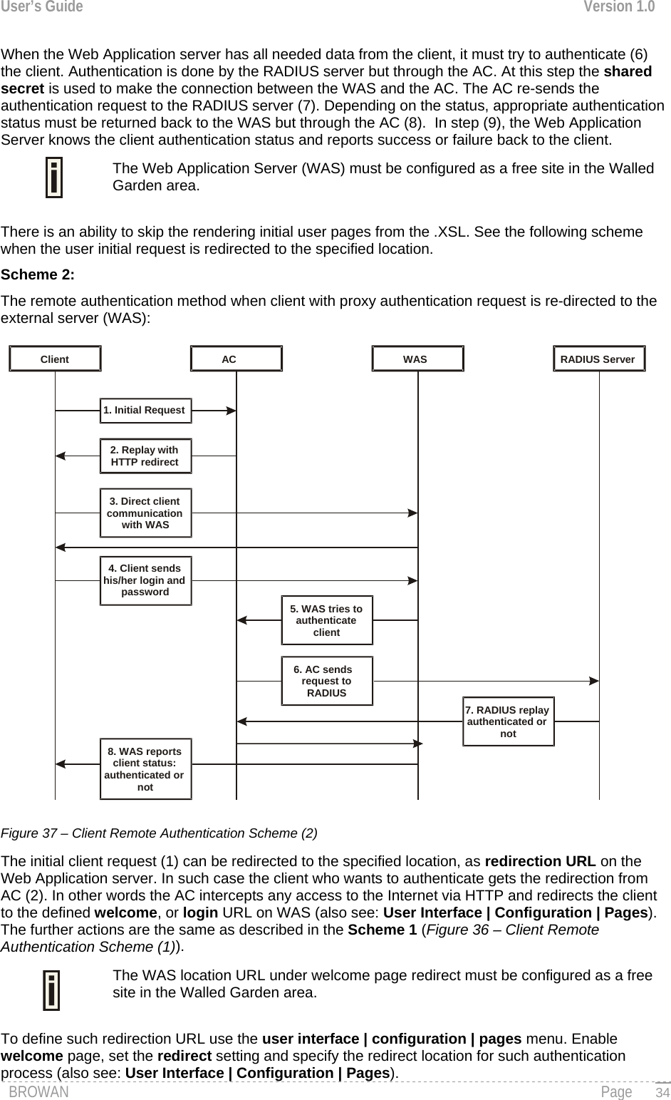
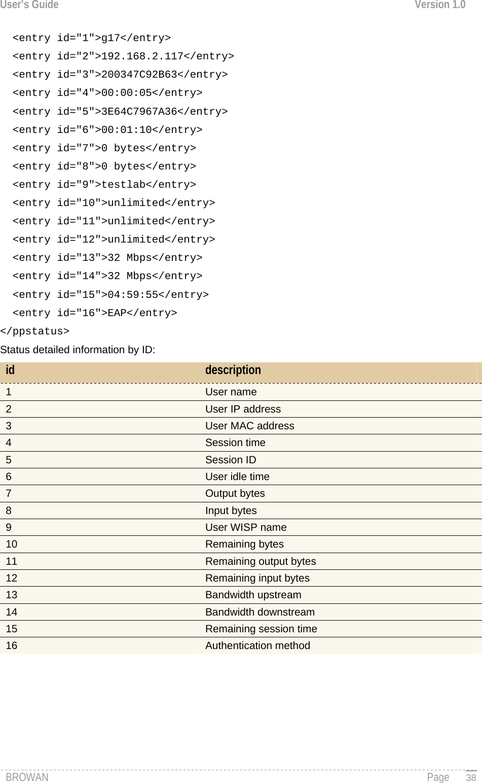
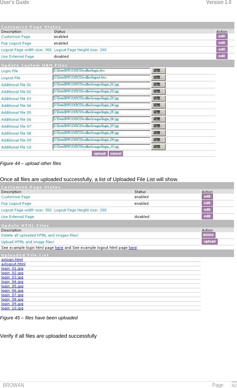
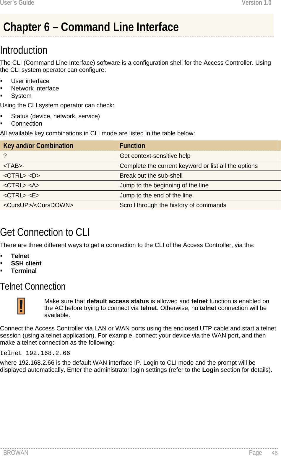
![User’s Guide Version 1.0 Figure 54 – Configure Network (1) Specific command contains several subcommands: network <command> <subcommand1> ?, (e.g. network radius servers ?) All available subcommands are displayed: Figure 55 – Configure Network (2) To get a list for available parameters on selected subcommand, type: network <command> <subcommand1> <subcommand2> ?, (e.g. network radius servers accounting ?) All available parameters on entered subcommand are displayed: Figure 56 – Configure Network (3) To configure the desired controller interface setting, type all required parameters with values and subcommands: network <command> <subcommand1> <subcommand2> [-parameter] <value> (e.g. network radius servers accounting 1 –a 127.0.0.2 –p 1814 –s testing111), where parameters are as follows: -a – RADIUS server IP address used for RADIUS accounting -p – RADIUS server port number used for RADIUS accounting -s – Shared secret key for accounting. Figure 57 – Configure Network (4) BROWAN Page 49](https://usermanual.wiki/GemTek-Technology/R950829G.Manual-Part-1/User-Guide-716069-Page-51.png)
![User’s Guide Version 1.0 User User is a category of commands that configures controller interface settings, affecting the user’s interface: redirection URL, free sites (walled garden), system management access, administrator login/password. A full list of all available user commands/subcommands and their parameters is available in the Appendix section: C) CLI Commands and Parameters. In general, the user command usage is as follows: user <command> <subcommand1> <subcommand2> [-parameter] <value> To get the full list of the user commands, type: user ? Figure 59 – User Commands List To get a list of all-available subcommands for a specific command, type: user <command> ?, (e.g. user walled_garden ?) All available subcommands for walled garden (free sites) are displayed: Figure 60 – Configure User Interface (1) To configure selected user interface settings, type: User <command> <subcommand1> <subcommand2> [-parameter] <value>, (e.g. user walled_garden url A -u www.gemtek-systems.com -s gemtek site), where parameters are as follows: A – action: add URL -u – define URL address -s – define URL description, visible for user: Figure 61 – Configure User Interface (2) If successful, a message regarding the successful completion is displayed; otherwise, an error message is displayed. BROWAN Page 51](https://usermanual.wiki/GemTek-Technology/R950829G.Manual-Part-1/User-Guide-716069-Page-53.png)
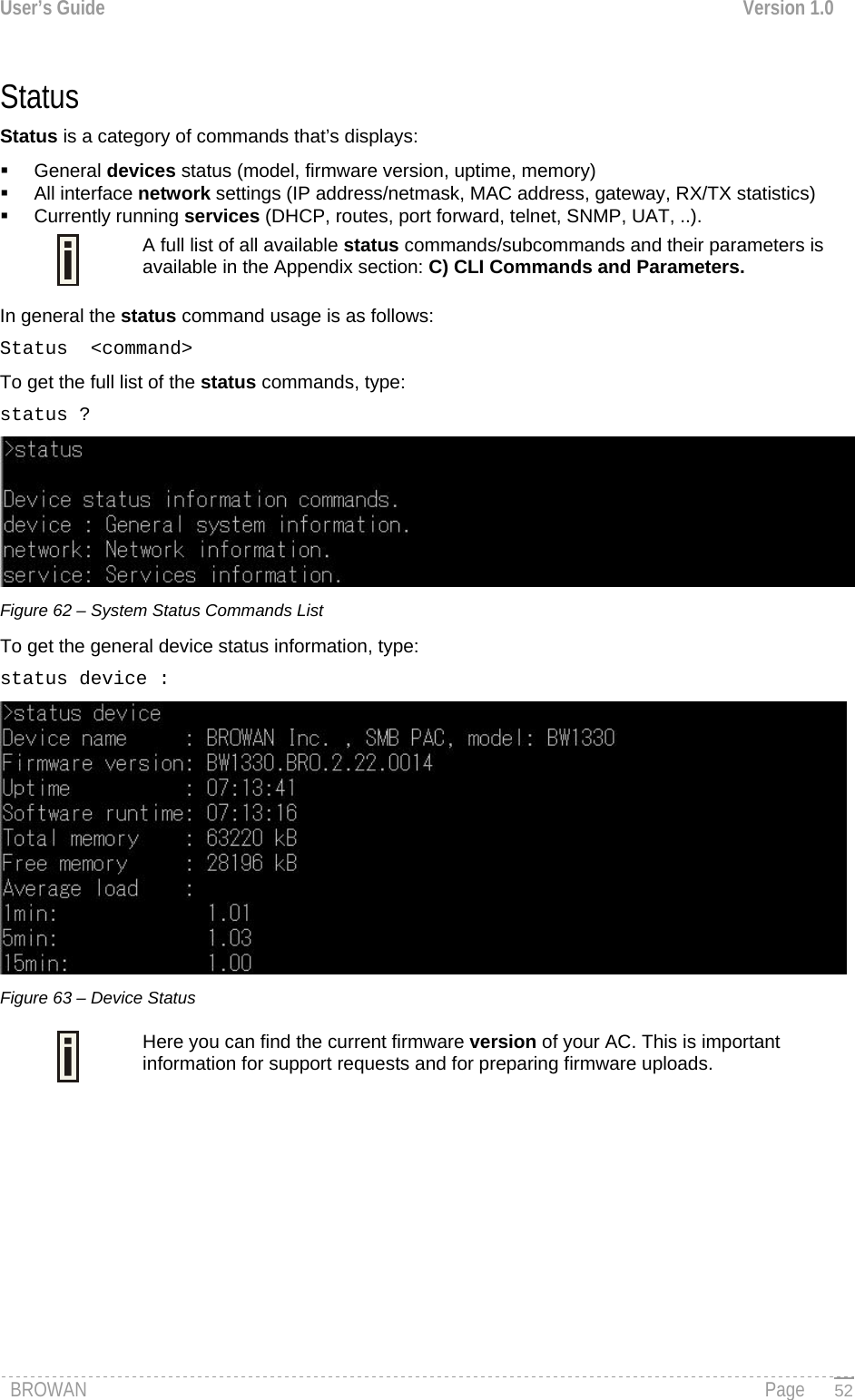
![User’s Guide Version 1.0 System System is a category of commands that configures access to controller (telnet, AAA methods, L2 isolation, SNMP, UAT) and configuration: clock, NTP, pronto, syslog, trace and firmware upgrade. A list of all available system commands/subcommands and their parameters are available in the Appendix section: C) CLI Commands and Parameters. In general, the system command usage is as follows: system <command> <subcommand1> <subcommand2> [-parameter] <value> To get the full list of the system commands, type: system Figure 64 – System Commands List Telnet To make a telnet connection, type the telnet command in the command line: telnet The telnet client is activated and ready for a telnet session. Figure 65 – Telnet Session Quit the telnet to return to CLI interface. Reboot To stop the controller and reboot the device, type the reboot command in the command line. No configuration changes are done. The last saved configuration is applied to the rebooted controller. Reset To reset the controller to factory defaults, type the reset command. The device is restarted and defaults values are set. Please note that even the administrator password will be set back to the factory default. Exit To leave the CLI mode, type the Exit command in the command line. BROWAN Page 53](https://usermanual.wiki/GemTek-Technology/R950829G.Manual-Part-1/User-Guide-716069-Page-55.png)

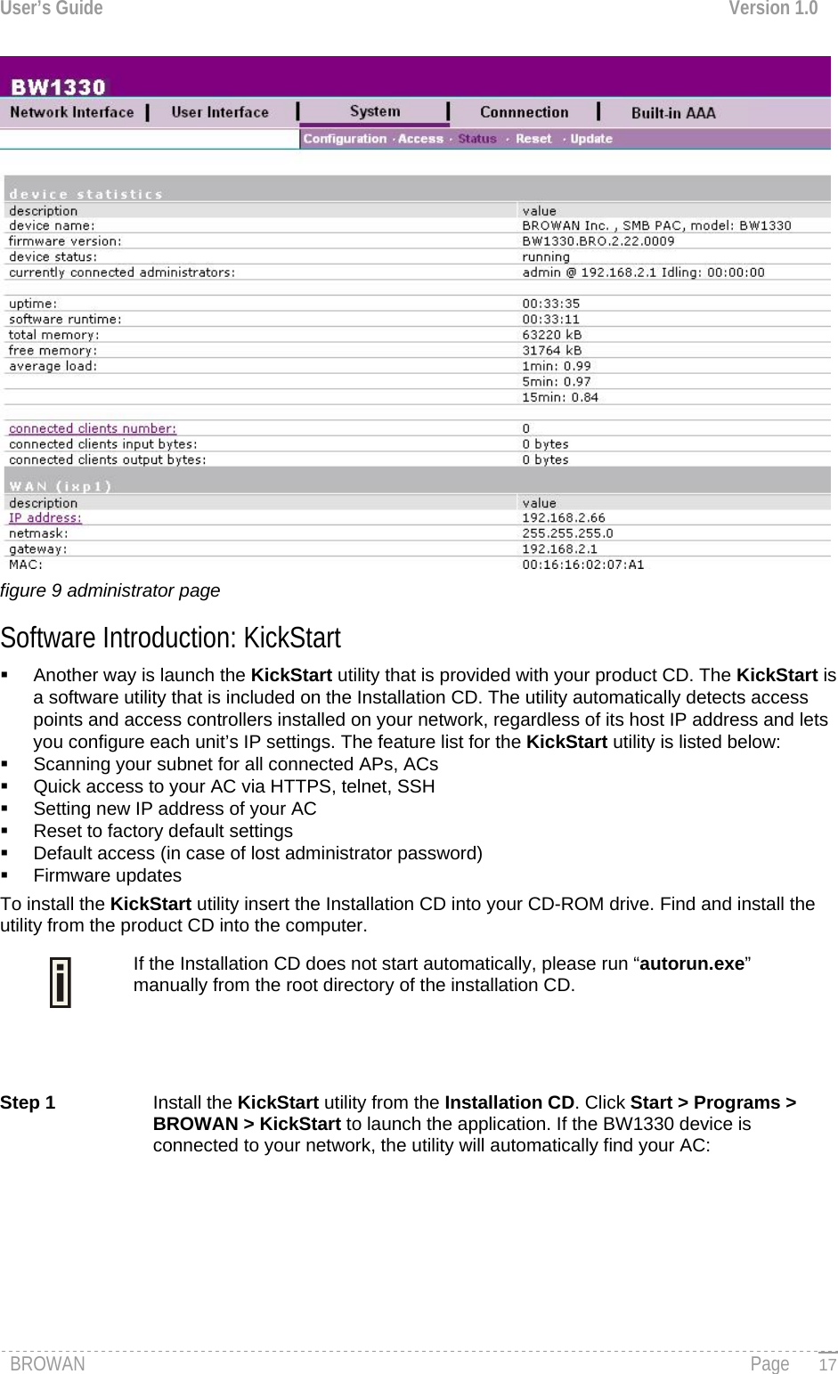
![User’s Guide Version 1.0 Network Interface Network Interface | Configuration | Interface Configuration The SMB Public Access Controller contains two multi-purpose network interfaces: br1 and ixp1. These interfaces can be configured to work as either local area network (LAN) or wide area network (WAN) interfaces or wireless area network(WLAN) for Access Points. LAN is used to connect hubs, switches, Access Points and subscribers. The WAN port connects to the Internet or the service provider’s backbone network. The wlan1_0 is the first virtual AP for wireless network. All these interfaces are listed in the interface configuration page. By default a bridge exists (labeled br1) which contains two interfaces: wlan1 and ixp0.All network interfaces available in the SMB Public Access Controller are shown in the following table: Figure 68 – Interface Configuration Table To change network interface configuration properties click the edit button in the action column. The status can be changed now: Figure 69 – Edit Interface Configuration Settings part.1 Interface - standard interface name. This name cannot be edited and is assigned by the operating system during startup. Interface name cannot be changed because the hardware drivers define it. Status – select the status of interface: [enabled/disabled]. Do not disable the interface through which you are connected to the BW1330. Disabling such interface will lose your connection to the device. Type – network type cannot be changed. There are two possible networking types: LAN – interface is used as local area network (LAN) gateway, and is connected to a LAN; WAN – interface is used to access the ISP network; Change status or leave in the default state if no editing is necessary and click the continue button. Then the following parameters can be changed: Figure 70 – Edit Interface Configuration Settings part.2 IP Address – specify new interface IP address [in digits and dots notation, e.g. 192.168.5.1]. IP address of each interface should be from a different subnet; otherwise, you will receive an error message. Netmask – specify the subnet mask [[0-255].[0-255].[0-255].[0-255]].These numbers are a binary mask of the IP address, which defines IP address order and the number of IP addresses in the subnet. BROWAN Page 59](https://usermanual.wiki/GemTek-Technology/R950829G.Manual-Part-1/User-Guide-716069-Page-61.png)
![User’s Guide Version 1.0 Gateway – interface gateway. For LAN type interfaces, the gateway can only be defined as WAN interface gateway. The gateway of the WAN interface is usually the gateway router of the ISP or other WAN network. [Default gateway is marked with ‘*’]. Update – update old values with entered ones. The DHCP server settings will be automatically adjusted to match the new network settings. Figure 71 – Apply or Discard Interface Configuration Changes Apply changes – to save all changes made in the interface configuration table at once. Discard changes – restore all previous values. For such general changes as interface settings change, the Wireless PAC server needs to be restarted. Request for restart server appears: Figure 71 – Restart Server Reboot – Click the button to restart the server and apply the changes. Network Interface | Configuration | Bridge A bridge transparently relays traffic between multiple network interfaces. This means that a bridge connects two or more physical LAN interfaces together to form one bigger (logical) network interface. There are some restrictions for bridge management that shall be taken into account: There is special bridge br1 in BW1330 that cannot be removed. This bridge initially contains two interfaces: wlan1_0 and ixp0. Interfaces (physical, VLAN or GRE tunnel) can be included only in one bridge. The WAN interface cannot be included into a bridge. VLAN's cannot be created on bridge interfaces they can only be added to them. A Bridge cannot be included into another bridge. By default the enabled bridge (ixp0 and wlan1_0) on br1 interface exists on the system: figure 72 - Default Bridge To set up bridge on the AC click edit button and enter following parameters: figure73 - setting parameters BROWAN Page 60](https://usermanual.wiki/GemTek-Technology/R950829G.Manual-Part-1/User-Guide-716069-Page-62.png)
![User’s Guide Version 1.0 Ageing – define the Ethernet (MAC) address ageing time, in seconds [0-65535]. The ageing time is the number of seconds a MAC address will be kept in the forwarding database after having received a packet from this MAC address. The entries in the forwarding database are periodically timed out to ensure they won't stay around forever. Default value is 0. Garbage – specify the interval in seconds between garbage collector runs [0-65535]. Garbage collector periodically checks MAC table for timed out entries and removes them from the table. Default value is 0. STP –define the STP (Spanning Tree Protocol) status [enabled/disabled]. Priority – define the bridge’s priority [high,medium,low]. Default value is low.Delay – specify the bridges’ forward delay time in seconds [0-65535]. Delay is the time spent in each of the Listening and Learning states before the Forwarding state is entered. Default value is 0.Hello Time – specify the interval between hello packets in seconds [0-65535]. Hello packets are used to communicate information about the topology throughout the entire Bridged LAN. Default value is 0. Max. Age – specify the maximum bridge message age in seconds [0-65535]. If the last received hello packet is more than this value, the bridge in question will initiate the Root Bridge election procedure. Default value is 0. Click continue button to finish the parameters setting and click new button if needs new interfaces adding into bridge. figure – 74 bridge setting Click new button to add interfaces into bridge and specify the bridge ports (interfaces): figure – 75 add interface Port (interface) – select the interface name to be bound into bridge . Cost – specify the port’s path cost on this interface. This value is used in the designated port and root port selection algorithms. Default value is low. Priority – specify the priority of ports with equal cost. You can use this to control which port gets used when there are redundant paths. If you want to remove interface from bridge click delete button. e.g remove ixp0 from bridge. Click delete button on the ixp0 column. BROWAN Page 61](https://usermanual.wiki/GemTek-Technology/R950829G.Manual-Part-1/User-Guide-716069-Page-63.png)
![User’s Guide Version 1.0 figure 76 – remove interface Click apply changes button and then reboot system to finish the removing. figure 77- apply and reboot Network Interface | Configuration | VLAN Up to 4094 VLANs can be created in the system. Virtual Local Area Networks (VLANs) are logical groupings of network resources. You can create your own VLANs on your AC using the network interface | configuration | VLAN menu. By default no VLANS are defined on the system: Figure 78 – VLAN To create a VLAN on the AC click the new button and enter following parameters: Figure 79 – Create New VLAN Interface – select interface for your VLAN network. VLANs cannot be created on a bridge. Status – non-editable, by default is disabled. ID – assign ID for your VLAN network [1 to 4094]. Client devices that associate using the ID are grouped into this VLAN. You can not create VLANs which interface includes in bridge such as ixp0.If you want to create VLANs on the interface ixp0 you must separate ixp0 from bridge(br1 interface) via network interface| configuration| Bridge menu. Refer to Chapter 8 Network Interface | Configuration | Bridge Please note after remove ixp0(LAN) it is DHCP server disabled as default.You will connect BW1330 either via WAN port(fix IP:192.168.2.66) or wlan1_0 wireless connected which DHCP server enabled(ip:192.168.3.x) as default. Other VLAN settings cannot be changed. Click on the disabled link to continue specifying settings for your VLAN. The network interface configuration page is opened and VLAN settings are ready for editing: BROWAN Page 62](https://usermanual.wiki/GemTek-Technology/R950829G.Manual-Part-1/User-Guide-716069-Page-64.png)
![User’s Guide Version 1.0 Figure 80 – Configure VLAN Status – enable/disable your VLAN network. Select [enable] and click the continue button to configure the VLAN settings: Figure 81 – Configure VLAN Type – cannot be edited, depends on selected interface for VLAN [ixp0]. IP Address – enter the network address of your VLAN [format: digits and dots]. Netmask – enter the netmask for your VLAN network [format: digits and dots]. Gateway – select gateway for VLAN network [default: ixp1]. Click the update and restart and apply changes to save your new VLAN. Check the interface | configuration | VLAN menu for new created VLAN: Figure 82– Enable New VLAN Network Interface | Configuration | Route Under the network interface | configuration | route menu, static routes for the Ethernet interfaces can be set. By default no static routes are defined on the system: Figure 83 – Route A routing rule is defined by the target subnet (target IP address and subnet mask), interface and/or gateway where to route the target traffic. A data packet that is directed to the target network is routed to the specified AC interface or to another gateway router. To add a new static route for the system, click the new button under the action column and specify the following parameters: Figure 84 – Add New Route If you want to set static routes on the interface ixp0 you must separate ixp0 from bridge (br1 interface). Refer to Chapter 8 Network Interface | Configuration | Bridge BROWAN Page 63](https://usermanual.wiki/GemTek-Technology/R950829G.Manual-Part-1/User-Guide-716069-Page-65.png)
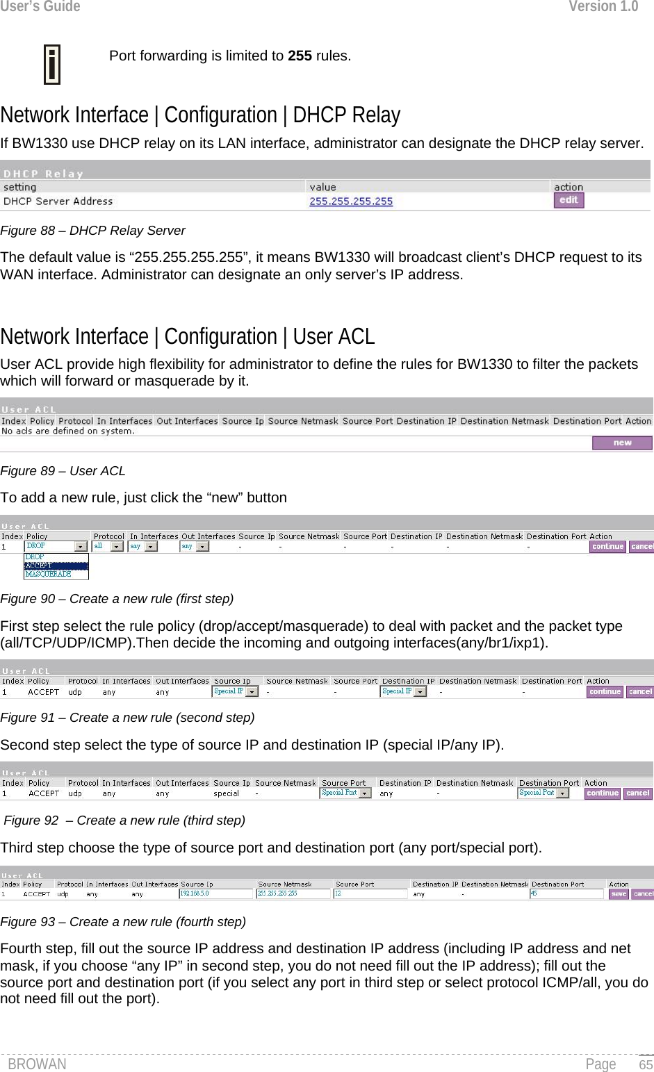
![User’s Guide Version 1.0 Interface – choose device interface for the route: [br1/ixp0/ixp1/vlan[n]]. Status – set new static route status: [enabled/disabled]. Gateway – enter the gateway address for the route. 0.0.0.0 stands for the default gateway of the selected interface [IP address]. Target IP Address – enter network address or host IP to be routed to [IP address]. Netmask – enter the target network netmask [dots and digits]. Save – save the new route. Cancel – restore all previous values. Figure 85 – Save New Route Up to 255 static routes can be set between each interface. Network Interface | Configuration | Port Forwarding Port Forwarding is required when NAT is configured. NAT translates all internal addresses to one official IP address (WAN IP address). With port forwarding enabled it is possible to access internal services and workstations from the WAN interface. Port forwarding forwards TCP or UDP traffic trough the BW1330 controller’s local port to the specified remote port. Use the network interface | configuration | port forwarding menu to specify such a port forwarding rule. By default no port forwards are defined on the controller: Figure 86 – Port Forwarding Rules Click the new button to add a port-forwarding rule: Figure 87 – Add Port Forwarding Rule. Status – select status: [enabled/disabled]. Type – select type of forwarding traffic: [TCP/UDP]. Local IP Address – BW1330 device interface address from which the selected traffic should be forwarded. Local Port –BW1330 device interface port from which the selected traffic should be forwarded. Remote IP Address/Port – internal IP address and port no (LAN ports) to which the selected traffic shall be forwarded. Example: Create rule as follow: Type = TCP, local IP address/port = 192.168.2.248:8080 remote IP address/port = 1.2.3.4:8080. With such a rule all traffic coming to port 8080 on the BW1330 interface local address 192.168.2.248 will be forwarded to port 8080 on the server (host) 1.2.3.4. BROWAN Page 64](https://usermanual.wiki/GemTek-Technology/R950829G.Manual-Part-1/User-Guide-716069-Page-66.png)
![User’s Guide Version 1.0 Figure 94 – Create a new rule (fifth step) After complete the rule configuration, click the “apply changes” button to save your configuration, You can also re-order your rules if you have many rules configured and arrange the priority of them. The rule with index 1 has the highest priority; with index 2 has the second high priority and so on. Click the “sort” button to change the index. Figure 95 – re-order rules Click the “sort” button of one rule to re-order its priority and then select the index number; click “save” button to save your changes. Network Interface | Configuration | Management Subnet Each network interface can have a management subnet. Use the network interface | configuration | management subnet menu to configure this feature on selected interface. When management subnet is enabled, port forwarding will NOT WORK when connecting from IP addresses that are in the management subnet's remote administrator's network. This is because the management subnet allows connecting to the client computer without using port forwarding. The administrator can enable or disable management subnet for each interface. By default no management subnet is enabled on the controller: Figure 96 – Management Subnet To specify new subnet management click the edit button on the selected interface: Figure 97 – Add Management Subnet IP Address and Netmask – specify the IP address and netmask of the management subnet. IP address will be set on the network interface as an alias, so you can connect to the BW1330 using this address. This IP address should be used on access points as the gateway address. Remote Network and Netmask –specify the remote network that is allowed to access the local management subnet. Only addresses that are from the remote network will be accepted [dots and digits]. If you do not specify any remote network all stations with IP addresses from the management LAN are routed to the WAN port even without being authenticated. BROWAN Page 66](https://usermanual.wiki/GemTek-Technology/R950829G.Manual-Part-1/User-Guide-716069-Page-68.png)
![User’s Guide Version 1.0 Clients using an IP address from the management subnet can browse the Internet without authorization, and no accounting will be done. Thus, it is strongly recommended to allow traffic only from the administrative remote network (no 0.0.0.0/0.0.0.0 in remote specification). Example: Interface configuration for ixp0: type: LAN IP address: 192.168.3.1 netmask: 255.255.255.0 gateway: ixp1 Management subnet on ixp0: IP address: 10.0.0.1 netmask: 255.255.255.0 remote network: 10.10.0.1 remote netmask: 255.255.255.0 With these settings applied, the administrator will be able to connect to devices behind the BW1330 on interface ixp0, if these devices use address in the range: 10.0.0.2 ... 10.0.0.254. The administrator is connecting via the Internet (from ixp1 interface). The administrator’s computer can have an address from 10.10.0.1 to 10.10.0.254. Please note that devices which are using 10.0.0.2. – 10.0.0.254 addresses have access to the administrative network too! In this example, the administrative network uses the reserved IP address (10.x.x.x) – they are not routed in the Internet, so the administrator should setup routers in a path between the BW1330 and the administrator's computer to recognize 10.x.x.x addresses and route them correctly. This is not comfortable and sometimes it is impossible. There is a solution – the administrator can use GRE tunnel(see: Network Interface | Tunnels) to setup a tunnel between the administrator's computer and the BW1330. The only addresses visible on the Internet will be the BW1330 WAN IP address and the administrator's computer (or router) IP address. Network Interface | DNS DNS (Domain Name Service) service allows AC subscribers to enter URLs instead of IP addresses into their browser to reach the desired web site. Figure 98 –- DNS Settings Configuration You can enter the primary and secondary DNS servers settings under the network interface | DNS menu. Figure 99–Edit DNS Redirection Settings The DNS server or DNS address can be obtained dynamically if DHCP, PPPoE (for DSL) service is enabled. To add DNS server manually click the edit button in the action column and type in the DNS server’s IP address: IP address – enter the primary or secondary DNS server’s IP address [in digits and dots notation]. Save – click to save the new DNS server’s settings. BROWAN Page 67](https://usermanual.wiki/GemTek-Technology/R950829G.Manual-Part-1/User-Guide-716069-Page-69.png)
![User’s Guide Version 1.0 Network Interface | DHCP The BW1330 controller can act as a DHCP server and/or as a DHCP relay gateway. The DHCP (Dynamic Host Configuration Protocol) service is supported on the LAN interfaces [ixp0/vlan[n]]. This service enables clients on the LAN to request configuration information, such as an IP address, from a server. This service can be viewed in the following table: Figure 100 – DHCP Configuration By default the AC is configured to act as a DHCP server. Each LAN interface runs a different instance of the DHCP service. This service is configured by defining an IP address range and WINS address for client workstations. Other settings, such as the default gateway and DNS server address are configured automatically according to the interface settings. To see the complete DHCP service configuration, click the details button in the action column: Figure 101 – DHCP Settings Details To edit the DHCP service configuration [DHCP server/DHCP relay], click the edit button in the action column: Figure 102 – Edit DHCP Configuration Settings Status – select status from drop-down menu: Disabled – disable the DHCP service on the selected interface DHCP Server – enabled by default DHCP Relay – to route DHCP through the external server, enable relay service Case 1 Configure the DHCP server Select the interface on which you want to configure the DHCP service. Select the DHCP server and click the update button specify the DHCP server parameters: BROWAN Page 68](https://usermanual.wiki/GemTek-Technology/R950829G.Manual-Part-1/User-Guide-716069-Page-70.png)