GemTek Technology U910327 11 Mbps Wireless mini USB Module User Manual WL 383F Manual
Gemtek Technology Co., Ltd. 11 Mbps Wireless mini USB Module WL 383F Manual
UserManual.wiki
>
GemTek Technology
>
U910327 User Manual
Users Manual
Navigation menu
Upload a User Manual
Namespaces
Wiki Guide
HTML
PDF
Info
Views
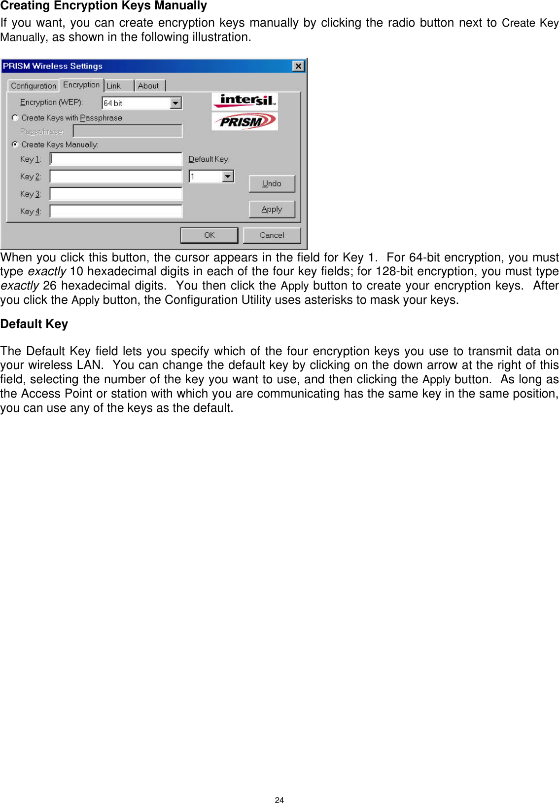
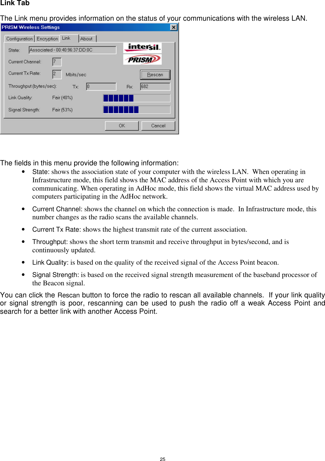
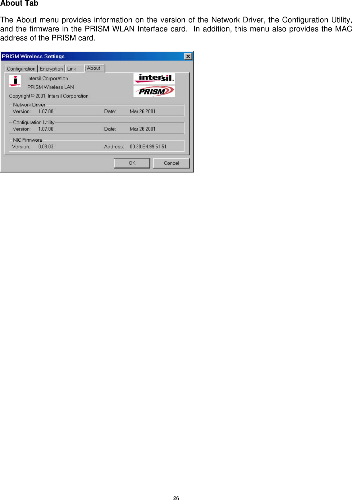
User Manual
Discussion / Help
Navigation