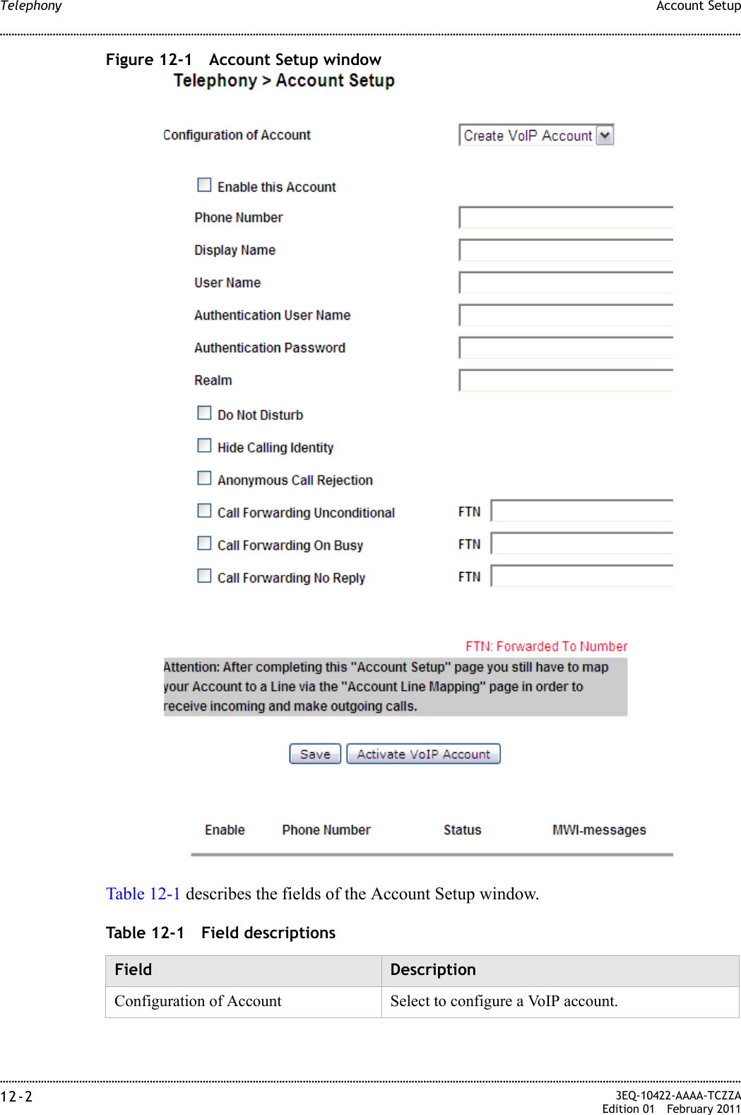
GemTek Technology WADB132GN 7130 Residential Gateway 6Vz/e.A4111 User Manual 6Ve z A4111 UG
Gemtek Technology Co., Ltd. 7130 Residential Gateway 6Vz/e.A4111 6Ve z A4111 UG
UserManual.wiki
>
GemTek Technology
>
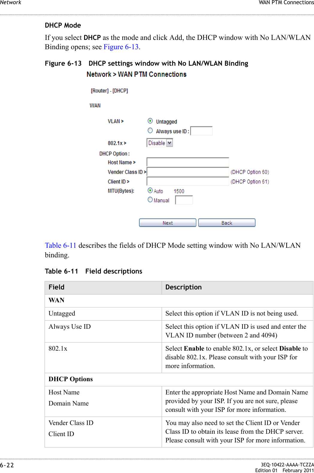
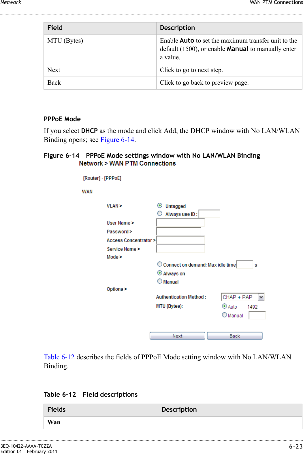
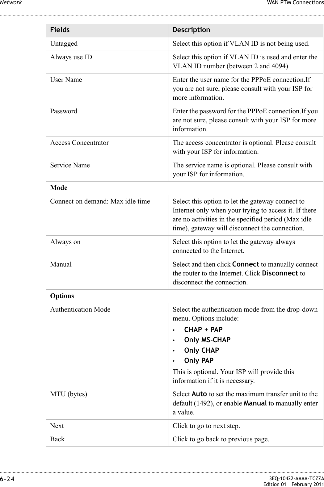
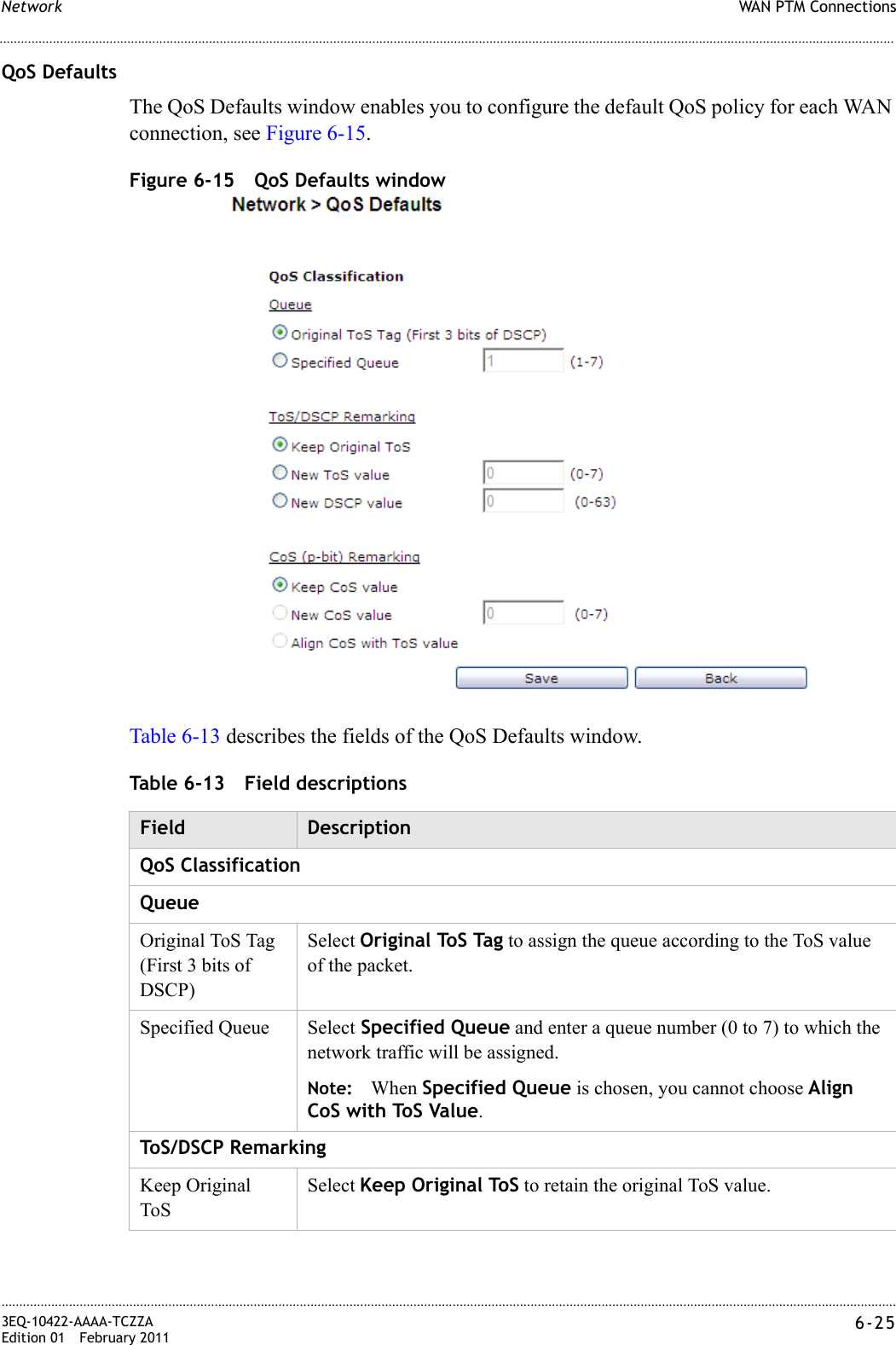
WADB132GN User Manual
User Manual
Navigation menu
Upload a User Manual
Namespaces
Wiki Guide
HTML
PDF
Info
Views
User Manual
Discussion / Help
Navigation