GemTek Technology WIXS-181 WiMAX Outdoor CPE User Manual WIXS 181 Quick Installation Guide
Gemtek Technology Co., Ltd. WiMAX Outdoor CPE WIXS 181 Quick Installation Guide
User manual rev
WIXS-181 Quick Installation
Guide

This Quick Installation Guide is intended for experienced installers.
Package Content
Check that the package contains:
ODU(Outdoor unit)
PoE(Power Over Ethernet) and Power plug
RJ45 CABLE CONNECTOR ASS'Y
Pole mounting kit
Additional Equipment and Tools required for Installation
PoE-to-outdoor Category 5E Ethernet cable with two shielded RJ-45 connectors and an RJ-45 connectors
crimping tool.
Mains plug adapter or termination plug (if the power plug on the supplied AC power cord does not fit local
power outlets).
WARNING:
ONLY experienced installation professionals who are familiar with local building and safety codes
and, wherever applicable, are licensed by the appropriate government regulatory authorities
should install outdoor units. Failure to do so may void the product warranty and may expose the
end user or Service Provider to legal and financial liabilities. The manufacturer and its resellers or
distributors are not liable for injury, damage or regulation violations associated with the installation
of outdoor units or antennas.
Equipment Location Guidelines
Select the optimal locations for the equipment using the following guidelines:
1. The antenna should provide a direct, or near line of sight, with the Base Station antenna. The higher the
placement of the antenna, the better the achievable link quality. The location of the ODU should enable easy
access to the unit for installation and testing.
2. The PoE should be installed as close as possible to the location where the PoE-to-outdoor cable enters the
building. The location of the PoE should be selected taking into account its connection to a power outlet and
the end-user’s data equipment. (The length of the POE-to-ODU cable, together with the length of the cable
connecting the POE to the data equipment, should not exceed 100m).
ODU Installation
Mounting the ODU
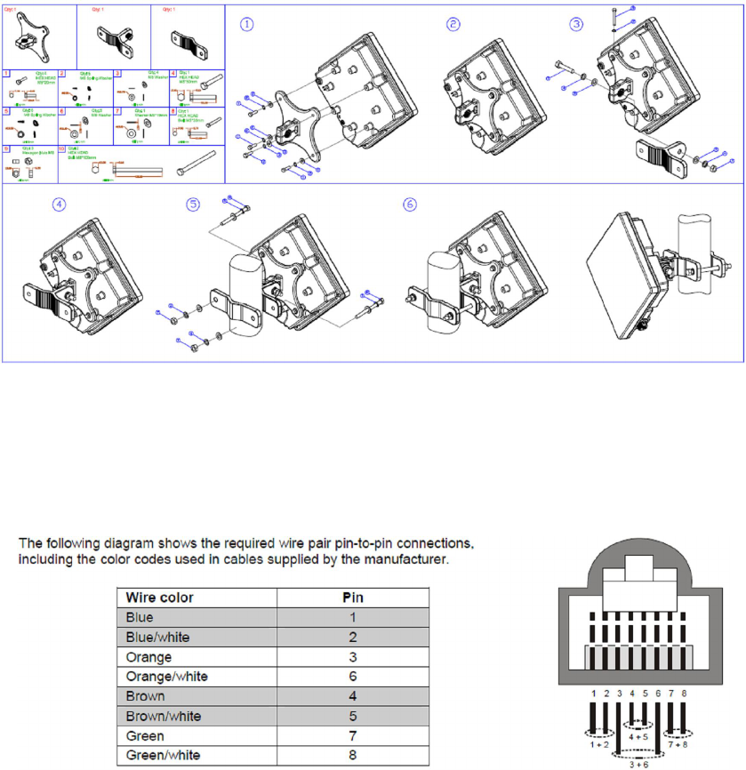
Mount the ODU unit using the supplied kit:
Preparing the PoE-ODU Cable
Use a crimp tool for RJ-45 connectors to prepare the wires. Insert them into the appropriate pins and use the tool
to crimp the connector. Make sure to do the following:
Remove as small a length as possible of the external jacket. Verify that the external jacket is well inside the
sealing cover when connected to the unit, to ensure good sealing.
Pull back the shield drain wire before inserting the cable into the RJ-45 connector, to ensure a good
connection with the connector's shield after crimping.
Connecting the PoE-ODU Cable
1. Follow the detailed instructions supplied with the sealing cap to assemble the sealing cap onto the cable: Strip
the cable sheath. Insert the screw nut into the housing. Insert the seal at the back end of the housing. Insert
the cable all the way through. Crimp the RJ-45 plug. Insert the plug into the housing. Then secure the sealing
nut in place. Stricken the gasket on the front end of the housing.
2. Connect the Ethernet cable to the RJ-45 connector of the ODU.
3. Use appropriate sealing material to protect the connection against moisture and humidity. Use high quality
sealing material such as Scotch® 130C Linerless Rubber Splicing Tape from 3M to ensure IP-67 compliant
protection against dust and water.
4. Route the cable to the location selected for the PoE.
5. Assemble an RJ-45 connector with a protective cover on the PoE end of the POE-ODU cable. Refer to the pin
assignment and color codes in standard cables described below.
PoE Installation
1. The unit can be placed on a desktop or a shelf. Alternatively, it may be wall-mounted.
2. Connect the PoE-ODU cable to the DATA & POWER OUT port.
3. Connect the PoE to the AC mains.
4. Connect ETHERNET port to a PC/Hub/Switch.
Basic Configuration
1. Use the Web Configuration Server to configure the basic parameters.
2. Connect a PC/Notebook to the POE.
3. By default, the CPE enables a DHCP server and computers or network devices connected to a LAN port to
automatically get an IP address from the CPE. If the CPE's DHCP server is disabled, you can set the IP
address, netmask, and gateway manually using the following parameters: IP address: 10.1.1.x, 1 < x < 253;
Netmask: 255.255.255.0; Gateway: 10.1.1.254.
4. Open a web browser, and connect to http:// 10.1.1.254/. The Login page is displayed. Enter the user name:
admin, password: admin and click Login.
5. Configure the parameters, as needed.
6. Reset the unit to apply the changes.
Aligning the ODU's Antenna
1. Point the ODU toward the general direction of the serving BS.
2. Verify that the unit is synchronized with a BS. If the unit is not synchronized with a BS, ensure that all
parameters are configured properly. If the unit is still not synchronized with a BS, improve the quality of
the link by changing the direction of the ODU or by placing the ODU at a higher or in an alternate
location.
3. Ensure that the front of the ODU is always facing the location of the BS. However, in certain conditions,
such as when the line of site to the BS is hampered, better reception may be achieved using a
reflected signal. In this case, the ODU is not always directed toward the BS.
4. Secure the unit firmly to the pole.
Verifying Proper Operation
Verify data connectivity by pinging the BS or by connecting to the Internet.
Federal Communication Commission Interference Statement
This equipment has been tested and found to comply with the limits for a Class B digital device, pursuant to Part
15 of the FCC Rules. These limits are designed to provide reasonable protection against harmful interference in a
residential installation. This equipment generates, uses and can radiate radio frequency energy and, if not
installed and used in accordance with the instructions, may cause harmful interference to radio communications.
However, there is no guarantee that interference will not occur in a particular installation. If this equipment does
cause harmful interference to radio or television reception, which can be determined by turning the equipment off
and on, the user is encouraged to try to correct the interference by one of the following measures:
- Reorient or relocate the receiving antenna.
- Increase the separation between the equipment and receiver.
- Connect the equipment into an outlet on a circuit different from that to which the receiver is connected.
- Consult the dealer or an experienced radio/TV technician for help.
FCC Caution: Any changes or modifications not expressly approved by the party responsible for compliance could
void the user's authority to operate this equipment.
This device complies with Part 15 of the FCC Rules. Operation is subject to the following two conditions: (1) This
device may not cause harmful interference, and (2) this device must accept any interference received, including
interference that may cause undesired operation.
IMPORTANT NOTE:
Radiation Exposure Statement:
This equipment complies with FCC radiation exposure limits set forth for an uncontrolled environment. This
equipment should be installed and operated with minimum distance cm between the radiator & your body.
This transmitter must not be co-located or operating in conjunction with any other antenna or transmitter.
The availability of some specific channels and/or operational frequency bands are country dependent and are
firmware programmed at the factory to match the intended destination. The firmware setting is not accessible by
the end user.
Due to the essential high output power natural of WiMAX device, use of this device with other transmitter at the
same time may exceed the FCC RF exposure limit and such usage must be prohibited (unless such co-
transmission has been approved by FCC in the future).
29