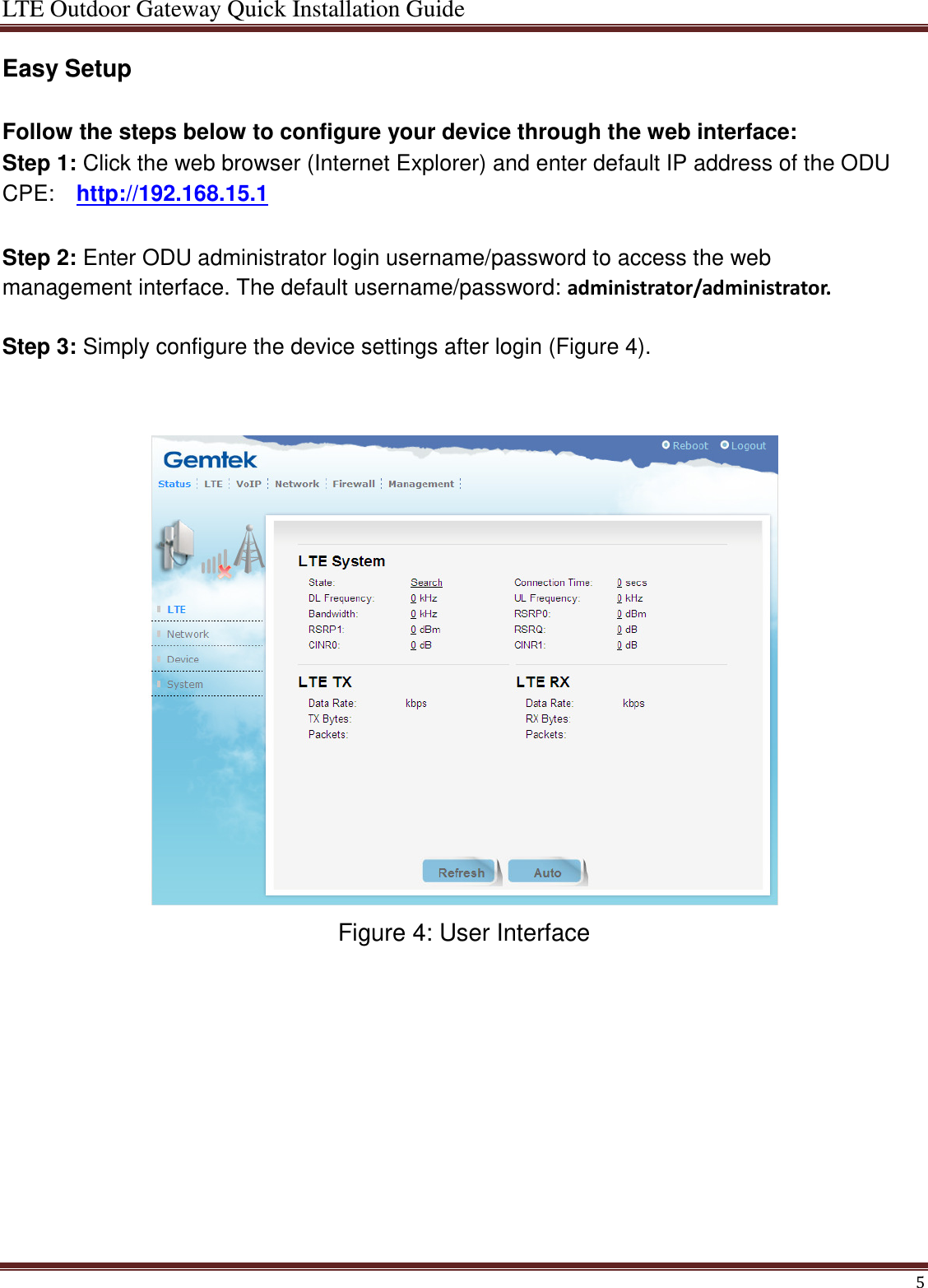
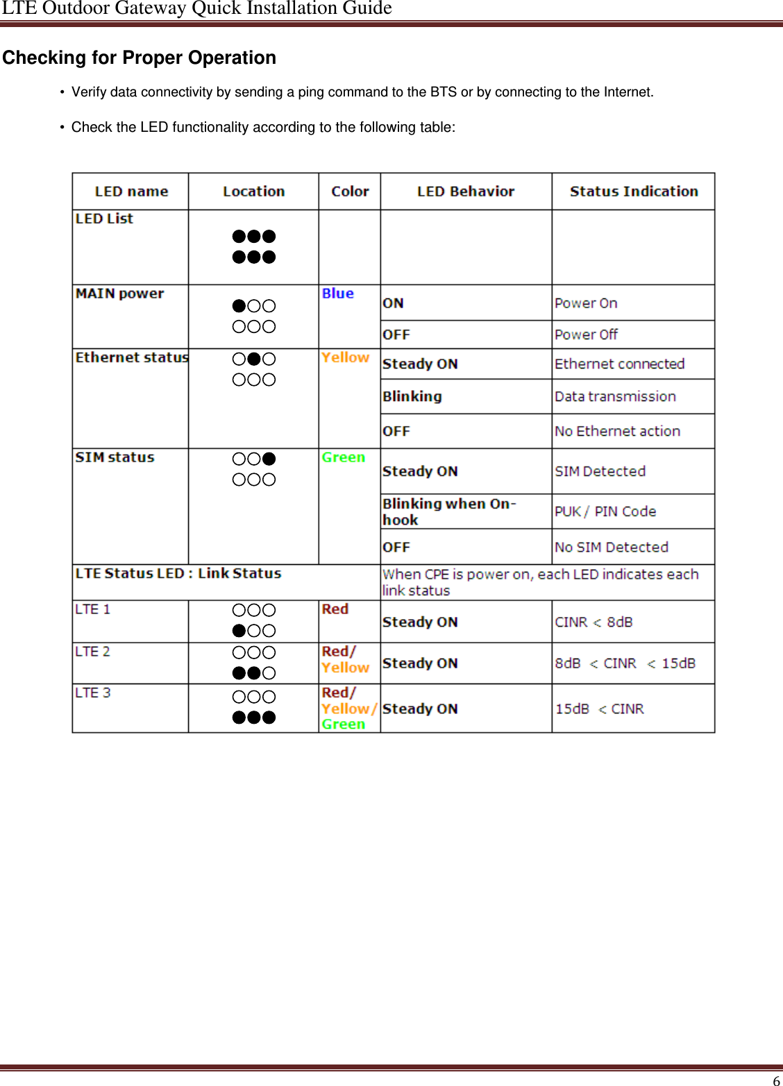
GemTek Technology WLTCS105 Band 41 TD-LTE Outdoor CPE User Manual LTE Outdoor Gateway Quick Installation Guide

Gemtek Technology Co., Ltd. Band 41 TD-LTE Outdoor CPE LTE Outdoor Gateway Quick Installation Guide

User manual

LTE Outdoor Gateway Quick Installation Guide  Introduction  This Quick Installation Guide covers the basic installation of the LTE Outdoor Gateway.    Overview The LTE Outdoor Gateway is a LTE subscriber station designed to provide Internet access for a home or small office. The LTE Outdoor Gateway includes an outdoor unit (ODU) connected to a supply unit (IDU). The ODU provides the LTE Internet link, and the IDU serves as the gateway for a local Ethernet wired.  The indoor unit includes:  •  One standard RJ-45 Ethernet port for LAN connections.    •  One 8 PIN RJ-45 Ethernet port for connection to the ODU. This cable provides a dedicated Power-over-Ethernet (PoE) power supply to the ODU, as well as a data link between the ODU and the IDU. The IDU should be connected to an AC power connection.       Installing the ODU  Before installing the ODU, verify that you have all the items listed in the package checklist. If any of the items are missing or damaged, contact your LTE service provider.    Selecting a Location  The ODU should be pole-mounted outdoors and aligned so its antenna faces the nearest LTE base station. When selecting a suitable location for the unit, consider these guidelines:  •  Place the ODU as high as possible to achieve the best possible link quality.    •  Place the ODU away from power and telephone lines.    •  Avoid placing the ODU too close to any metallic reflective surfaces.    •    Be sure to ground the ODU with an appropriate grounding wire (not included) by attaching it to the grounding screw on the unit and to a good ground connection.           1
LTE Outdoor Gateway Quick Installation Guide  Additional information:  Check below items before installing the outdoor CPE: •  One RJ-14 connector for connecting to the telephone line. •  One RJ-45 connector for connecting to the PoE adaptor. •  LED indicator inside and SIM card slot for inserting SIM card. •  A grounding screw on the rear panel.                    Mounting the ODU Mount the ODU unit on a 1"-4" pole using the supplied kit (Figure 1), or the optional Tilt accessory.  Using the Clamp  1  Thread the M10*100mm bolt through a spring washer, flat washer and the bracket holes.   2  With the connector facing downward, attach the ODU to a 1" -4" pole.   3  Attach the bracket to the other side of the pole.   4  Thread the M10*100 mm bolts through both holes on either side. Tighten the nuts.    Figure 1: Mounting the ODU on the Pole    2
LTE Outdoor Gateway Quick Installation Guide  Installing the IDU The IDU can only be mounted indoors. It should be mounted on any horizontal surface, such as a desktop or shelf. Be sure to select a suitable location for the device within 100 m (328 ft.) of the ODU. Consider these guidelines:  •  Select a cool, dry place, which is out of direct sunlight.   •  The device must be near an AC power outlet that provides 100 to 240 V, 50 to 60 Hz with proper grounding.   •  The device should be accessible for network cabling.   •  The overall length of the Ethernet cables from the ODU to the IDU and from the IDU to the PC must not exceed 100m. You must plan a cable route from the ODU to the IDU indoors. Consider these guidelines:    •  Determine a building entry point for the cable.   •  Determine if conduits, bracing, or other structures are required for safety or protection of the cable.   •   For additional lightning protection, it is recommended to use a lightning arrestor immediately before the Ethernet cable enters the building.  Connecting the Cables  Figures 2 demonstrates ODU CPE connected to an IDU (supply unit –PoE) RJ-45 and telephone line have to be connected to LTE outdoor CPE.  •  Follow the instruction on PoE adapter: RJ-45 port (“TO/FROM OSU POE RJ45) connects to ODU through RJ-45 cable, meanwhile, RJ-14 port (“TO/FROM OSU VOIP) and outdoor CPE can be connected by telephone line.   •  Using a phone line connected the telephone with RJ-11 port on POE adapter. •  Available for other device such as PC/Hub/Switch connected to PoE through RJ-45 cable on PoE.              Figure 2:CPE Connections     Connect the indoor unit to the AC mains using the power adapter supplied with the unit. Do not connect the data equipment to the PoE port on the IDU, as it supplies DC power to the ODU, and this may harm other equipment connected to it.  CAUTION  !   3
LTE Outdoor Gateway Quick Installation Guide  Preparing and Connecting the IDU-ODU Cable  Use only Category 5E 4x2x24# FTP outdoor cables from an approved manufacturer. The cable provides pin-to-pin connection on both ends.  1    Prepare the cable: Use a crimp tool for RJ-45 connectors to prepare the wires. Insert them into the appropriate pins and use the tool to crimp the connector. Make sure to do the following:  » Remove as small a length as possible of the external jacket. Verify that the external jacket is well inside the sealing cover when connected to the unit, to ensure good sealing.    » Pull back the shield drain wire before inserting the cable into the RJ-45 connector, to ensure a good connection with the connector's shield after crimping.    2     Connect the cable (see Figure 3):  a  Remove the sealing gland plug from the gland nut.    b  Open the sealing gland nut and remove it. Do not disassemble the gland base from the bracket.    c  Insert the cable into the sealing gland base and connect it to the RJ-45 connector at the bottom of the ODU, labeled. Make sure that the connector is completely inserted and tightened.    d  Insert the rubber bushing on the cable into the gland base.          Figure 3 : Cable Insertion   4
LTE Outdoor Gateway Quick Installation Guide  Easy Setup  Follow the steps below to configure your device through the web interface:   Step 1: Click the web browser (Internet Explorer) and enter default IP address of the ODU CPE:    http://192.168.15.1  Step 2: Enter ODU administrator login username/password to access the web management interface. The default username/password: administrator/administrator.  Step 3: Simply configure the device settings after login (Figure 4).    Figure 4: User Interface             5
LTE Outdoor Gateway Quick Installation Guide  Checking for Proper Operation  •  Verify data connectivity by sending a ping command to the BTS or by connecting to the Internet.    •  Check the LED functionality according to the following table:                   6
LTE Outdoor Gateway Quick Installation Guide  Federal Communication Commission Interference Statement This device complies with Part 15 of the FCC Rules. Operation is subject to the following two conditions: (1) This device may not cause harmful interference, and (2) this device must accept any interference received, including interference that may cause undesired operation. This equipment has been tested and found to comply with the limits for a Class B digital device, pursuant to Part 15 of the FCC Rules.  These limits are designed to provide reasonable protection against harmful interference in a residential installation. This equipment generates, uses and can radiate radio frequency energy and, if not installed and used in accordance with the instructions, may cause harmful interference to radio communications.  However, there is no guarantee that interference will not occur in a particular installation.    If this equipment does cause harmful interference to radio or television reception, which can be determined by turning the equipment off and on, the user is encouraged to try to correct the interference by one of the following measures: -  Reorient or relocate the receiving antenna. -  Increase the separation between the equipment and receiver. -  Connect the equipment into an outlet on a circuit different from that to which the receiver is connected. -  Consult the dealer or an experienced radio/TV technician for help.  FCC Caution: Any changes or modifications not expressly approved by the party responsible for compliance could void the user's authority to operate this equipment. This transmitter must not be co-located or operating in conjunction with any other antenna or transmitter. Radiation Exposure Statement: This equipment complies with FCC radiation exposure limits set forth for an uncontrolled environment. This equipment should be installed and operated with minimum distance 24 cm between the radiator & your body.    7

Navigation menu