Genvict Technologies WB-L20B DSRCS OBU User Manual
Shenzhen Genvict Technologies Co.,Ltd DSRCS OBU Users Manual
Contents
- 1. Users Manual
- 2. User Manual
Users Manual

Cooperative Vehicle Infrastructure (V2X) Specific
On-board Equipment WB-L20B
User Guide

WB-L20B User Guide
1
Catalog
I.Product Profile ......................................................................................................................... 2
1.1 Product Features ..................................................................................................................... 2
1.2 Communication Interface ....................................................................................................... 2
II.Equipment Installation ............................................................................................................ 2
2.1 Access toWB-L20B ................................................................................................................ 6
2.2 Log-in WB-L20B ................................................................................................................... 6
2.2.1 By serial port ....................................................................................................................... 6
2.2.2 By Wi-Fi ......................................................................................................................... 6
III.WB-L20B Automatic Start-up Items ....................................................................................... 7
IV.WB-L20B Software Use Guidance ......................................................................................... 8
4.1 Device Network Interface Introduction ................................................................................. 8
4.2Wi-Fi Use Guidance ................................................................................................................ 9
4.2.1 Modify Wi-Fi IP Address and Assign IP Address Pool .................................................. 9
4.3Ethernet Use Guidance .......................................................................................................... 10
4.3.1 ManuallyConfigure Ethernet Interface IP Address ...................................................... 10
4.3.2 AutomaticallyAcquire Ethernet Interface IP Address .................................................. 11
4.4 4G Network Interface Use Guidance ................................................................................. 11
4.5 System Upgrading Introduction ........................................................................................... 11
4.5.1 Upgrading File Preparation .......................................................................................... 11
4.5.2 Parameter Introduction ........................................................................................... 12

WB-L20B User Guide
2
I. Product Profile
WB-L20B on-board unit is the equipment dedicated in cooperative intelligent transportation (V2V, V2I,
V2X) based on 5.855 ~ 5.925GHz DSRC technology, providing DSRC (IEEE802.11 p), Bluetooth,
Wi-Fi, Bluetooth, Ethernet and CAN interfaces in connected vehicle. It is mainly used in collaborative
transportation, trafficsafety and automatic driving applications. WB-L20B is a class C device
according to Table 9 of ASTM E2213-03 and is for private application.
1.1 Product Features
DSRC standard supported
Comply with IEEE 802.11p, IEEE1609.X, SAE-J2735 protocol/standard
Provide user development package WB - SDK1.0
Working frequency: 5.855 GHz ~ 5.925 GHz
Transmission rate: 3 ~ 27 Mbps
1.2 Communication Interface
DSRC1/DSRC2 antenna interface, Wi-Fi interface
GPS antenna interface, USB2.0 interface
RS232/CAN interface, Ethernet RJ45 interface
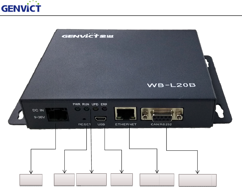
II. Equipment Installation
This section focuses on the installation of WB-L20B. First, we introduce how to install power
cord, antennas onto the corresponding interfaces. (To prevent damage to the equipment, please
make sure to connect the antennas before power on); Then, we introduce how to use PC connecting
to WB-L20B through Ethernet cable, and then configure WB-L20B and view log files.
P
o
o
we
r
Reset
WB-L20B Us
e
Figure 1
-
Indicator
e
r Guide
-
1 WB-L20F
r
USB
r
ont Panel
Ethe
r
r
net CAN/232
3
WB-L20B User Guide
4
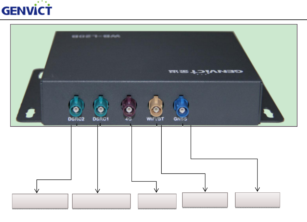
Figure 2-2 WB-L20B Rear Panel
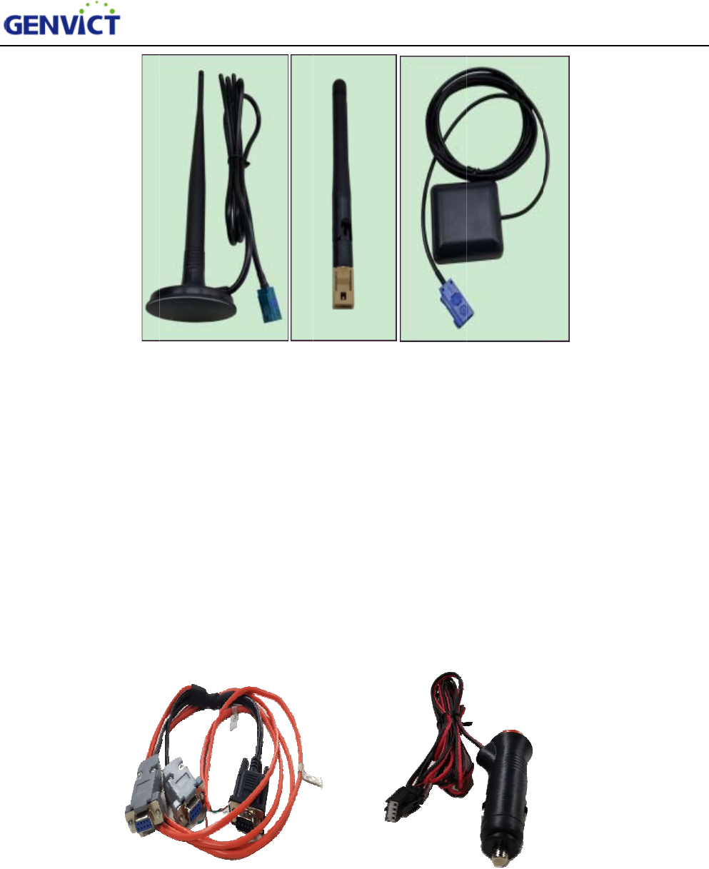
Figure 2-3 is the antenna picture of WB-L20B,orderly are DSRC antenna (two units), 4G antenna
(optional,this product is without 4G function), Wi-Fi/BT antenna, GNSS antenna. Before turning on
power, please install the antenna to the corresponding interface. DSRC antenna and GNSS antenna
should be installed outside the vehicle for better performance.
Wi-Fi/BT
DSRC Antenna 1
DSRC Antenna 2 4G GNSS
c
o
d
l
Figure
c
igar lighte
r
o
ther side a
r
d
ebugging)
l
evel). Pow
e
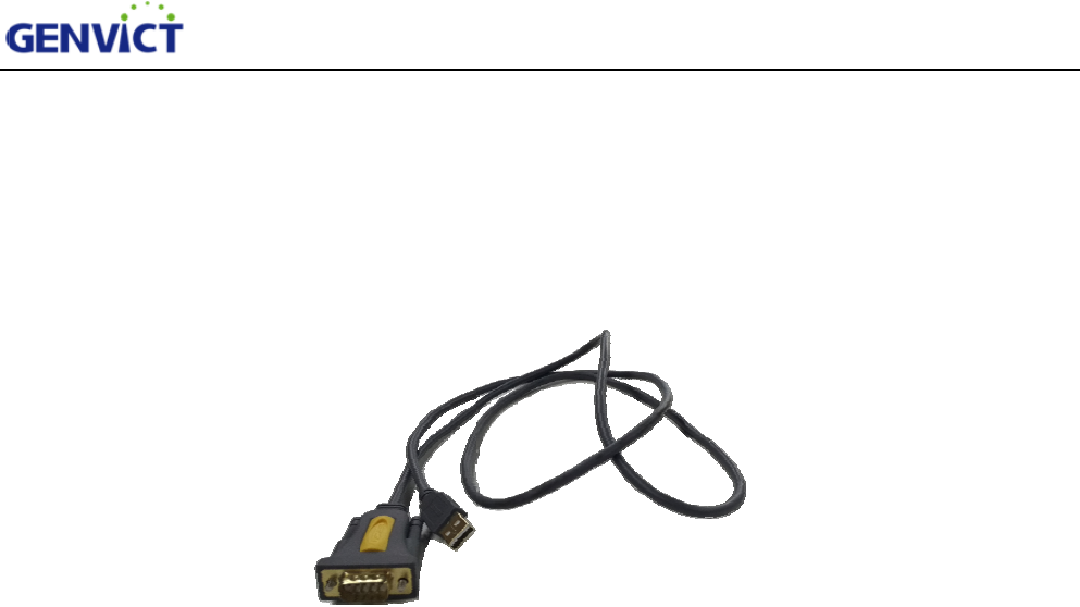
DB9 Sp
e
2-4 is the
p
r
power cor
d
r
e two DB
9
and two C
A
e
r cord can
e
cial Extensi
o
DSRC Ante
n
p
icture of a
c
d
9
female (D
B
A
N interfac
access to 9
v
o
n Wire
WB-L20B Us
e
n
na
Figure 2
-
c
cessories f
o
. For
D
B
9 female
I
es (brown
l
v
~ 36v D
C
Cig
a
Figure 2-
4
e
r Guide
Wi-Fi Ante
n
-
3 WB-L20B
o
r WB-L20
D
B9 specia
l
I
is standar
d
l
ine connec
t
C
input (it is
a
r Lighter Po
w
4
WB-L20B
A
n
na G
N
Antennas
B, orderly
a
l
extension
d
RS232, D
B
t
s to low le
v
recommen
w
er Cord
A
ccessories
N
SS Antenn
a
a
re DB9 sp
e
wire, one e
n
B
9 female
I
v
el, green l
i
ded to use
1
a
e
cial exten
s
nd is DB9
m
I
I is a seria
l
i
ne connect
s
1
2v DC inp
s
ion wire,
m
ale, on th
e
l
port for
s
to high
ut).
5
e
2
t
P
2
2
f
v
2
2
.1 Acce
s
WB-L
2
t
ransferring
P
C,one can
2
.2 Log-
i
2
.2.1 By
s
Take s
e
f
ollows:
1) Op
e
2) Ch
o
3) Co
n
4) Cli
c
v
ict
g
en to
c
2
.2.2 B
y
W
For se
t
Use X
s
1) Op
e
2) Sel
e
s
s toWB-
2
0B provid
e
data with
e
use this wi
r
i
n WB-L
2
s
erial po
r
e
rial port a
c
e
n Xshell5,
s
o
ose "SERI
A
n
figure para
m
c
k "Connec
t
c
omplete co
W
i-Fi
t
ting up Wi
-
s
hell5 to ac
c
e
n the Xshe
l
e
ct SSH as
p
L20B
e
s mini- B
U
e
xternal de
v
r
e connect
t
2
0B
r
t
c
cessing to
o
s
elect "ne
w
A
L" as prot
o
m
eters in S
E
t
", choose a
c
nnection.
-
Fi connect
i
c
ess device
l
l5, select "
n
p
rotocol, se
t
WB-L20B Us
e
U
SB male i
v
ices. Figur
e
t
o serial I o
f
Figure 2-
5
o
l Xshell5 f
o
w
" connecti
o
o
col incata
l
E
RIAL pa
n
c
cept and s
a
i
on, please
c
, the config
u
n
ew" conn
e
t
host addr
e
e
r Guide
nterface, it
e
2-5 is DB
9
f
DB9 spec
i
5
DB9 Seria
l
o
r example
,
o
n;
l
og;
n
el.
a
ve key. T
h
c
heck chap
t
u
ration ste
p
e
ction;
e
ss to 192.1
can be use
d
9
serial por
t
i
al extensio
n
l
Port Wire
,
the steps
o
h
en type in
u
t
er four, se
c
p
s are as fo
l
68.110.1, p
o
d
for install
i
t
wire. To a
n
wire (cab
o
f serial por
t
u
ser name:
r
c
tion two.
l
lows:
o
rt number
i
ng progra
m
a
ccess WB-
L
le is option
a
t
accessing
r
oot and p
a
uses the d
e
m
s and
L
20B by
a
l).
are as
a
ssword:
e
fault port
6
WB-L20B User Guide
7
number 22.
3) Click "OK", choose accept and save key. Then type in user name: root and password: victgen
to complete connection.
III. WB-L20B Automatic Start-up Items
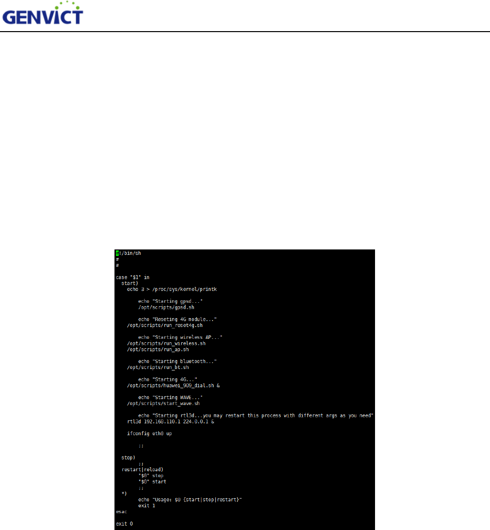
Check script /etc/init.d/S90init-stuff for WB-L20B startup items, here will explain how to
configure and edit each programwhich will run at the start of device.
1.To reviewscript S90init-stuff: vi/etc/init.d/S90init-stuff, as shown in figure 3-1:
Figure 3-1 Automatic Start Scripts
2. Script content is as follows:
gpsd.sh -- GPSD configuration script, through which user can configure GPSD serial port and
baud rate, the gpsdbaud rate is 115200.
run_wireless.sh -- Load Wi-Fi driver module, after running this script, device will act as an AP,
waiting wireless terminal to access by Wi-Fi.
run_ap.sh -- Hostapd configuration script, through whichuser can set IP address pool for client
devices.
run_bt.sh -- Bluetooth module loading script, after running this script,Bluetooth function is
WB-L20B User Guide
8
switch on.
start_wave.sh -- WAVE service module loading script, after running this script,DSRCfunction
is switch on.
rtl3d 192.168.110.1 224.0.0.1 -- Read local GNSS message, and send as multicast message
tomulticast group address 224.0.0.1 on Wi-Fi interface address 192.168.110.1.
IV. WB-L20B Software Use Guidance
4.1 Device Network Interface Introduction
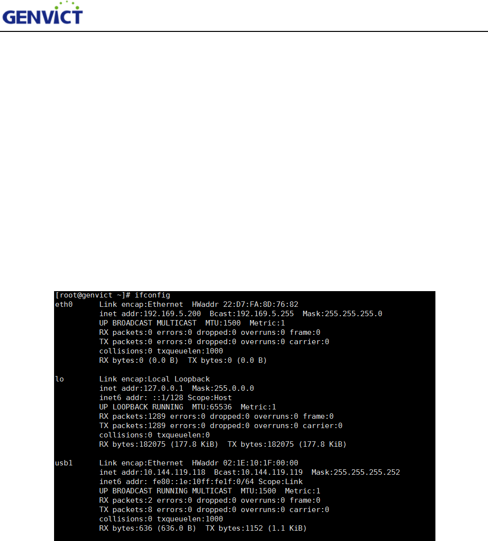
After login system, input command “ifconfig” to view device network interface information, as
shown in figure 4-1:
WB-L20B User Guide
9
Figure 4-1 Network Interface Info
Through “ifconfig”command, there are five network interfaces on the device, namely eth0, lo,
usb1, wave0 and wlan0. Eth0 is Ethernet interface, lo is local loopback interface, wave0 is DSRC
communication interface and wlan0 is Wi-Fi interface. Please note that SIM card is not plugged in, usb1
interface won't appear.
4.2Wi-Fi Use Guidance
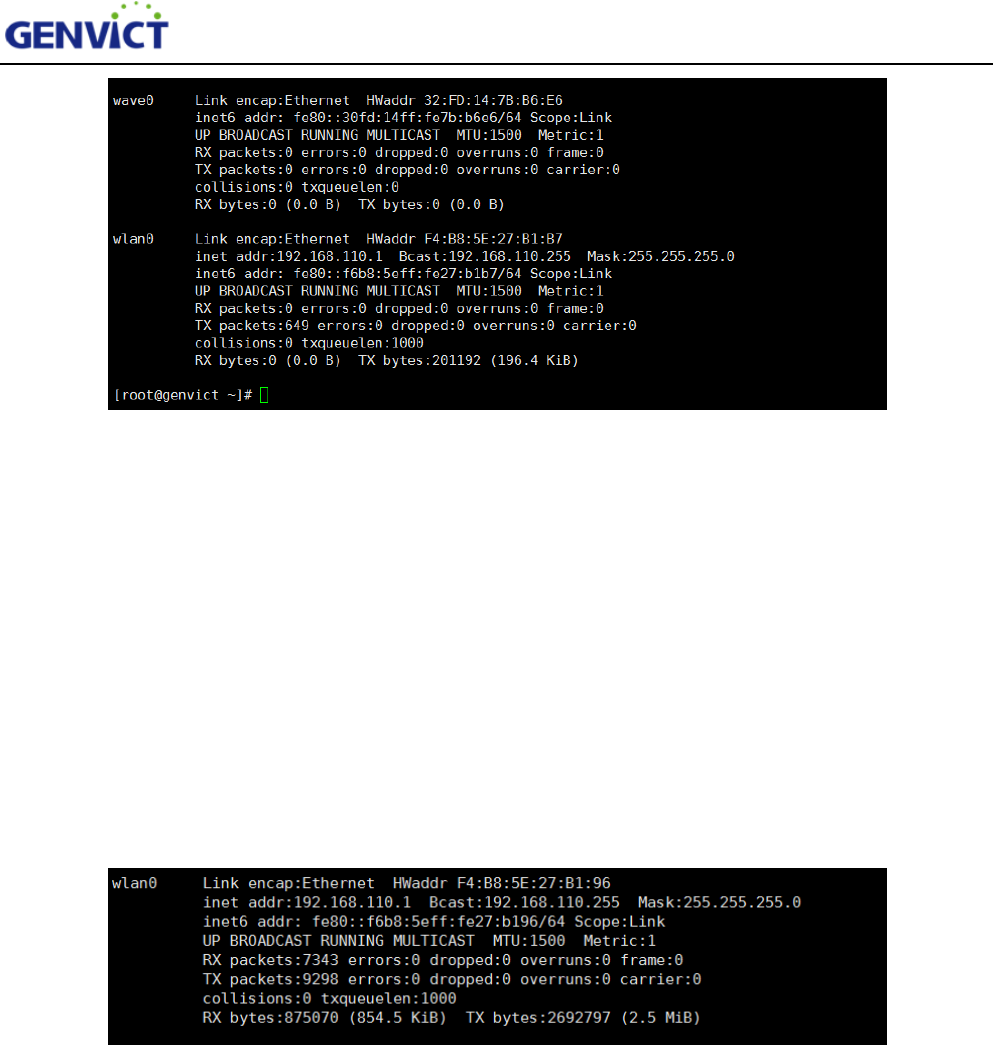
Type in command “ifconfig” to view device network interface information, as shown in figure 4-2:
Figure 4-2 Wi-Fi Interface
The default interface for Wi-Fi is wlan0and default IP address is 192.168.110.1, this is the AP
address forother devices to connect to. User can change this IP address by editing corresponding
configuration file. See the next section for detail.
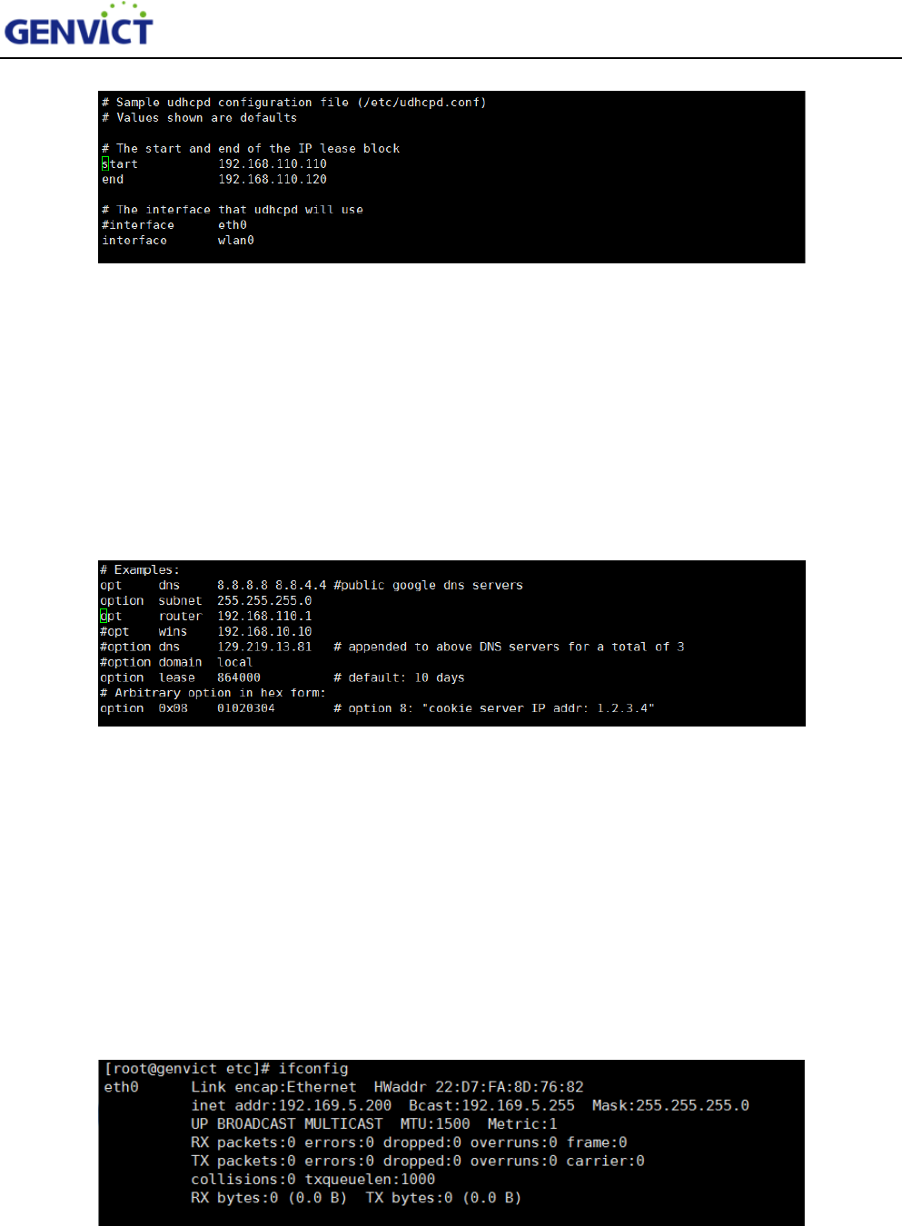
4.2.1 Modify Wi-Fi IP Address and Assign IP Address Pool
Use vi to open /etc/udhcpd.conf, find “start” and “end” items.
WB-L20B User Guide
10
Figure 4-2-1Wi-Fi Assign IP Address Pool
Change the start and end configuration in green spot to modify the address pool of AP.The default
IP addresses for client is in 192.168.110.0 segment, totally 10 addresses (From 192.168.110.110 to
192.168.110.120). Note that if you want to modify default address, please make sure that “opt router”
item in udhcpd.conf has the same address segment as AP address segment, shown in figure 4-2-2
highlighted in green.
Figure 4-2-2 Wi-Fi IP Address Detailed Info
4.3Ethernet Use Guidance
4.3.1 ManuallyConfigure Ethernet Interface IP Address
Connect WB-L20B to PC via Ethernet cable, log in and input“ifconfig eth0 up” and“ifconfig eth0
192.169.5.200 netmask 255.255.255.0”. Then eth0 IP address can be seen, as shown in figure 4-3. Note
thatWB-L20B and PC must configure in the same network segment.
Figure 4-3 ManuallyConfigure Ethernet Interface
WB-L20B User Guide
11
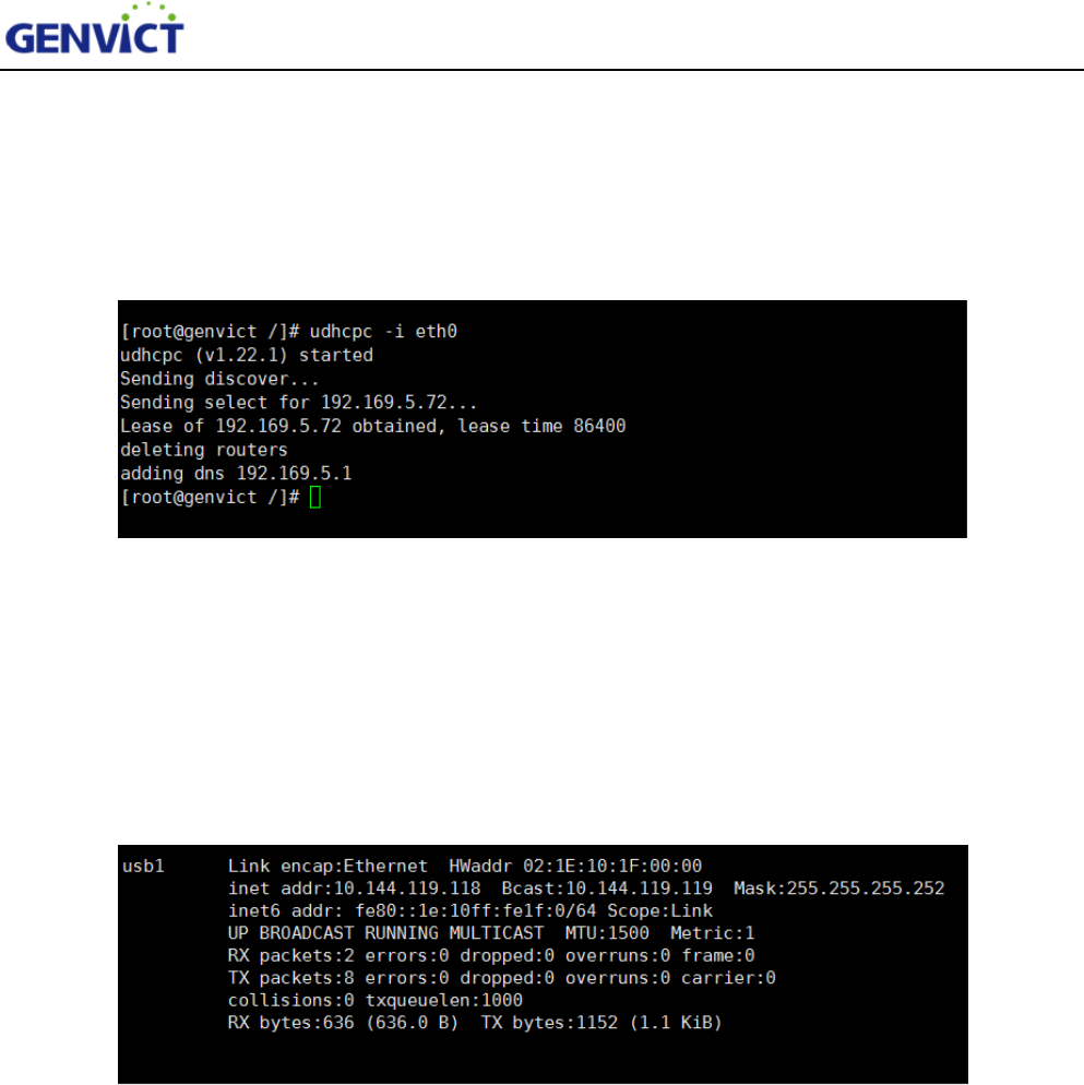
4.3.2 AutomaticallyAcquire Ethernet Interface IP Address
Connect WB-L20B to router via Ethernet cable, input “udhcpc -i eth0”, then WB-L20B’s Ethernet
interface can obtain IP address automatically, as shown in figure 4-3-1.
Figure 4-3-1 AutomaticallyAcquire IP Address
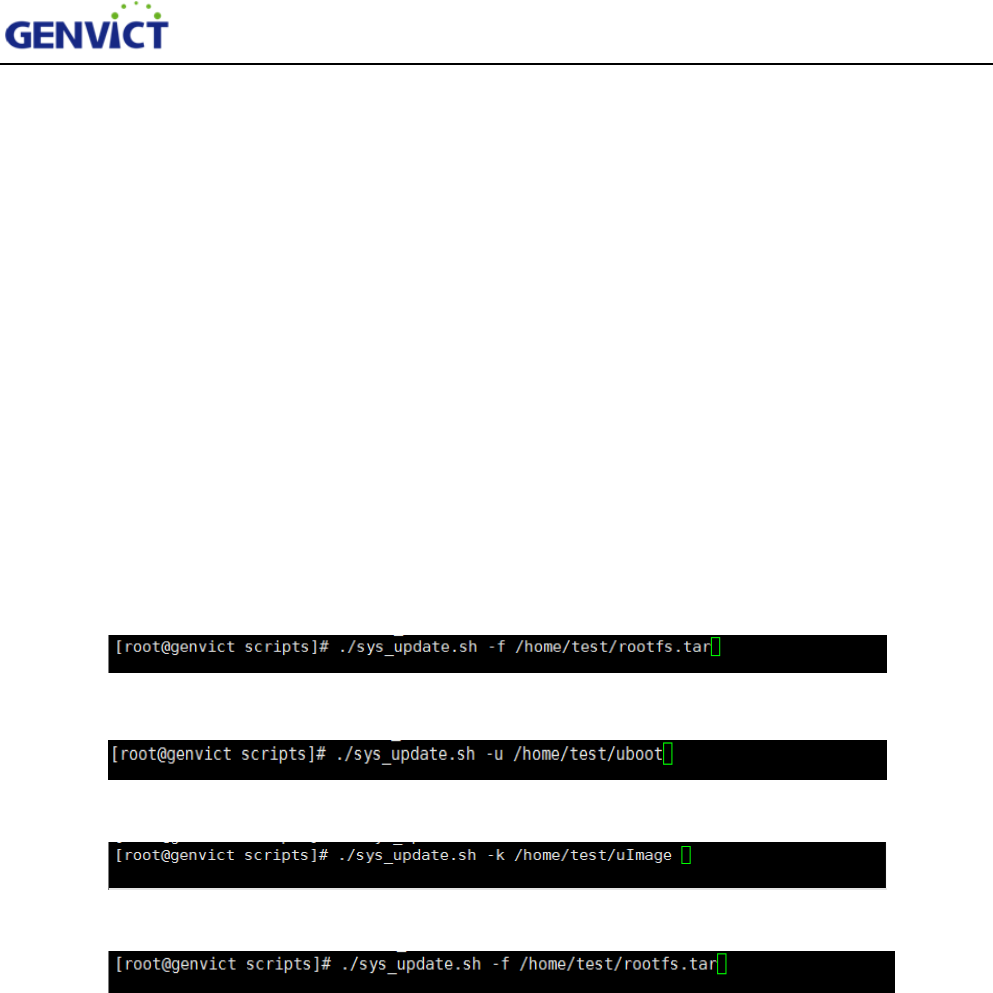
4.4 4G Network Interface Use Guidance
Usb1 is the 4G network interface.WB-L20B obtained IP address 10.144.119.118from server. The
existence of this address stands that the device is capable of accessing to Internet, as shown in figure
4-4.
Figure 4-4 4G Network Interface
4.5 System Upgrading Introduction
4.5.1 Upgrading File Preparation
First of all, prepare the upgrade file such as kernel;copy upgrading file to any path of the device. To
do this, user can use Linux SCP command under Linux or SSH, WinSCPunder Windows. Now
takingWinSCP as an example, the access configuration steps are as follows:
1) Open the WinSCP, configuration interface will appear as shown in figure 4-5;
2) SelectSCP as protocol, use 192.168.2.100 as host name, default 22 as port number, “root” as
WB-L20B User Guide
12
user name and “victgen” as password.Click "login" to complete access. (If host key related security
warning appears, select "update".)
After accessing using WinSCP shown in Figure4-5-1, with PC’s file directory on the left and
WB-L20B file directory on the right.Then user can do file operations. As user has root privilege, please
be cautious when applying operations.
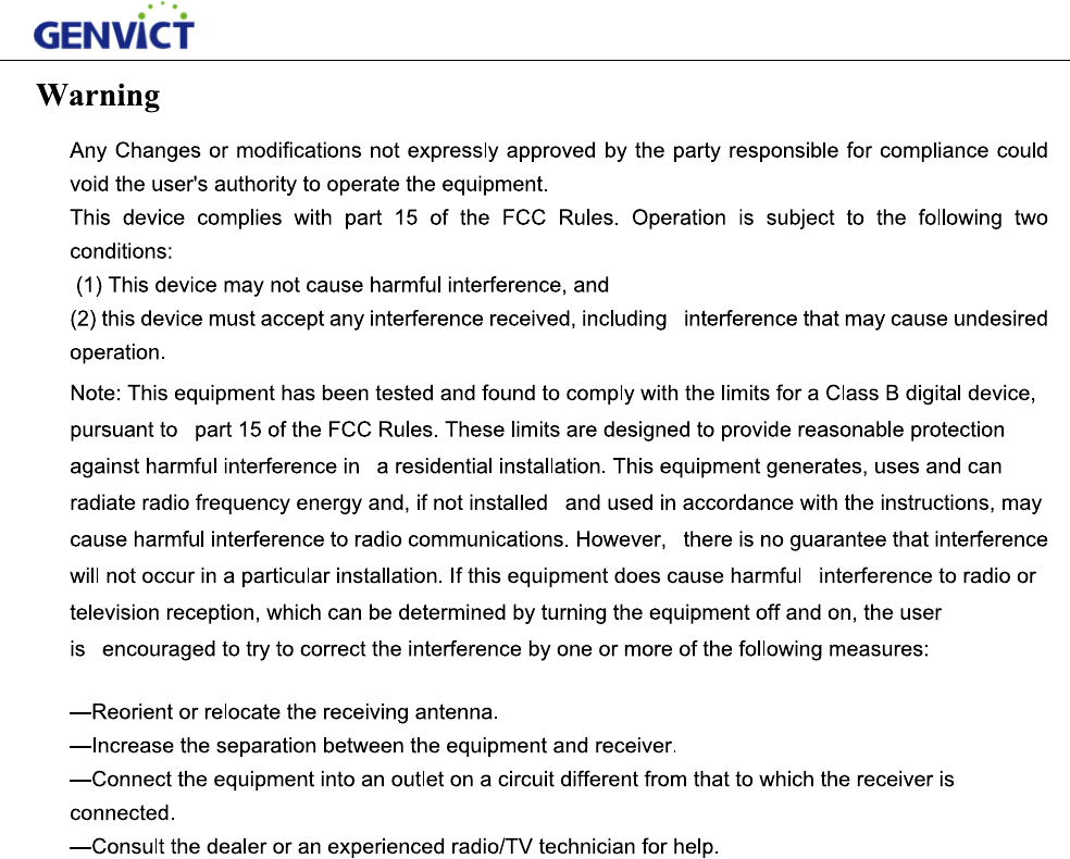
4.5.2 Parameter Introduction
Viewsys_update.sh under /opt/scripts directory, this script supports four kinds of upgrading,
including DTB, Uboot, Kernel and FS. User can use command line to upgrade. (For
example,./sys_update.sh -x /xxx/xxxxxx.xxx)
1) -x to distinguish four types of upgrading files:
-d stands for DTB upgrading
-u stands for Uboot upgrading
-k stands for Linux Kernel upgrading
-f stands for Filesystem upgrading
-d、-u、-k、-f can be used in any combination, this means that not only one type upgrading file,
but multiple combination files can be used for upgrading. For example,-u, -k, -d, and -f using
at the same time means the device needs to upgrade using DTB, Uboot, Kernel and FS files at
the same time. Note that parameters are all lowercase letters.
2) /xxx/xxxmeans that upgrade file can locate in any path.
3) xxx.xxxstands for upgrading file name, this name can be user defined and has no format
requirements

WB-L20B User Guide
13
Technical Specification
Mechanical Properties
Size 175*145*30(mm)
Shell Material Sheet Metal Parts
Weight About 700g
Color Black
Installation Pre-install
Electric Properties
Power Supply Mode DC9V-36V
Communication Distance 800M
Radio Frequency Output
Power
-0.4dBm(Do not include the antenna gain and
regulation)
RF Performance
Working Frequency: 5.855GHz-5.925GHz
Channel Bandwidth: 10M (172~184),20M
Wireless Transmission Rate: 3M, 4.5M, 6M, 9M, 12M,
18M, 24M, 27Mbps
Channel Switching Delay<4ms
Environment Properties
Operating Temperature -30℃~+50℃
Storage Temperature -45℃~+85℃
Operating Humidity 10%-95% no condensation
FCC Radiation Exposure Statement:
This equipment complies with FCC radiation exposure limits set forth for an uncontrolled environment .
This transmitter must not be co-located or operating in conjunction with any other antenna or
transmitter.
This equipment should be installed and operated with minimum distance 20cm between the radiator&
your body.
14

S
S
GEN
V
Add: 1
S
henzhen,
G
Tel: (0
GEN
V
Add:
U
S
treet, Hig
h
Tel: (0
The u
n
Appli
c
Hard
w
V
ICT Hea
d
2/F Tower
G
uangdong
,
086) 0755-
2
V
ICT Depa
U
nit 903, B
u
h
-tech Zone
086)028-8
3
n
derlying
s
c
ation soft
w
w
are techn
i
d
quarters (
S
A, R&D B
u
,
P.R.C. 51
8
2
6030288
rtment of
R
u
ilding A,
C
, Chengdu,
3
168577 Fa
x
s
oftware te
c
w
are techn
i
i
cal suppo
r
WB-L20B Us
e
S
henzhen)
u
ilding, Tsi
n
8
057
Fax: (00
8
R
esearch
P
C
hanghong
Sichuan, P
.
x
:(0086)02
8
c
hnical su
p
i
cal suppo
r
r
t: shild@g
e
r Guide
n
ghua Hi-
T
8
6)0755-33
6
P
rogram
Science an
d
.
R.C. 6100
4
8
-8316857
8
p
port:wa
n
r
t:xuzq
@g
envict.co
m
T
ech Park,
K
6
31693
d
Technolo
g
4
1
8
ng
lx@gen
v
g
envict.co
m
m
K
eyuan Ro
a
g
y Mansio
n
v
ict.com
m
a
d, Nansha
n
n
, No 199 T
i
n
District,
i
anfu Fourt
h
15
h