Go Networks WLS-2100F-000 Outdoor Phased-Array WLAN AP User Manual GO MBW Getting Started Guide
Go Networks Inc. Outdoor Phased-Array WLAN AP GO MBW Getting Started Guide
User manual

GO Metro Broadband Wireless
GO Metro Broadband Wireless GO Metro Broadband Wireless
GO Metro Broadband Wireless
Getting Started
Getting Started Getting Started
Getting Started
Guide
GuideGuide
Guide

GO MBW Getting Started Guide
GO MBW Getting Started GuideGO MBW Getting Started Guide
GO MBW Getting Started Guide
Trademarks and Licensing Agreement
© 2006 GO Networks, Inc. All rights reserved.
All information contained in this document is protected by international copyright
treaties. No information may be copied or reproduced without the express written
consent of GO Networks Inc.
GO Metro Broadband Wireless, Go MBW, WLAN Sector Base Station, WLS, GO
Wireless Network Controller, and WNC are all trademarks of GO Networks Inc.
Any duplication, transmission by any method, or storage in an information retrieval
system of any part of this publication for other purposes other than those stated
above is strictly prohibited without the specific written permission of GO Networks,
Inc. This includes, but is not limited to, transcription into any form of computer
system for audio, text, print, or visual retrieval. All rights under federal copyright
laws and international laws will be strictly enforced.
All other trademarks and registered trademarks are the property of their respective
owners.
GO Networks Inc.
1943 Landings Drive • Mountain View, CA 94043 • USA
Tel +1.650.962.2000 • Fax +1.650.962.2010
Email support@gonetworks.com
Version 1.03

GO MBW Getting Started Guide
GO MBW Getting Started GuideGO MBW Getting Started Guide
GO MBW Getting Started Guide
Draft Version - Confidential - Page 1
The following information is for FCC compliance:
This device complies with part 15 of the FCC Rules. Operation is subject to the following
conditions:
(1) this device may not cause harmful interference, and
(2) this device must accept any interference received, including interference that may
cause undesired operation.
This equipment has been tested and found to comply with the limits of a Class B digital
device, pursuant to Part 15 of the FCC Rules. These limits are designed to provide
reasonable protection against harmful interference when the equipment is operated in a
residential environment, this equipment generates, uses, and radiates radio frequency
energy, and if not installed and used in accordance with the instructions, may cause harmful
interference. However there is no guarantee that interference will not occur.
To meet regulatory restrictions, the outdoor access point must be professionally installed.
The Part 15 radio device operates on a non-interference basis with other devices operating
at this frequency when using its internal antennas. Any changes or modifications not
expressly approved by Go Networks could void the user's authority to operate the
equipment.
The (internal) antennas used for this transmitter must not be co-located or operating in
conjunction with any other antenna or transmitter.

GO MBW Getting Started Guide
GO MBW Getting Started GuideGO MBW Getting Started Guide
GO MBW Getting Started Guide
Draft Version - Confidential - Page 2
Table of Contents
Introduction...........................................................................................................................................................4
GO Wireless Network Controller (WNC)...............................................................................................................5
Deployment Options.........................................................................................................................................5
In-line Traffic Configuration..........................................................................................................................6
Non In-line Traffic Configuration ..................................................................................................................7
WNC Safety Information...................................................................................................................................9
Electrical Safety ...........................................................................................................................................9
Electro-Static Discharge Precautions (ESD)................................................................................................9
Redundant Power Supply ............................................................................................................................9
Electricity Supply........................................................................................................................................10
WNC Installation Instructions .........................................................................................................................11
Cable Connections.....................................................................................................................................11
GO WLAN Sector Base Station (WLS)...............................................................................................................13
WLS Package Components ...........................................................................................................................13
Deployment Options.......................................................................................................................................13
WLS Safety Information .................................................................................................................................14
WLS Lightning Protector ............................................................................................................................14
WLS Component and Cable Connections......................................................................................................16
Ethernet Connection ..................................................................................................................................17
Power Connection......................................................................................................................................18
Installation Process ........................................................................................................................................19
Site Survey ................................................................................................................................................19
Infrastructure Development........................................................................................................................19
Hardware and Connectors Installation .......................................................................................................20
Power Up and Software Configuration.......................................................................................................25
Post Installation Testing Procedure ...........................................................................................................26
Configuring the WNC..........................................................................................................................................27
Connect and Access the Wireless Network Controller (WNC) ...................................................................27
Step1: Configure the Access Interface.......................................................................................................27
Step 2: Configure the Net Interface............................................................................................................27
Step 3: Configure the Default Gateway......................................................................................................27
Step 4: Configure the DHCP Server ..........................................................................................................28
Step 5: Configure the DNS.........................................................................................................................28
Step 6: Configure the Radius Authentication Client Connectivity...............................................................28
Step 7: Configure the Radius Authentication Shared Key..........................................................................28
Step 8: Configure the Radius Authentication Port Connectivity .................................................................28
Step 9: Configure the Radius Authentication Source IP Address...............................................................28
Step 10: Configure the Radius Accounting Client Connectivity..................................................................28
Step 11: Configure the Radius Accounting Shared Key.............................................................................29

GO MBW Getting Started Guide
GO MBW Getting Started GuideGO MBW Getting Started Guide
GO MBW Getting Started Guide
Draft Version - Confidential - Page 3
Step 12: Configure the Radius Accounting Port Connectivity ....................................................................29
Step 13: Configure the Radius Accounting Source IP Address..................................................................29
Step 14: Update Radius Settings...............................................................................................................29
Step 15: Save the Configuration ................................................................................................................29
Configuring the WLS...........................................................................................................................................31
Connect and Access the WLAN Sector Base Station ................................................................................31
Step 1: Configure the Fast Ethernet Interface............................................................................................32
Step 2: Configure the Default Gateway......................................................................................................33
Step 3: Configure the Dot11Radio interface...............................................................................................33
Step 4: Configure the ESSID .....................................................................................................................33
Step 5: Set Radio Data Rates....................................................................................................................33
Optional Step: Set WEP Privacy Mode ......................................................................................................33
Step 6: Enable the Radio Interface ............................................................................................................33
Step 7: Save the Configuration ..................................................................................................................33
WLS Configuration Example ..........................................................................................................................34
Troubleshooting..................................................................................................................................................37

GO MBW Getting Started Guide
GO MBW Getting Started GuideGO MBW Getting Started Guide
GO MBW Getting Started Guide
Draft Version - Confidential - Page 4
Introduction
GO Networks’ Metro Broadband Wireless (MBW) Solution. The MBW is the industry's
first broadband wireless access (BWA) system engineered from the ground up to
address the fundamental challenges of metro scale 802.11 access.
The MBW was designed to enable service providers to offer software and hardware
redundancy in large-scale, high-interference environments while providing a WiFi and
802.11 standards compliant solution using standard end-user equipment.
The GO broadband wireless access solution integrates smoothly and transparently
between client-based devices such as laptops, handsets, PDAs, CPEs, etc. and the
transport layer which sends data to the Internet and beyond. At the same time,
session-specific information is relayed to the RADIUS server to enable billing,
reporting, and statistics.
GO-MBW can be deployed in one of two ways:
• Full solution including both access points, known as WLAN Sector Base Stations
(WLS) and one or more network controllers, known as Wireless Network
Controllers (WNC).
• Standalone access points featuring the WLAN Sector Base Stations operating with
third party network controllers.
The GO Metro Broadband Wireless solution’s Getting Started Guide documents both
of these deployments, and also offers information and instructions for quickly
installing and configuring both the WLS and the WNC units. The Getting Started
Guide also includes a troubleshooting section, offering detailed instructions on a
variety of communication, authentication or connection problems that might occur.
GO MBW Getting Started Guide
GO MBW Getting Started GuideGO MBW Getting Started Guide
GO MBW Getting Started Guide
Draft Version - Confidential - Page 5
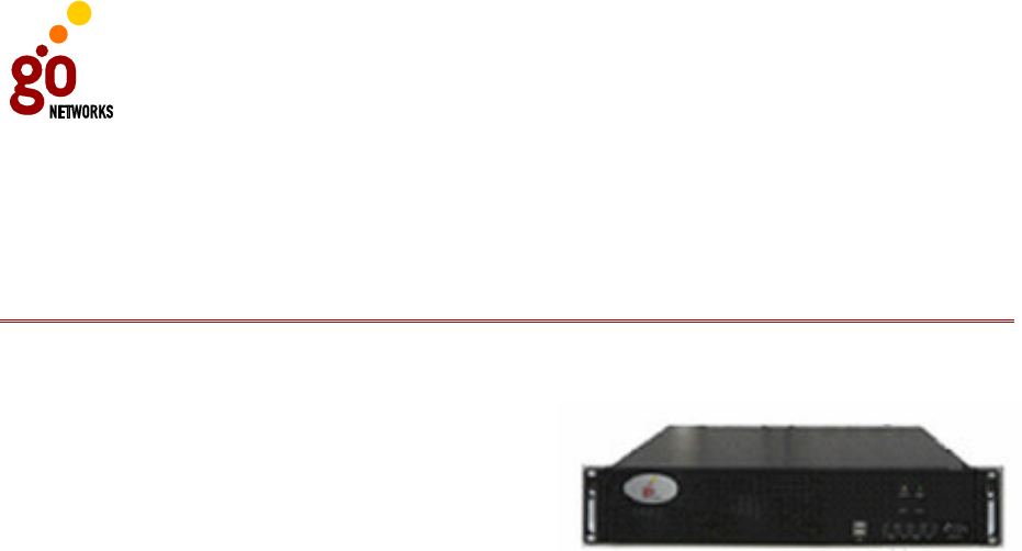
GO Wireless Network Controller (WNC)
The Wireless Network Controller (WNC) is a high-performance server/controller that
provides functionality such as:
• Inter-base station optimization
• Fast roaming between base stations
• Access to controller functionality,
including user authentication
• Quality-of-Service (QoS) provisioning
per user or user profile
• Centralized interface for management and billing systems.
The Wireless Network Controller connects between the operator backbone/Internet
traffic and signaling and the WLAN access (typically a WLAN Sector Base Station). All
traffic passes through the Wireless Network Controller either on its way to the
Internet or from the Internet to the station (via the local WLAN Sector Base Station)
Wireless Network Controller offers global spectrum management and is carries
central responsibility for dynamically managing the network for optimal system
performance. In addition, the Wireless Network Controller is responsible for
determining whether a station should “roam” to another WLAN Sector Base Station in
the system.
Deployment Options
The Wireless Network Controller can be deployed in one of the following ways:
• In-line Traffic: Provides global spectrum management and load balancing of
stations between WLAN Sector Base Stations and between channels within the
WLAN Sector Base Stations. All Internet-bound traffic is routed through the WNC.
• Non In-line Traffic: Global Spectrum management and users’ load balancing
between WLAN Sector Base Stations/Channels.
The deployment process involves first indoor components of the system, followed by
the outdoor installation of the WLS unit on a pole or rooftop wall. Installation and
configuration of both the WNC and the WLS are detailed in the following sections.
GO MBW Getting Started Guide
GO MBW Getting Started GuideGO MBW Getting Started Guide
GO MBW Getting Started Guide
Draft Version - Confidential - Page 6
In-line Traffic Configuration
PDA
Desktop PC \
Notebook PC
Pocket-PC
MBW-WLS-3100
WLS Power SupplyWLS Power Supply
Lightning Protector
MBW-WNC-AC2-5020 \
DC-5010
Radius ServerRadius Server
Router \ Switch
Router \ Switch
230 \ 110
PDA
Desktop PC \
Notebook PC
Pocket-PC
MBW-WLS-3100
WLS Power SupplyWLS Power Supply
Lightning Protector

GO MBW Getting Started Guide
GO MBW Getting Started GuideGO MBW Getting Started Guide
GO MBW Getting Started Guide
Draft Version - Confidential - Page 7
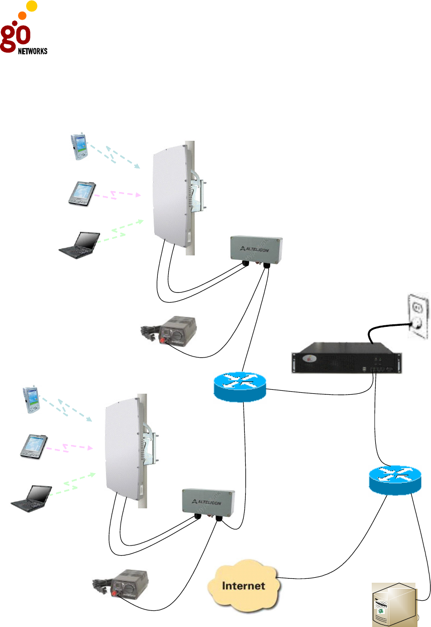
In the in-line traffic configuration, all traffic is routed through the WNC, enabling
both global and local spectrum management and accounting services through the
Radius server.
To deploy the system in this configuration:
1. Connect all indoor components. These include
Lightning protector
WLS power supply
WNC unit
2. Install the WLS unit.
3. After mounting the WLS unit (see the section on Installing the WLS), verify
that client stations have connectivity to the Internet via the WLS unit.
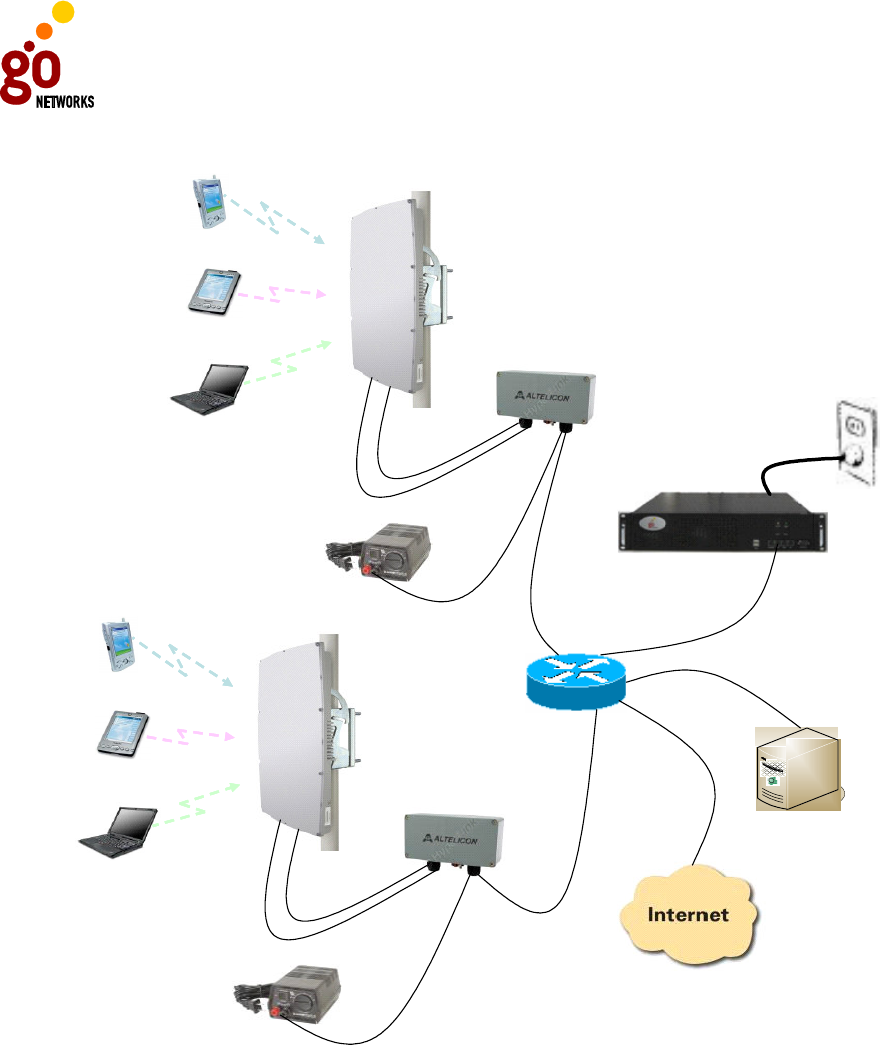
Non In-line Traffic Configuration
In the non in-line traffic configuration, all traffic is routed directly to the
router/switch. The WNC can be added to the configuration to provide global
spectrum management.
To deploy the system in this configuration:
1. Connect all indoor components. These include:
Lightning protector
WLS power supply
2. Install the WLS unit.
3. After mounting the WLS unit (see the section on Installing the WLS), verify
that client stations have connectivity to the Internet via the WLS unit.
GO MBW Getting Started Guide
GO MBW Getting Started GuideGO MBW Getting Started Guide
GO MBW Getting Started Guide
Draft Version - Confidential - Page 8
Radius ServerRadius Server
Router \ SwitchRouter \ Switch
MBW-WNC-AC2-5020 \
DC-5010
230 \ 110
PDA
Desktop PC \
Notebook PC
Pocket-PC
MBW-WLS-3100
WLS Power SupplyWLS Power Supply
Lightning Protector
PDA
Desktop PC \
Notebook PC
Pocket-PC
MBW-WLS-3100
WLS Power SupplyWLS Power Supply
Lightning Protector
GO MBW Getting Started Guide
GO MBW Getting Started GuideGO MBW Getting Started Guide
GO MBW Getting Started Guide
Draft Version - Confidential - Page 9
WNC Safety Information
Be careful when attempting to lift the equipment. This equipment is designed for
installation in a suitable environment with free airflow. Do not block any air vents in
the rear panel or on the sides. There are no air vents on the top or bottom of the
unit. However, liquids of any type (water, coffee, etc.) should not be placed on or
near the unit.
Electrical Safety
It is highly recommended that this equipment be connected to a suitable,
uninterruptible power supply unit (UPS).
Before connecting main leads to the units, check that the power cords(s), plug(s)
and distribution sockets are in good condition.
Take all necessary precautions when working with disassembled units while they are
still under power.
Electro-Static Discharge Precautions (ESD)
Take all necessary precautions when handling printed circuit boards, as all parts in
the server are prone to ESD damage.
Use wrist straps that are suitably earthed when removing any parts from the
systems.
Redundant Power Supply
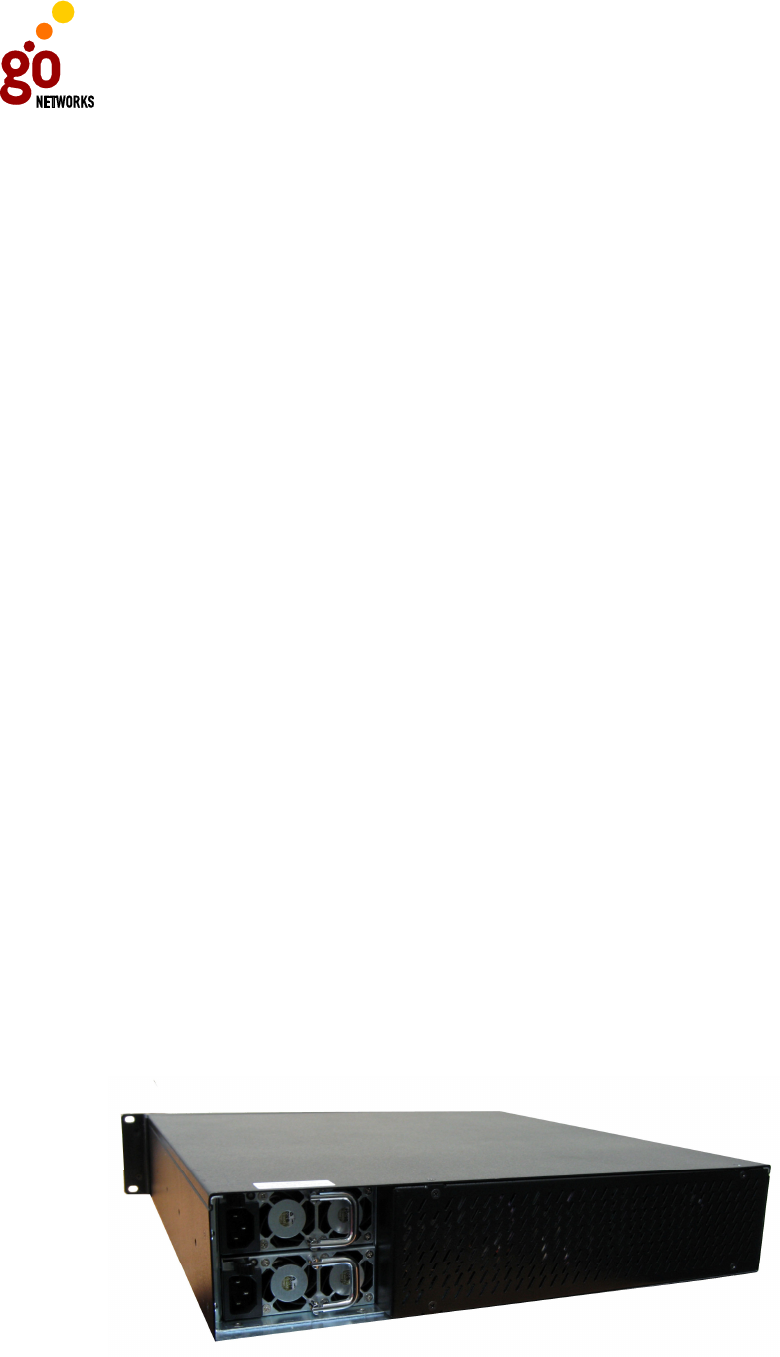
WNC units that run on AC power have the option of using a redundant power supply.
This option is only available for AC.
CAUTION. When installing the unit, remember that there is a risk of electric
shock.
If you only disconnect one power cord, the danger of hazardous voltage from the
unit remains a possibility. Disconnect both power cords to remove the risk of
hazardous voltage from the unit.

GO MBW Getting Started Guide
GO MBW Getting Started GuideGO MBW Getting Started Guide
GO MBW Getting Started Guide
Draft Version - Confidential - Page 10
When both power supplies are installed (in AC only), it is recommended that you
plug in both power supplies. When only one power supply is connected, the unit will
beep continuously to indicate the absence of power in the second connection. This
indicates either a faulty AC module, or the fact that one power supply has not been
connected. To stop the warning beep, either connect the second power supply, thus
creating a redundant power source, or disconnect the second power supply unit
completely from the WNC unit.
Electricity Supply
AC Power Operated Unit
Before connecting the WNC unit to the electricity supply, review the information
given on the apparatus rating plate and verify that:
• Your power supply is single phase A.C. (alternating current) of the stated
frequency with neutral nominally at earth potential.
• Your supply voltage is 100-240 VAC or 115-240 VAC (refer to rating label).
• The current rating is within the capacity of your UPS outlet.
• Your plug or electricity supply circuit is fitted with a suitable branch circuit which
is rated 125% of the unit rating or of the selected power cord.
• You should use molded cables when installing the WNC.
DC Power Operated Unit
• The WNC unit should be used in areas designated as “RESTRICTED ACCESS
LOCATIONS” with limited traffic.
• Power supply cables should be 2 sets of 2x18 AWG copper wire: using UL Listed
cable only.
• Use a UL-approved x A circuit breaker as disconnect device incorporated in the
fixed Wiring (between centralized DC power system and power entry module).
• Verify that “ON” and “OFF” positions of the circuit breaker are clearly marked and
that the circuit breaker is accessible.
• This equipment should be connected directly to the DC supply system grounding
electrode conductor, to a bonding jumper from a grounded terminal bar, or to a
bus to which the DC supply system-grounding electrode is connected.

GO MBW Getting Started Guide
GO MBW Getting Started GuideGO MBW Getting Started Guide
GO MBW Getting Started Guide
Draft Version - Confidential - Page 11
WNC Installation Instructions
• The unit should be mounted in a standard 19-inch equipment rack positioned on
a shelf.
• The two L brackets that are part of the unit should be connected to the 19-inch
rack with screws.
• The intake and exhaust ports for cooling air are located on the front and rear and
both sides of the chassis. Since there are no cooling ports on the top or bottom of
the unit, multiple units can be stacked with little clearance requirements within a
rack.
Cable Connections
In addition to the power supply connections, the WNC also features a control panel
on the front which enables you to connect the Access interface, Net interface, and a
Management interface (used during the initial configuration).
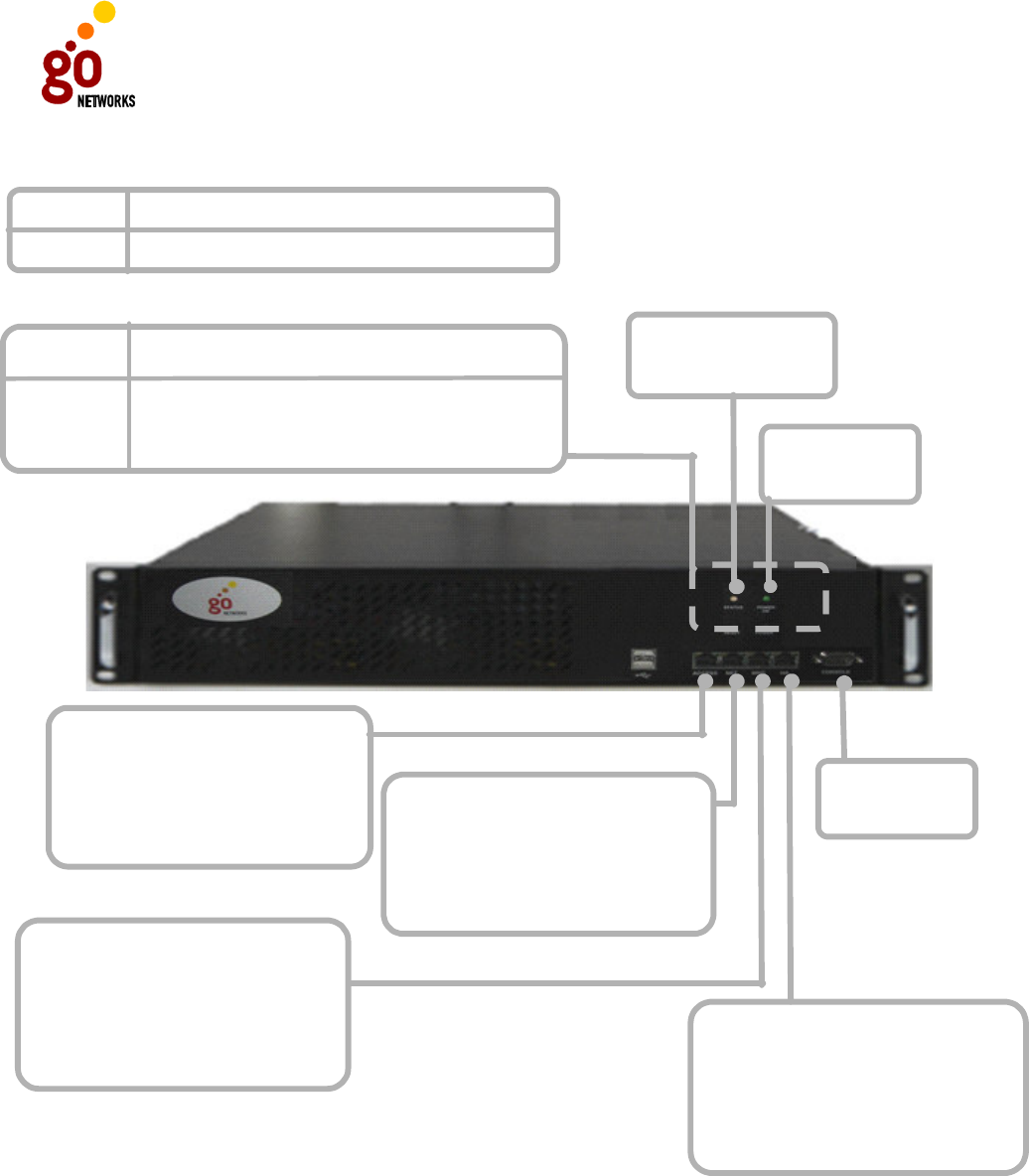
The MAC address on the sticker of the unit indicates the Access port. The High
Availability interface is not supported in Release 1 of the WNC. In addition, there are
two LEDs to indicate the Connection Status and Power Status of the unit.
If the Status light is red, the following procedure should be followed:
1. Check the physical connections to the unit to make sure all cables are
securely and firmly connected.
2. Shut the unit down and restart. Wait 5 second before restarting.
3. Call technical support.
GO MBW Getting Started Guide
GO MBW Getting Started GuideGO MBW Getting Started Guide
GO MBW Getting Started Guide
Draft Version - Confidential - Page 12
Power:
Solid green
Status:
Green - Operational
Red - Problem
Access Interface:
Blinking orange and green light
indicates activity (data transfer
rates of up 1Gbps).
The Access Interface connect to
the Access Points.
Net Interface:
Blinking orange and green light
indicates activity (data transfer
rates of up 1Gbps).
The Net Interface connects to the
Internet/Intranet.
Management (MNG) Interface:
Blinking orange and green light
indicates activity (data transfer
rates of up 1Gbps).
The MNG Interface is for secure
management.
High Availability (HA) Interface:
Blinking orange and green light
indicates activity (data transfer
rates of up 1Gbps).
The HA Interface is for backing up
the Access Controller.
Consol Port:
RS232
LED Indicators
Unlit There is no power connection.
Blinking Green
Power On
Green Unit is operational.
Red A built-in test has failed.
Green Unit is on.
Unit is powering up.
Status
Micro
-
Switches
Press to turn unit on.Power
Press to reset unit.
Reset

GO MBW Getting Started Guide
GO MBW Getting Started GuideGO MBW Getting Started Guide
GO MBW Getting Started Guide
Draft Version - Confidential - Page 13
GO WLAN Sector Base Station (WLS)
The WLAN Sector Base Station (WLS) is a high-performance WLAN base station that
supports the simultaneous use of two non-overlapping 802.11b/g channels within a
120° sector. The WLAN Sector Base Station provides a wireless access point through
which WiFi mobile devices can connect to the Internet for voice, video, and data
communication.
WLS Package Components
The WLS unit is shipped ready to install. The WLS unit is packaged with two
connectors: an RJ45 connector with a water-proof cover and a power connector with
a water-proof cover.
In addition, it is recommended that you also order a mounting kit (either wall mount
or pole mount version). The contents of each kit, which is ordered separately, is
detailed in the Installation Process section.
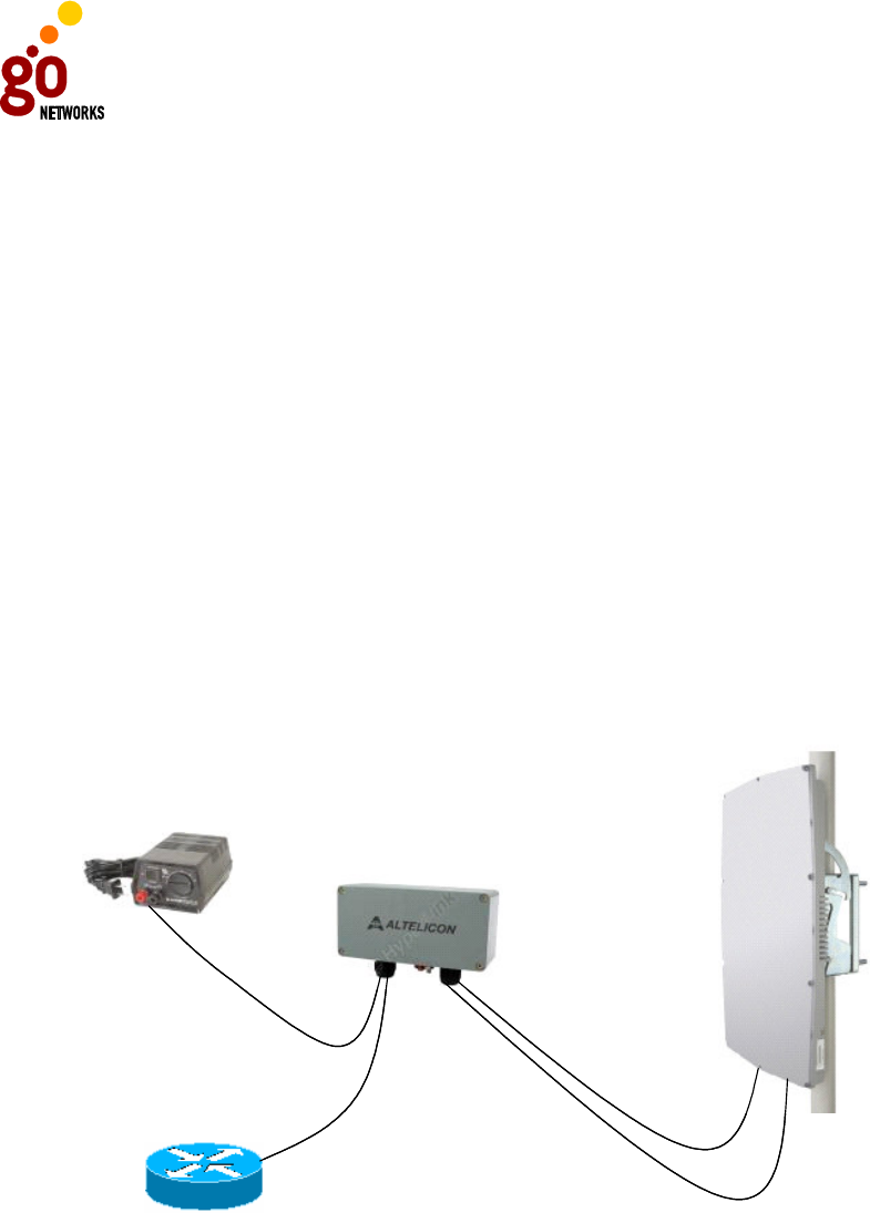
Finally, a typical deployment would include installation of a lightning protector, such
as the optional one that GO Network can supply.
Because cable requirements are often unique to the location and deployment
topology of each installation, power and Ethernet cables are not included in the
installation kit. For more info on cable requirements and connections, see WLS
Component and Cable Connections.
Deployment Options
The WLAN Sector Base Station can operate in one of two modes:
• Comprehensive Mode (MBW-WLS-3100): the WLAN Sector Base Station can
be configured to communicate with the GO Wireless Network Controller (WNC). It
will continue to provide local spectrum management and load balancing
capabilities, but will also be managed by the Wireless Network Controller, which
will provide a more comprehensive global network spectrum management and
load balance capabilities across additional WLAN Sector Base Stations to optimize
performance for all stations.
• Standalone (MBW-WLS-3200): the WLAN Sector Base Station can be
configured to communicate with 3rd party standard Access Controllers. In this
configuration, it will provide local spectrum management and load balancing
capabilities.
GO MBW Getting Started Guide
GO MBW Getting Started GuideGO MBW Getting Started Guide
GO MBW Getting Started Guide
Draft Version - Confidential - Page 14
The WLAN Sector Base Station can be mounted on either a pole or a wall to provide
maximum exposure and is designed to operate either indoors or outdoors without
any degradation of service.
WLS Safety Information
RF Exposure
This outdoor access point product has been found to be compliant to the
requirements set forth in CFR 47 section 1.1307 addressing RF Exposure from radio
frequency devices as defined in OET Bulletin 65. The outdoor access point should be
positioned more than 8 inches (20 cm) from your body or nearby person.
WLS Lightning Protector
When the WLS unit is installed in an outdoor location, all indoor components
(Ethernet, power supply) should be connected through a lightning protector.
WLS Power Supply
MBW-WLS-3100
Router \ Switch
Lightning Protector
WLS Power Supply
MBW-WLS-3100
Router \ Switch
Lightning Protector
The purpose of the lightning protection is to protect people and equipment located
indoors from lightning that might strike the WLS or its outdoor cables. Therefore,
the lightning protector (3001) device should be installed indoors, as close as possible
to the point where the cables enter the building. The lightning protector can also be
installed outdoor, as long as the cables that go from it indoors are well protected
from lightning between the box and the building entrance.

GO MBW Getting Started Guide
GO MBW Getting Started GuideGO MBW Getting Started Guide
GO MBW Getting Started Guide
Draft Version - Confidential - Page 15
Note: If the WLS is connected To a high current DC power line, a 4A
slow blow fuse, suitable for up to 100VDC should be placed on
the negative (-) wire.
Noter: Si le WLS est connecte a une puissante alimentation CC, un
fusible 4A Slow Blow pouvant soutenir jusqu’au 100VDC doit
être place sur le câble négative (-).
The WLS unit is connected to the WLS power supply via the lightning protector. It is
highly recommended that you place the WLS power supply in an indoor location.
Alternatively, if the WLS unit is not connected to the power supply, but to a fixed DC
line (for example, in a cellular base station) that is effectively not limited in current,
a circuit breaker must be placed between the DC source and the lightning protector.
The circuit breaker is rated at 4 ampere, and is reliable for up to 100 VDC.
The WLS unit is also connected, again through the lightning protector, to the WNC
unit, which offers connectivity to the Internet as well as global and local spectrum
management.
GO MBW Getting Started Guide
GO MBW Getting Started GuideGO MBW Getting Started Guide
GO MBW Getting Started Guide
Draft Version - Confidential - Page 16
Power cord Power cord
CAT 5 shielded CAT 5 shielded
(Terminal Strip 4,7) (Terminal Strip 4,7)
123 6
(Terminal Strip Data +,-/1,2)
(Terminal Strip Data +,-/3,6)
(Terminal Strip Data +,-/1,2)
(Terminal Strip Data +,-/3,6)
Power cord Power cord
CAT 5 shielded CAT 5 shielded
(Terminal Strip 4,7) (Terminal Strip 4,7)
123 6
(Terminal Strip Data +,-/1,2)
(Terminal Strip Data +,-/3,6)
(Terminal Strip Data +,-/1,2)
(Terminal Strip Data +,-/3,6)
Lightning Protector
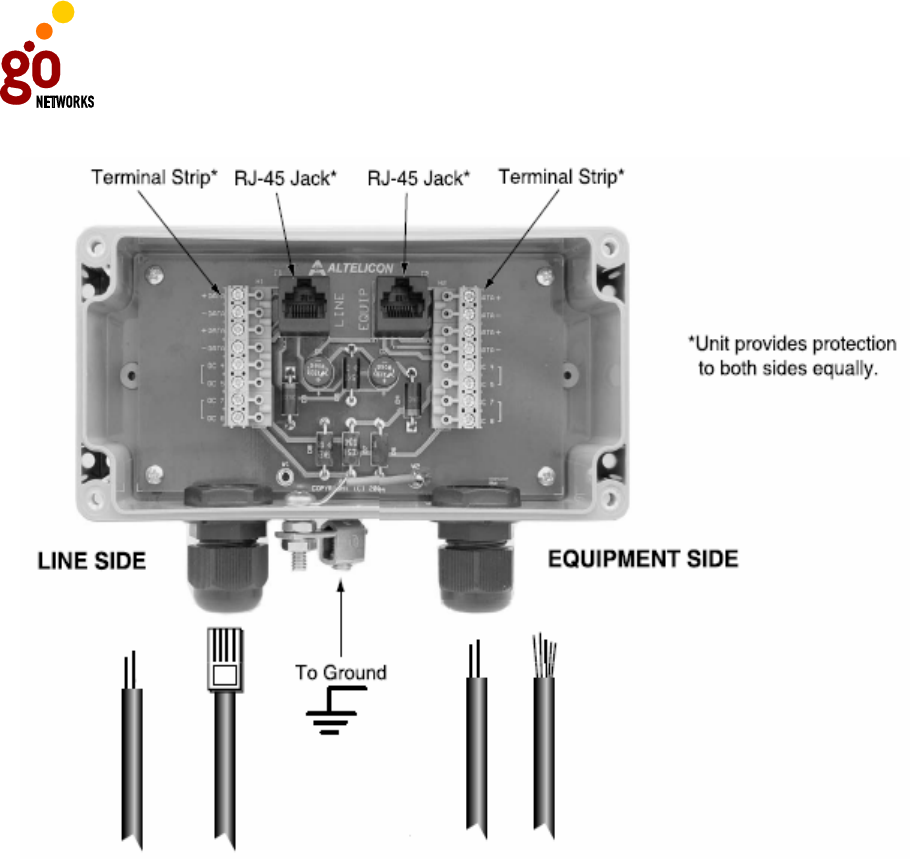
Verify that you have a shared grounding as shown in the diagram above. GO
Networks offers a lightning protector that can be ordered separately. Details of how
the lightning protector is connected to the WLS unit (on the Equipment Side), and
the router or switch (on the Line Side) are shown in the diagrams in the following
sections.
WLS Component and Cable Connections
Because cable requirements are often unique to the location and deployment
topology of each installation, power and Ethernet cables are not included in the
installation kit. In order to install the WLS unit, the following cables should therefore
be obtained:
GO MBW Getting Started Guide
GO MBW Getting Started GuideGO MBW Getting Started Guide
GO MBW Getting Started Guide
Draft Version - Confidential - Page 17
• Ethernet cable: CAT5 shielded; maximum length: up to 100 meters.
• Power cable: Standard power cable with a maximum length of up to 120
meters, supporting up to 48V and able to withstand outdoor conditions.
Note: Regional regulations vary. Therefore it is recommended that
you supply cables that meet local requirements and match
the distances between the WLS installation location and the
power supply or router.
Ethernet Connection
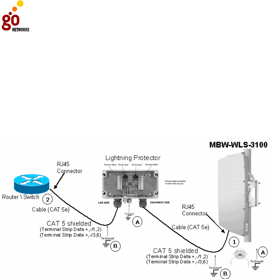
The following diagram illustrates how the WLS unit uses an Ethernet connection to
the router/switch via the lightning protector.
GO MBW Getting Started Guide
GO MBW Getting Started GuideGO MBW Getting Started Guide
GO MBW Getting Started Guide
Draft Version - Confidential - Page 18
2
Verify that you have a shared grounding as shown in the diagram above.
In the above diagram:
1 Indicates the connection that is made between the WLS and the lightning
protector. In this case, an RJ45 connector (supplied with the unit) is used.
A CAT5 shielded cable stretches between the WLS unit and the lightning
protector.
2 Indicates the CAT5 shielded cable and its connection to the Router/Switch,
which is also accomplished with an RJ45 connector.
A Indicates shared grounding for the building.
B Indicates shared grounding for the cable.
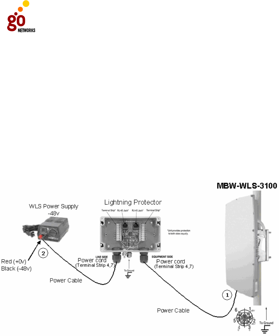
Power Connection
The following diagram illustrates how the WLS unit should be connected to the power
supply via a lightning protector.
Verify that you have shared grounding connected to both the lightning protector and
the WLS unit.
In the above diagram:
1 Indicates the two sides of the power cable connection between the WLS unit
and the lightning protector. The power connector is included in the WLS
package. Use a screwdriver to connect the power cables from both the

GO MBW Getting Started Guide
GO MBW Getting Started GuideGO MBW Getting Started Guide
GO MBW Getting Started Guide
Draft Version - Confidential - Page 19
power supply and from the WLS to the lightning protector via the terminal
strips.
2 Indicates the connection from the lightning protector to the power supply.
2
Installation Process
Installing the WLAN Sector Base Station involves the following steps:
• Performing a site survey
• Infrastructure development
• Installation of hardware and connectors
• Power up and software configuration
• Brief testing process to verify connectivity and operation
Site Survey
Most wireless LANs include many access points installed in various locations in an
overlapping radio-cell pattern. It is important to carefully position each access point's
positioning and the assignment of its radio channels. Therefore, a site survey
becomes an essential first step before physically deploying the GO MBW solution.
Installation of the access points requires a distribution system, such as Ethernet, to
interface the access points to the corporate network or Internet. Part of the site
survey should include a detailed understanding of changes that may need to be
made to the site (selecting and/or installing poles, for example).
Recommended Site Requirements
It is highly recommended that the WLS unit(s) be mounted near the edge of the roof
of a tall building (preferably the tallest building in the area). The WLS unit should be
pointed in the direction of the area to be covered. To provide maximum coverage,
multiple WLS units can be installed on the same rooftop. However it is important to
leave some distance between each unit in order to prevent interference between the
units themselves. When choosing the ideal location, it is also important to take into
consideration the overall area topology.
For more information, please consult with your GO Networks representatives.
Infrastructure Development
Infrastructure development is likely to vary depending on location. In general, this
step would include preparing the locations where the WLS units will be installed. This
may include laying cables and locating an electricity source close to where the WLS
unit will be installed.
GO MBW Getting Started Guide
GO MBW Getting Started GuideGO MBW Getting Started Guide
GO MBW Getting Started Guide
Draft Version - Confidential - Page 20
Hardware and Connectors Installation
There are two methods for mounting the WLS unit:
• On an outer wall (typically on a roof or high location to avoid interference from
other buildings or trees).
• On a pole (again, on a roof or high location).
Wall Mount
GO Networks has an optional adapter that enables the WLS
unit to be installed on a wall.
For more information, contact your local GO Networks
representative.
Pole Mount
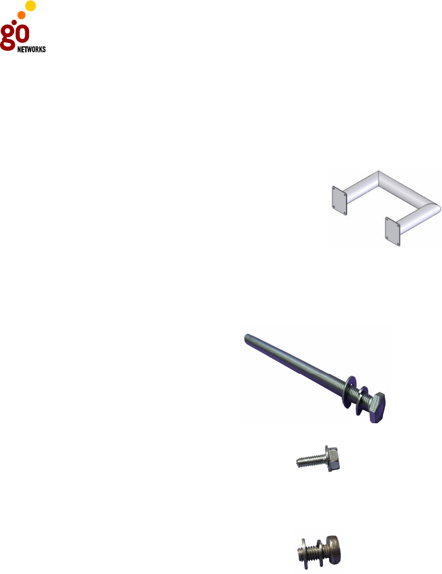
The contents of the Pole Mount kit includes:
Qty
Item
1 Installation Instructions for WLAN
Sector Base Station Pole Mount
4 Hex Cap Screw f DIN933 M10x180
ST ST A2
4 Flat Washer ST ST M10
4 Spring lock wash ST ST M10
4 Hex Ribbed Flange Bolt M6X16 Steel
Zinc Plated
6 Pan Head Phil. ST ST Screw M5x10
6 Washer Flat ST ST M5
6 Washer Spring ST ST M5
1 Turn Bracket
1 Post Bracket
1 Rear Post Bracket
NOTE: Unless otherwise indicated, all elements are stainless steel.

GO MBW Getting Started Guide
GO MBW Getting Started GuideGO MBW Getting Started Guide
GO MBW Getting Started Guide
Draft Version - Confidential - Page 21
Tools and Equipment Required
To mount the WLS on the wall, you will need the following tools and equipment.
Power connector crimp
tool
Screw driver – Philips
(size 2)
Ratchet (10 mm. and 17
mm.)
10 mm. 17 mm.
RJ45 crimp tool
HT-210A
Console cable
To mount the unit on a pole:
1. Select a convenient mounting location on the pole.
NOTE: When mounting the WLS on a pole, it should be placed on a
pole that can support four times the weight of the WLS (as in
the wall mount), as well as the wind loading created by the
WLS (maximum of about 470 kg for wind velocity of 200
km/h).
Noter: En installant le WLS sur un pole, il doit être place sur un pole
qui peut soutenir 4 fois le poids le poids du WLS ( comme
dans le pendage mural). Ainsi que la charge du vent crée par
le WLS (un maximum de 470 kg pour une vélocité de vent
égal a 200 km/h).
Power
GO MBW Getting Started Guide
GO MBW Getting Started GuideGO MBW Getting Started Guide
GO MBW Getting Started Guide
Draft Version - Confidential - Page 22
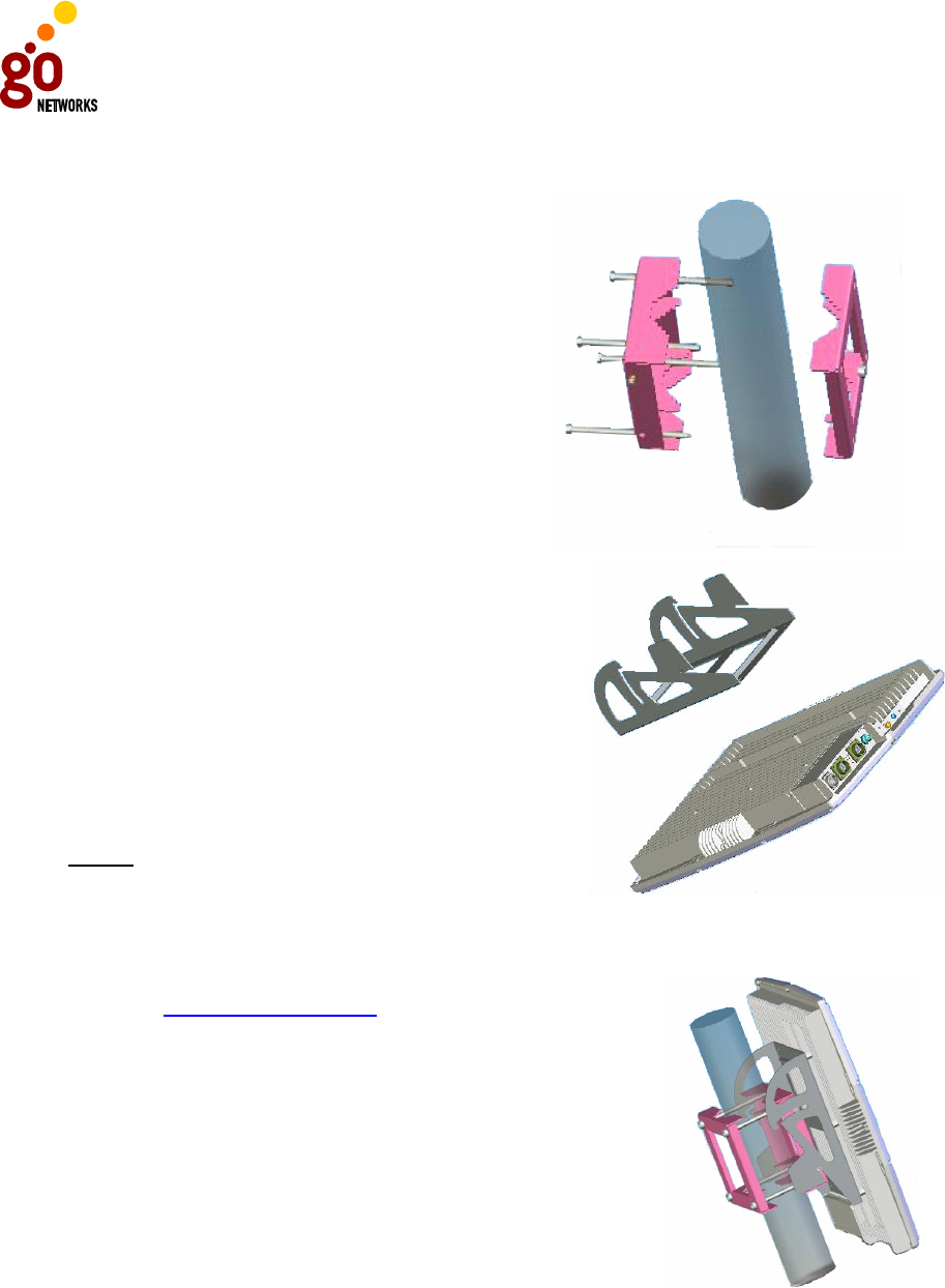
2. Place the two brackets around the pole at the approximate height where you
wish to place the unit.
3. Insert the four screws through both
brackets and tighten them around the
pole so that the two brackets are
securely fastened.
4. Attach the WLS unit to the mounting
bracket with six screws. Tighten the
screws so that the bracket and the
WLS unit are securely connected. The
connectors should be on the bottom of
the unit when it is attached to the
bracket.
5. Slide the WLS/mounting bracket onto
the pole brackets. You can adjust the tilt
of the bracket mount to enhance the
coverage and bypass interference for the
WLS unit.
NOTE: Before completing the
installation, you should
connect the grounding and
power cables. The grounding
cable should be connected to
the grounding screw.
Noter: Le cable de la masse doit etre
connecte au visse de la
masse.
The unit is now safely mounted to the wall. See the
section on Cable Connections for information on how
to connect and start the unit.
When the unit is correctly connected, the Power LED
will be green, as will the Status LED. The Activity LED
will be blinking green to indicate traffic is flowing
through the WLS. See the section on LED Indicators for
more information.
GO MBW Getting Started Guide
GO MBW Getting Started GuideGO MBW Getting Started Guide
GO MBW Getting Started Guide
Draft Version - Confidential - Page 23
Cable Connections
The WLS unit connections are very simple and can be accomplished in only a few
minutes. When mounted, the WLS should be installed with the connecters at the
bottom of the unit. Before completing the installation, you should connect the power
and grounding cables.
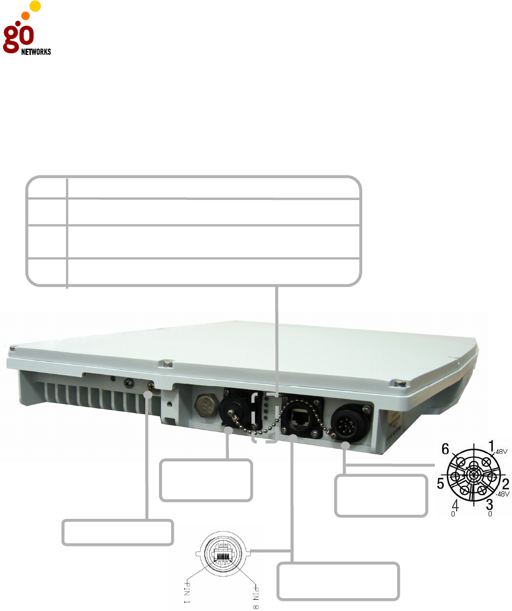
Connection Panel on WLS
Consol Port:
RS23
2
Power Port:
-
48v
connector
Ethernet
Interface:
10M/100M
Grounding Screw
LED
Green
There is power to the unit.
Unlit:
There is no power to the unit.
Power
Green
The WLS unit is operational.
Red
Status LED is still red, contact technical support.
Statu
Green
Traffic is flowing through the WLS unit.
Unlit:
No traffic is flowing.
Activity
Not used in current version.
Blank
The WLS
-
in tests have failed. Restart the unit. If the
GO MBW Getting Started Guide
GO MBW Getting Started GuideGO MBW Getting Started Guide
GO MBW Getting Started Guide
Draft Version - Confidential - Page 24
The order in which the cables should be connected is as follows:
• Grounding Cable
• Ethernet Cable
• Power Cable
Grounding Cable
Note: The grounding cable should be connected to the grounding
screw. For the grounding cable, you should use a 1mm /
18awg. You should connect the grounding cables before any
other connections.
Noter: Le câble de la masse doit être connecte au visse de la masse.
Pour le câble de la masse vous devez utiliser un 1mm /
18awg. Vous devez connecter le câble de la masse avant tout
autre connexion.
Ethernet Cable Connection
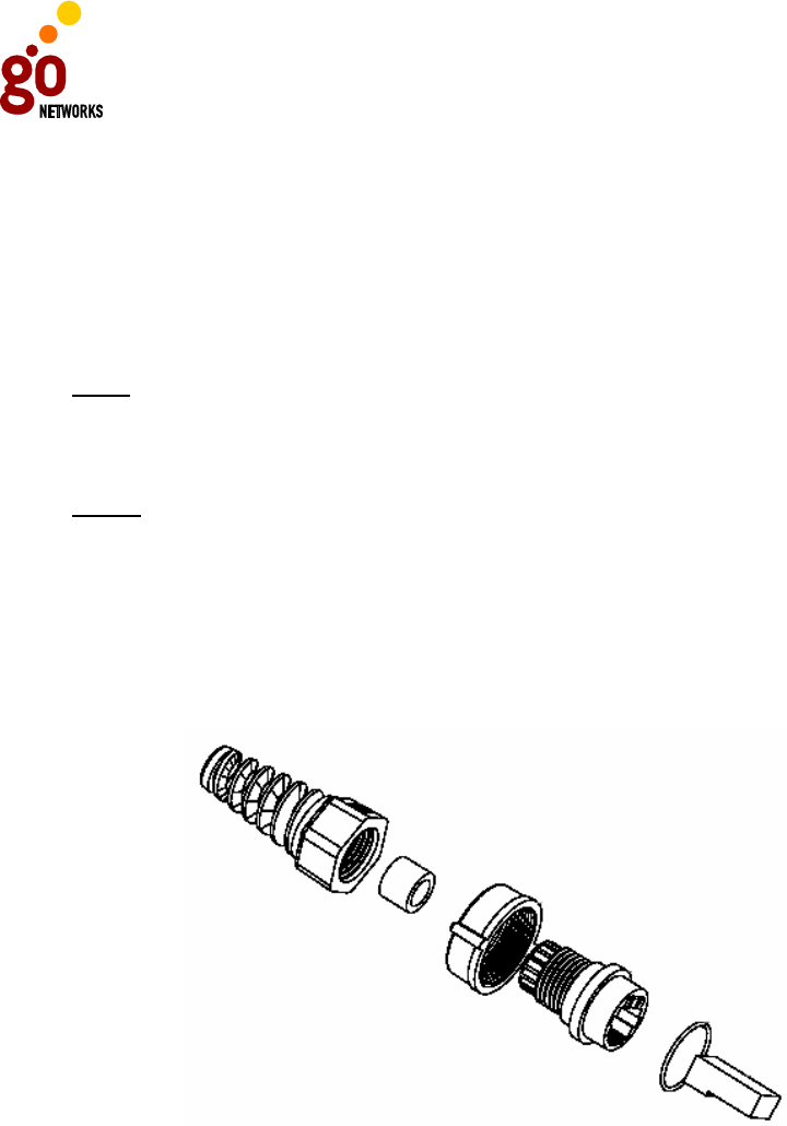
Following is a diagram explaining how the Ethernet cable should be assembled prior
to connecting it to the WLS unit:
Ethernet Cable Connector
The Ethernet cable should be connected to an Ethernet switch, ADSL or cable
modem, according to the site installation requirements. The outer diameter of the
Ethernet cable should be 4.8 – 7 mm.
In an outdoor installation, the Ethernet cable should be connected to a lightning
protector. The lightning protector is then connected to the Ethernet switch, ADSL or
cable modem. GO MBW recommends the GO MBW WLAN Sector Base-Station-3001,
(a weather-proof, point-of-entry, 10/100 Base-T CAT5 Lightning Protector), which
can be ordered as an optional accessory of the GO-MBW package.
GO MBW Getting Started Guide
GO MBW Getting Started GuideGO MBW Getting Started Guide
GO MBW Getting Started Guide
Draft Version - Confidential - Page 25
Power Cable Connection
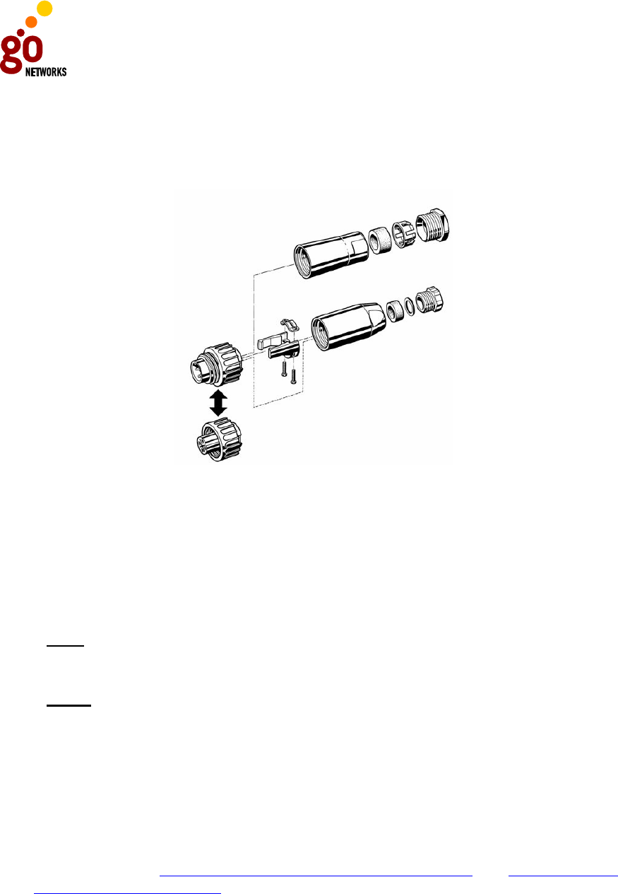
Following is a diagram explaining how the power cable should be assembled prior to
connecting it to the WLS unit:
Power Cable Connection
The power cable should be connected to a power supply unit. If there is already a -
48V power supply on site the WLS can be connected to it without the power supply
unit (PSU).
Depending on which cable you use, the following parameters should be applied:
• For 0.5mm 24awg with 2 tendon: each side can be up to 60m.
• For 1mm 18awg with 1 tendon: each side can be up to 120m.
Note: The power cable should be at least 14mm in diameter
(including insulation) and should be routed through a conduit
of at least 20mm diameter.
Noter: Le câble d’alimentation doit être d’au moins 14mm de
diamètre (isolation comprise), et doit être achemine a travers
un conduit d’au moins 20 mm de diamètre.
Power Up and Software Configuration
Configuration of the WNC unit is typically done once it is already installed. Because
the WLS unit is mounted on a roof or similar location, configuration of the unit is
typically done before mounting. Once the unit is mounted, it should be powered up
and connectivity confirmed. For details on configuring both the WNC and the WLS,
see the sections: Configuring the Wireless Network Controller and Configuring the
WLAN Sector Base Station.

GO MBW Getting Started Guide
GO MBW Getting Started GuideGO MBW Getting Started Guide
GO MBW Getting Started Guide
Draft Version - Confidential - Page 26
Post Installation Testing Procedure
The purpose of the post-installation testing procedure is to verify connectivity
between the WLS and the WNC units to enable Internet services to client stations.
Once the WNC has been installed, connectivity with the router/switch should be
verified. This will enable the WNC to communicate with the Radius server as well as
the WLS.
Once the WLS has been installed and configured, connectivity to the WNC should be
verified. In addition, connectivity between the client stations and the WLS should be
verified.

GO MBW Getting Started Guide
GO MBW Getting Started GuideGO MBW Getting Started Guide
GO MBW Getting Started Guide
Draft Version - Confidential - Page 27
Configuring the WNC
Following is a brief overview of the main CLI commands that are used to configure
the WNC. A configuration example follows the detailed list of configuration
commands. These and other CLI commands are detailed in the GO MBW CLI
Reference Guide.
Connect and Access the Wireless Network Controller (WNC)
In order to connect and access the Wireless Network Controller, you must first
connect with console (9600 rate, bit 8, data bit 1, stop bit) or you can also access
the WNC by using telnet application: (access the MNG interface using: ip address
192.168.0.1).
You can connect to the WNC using a laptop or standard computer. Using an Ethernet
cross cable connected to your laptop, connect the Ethernet network interface of the
laptop to the WNC’s MNG interface.
You can then access the login screen and login with an authorized user name and
password.
The factory default super user name is: super
The factory default password is: super
Once you login, you can then configure the WNC as follows:
Step1: Configure the Access Interface
The ACCESS interface is the gateway used to for the connection from the WLS to the
WNC.
Define the static IP address and the subnet mask on the same network to which you
connect the ACCESS interface by using the following parameter:
configure interface fastethernet ACCESS [IP] [netmask] [bcast]
Step 2: Configure the Net Interface
The NET interface is the gateway for outside Internet connection to the
Intranet/Internet world.
Define the static IP address and the subnet mask on the same network to which you
connect the NET interface. To accomplish this, use the following parameter at the
boot level:
configure interface fastethernet NET [IP] [netmask] [bcast]
Step 3: Configure the Default Gateway

GO MBW Getting Started Guide
GO MBW Getting Started GuideGO MBW Getting Started Guide
GO MBW Getting Started Guide
Draft Version - Confidential - Page 28
Define the default gateway IP address on the same networking on which you connect
the NET interface. To accomplish this, use the following parameter:
configure ip default-gateway <ip address>
Step 4: Configure the DHCP Server
By default, the DHCP server is already defined. To create the IP range for the DHCP
Server, use the following parameter at the boot level:
configure ip dhcp pool add [<name> <start-address> <end-address>
<pool-netmask> <lease-spec>]
Step 5: Configure the DNS
To be able to surf the Internet, you will need to configure at least one DNS relay list
by using the following parameter at the boot level:
configure ip dns fwd-list <ip address list>
Additional DNS can be added to the list using a semi-colon separation. For example:
configure ip dns fwd-list 192.168.1.1; 192.168.2.1
Step 6: Configure the Radius Authentication Client Connectivity
Define the authentication Radius server IP address on the client in the WNC using
the following parameter at the boot level:
configure radius-client auth-primary-server-ip <ip address>
Step 7: Configure the Radius Authentication Shared Key
Define the authentication secret password Radius server IP address on the client in
the WNC, using the following parameter:
configure radius-client auth-primary-server-secret <string>
Step 8: Configure the Radius Authentication Port Connectivity
By default the port number of the authentication is 1812. To define the port number
of the Radius server on the client in the WNC, use the following parameter at the
boot level:
configure radius-client auth-primary-server-port <port-number>
Step 9: Configure the Radius Authentication Source IP Address
You should define the authentication source IP address of the client in the WNC by
using the following parameter at the boot level:
configure radius-client auth-source-ip <IP address>
Step 10: Configure the Radius Accounting Client Connectivity

GO MBW Getting Started Guide
GO MBW Getting Started GuideGO MBW Getting Started Guide
GO MBW Getting Started Guide
Draft Version - Confidential - Page 29
You should define the accounting Radius server IP address of the client in the WNC
by using the following parameter at the boot level:
configure radius-client acct-primary-server-ip <IP address>
Step 11: Configure the Radius Accounting Shared Key
Define the accounting secret password Radius server IP address of the client in the
WNC, by using the following parameter at the boot level:
configure radius-client acct-primary-server-secret <string>
Step 12: Configure the Radius Accounting Port Connectivity
By default, the port number of the accounting is 1813. To define a different port
number for communication between the Radius server and the client in the WNC, use
the following parameter at the boot level:
configure radius-client acct-primary-server-port <port-number>
Step 13: Configure the Radius Accounting Source IP Address
Define the accounting source IP address of the client in the WNC by using the
following parameter at the boot level:
configure radius-client acct-source-ip <IP address>
Step 14: Update Radius Settings
To apply the Radius configuration changes and update the configuration changes you
have made, use the following parameter at the boot level:
configure radius-client apply-radius-changes
Step 15: Save the Configuration
Once you have modified the existing configuration file, you should save it for future
use. To do this, issue the following CLI command at the boot level:
copy running-config startup-config

GO MBW Getting Started Guide
GO MBW Getting Started GuideGO MBW Getting Started Guide
GO MBW Getting Started Guide
Draft Version - Confidential - Page 30
WNC Configuration Example
wnc > Configure interface fastethernet ACCESS 192.168.30.101
255.255.255.0 192.168.30.255
wnc > Configure interface fastethernet NET 192.168.31.101
255.255.255.0 192.168.31.255
wnc > configure ip default-gateway 192.168.31.254
wnc > configure ip dhcp pool add users 192.168.30.1 192.168.30.100
255.255.255.0 5h
wnc > configure ip dns fwd-list 194.90.1.5
wnc > configure radius-client auth-primary-server-ip 192.168.31.99
wnc > configure radius-client auth-primary-server-secret 12345
wnc > configure radius-client auth-primary-server-port 1645
wnc > configure radius-client auth-source-ip 192.168.31.101
wnc > configure radius-client acct-primary-server-ip 192.168.31.99
wnc > configure radius-client acct-primary-server-secret 12345
wnc > configure radius-client acct-primary-server-port 1646
wnc > configure radius-client acct-source-ip 192.168.31.101
wnc > configure radius-client apply-radius-changes
wnc > copy running-config startup-config
GO MBW Getting Started Guide
GO MBW Getting Started GuideGO MBW Getting Started Guide
GO MBW Getting Started Guide
Draft Version - Confidential - Page 31
Configuring the WLS
Following is a brief overview of the main CLI commands that are used to configure
the WLS. A configuration example follows the detailed list of configuration
commands. These and other CLI commands are detailed in the GO MBW CLI
Reference Guide.
Connect and Access the WLS
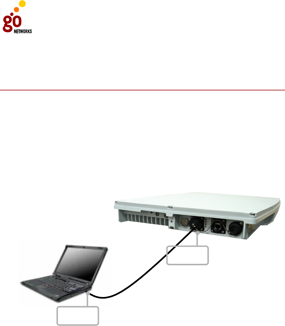
You can connect to the WLS using a laptop or standard computer. Using an RS232
interface DB-9 cable, connect the COM port of the laptop to the WLS unit’s consol
port. For more information, see Appendix A, Wiring Specifications.
Notebook PC
Consol Port:
RS232
Consol Port:
RS232
Consol Port:
RS232
Consol Port:
RS232
WLS
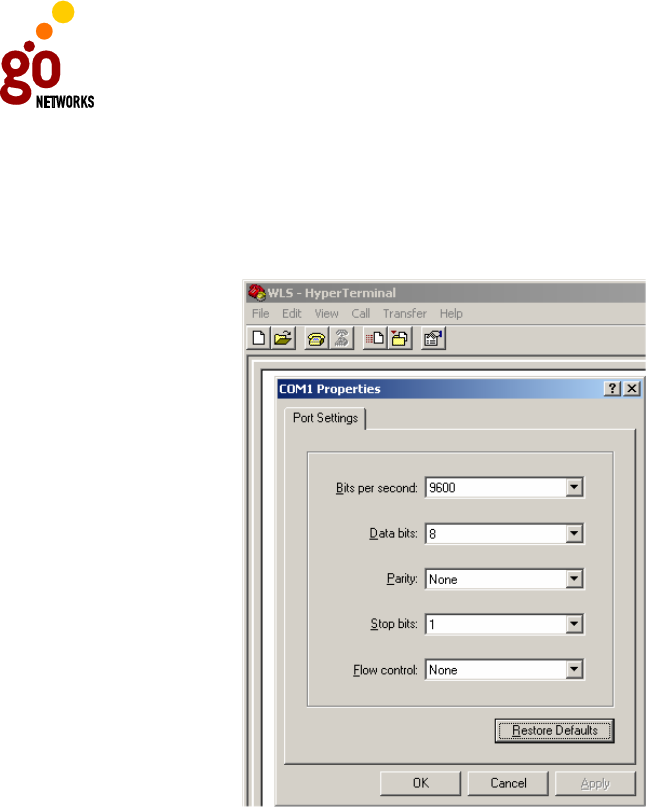
Once connected, you can then operate a terminal program, such as HyperTerminal,
to configure the WLS unit to the following specifications:
• Baud rate = 9600
• Data bits = 8
• Parity = none
• Stop bits = 1
GO MBW Getting Started Guide
GO MBW Getting Started GuideGO MBW Getting Started Guide
GO MBW Getting Started Guide
Draft Version - Confidential - Page 32
To use HyperTerminal:
From the Start menu, select All Programs > Accessories > Communications >
HyperTerminal. Once you have defined a new connection, right-click and select
Properties. You should then set or verify the above values.
After the connection between the WLS and the laptop (or PC) is established, you will
need to enter your user name and password. Your user name determines what
authorization level you have and in turn determines whether you can view
configuration and operation parameters, or implement changes. The default super
user name is Super and the default password is Super. A new user and password
name should be added, however this default name and password can be used for the
initial configuration. The default system name for the unit is set to WLS.
Step 1: Configure the Fast Ethernet Interface
Define the static IP address and the subnet mask on the same network through
which you connect to the WLS. You can use the CLI command:
configure interface FastEthernet 0 ip address <ip address>, as
shown below:
configure interface FastEthernet 0 ip address 192.168.30.102
255.255.255.0
The default is DHCP mode.

GO MBW Getting Started Guide
GO MBW Getting Started GuideGO MBW Getting Started Guide
GO MBW Getting Started Guide
Draft Version - Confidential - Page 33
Step 2: Configure the Default Gateway
Define the default gateway by using configure mode (consult with your network
administrator). You can use the CLI command configure ip default-gateway
<ip address> disable/enable, as shown below:
configure ip default-gateway 192.168.30.254
Step 3: Configure the Dot11Radio interface
By default the channels are configured (ch1, ch6). You can define different
configuration for each channel by using following CLI command:
configure interface dot11Radio 0 channel 1
Step 4: Configure the ESSID
ESSIDs are case sensitive and can contain up to 32 alphanumeric characters. They
should not include spaces. By default, the ESSID is GoAP. You can change the
default for each channel by use the following CLI command syntax:
configure interface dot11Radio [0|1] essid <ssid string>
Step 5: Set Radio Data Rates
By default the channels are defined for use in a mixed mode. You can select a rate
per channel for one of two states: g or mixed (a combination of g and b). The
following CLI command syntax is used:
configure interface dot11Radio [0|1] mode [g | mixed]
Optional Step: Set WEP Privacy Mode
By default the WEP privacy is disabled. To enable privacy encryption, you can use
the following CLI syntax:
configure interface dot11Radio [0|1] wep enable open [40|128] hex
<index integer (1-4)> <key string>
Step 6: Enable the Radio Interface
By default, the WLS radio is disabled. You can, however, choose to enable it using
the following CLI command syntax:
configure interface Dot11Radio [0|1] [disable | enable ]
Step 7: Save the Configuration
Once you have modified the existing configuration file, you should save it for future
use. To do this, issue the following CLI command:
copy running-configure startup-configure

GO MBW Getting Started Guide
GO MBW Getting Started GuideGO MBW Getting Started Guide
GO MBW Getting Started Guide
Draft Version - Confidential - Page 34
WLS Configuration Example
wls > configure interface FastEthernet 0 ip address 192.168.30.102
255.255.255.0
wls > configure ip default-gateway 192.168.30.254
wls > configure interface dot11Radio 0 channel 1
wls > configure interface dot11Radio 0 essid Test
wls > configure interface dot11Radio 0 mode mixed
wls > configure interface dot11Radio 0 enable
wls > configure interface dot11Radio 1 channel 6
wls > configure interface dot11Radio 1 essid Test
wls > configure interface dot11Radio 1 mode mixed
wls > configure interface dot11Radio 1 enable
wls > copy running-config startup-config

GO MBW Getting Started Guide
GO MBW Getting Started GuideGO MBW Getting Started Guide
GO MBW Getting Started Guide
Draft Version - Confidential - Page 35
Upgrading the WLS Software
The following section describes how to update the WLS software. Periodically, new
software upgrades are released in order to provide feature enhancements and
maintenance. Following is one method you can use to update the software:
• Initiate the network download using a TFTP download server.
Note: The WLS unit has two banks in the Flash memory (sw0,sw1).
By default, the WLS will startup the software image from the
sw1 bank.
Initially, when you download the new software image, the older version is
automatically transferred to sw0 bank, and the new software image is transferred to
sw1 bank.
Upgrade Example
wls>
wls> import image from tftp [IP ADDRESS] [File Name]
wls> show messages software-download
Software download started.
Verifying server and path.
TFTP path OK.
Flash erase started.
Flash erase finished.
Download started from 192.168.30.103 gapsw-1.3.5.11995-Beta-28.02.2006@180244.img.
Download finished.
Verification started.
Verification passed.
Writing to environment.
Software download finished.
Note: It is important to reload the system after upgrading the WLS
software for the changes to be applied and the new software
to become operational.

GO MBW Getting Started Guide
GO MBW Getting Started GuideGO MBW Getting Started Guide
GO MBW Getting Started Guide
Draft Version - Confidential - Page 36
You may need to copy a new image to the Flash memory whenever a new image or
maintenance release becomes available.
To copy a new image into Flash memory (write to Flash memory):
• Use the import image from tftp command.
• The system is now ready to be reloaded. After reload, the system will operate
with the new image.

GO MBW Getting Started Guide
GO MBW Getting Started GuideGO MBW Getting Started Guide
GO MBW Getting Started Guide
Draft Version - Confidential - Page 37
Troubleshooting
Problem:
The Captive Portal does not appear on the client’s screen.
Solution:
• Check the DNS Forward List to verify that the IP address of the ISP is included.
• If the DNS is not there, issue the following command:
configure ip dns fwd-list <ip address list>
• Check the connectivity between the WNC and the ISP by issuing the following
command: ping <ip address>. If you do not receive a ping response,
check the routing table with your ISP.
Problem:
User authentication fails and client is unable to access the Internet.
Solution:
• Confirm that the user name and password are correctly defined on the Radius
server.
• Check the Radius server’s client configuration Use the following command to
show the client configuration: show radius server settings.
• Check the connectivity between the WNC and the Radius server by pinging the
Radius server.
• Check that the shared key on the WNC is the same as the shared key on the
Radius server by reviewing the Radius server logs (review the section which
lists failed actions and check whether the key is the same on both the WNC
and Radius sides).
Note: All changes to the WNC configuration related to the Radius
server must be followed by applying and saving the changes
using the command:
configure radius-client apply-radius-changes
Problem:
System fails to recognize start or end of session for accounting purposes.
Solution:
• Check the WNC configuration and the Radius server configuration.
• Check connectivity with the Radius server.

GO MBW Getting Started Guide
GO MBW Getting Started GuideGO MBW Getting Started Guide
GO MBW Getting Started Guide
Draft Version - Confidential - Page 38
• Check the port application used to communicate between the WNC and the
Radius server.
• Check that the shared key on the WNC is the same as the shared key on the
Radius server by reviewing the Radius server logs (review the section which
lists failed actions and check whether the key is the same on both the WNC
and Radius sides).
Note: All changes to the WNC configuration related to the Radius
server must be followed by applying and saving the changes
using the command:
configure radius-client apply-radius-changes
Problem:
The client doesn’t see any ESSID options for selecting a wireless network.
Solution:
• Check whether the option for wireless communication is disabled (the default
setting) on the WLS unit.
• Check the ESSID configuration and issue the following command, if needed:
configure interface dot11Radio essid <ssid string>
Problem:
After installing the lightning protector, no communication between the WLS and the
WNC is established.
Solution:
• Check cable connections between WNC and the lightning protector, the WLS
and the lightning protector, and each of the power cables.
Problem:
A connection error is received, including: dropping packets, error bit packet, CRC
error, or the WLC can’t establish a link with the WNC.
Solution:
• Check the lengths of the cables: the Ethernet cable must be less than 100
meters in length)
• Check the grounding connection to confirm it is a continuous connection
between the WLS and the WNC.
• Check the wiring on the RH45 connectors.
• Check the cables themselves to verify their physical integrity (that they are
not cut or crushed or blocked in some other way).

GO MBW Getting Started Guide
GO MBW Getting Started GuideGO MBW Getting Started Guide
GO MBW Getting Started Guide
Draft Version - Confidential - Page 39
Problem
A continuous beeping sound is heard after the WNC unit is plugged into the power
source.
Solution:
When only one power supply is connected, the unit will beep continuously to indicate
the absence of power in the second connection. This indicates either a faulty AC
module, or the fact that one power supply has not been connected. To stop the
warning beep, either connect the second power supply, thus creating a redundant
power source, or disconnect the second power supply unit completely from the WNC
unit.

GO MBW Getting Started Guide
GO MBW Getting Started GuideGO MBW Getting Started Guide
GO MBW Getting Started Guide
Draft Version - Confidential - Page 40
Appendix A: Wiring Specifications
Table: Console Port Signaling and Cabling with a DB-9 Adapter for the WLS Unit
RTS 7 8 8 No
connection
DTR 4 7 7 No
connection
RxD 2 6 6 TxD
TxD 3 5 5 RxD
GND 5 4 4 GND
GND 5 3 3 No
connection
DSR 6 2 2 No
connection
CTS 8 1 1 No
connection
Signal DB-9 Pin
RJ-45
Pin
RJ-45
Pin
Signal
Console
Device
RJ-45-
to-DB-9
Terminal
Adapter
RJ-45-to-RJ-45
Straight Cable
Console
Port (DTE)

GO MBW Getting Started Guide
GO MBW Getting Started GuideGO MBW Getting Started Guide
GO MBW Getting Started Guide
Draft Version - Confidential - Page 41
RTS
7
8
CTS
CTS
8
7
RTS
DTR
4
6
DSR
GRD
5
5
GRD
DSR
6
4
DTR
RxD 2 3 TxD
TxD
3
2
RxD
DCD 1 1 No connection
Signal
DB
-
9 Pin
DB
-
9 Pin
Signal
Console
Device
RS232-to-RS232 Straight
Cable
Console Port
(DTE)
1
RTS = Request To Send
2 CTS = Clear To Send
3 TxD = Transmit Data
4 RxD = Receive Data
5 GRD = Ground
6 DTR = Data Terminal Ready
Table: Console Port RS232 DB-9 Pin for the WNC Unit