Gorman Redlich Co CAP-DEC1 CAP Converter User Manual CAP DEC 1 INSTRUCTION MANUAL
Gorman Redlich Manufacturing Co CAP Converter CAP DEC 1 INSTRUCTION MANUAL
Users Manual

Page 1 of 15
INSTRUCTION MANUAL
MODEL CAP-DEC 1
Common Alerting Protocol
Universal Intermediary Device
FCC ID: MVZ CAP-DEC 1
5.25.2012
v2.23 5-24-2012
GORMAN REDLICH
257 West Union St.
Athens, Ohio 45701
Ph: 740-593-3150 Fax: (740) 592-3898
www.Gorman-Redlich.com email: jimg@gorman-redlich.com
Page 2 of 15
FCC warning
Warning: Changes or modifications to this unit not expressly approved by the party responsible for
compliance could void the user authority to operate the equipment.
FCC Compliance Statement
This device complies with Part 15 of the FCC Rules. Operation is subject to the following two
conditions:
(1) This device may not cause harmful interference, and
(2) This device must accept any interference received including interference that may cause
undesired operation.
NOTE: This equipment has been tested and found to comply with the limits for a Class B digital device,
pursuant to Part 15 of the FCC Rules. These limits are designed to provide reasonable protection against
harmful interference in a residential installation. This equipment generates, uses and can radiate radio
frequency energy and, if not installed and used in accordance with the instructions, may cause harmful
interference to radio communications.
However, there is no guarantee that interference will not occur in a particular installation. If this equipment
does cause harmful interference to radio or television reception, which can be determined by turning the
equipment off and on, the user is encouraged to try to correct the interference by one or more of the
following measures:
• Reorient or relocate the receiving antenna
• Increase the separation between the equipment and receiver
• Connect the equipment into an outlet on a circuit different from that to which the receiver is
needed
• Consult the dealer or an experienced radio/TV technician for help
Page 3 of 15
WARRANTY
For a period of 1 year from date of shipment, Gorman-Redlich warrants the CAP-DEC 1 to be free
from defects in materials and workmanship and will repair or replace, at its option, any CAP-DEC 1
unit that fails in normal service without a charge for parts or labor and with a flat $25 fee, prepaid by
purchaser, to cover shipping and handling. Units can only be accepted for adjustment under
Warranty following notification by letter, telephone or e-mail. Units showing evidence of modification
or abuse, in the judgment of Gorman-Redlich, cannot be accepted for repair under Warranty, but
will be repaired for a reasonable fee, with the consent of the purchaser.
COMMON ALERTING PROTOCOL AND THE EMERGENCY ALERT SYSTEM
The Common Alerting Protocol (CAP) is an XML-based data format for exchanging public
warnings and emergencies between alerting technologies. CAP allows warning messages to be
distributed consistently and simultaneously across multiple warning systems. This protocol
allows for the inclusion of large amounts of information about emergency situations which can
range from general situational data to information intended for specific alerting platforms.
The Emergency Alert System (EAS) is a national warning system in the United States put into
place on January 1, 1997. In addition to alerting the public of local weather emergencies such as
tornadoes and flash floods, the EAS enables the President of the United States to address the
public on short notice via radio and television broadcast. EAS regulations and standards are
governed by the Public Safety and Homeland Security Bureau of the FCC. EAS has become
part of the Federal Emergency Management Agency's (FEMA) Integrated Public Alert and
Warning System (IPAWS) and is jointly coordinated by FEMA, the Federal Communications
Commission (FCC), and the National Weather Service (NOAA/NWS).
GENERAL DESCRIPTION OF MODEL CAP-DEC 1 UNIVERSAL INTERMEDIARY DEVICE
The Gorman-Redlich CAP-DEC 1 Universal Intermediary Device retrieves CAP formatted alert
files from various sources on the internet. These files are compared to a variety of standards and
specifications, including the CAP v1.2 standard, the FEMA IPAWS Profile and the EAS-CAP
Implementation Guide to ensure message validity as well as being filtered by location and
effective time period. Valid messages are then transformed into an EAS Specific Area Message
Encoding (SAME) formatted header and passed on, along with additional audio, to attached EAS
equipment for transmission in a similar fashion to EAS alerts received over the air.
Page 4 of 15
Front Panel
1. Intake ventilation grate
2. Universal Serial Bus (USB) port to the right of the ventilation grate
3. Red power LED labeled “POWER” to the right of the USB port
Side Panel
1. Exhaust ventilation grate
2. RS232 serial data port labeled “SERIAL PORT”
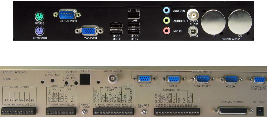
Rear Panel
1. PS/2 mouse port labeled “MOUSE”
2. PS/2 keyboard port labeled “KEYBOARD”
3. RS232 serial data port labeled “SERIAL PORT”
4. VGA video-out port labeled “VGA PORT”
5. Four (4) Universal Serial Bus (USB) ports labeled “USB 1” “USB 2” “USB 3” and “USB 4”
6. 10/100/1000 RJ45 ethernet port labeled “LAN”
7. 1/8-inch TRS line audio input jack labeled “AUDIO IN”
8. 1/8-inch TRS audio output jack labeled “AUDIO OUT”
9. 1/8-inch TRS microphone input jack labeled “MIC IN”
10. BNC alert audio connector labeled “ALERT AUDIO”
11. Barrel-type power jack labeled “12V 5A”
Page 5 of 15
The CAP-DEC 1 Intermediary Device
The FCC classifies Common Alerting Protocol (CAP) equipment into three categories: integrated devices,
universal intermediary devices and component intermediary devices.
The Gorman-Redlich CAP-DEC 1 unit is set to operate as a universal intermediary device. This means
that it will transform valid CAP alerts into EAS messages and output them as bursts of FSK data, attention
tone, message audio and EOM which can be input to a variety of EAS encoder/decoder devices. The
CAP-DEC 1c unit operates as a component intermediary device. This means that the unit will transform
valid CAP alerts into EAS messages and output them by means of a specialized data packet to a
compatible Gorman-Redlich EAS1 unit.
In most cases, users will have a CAP-DEC 1 universal intermediary device which is connected to their
EAS unit via an audio cable and requires no special updates for their EAS encoder/decoder. In sections of
this user guide where the differentiation is made between universal and component intermediary devices,
users should ensure that the appropriate set of instructions are followed.
Gorman-Redlich CAP-DEC 1 rear panel
Gorman-Redlich EAS1 Encoder/Decoder rear panel
Hardware Connections
Connections for Setup
Prior to using the CAP-DEC 1 unit, some minor initial setup must be performed to ensure proper operation.
This setup requires your interaction with the unit via normal PC interface hardware (e.g. keyboard, mouse,
monitor).
1. Connect a mouse using either a PS/2 connection to the MOUSE port or a USB connection to any of
the available USB ports on the rear of the CAP-DEC 1 unit.
2. Connect a keyboard using either a PS/2 connection to the KEYBOARD port or a USB connection to
any of the available USB ports on the rear of the CAP-DEC 1 unit.
3. Connect a monitor using a VGA cable to the VGA PORT on the rear of the CAP-DEC 1 unit.
4. Connect a network-attached ethernet cable to the RJ45 LAN port on the rear of the CAP-DEC 1
unit.
5. Power on the CAP-DEC 1 unit by attaching the 12V 5A AC adapter (labeled CAP-DEC 1 power
supply) to the power jack (labeled 12V 5A) on the rear of the CAP-DEC 1 unit and plug it in to the
power source.
Page 6 of 15
Unit Setup
Once the unit is powered up with the above connections, the CAP-DEC 1 unit may be configured as
desired to station-specific preferences including network setup, printer installation, monitoring and interface
options (e.g. logging devices), USB peripherals (e.g. flash drives), etc. (see Software Setup section below).
Due to the varied nature of such setup from one station to another, it is impossible to cover all possible
setup procedures. Manufacturer’s instructions should be followed for installation and use of devices such
as printers, USB drives, USB-to-RS232 adapters, logging devices or software, etc.
The CAP-DEC 1 unit must be configured for connectivity with your station’s specific network setup. Again,
due to the varied nature of such systems, it is impossible to cover all possibilities here. The steps
necessary to ensure CAP-DEC 1 connectivity mirror those required for any PC on your network. This
includes opening/unblocking ports for HTTP requests (default: 80) and SMTP activity if email functionality
is desired (default: 25). The CAP-DEC 1 executable (software) should be allowed access through station
firewall and other network protection. If your station’s network utilizes dynamic host control protocol
(DHCP), simply attaching the CAP-DEC 1 to the network should provide connectivity. If static IP
addressing is required, such settings may be entered by navigating to START | Control Panel and
searching for the View Network Connections option. Right-mouse-click the connection to be used and
choose Properties. Contact your station’s network technician for station-specific setup details.
Connections for Operation
Once the unit has been properly configured for operation, interface devices such as a keyboard, mouse
and monitor are not required for normal operation although they may be left attached for monitoring,
testing or further setup. The network cable must remain attached so that the unit is able to receive CAP
alerts and the power cable must remain attached. The following connections must be made to ensure
delivery of CAP-converted EAS alerts between the CAP-DEC 1 unit and the EAS decoder.
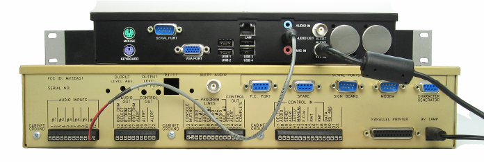
Connected Gorman-Redlich CAP-DEC 1 and EAS1 units
(universal intermediary device configuration)
Use as a Universal Intermediary Device
(With any certified EAS encoder/decoder, including Gorman-Redlich EAS1 products)
1. Connect the 1/8” TRS plug of the audio cable to the green AUDIO OUT port on the rear of the CAP-
DEC 1 unit. Install the red and black wires of the audio cable into the EAS unit on a channel
capable of monitoring for and parsing frequency shift keyed (FSK) EAS headers (see
encoder/decoder manufacturer documentation for details).
For Gorman-Redlich EAS1 units, the CAP-DEC 1 should be connected to the next available,
unscanned audio input. For example, if your EAS1 currently scans 5 inputs, the audio cable should
be connected to audio input #6 (terminals 11 and 12) as shown above.
Page 7 of 15
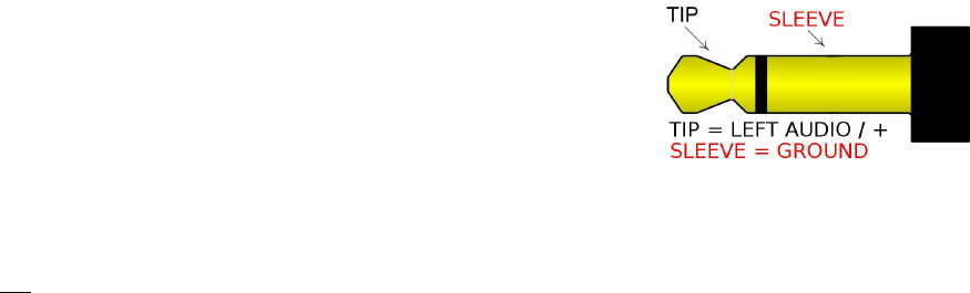
NOTE: Unlike the Gorman Redlich EAS1, some other manufacturers do not use a
transformer isolated balanced audio input. In the event the CAP-DEC 1 will be
connected to an encoder-decoder unit with an unbalanced input, check your audio
interconnect cable to make certain which of the conductors is connected to the
ground on the audio plug that you insert into the audio out receptacle on the CAP-
DEC 1.
Use as a Component Intermediary Device
(With Gorman-Redlich EAS1 encoder/decoder units with software v9.7 and above)
NOTE: Most users will not be using a CAP-DEC 1 as a component intermediary device
1. Connect the female end of the RS232 cable to the SERIAL PORT on the rear of the CAP-DEC 1
unit and the male end to the SPARE port on the rear of the EAS1 unit.
2. Connect the 1/8” TRS plug of the audio cable to the green AUDIO OUT port on the rear of the CAP-
DEC 1 unit. Install the red and black wires of the audio cable into the appropriate AUDIO INPUT
terminals (1-12) on the rear of the EAS1 unit (see EAS setup below for details on choosing the
correct audio input channel.
EAS1 Setup
Universal Intermediary Device Configuration
In the universal intermediary device configuration, the EAS encoder/decoder simply needs to be
configured to monitor the audio input channel into which the CAP-DEC 1 audio output is connected. For
Gorman-Redlich EAS1 encoder/decoders, this is achieved as follows:
1. Press the [MENU] key on the front panel of the EAS1 unit (button 7).
2. Enter the four-digit technician password.
3. At the Utility Menu screen, press the [DOWN ARROW] key to navigate to menu item 4 (SET
SCANNING) and press [ENTER].
4. Ensure that the audio channel to which the CAP-DEC 1 audio output is connected is being scanned.
5. Press the [EXIT/0] key to return to the utility menu, press the [UP ARROW] key to navigate to menu
item 3 (SET INPUT LEVEL) and press [ENTER].
6. Navigate to the audio channel to which the CAP-DEC 1 audio cable is connected and press
[ENTER].
7. Set the input level to 75 using the arrow keys and then press the [EXIT/0] key until you return to the
main screen with the clock displayed.
Page 8 of 15
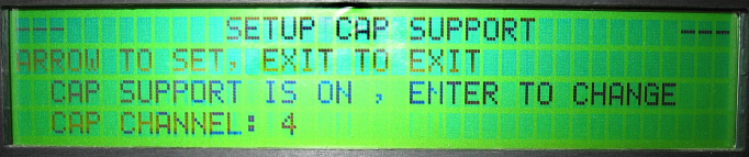
Component Intermediary Device Configuration
Gorman-Redlich EAS1 encoder/decoder display panel
Some setup is required of the EAS unit in order to receive CAP-translated EAS messages from the CAP-
DEC 1 via RS232.
Note: These steps are not required when operating the CAP-DEC 1 as a universal intermediary device
(AFSK tones). For universal intermediary device operation, CAP support should be set to OFF.
1. Press the [MENU] key on the front panel of the EAS1 unit (button 7).
2. Enter the four-digit technician password.
3. At the Utility Menu screen, press the [DOWN ARROW] key to navigate to menu item 14 (CAP
SETUP) and press [ENTER]. The menu above will be displayed.
4. Pressing [ENTER] here will toggle CAP-DEC 1 support ON or OFF. Ensure that CAP support is
ON.
5. The CAP channel will also be displayed. This channel corresponds to the AUDIO INPUT channel to
which the audio cable should be connected.
6. Press the [EXIT/0] key until you return to the main screen with the clock displayed.
Page 9 of 15
Software Setup
The CAP-DEC 1 software begins automatically once the unit has completed the boot-up process. The
software consists of two dialogs: the main software dialog and the configuration dialog.
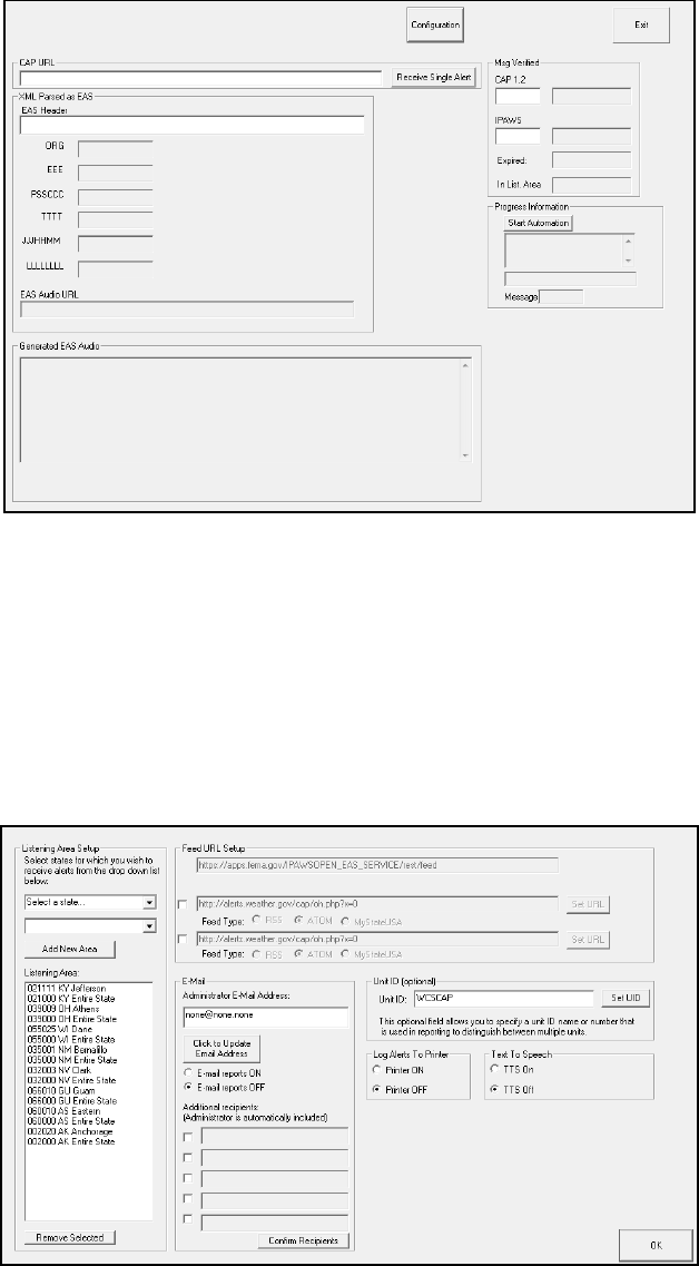
CAP-DEC 1 Main Software Dialog
The main software dialog contains information about and results from message processing as well as the
button to open the configuration interface.
The bulk of the CAP-DEC 1 software configuration is accomplished in the configuration dialog, which may
be reached by clicking the “configuration” button at the top of the main CAP-DEC 1 software dialog.
CAP-DEC 1 Software Configuration Dialog
Page 10 of 15
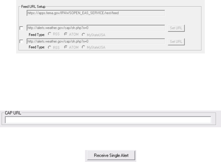
CAP Feed URLs – For Automated Operation
Depending on your state plan, you may be required to monitor more than one CAP alert server. The
Gorman-Redlich CAP-DEC 1 unit makes it easy for you to monitor one or more CAP alert server URLs.
These URLs and their options are setup in the “Feed URL Setup” area of the configuration dialog.
Enter the URL of the CAP feed that you wish to monitor into the first text box and click the button marked
“Set URL” to set the URL. Select the type of CAP alert feed that the URL is pointing to.
1. RSS – Select this option if the URL is for a Really Simple Syndication (RSS) feed.
2.
ATOM – Select this option if the URL is for an ATOM feed.
3.
MyStateUSA – Select this option to poll MyStateUSA feeds. MyStateUSA feeds should be entered in the format:
http://mystateusa.com/CapService.svc/GetEasFromStartDate/?username=USER&password=PASS
where USER and PASS represent the username and password provided to you by MyStateUSA.
The first URL, set to monitor the FEMA IPAWS message aggregator feed, is enabled by default and is not
user-editable. Enable a second or third CAP alert URL by marking the check-box next to the URL entry
field, entering a feed URL and clicking the “Set URL” button and selecting the feed type.
Feed URL Setup Controls
NOTE: If you know the URL(s) that you are required to monitor enter them on the programming sheet on the website and the unit’s URLs will be
preconfigured upon arrival.
Alert URL – Single Alert Operation
The CAP-DEC 1 is capable of being operated manually in manner which allows it to receive a single
message at a time. This functionality is achieved from the main software dialog.
1. Enter the web address (URL) of the single CAP alert to be retrieved and translated.
2. Click the Receive Single Alert button on the interface to begin processing of the alert.
Under most circumstances, users will not utilize this feature.
Page 11 of 15
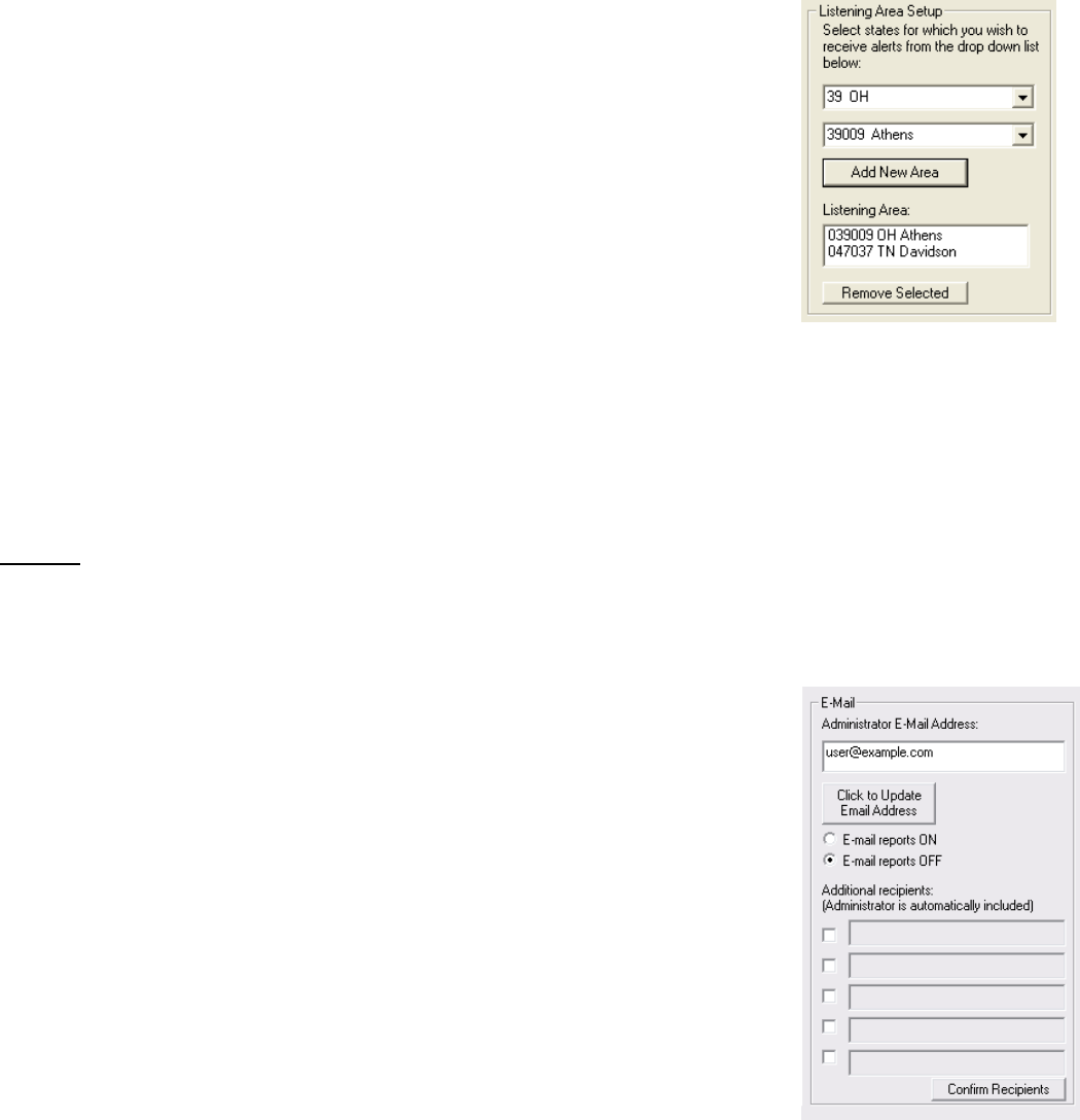
Listening Area Setup
The listening area for the device should be set up using the controls in the
“Listening Area Setup” area of the configuration dialog.
To set up area filtering, first select the state for which you wish to receive
alerts from the drop-down menu. Next, select the county you wish to add to
the listening area and click the “Add New Area” button to move that state
code to the list. You may add up to 50 individual counties to the listening
area list.
When a county from a new state is added to the CAP-DEC 1 listening area,
you will notice that an area called “Entire State” will also be added to the
listening area. See note below for more details on the “entire state” location
code as well as the CAP-DEC 1 listening area and how it behaves and how it
differs from the EAS encoder/decoder listening area.
To remove a state code from the filter list, highlight the code by clicking on it in the Listening Area list and
click the “Remove Selected” button below.
Note on CAP-DEC 1 Listening Area – The CAP-DEC 1 listening area is not necessarily the same as the listening area of an
EAS encoder/decoder. The CAP-DEC 1 will trigger on any valid (properly formatted, non-expired) CAP message in its listening
area and translate it into EAS header data and audio that is sent to a certified EAS encoder/decoder where it is filtered for
message validity and location as usual. The “Entire State” location code (comprised of the state FIPS prefix with a 000 county
code) does not mean that the CAP-DEC 1 will trigger on alert messages addressed to any county in that state. Rather, for a
message to be translated and forwarded under this code, the message must be specifically addressed to the entire state by
inclusion of the entire state location code as might be the case for a statewide governor-generated message.
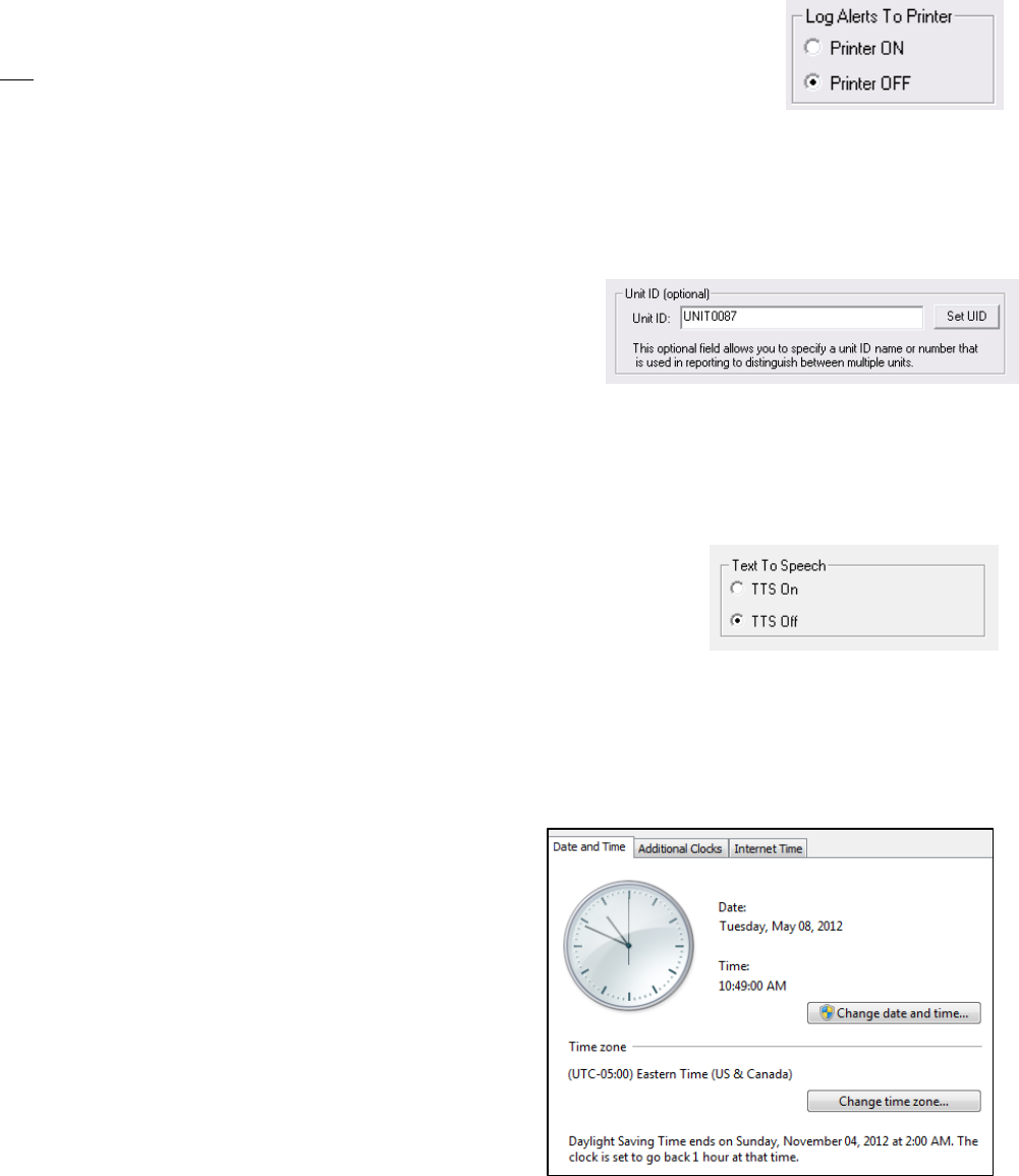
Email Setup
If you wish to receive emailed reports of the CAP alerts received by the unit:
1. Enter the email address you wish to use in the box marked
“Administrator E-Mail Address” and click the button labeled “Update
Email Address”. This email address will appear as both the sender
and the recipient of generated emails.
2. Mark the radio button for E-mail reports ON to enable email alerts.
3. To enable additional email recipients, mark the check-box next to the
first available address entry field and enter the e-mail address at
which you wish to receive reports. Click the “Confirm Recipients”
button to set the addresses as recipients.
To turn off email alerts:
1. Mark the radio button for E-mail reports OFF or enter
none@none.none in the administrator email address field and click
Update Email Address. Uncheck the box next to additional recipients to whom you no longer wish
to send reports.
NOTE: To help ensure that emails are received, be sure to add the administrator email address to your email client’s “trusted
senders” list.
Page 12 of 15
Print Setup
The option to have CAP alert reports logged to a printer is turned on or off via radio
buttons located in the Log Alerts to Printer group box in the display. The default
option is to not log alerts to a printer. For this option to function correctly a printer
must be correctly installed as specified as the default printer. The CAP-to-EAS
Decoder unit has built in support for thousands of USB printers; however, to ensure proper operation of
your printer, be sure to follow printer manufacturer's instructions for correct installation and setup.
NOTE To ensure printer compatibility with the CAP-DEC 1 unit, please ensure that your USB printer is Microsoft Windows 7 compatible.
Unit ID Setup
The optional Unit ID field allows you to specify a name or number
to identify a particular CAP-DEC 1 unit. The unit identification
appears in the printed and emailed reports to distinguish between
reports from multiple CAP-DEC 1 units.
To specify a Unit ID, type the desired identification information into the Unit ID field and click the “Set UID”
button.
Text to Speech Setup
The FCC Fifth Report and Order temporarily prohibited the use of text-to-
speech (TTS) technology on the receiving end of CAP alert messages.
This prohibition has since been reversed and the use of TTS is now
allowed.
Due to the initial uncertainty regarding the use of TTS, the CAP-DEC 1 interface allows the use of TTS to
be toggled on or off. As the prohibition has been lifted, TTS should remain ON.
Time Setup
To ensure correct calculation of alert expiration dates and
valid time periods, it must be ensured that the unit is
properly configured with the correct date, time and time zone
settings. To do this, left mouse click on the clock in the lower
right of the CAP-DEC 1 display and choose “Change date
and time settings…” From within the resulting display
(shown at right), ensure that the correct date, time and time
zone are set. After the initial setting, the unit will
automatically sync via the internet to ensure that the clock
stays accurate.
Page 13 of 15
Operation
Once the unit is properly configured as described above, the keyboard, video monitor and mouse used for
configuration is no longer required. These items, however, may remain connected for monitoring, future
configuration and local log access purposes. Monitoring and configuration may also be achieved by use of
an optional KVM switch or VNC technology (may require additional setup and/or hardware). Operation
begins automatically upon unit power-on and boot.
The CAP-DEC 1 will poll the specified CAP alert servers and attempt to process new alerts as described
below at a periodic interval. Alert summary logs, original XML CAP alert files and attached resource files
are stored locally in the CAPEAS directory of the storage device. Upon successful conversion from CAP
to EAS, the unit may print and/or email an alert report based on the unit’s settings. Note that these printed
reports may not satisfy EAS logging requirements.
Message Processing
Once an alert has been received (either from the feed during automated
operation or from a specific alert address), the CAP-DEC 1 will verify the alert’s
validity. First, the unit will verify that the message conforms to Common
Alerting Protocol v1.2 specifications IPAWS Profile specifications and EAS-
CAP Implementation Guide (ECIG) specifications. If the alert message passes
this verification step, the message expiration date is checked to ensure that the
alert is current. Finally, the targeted area of the alert is checked against the
listening area list. The results of these checks are displayed in the Msg
Verified group box on the user interface. If the message is invalid for any
reason, the first reason for failure will be displayed.
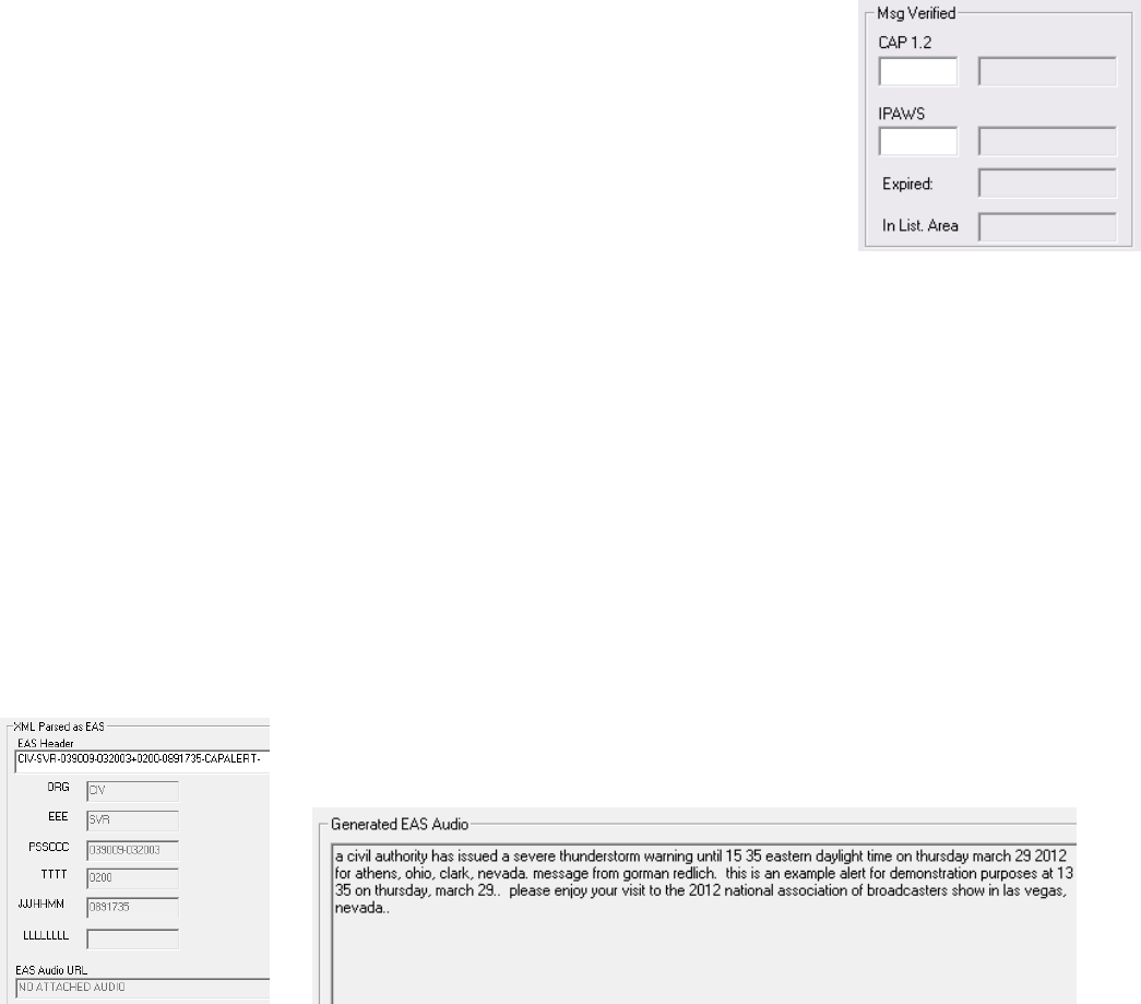
Message Success
If the message passes all of the above checks and it is not a duplicate message, it is then translated into
an Emergency Alert System (EAS) header as per the ECIG and transmitted, either as RS232 data (for
component intermediary device operation) or FSK data tones for universal intermediary device operation)
from the audio jack, along with any associated message audio. If no message audio file is associated with
the CAP alert and TTS is turned ON, the CAP-DEC 1 will render the CAP “enhanced text” as the audio
portion of the message.
The message information is then recorded to the CAP log file. The EAS header, along with the individual
fields of the header and the “enhanced text” are displayed on the user interface as shown below.
CAP to EAS message conversion information, including the constructed CAP “enhanced text”
Page 14 of 15
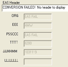
Message Failure
If the alert message fails the CAP conformity test, the unit will not attempt to
verify IPAWS conformity and this fact will be recorded in the log file. If it
passes the CAP verification but fails to create an EAS header, this will be
displayed in the EAS alert information area of the user interface as well as
noted in the log file.
Logging
In addition to the email and print summary logging capabilities described above in the setup section, the
CAP-DEC 1 maintains comprehensive local logs of its alert message activity. Logs are stored on the unit’s
main storage device in the CAPEAS directory. These logs may be accessed locally on the unit via
connected keyboard, display and mouse interfaces or over your local network from a PC connected to your
LAN (as network setups may vary, contact your station IT personnel to set up network file sharing access).
Navigate to
C:\CAPEAS
to access these files.
Summary Log
The main CAPEAS directory contains a file named log.txt which contains details about each message
received. These details include the CAP-DEC 1 unit ID (useful if you are maintaining logs for multiple
units), alert source, whether the alert passed CAP 1.2 and IPAWS Profile constraints, the unique alert
identifier, whether the alert is within the unit’s listening area, whether the alert is current or expired and
additional message details. The log also contains the path to a local copy of the original XML formatted
CAP message and any attached audio. If the message meets all constraints and is successfully converted
into an EAS message, the resulting EAS header string is also included in the log file entry.
Original Message Files
Within the main CAPEAS directory is a sub-directory named log. The log directory holds all of the original
XML formatted CAP messages that the unit receives regardless of the success or failure of converting
them to an EAS message. If the message includes an attached EAS audio file, it is also stored in this
directory. Each entry in the summary log file contains the path to its associated XML alert file and attached
audio file (if present) in this directory.
Backing Up and Clearing Log Files
From time to time, it may be desirable to back up log files for long term storage or to clear log files to save
space on the local storage device. Please note that it is the user’s responsibility to be aware of record
keeping and message log requirements and ensure compliance with them.
Users may find the log files as described above by navigating to the
C:\CAPEAS\
directory on the unit’s local
storage device using an attached keyboard, display and mouse or via the network from a PC connected to
the station’s LAN (note that network access and permissions setup is required for this option). Logs may
also be accessed remotely via optional VNC interface or a KVM switch (these options may require
additional setup and/or hardware).
To backup log files, select the log.txt file and the log directory and copy/paste them to your desired storage
device, such as a USB jump-drive, external hard drive or network location.
To clear log files once backup copies are made, first open the log.txt file by double-clicking the file icon.
Once the file is open in the text editor, select Edit | Select All from the menu bar or press the ctrl+A

Page 15 of 15
keystroke combination to select the entire contents of the file. Press delete to remove the contents and
then select File | Save from the menu bar or press the ctrl+S keystroke combination to save the file. The
log.txt file may now be closed. Next, navigate to the
C:\CAPEAS\log\
directory. Select Organize | Select All
from the menu bar or press the ctrl+A keystroke combination to select all files within the directory. Press
the delete key to delete these files, answering “yes” to the dialog window when asked if you are sure that
you want to delete the selected files. If the unit has received and logged a very large number of alerts,
selection and manipulation of log entries may experience some delay.
GORMAN REDLICH
257 West Union St.
Athens, Ohio 45701
Ph: 740-593-3150
www.gorman-redlich.com