GuangZhou Walkera Technology 09WK-2601 RC MODEL PLANE User Manual
GuangZhou Walkera Technology Co., Ltd RC MODEL PLANE
Users Manual

1) CCPM mixing control system and collective pitch control system make perfect 3D maneuvers such as rolls, inverted, and swoop
flights.
:-),A<7.4A:+0-41+78<-:
Overall Length: 650 mm Battery: 11.1V 1200mAh Li-Po
Specifications:
Main Rotor Dia. : 630 mm
Tail Rotor Dia. : 136 mm
Main Motor Type: 380 PF Transmitter: WK-2601
All-up Weight: 510g (Battery included)
Gyro: Built-in
Receiver: RX-2601
Servo: weight 8.5g / speed 0.11sec/60Ĩ(4.8V)torque 0.9kg/cm (4.8V) / dimension 22.5X11.5X24mm
User Handbook
Features:
2) The compact structure characterized by metal main frame and metal tail boom makes the helicopter more stable. Easy-to-be
mounted parts like servo are used.
3) 380PF brushed motors as drive are powerful and make you fly with much more enjoyment.
4) The flight time on the saturated Li-Po battery will be up to 6-8 minutes, depending on your flight.
Tail Motor Type: 1627FE33
5) The usage of 2.4G technology is prompter in reaction, more sensitive in operation, and stronger in anti-interference.

1
Introduction
Warning
Cautions
Transmitter Features
Receiver Identification
Switch Between Model I and Model II
Battery Mounting and Adjustment
Swashplate Adjustment
Exponential Function
PIT adjustment and locking
Gyro sensitivity and Rudder Mixing adjustment
Main Rotor Blade Adjustment
Tail Rotor Blade Adjustment
Technical Data for Adjustment
The Disassembly Steps of Rotor Head
The Assembly Steps of Rotor Head
Exploded Diagram for 59#D Upgrade
Flight Mode
Contents
2
2
3
3
5
6
6
8
8
9
9
6
7
11
14
15
5
8

4. When your helicopter is running, any causes which stop the rotor blades spinning or make collision will result in serious damage or burning.
Please immediately turn down the throttle stick at the lowest position!
Introduction
Warning
Thank you for your purchase of our product. In order to fly your helicopter more easily and conveniently, we kindly recommend you to read
carefully the whole user handbook and keep it in a safe way as a reference book for maintenance and adjustment in the future.
1. The HM 59#D is not a toy. It is a complex combination of electronics, mechanics, and aerodynami cs. It requires proper setup and fine
adjustment to avoid accident. We accept no liability for damage and consequent damage arising from the use of the products, because
we have no control over the way they are installed, used, and operated.
2. When charging the battery, do not overcharge. Overcharging may result in fire or explosion. When the battery is hot during charging,
please stop charging at once. Use specified charger only. Never short circuit! The battery must be properly disposed of.
3. Children under 14 years old are strictly forbidden from flying the helicopter.
2
Cautions
1. Because the helicopter is operated by radio control, it is important to make sure you are always using fresh and/ or fully charged batteries.
Never allow the batteries to run low, or you could lose control of the helicopter.
2. Do not allow any of the electrical components to get wet. Otherwise electrical damage may occur.
3. You should complete a successful range check of your radio equipment prior to each new day of flying, or prior to the first flight of a new
or repaired model.
4. If the helicopter gets dirty, don’t use any solvents to clean it. Solvents will damage the plastic and composite parts.
5. Always turn on the transmitter before plugging in the flight battery and always unplug the flight battery before turning off the transmitter.
6. Never cut the receiver antenna shorter or you could lose control of the helicopter during flight.
7. When flying the helicopter, please make sure that the transmitter antenna is completely extended and is pointed up toward the sky, not
down toward the ground.
3
Note: It will take about 10 seconds for the code pairing. If code pairing is failed, please re-turn on the transmitter to match the code again. Please
don't have the codes paired simultaneously when a few of people are flying their helicopters in the same field.
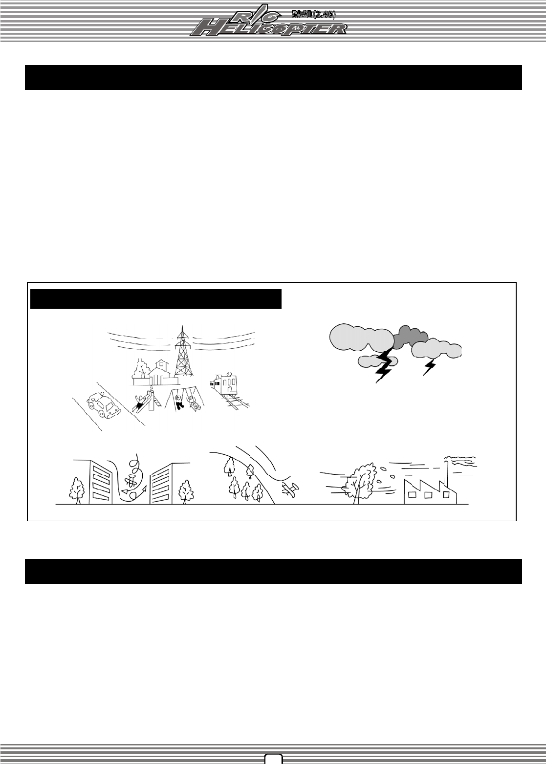
Don't fly helicopter at the places with these signs
Transmitter Features
The code pairing instruction for wk-2601:
A. Push the throttle stick to the lowest position and turn on the transmitter, and then the power indicator will flash ( Note: never move any
control sticks when it is flashing).
1. The usage of 2.4G technology is prompter in reaction, more sensitive in operation, and stronger in anti-interference.
2. The methods for automatic scanning, code pairing and ID allocation are shown as below :
B. The receiver LED will flash swiftly as soon as the battery is connected to the receiver, and will get a solid light 1-3 seconds later (Note: Do move
the right control stick when it is having a solid light). When the power indicator of the transmitter has stopped flashing to recover to the state of
power indication, the codes have been matched successfully, and you can fly the helicopter.
4
10. Charge jack. Charge the rechargeable battery pack at current 50mA, voltage ġ12V.
(Notice: the charge jack is forbidden to use for non-rechargeable battery pack).
The Factory Default Settings:
1
CHANNEL
2
3
4
5
ON/OFF
Rudder trim
6-CH Transmitter Features:
1. The DIP switches are available for various servos. It can perform the flight actions such as
ascending, descending, forward, backward, leftward, rightward and so on.
2. 4-channel micro-computer as the encoder; output power: ≤ 10mW; current drain: 50mA;
power source: 1.2V X 8 Ni-Cd battery ( 9.6V 600mAh) or 1.5V X 8 AA dry cell battery.
3. Free to switch between left-hand and right-hand throttles.
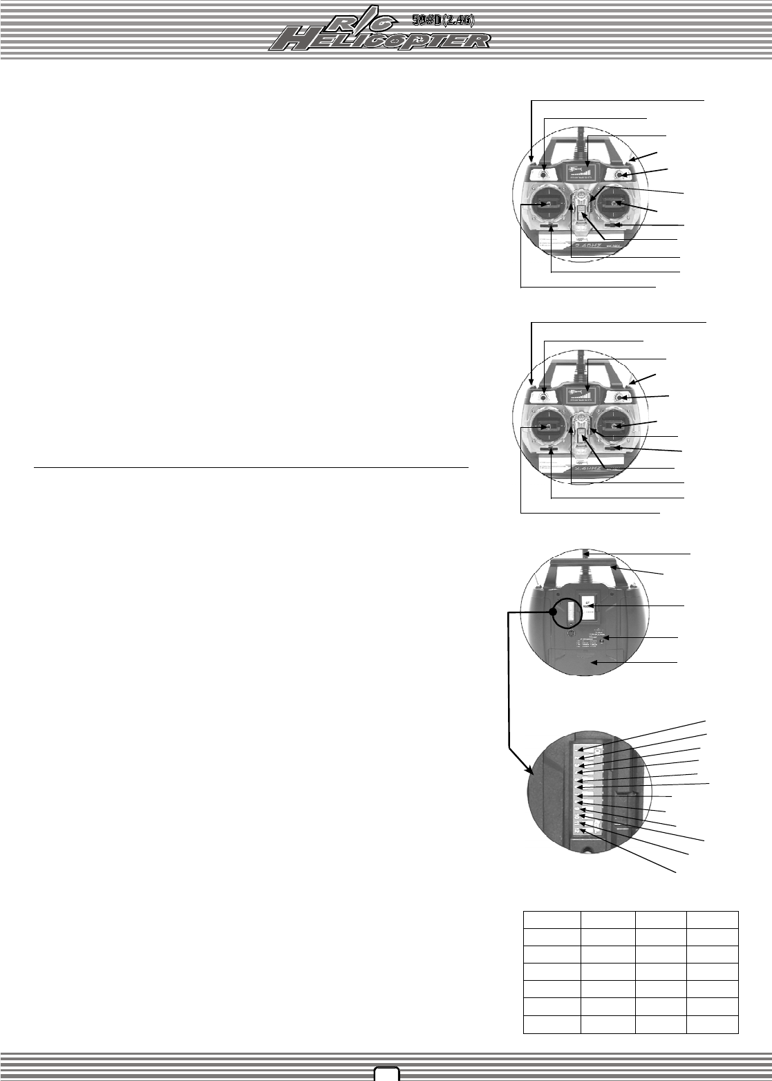
(MODE l - EUROPE & AUSTRALIA)
Power indicator
Throttle trim
Power switch
Right stick / Throttle
Aileron trim
Elevator trim
Left stick / Rudder
Power indicator
Throttle trim
Power switch
Right stick / Rudder
Aileron trim
Elevator trim
Rudder trim
Left stick /Throttle
(MODE lI - NORTH & AMERICA)
Fig. 1-1
Cover of the
battery box
Charge jack
Ornament
cover
Antenna
Fig. 2 DIP Switch ElEV
THRO
AILE
RUDD
11. Battery box. Please note the polarities while inserting the batteries.
9. Antenna. Transmit the signals.
Control Identification and function:
8. Power switch. Turn on or off the power of the transmitter. Push up the witch to turn on
the power, and push down to turn off.
3. Power indicator. The indicator is consisted of three colors: red, yellow, and green. Green
LED on means the electricity is enough to fly; Green LED off and yellow LED on indicate
the power is not enough and stop flying; Yellow LED off and red LED on show the power
is in extreme shortage, and please stop flying at once.
4. Elevator trim. It controls and modifies your helicopter forward and backward. Push up to
fly forward, and pull down to fly backward.
5. Rudder trim. The trim controls and modifies your helicopter leftward and rightward. Move
the trim left to fly leftward, and move right to fly rightward.
6. Throttle trim. The throttle trim controls your helicopter to ascend and descend. Push up
the trim to ascend, and pull down to descend.
7. Aileron trim. The aileron trim controls your helicopter leftward and rightward. Push the trim
left and fly left, and push the trim rightward and fly right.
1. Left stick / Rudder. It controls your helicopter forward, backward, left, and right. Push up
to fly your helicopter forward, pull down to fly backward, push leftward to fly left, and push
rightward to fly right.
2. Right stick / Throttle. It controls your helicopter ascending, descending, left moving
and right moving. Push up to ascend your helicopter; pull down to descend, push leftward
to move your helicopter left, and push rightward to move right.
1. Left stick / Throttle. It controls your helicopter ascending, descending, left, and right. Push up
to ascend your helicopter, pull down to descend, push leftward to fly left, and push rightward
to fly right.
2. Right stick / Rudder. It controls your helicopter forward, backward, left moving and right moving.
Push up to fly your helicopter forward, pull down to fly backward, push leftward to move your
helicopter left, and push rightward to move right.
MODE l - EUROPE & AUSTRALIA
MODE Il - NORTH AMERICA
OFF
OFF
OFF
6ON
7
CHANNEL
8
9
10
11
12
ON
OFF
OFF
ON
ON
OFF
ON/OFF
PIT
CCPM / NOR
PLT / PIT
RUDD MIX REV
CCPM / ELEV
13. Gear switch. Convert the gear switch to fold or release the skid landing system.
Switching the switch up is ON, and switching the switch down is OFF.
14. Flight mode switch: There are normal flight mode and 3D inversed mode. Put it on "N"
position is normal mode,and put it on "1" position is 3D inversed mode.
15. PIT limit / Exponential / Rudder mixing adjustment knob (V2).Under the help of
DIP switches, all the functions can be switchable.
12. Battery box cover. protect the transmitter battery. please open the box according to
the arrow direction when replace the battery.
16. Throttle curve / PIT curve / Gyro sensitivity adjustment (V1). IUnder the help of DIP
switches, the knob can experience throttle curve adjustment, PIT curve adjustment and
gyro sensitivity adjustment .
Gear
PIT limit / Exponential
/ Rudder mixing (V2)
Flight mode switch
Flight mode switch
Gear
Throttle curve /
PIT knob / Gyro
sens knob(V1)
OFF
OFF
Carrying handle
PIT limit / Exponential
/ Rudder mixing (V2)
Throttle curve /
PIT knob / Gyro
sens knob(V1)
RUDD MIX /
GYRO SENS
GEAR
EXP
5
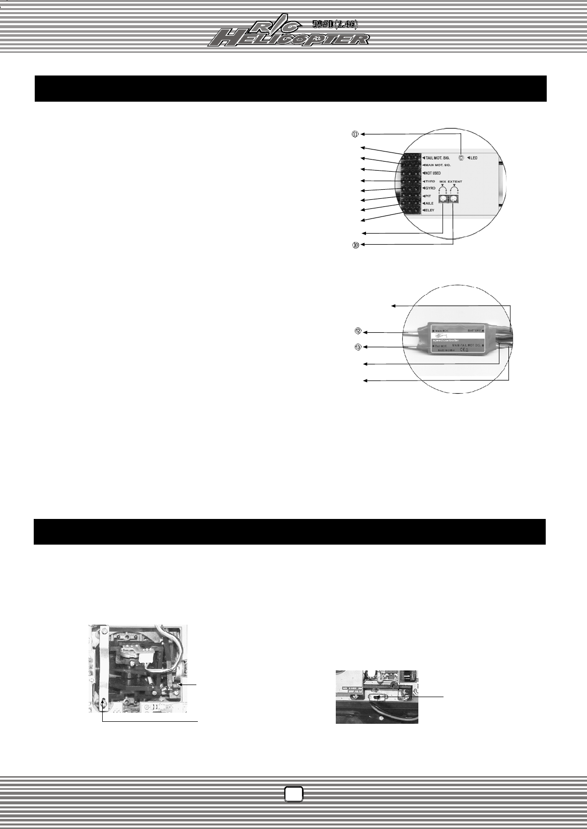
Receiver Identification (Fig. 3):
2. AILE. : Connect to the aileron servo.
1. ELEV. : Connect to the elevator servo.
13. Tail motor cable : Connect to the tail motor.
12. Main motor cable : Connect to the main motor.
14. Power cable : Connect to the battery.
11. LED. LED indicates the receiving status. Quick flash means the signal is
being received; LED on means the signal has been received; slow flash
means the signal fails to be received.
10. Servo extent adjustment (EXTENT) : EXTENT knob is used to set up
the servo travel. Clockwise adjustment increases the servo travel, and
counterclockwise adjustment decreases the servo travel.
Receiver Identification
Fig. 3
3. PIT. : Connect to the PIT servo.
4. RUDD. : Connect to the tail servo.
6. Not used.
Fig. 4
Fig. 4-1
Throttle DIP Switch (switching
to left end fits Modelƀ throttle
control; switching to right end fits
ModelƁ throttle control).
Remove the battery pack and the 4 fixing screws in the back cover of your WK-2601, and take off the back cover (Note: don't break the cables inside).
Unscrew the fixing screw of linkage using cross screwdriver and fix the linkage of another side using the screw. And then remove the throttle
arresting spring to fix in your expecting side. In this way, physical refit has been finished (Fig. 4).
Switch BetweenModel I and Model II
Throttle arresting pring
Fixing screw of linkage
ű
Ų
Ŭ
ŭ
Ů
ů
Ű
ų
Ŵ
Ų
MAIN MOT. SIG. (3 cables)
ų
TAIL MOT. SIG. (1 cable)
8. Tail motor signal cable : Connect to the tail motor signal cable.
7. Main motor signal cable : Connect to the main motor signal cable.
Power cable
5. THRO. :Connect to the speed controller
9. MIX : Please regulate according to the flight effects, clockwise adjustment
increases the mixing ratio control, counterclockwise decreases the mixing
ratio control.
FCC WARNING
This device complies with Part 15 of the FCC Rules. Operation is
subject to the following two conditions:
(1) this device may not cause harmful interference, and
(2) this device must accept any interference received, including interference that may cause
undesired operation.
NOTE: The manufacturer is not responsible for and radio or TV interference caused by
unauthorized modifications to this equipment. Such modifications could void the user’s authority
to operate the equipment.