Guard RFID Solutions PTE2 Generator for active RFID tag wakeup User Manual AtGuard System
Guard RFID Solutions Generator for active RFID tag wakeup AtGuard System
Contents
- 1. Install Guide
- 2. User Manual
Install Guide
07-00107-100
Guard RFID Solutions Inc. ©2017 All Rights Reserved 1
Installation Summary Guide
Proximity Tag Exciter
The following summary provides an overview of how to install
the Proximity Tag Exciter, and how to configure the installed
PTE within the Argus system. For more details regarding these
procedures, consult GuardRFID documents 07-00089-xxx,
Hardware Installation Guide, and 07-0032-xxx, Argus Software
Install and Configuration Guide, for more information.
Powering the Proximity Tag Exciter
When installing the PTE, be sure that all wiring is in conformance with local electrical codes
and ordinances.
The PTE can be powered using Power over Ethernet (PoE), or connected to a 12VDC central
power supply.
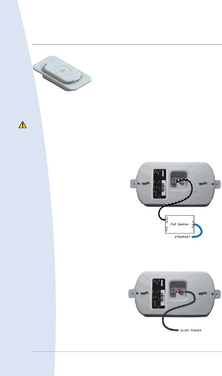
Connecting the PTE to PoE power
The PTE must have a dedicated Ethernet
cable and PoE Splitter that is not shared with
other devices.
Run an Ethernet cable from the network
switch to the intended location of the PTE.
Plug the cable into the PoE Splitter PoE In
port.
Plug the power patch cable into the PoE
Splitter 12VDC jack. Connect the other end
of the cable to the larger of the two
connectors on the back of the device—
connect the lead with the white stripe to the + terminal, and the other lead to the - terminal
(see diagram).
Record the serial number shown on the label on the bottom of the PTE. You will need this later
to configure the device.
Connecting the PTE to a central
+12VDC power supply
Each PTE must have a dedicated home run
power cable that is not shared with other
devices.
Run a 12VDC power cable from the power
supply to the intended location of the PTE.
07-00107-100 Proximity Tag Exciter Installation Summary
2 ©2017 All Rights Reserved Guard RFID Solutions Inc
Optionally add the split ferrite suppressor (API Delevan BF1835) to the power cable, ideally
less than 5” from the end of the cable.
Connect the cable to the larger of the two connectors on the back of the device—connect the
lead with the white stripe to the + terminal, and the other lead to the - terminal (see diagram).
Record the serial number shown on the label on the bottom of the PTE. You will need this later
to configure the device.
Mounting the Proximity Tag Exciter
Installing the Exciter at the correct location is critical to system operation. Be sure to mount
the PTE at the location designated in the deployment plan.
PTEs are designed to be flush mounted into drywall. To flush mount a PTE, cut a hole
roughly 105 x 175mm (4 1/8” x 6 7/8”) in the drywall and insert the device. Avoid studs—
the hole must be at least 35mm (1 3/8”) deep to accommodate the PTE, and that does not
include allowances for power cables or POE Splitters. The hole can be vertically or
horizontally oriented. Once it is inserted, use drywall screws to secure the PTE in place.
The PTE faceplate is cosmetic, and is designed to be attached after the PTE is flush
mounted. It can be removed, reattached, or discarded as needed.
The PTE can also be surface mounted using the two keyways on the back of the device.
Install two screws 213mm (8 3/8”) apart, then hand the PTE. You may wish to remove the
tabs on either end of the device for cosmetic reasons. The tabs are perforated, and can be
snapped off without tools.
If mounting the PTE to a ceiling or within a false ceiling, check your local regulations—your
region may have codes governing overhead installations.
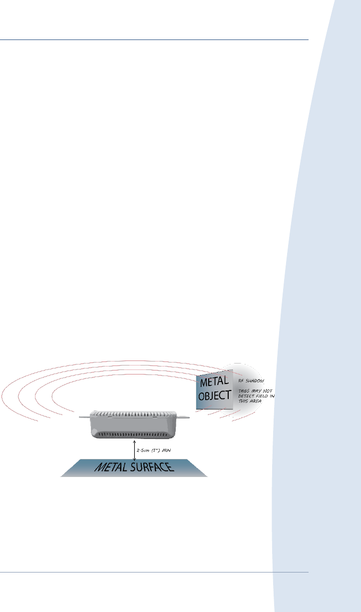
The PTE must be mounted at least 2.5cm (1”) from metal surfaces.
Metal adversely affects the Exciter’s low-frequency exciter field. Be sure that there is little
or no metal between the Exciter and the areas it is protecting, as it can reduce the exciter
field’s range and prevent tags from detecting it.
Proximity Tag Exciter Installation Summary 07-00107-100
Guard RFID Solutions Inc. ©2017 All Rights Reserved 3
Adding the Proximity Tag Exciter to Argus
Once powered and within range of an active Tag Reader, the PTE is automatically recognized
by Argus and can be incorporated into the deployment using the Configuration Manager.
Editing the PTE’s properties and settings
1. In the Configuration Manager objects pane, click the Nodes tab and expand the
Proximity Tag Exciters node. Locate the PTE in the list using its serial number.
2. Right-click the PTE and select Edit to open the Edit Proximity Tag Exciter window.
3. Use the Edit Proximity Tag Exciter window to edit the PTE’s properties and settings,
including its name and field size. Click Submit to confirm your changes.
Mapping the PTE’s location
Argus requires the Exciter’s precise location for system operation. You must place the PTE on
the map.
1. In the Configuration Manager objects pane, click the Locations tab and select the
floor/map where the PTE was installed.
2. Click the Nodes tab and expand the Proximity Tag Exciters node. Locate the PTE in the
list of Exciters using its serial number.
3. Drag and drop the PTE’s icon to its installed location on the floorplan, as per the
deployment’s “as built” drawings. Be as accurate as possible, and be absolutely sure to place
it on the correct map.
If you map the PTE to the wrong location, hold the Shift and Ctrl keys, then click
and drag the icon to a new location.
To remove the PTE from the floorplan, right-click its icon in the objects pane and
select Remove From Floor Plan.
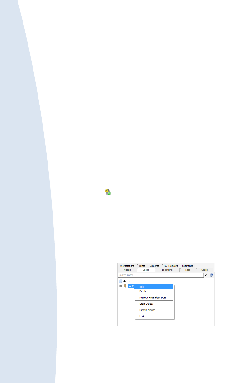
Incorporating the PTE into a gate
1. In the Configuration Manager
objects pane, click the Gate tab
and locate the gate that should
include the PTE.
2. Right-click the gate and select
Edit to open the Edit Gate
window.
3. In the Edit Gate window, select
the Tag Exciters tab.
4. Locate and select the PTE serial number in the Available Tag Exciters field, then click >.
Click Submit to confirm.

07-00107-100 Proximity Tag Exciter Installation Summary
4 ©2017 All Rights Reserved Guard RFID Solutions Inc
Additional Information
Guard RFID™ Solutions Inc.
Tele: 604.998.4018
Fax: 604.524.4018
guardRFID.com