HON HAI PRECISION IND T60H424 WLAN MiniPCI Type III User Manual 424 user manual
HON HAI Precision Ind. Co., Ltd. WLAN MiniPCI Type III 424 user manual
UserManual.wiki
>
HON HAI PRECISION IND
>
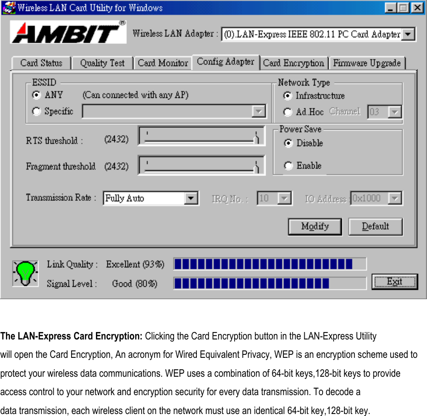
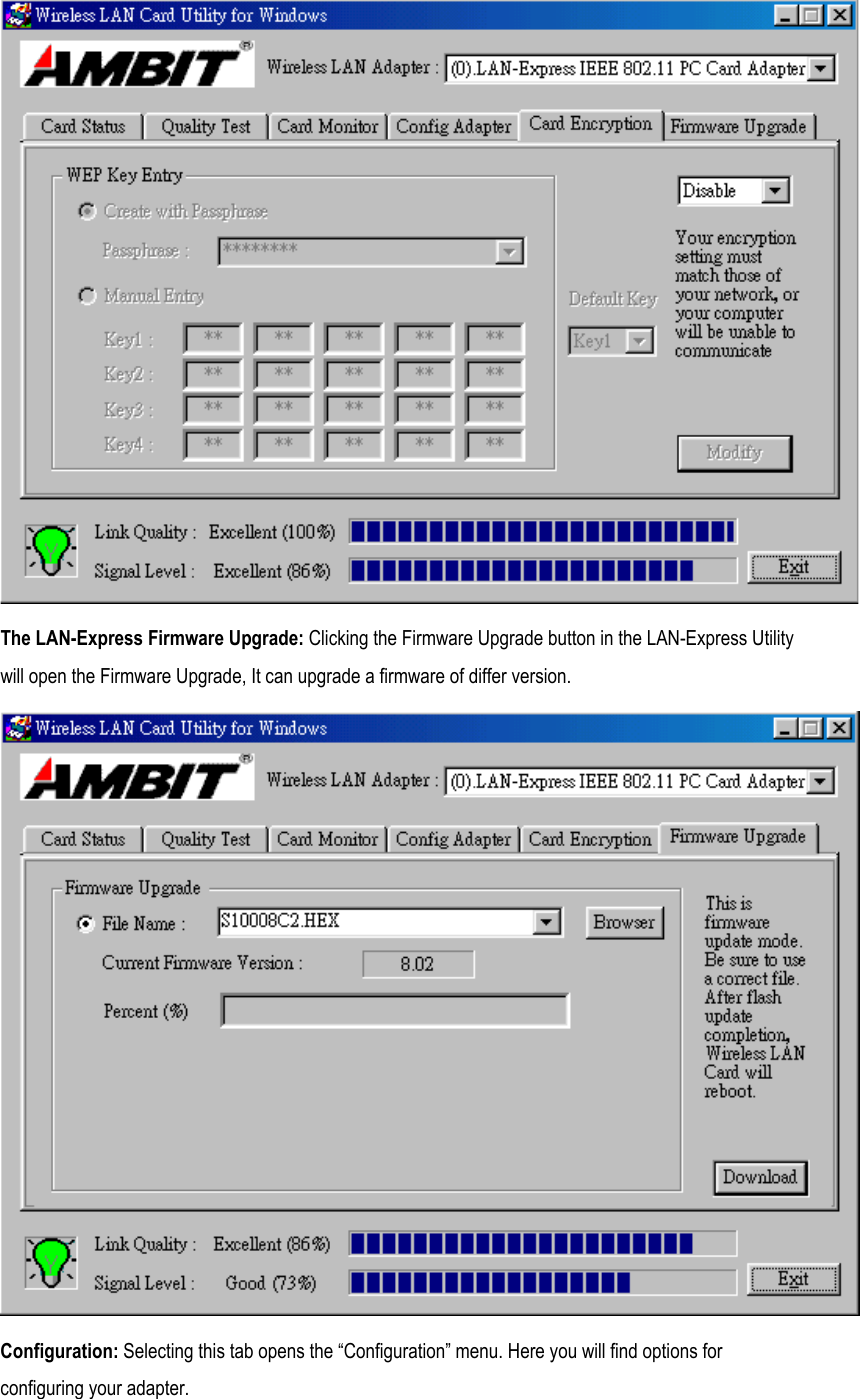
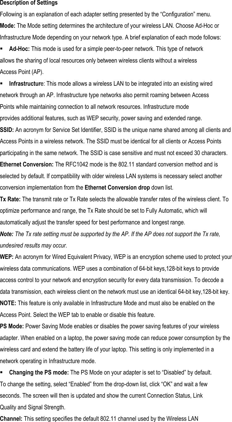
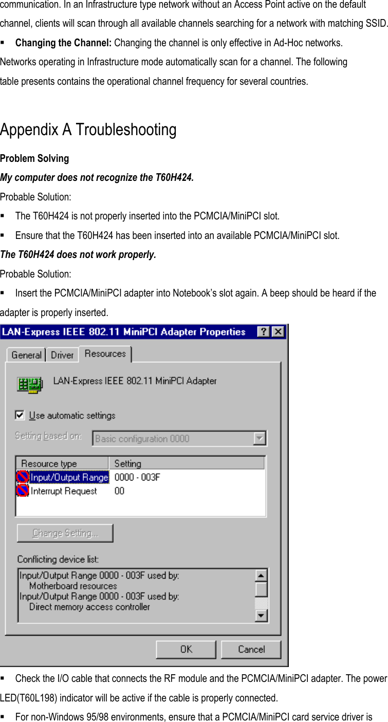
T60H424 User Manual
Manual
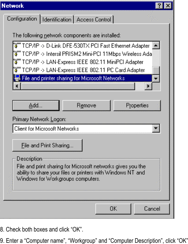
Navigation menu
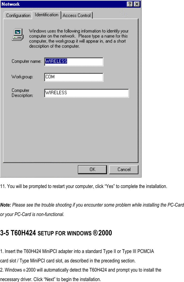
Upload a User Manual
Namespaces
Wiki Guide
HTML
PDF
Info
Views
User Manual
Discussion / Help
Navigation