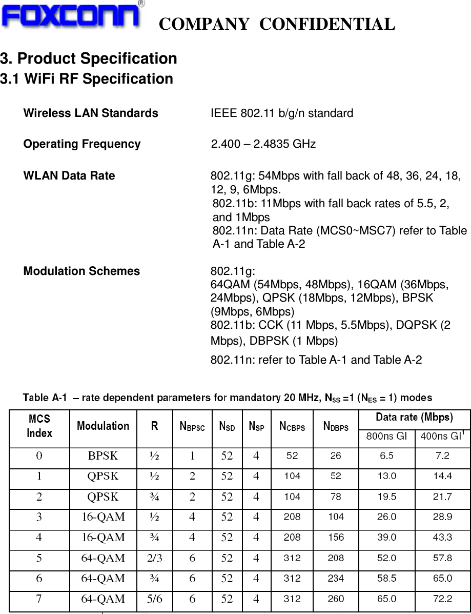
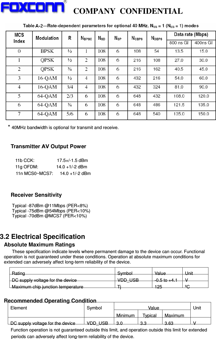
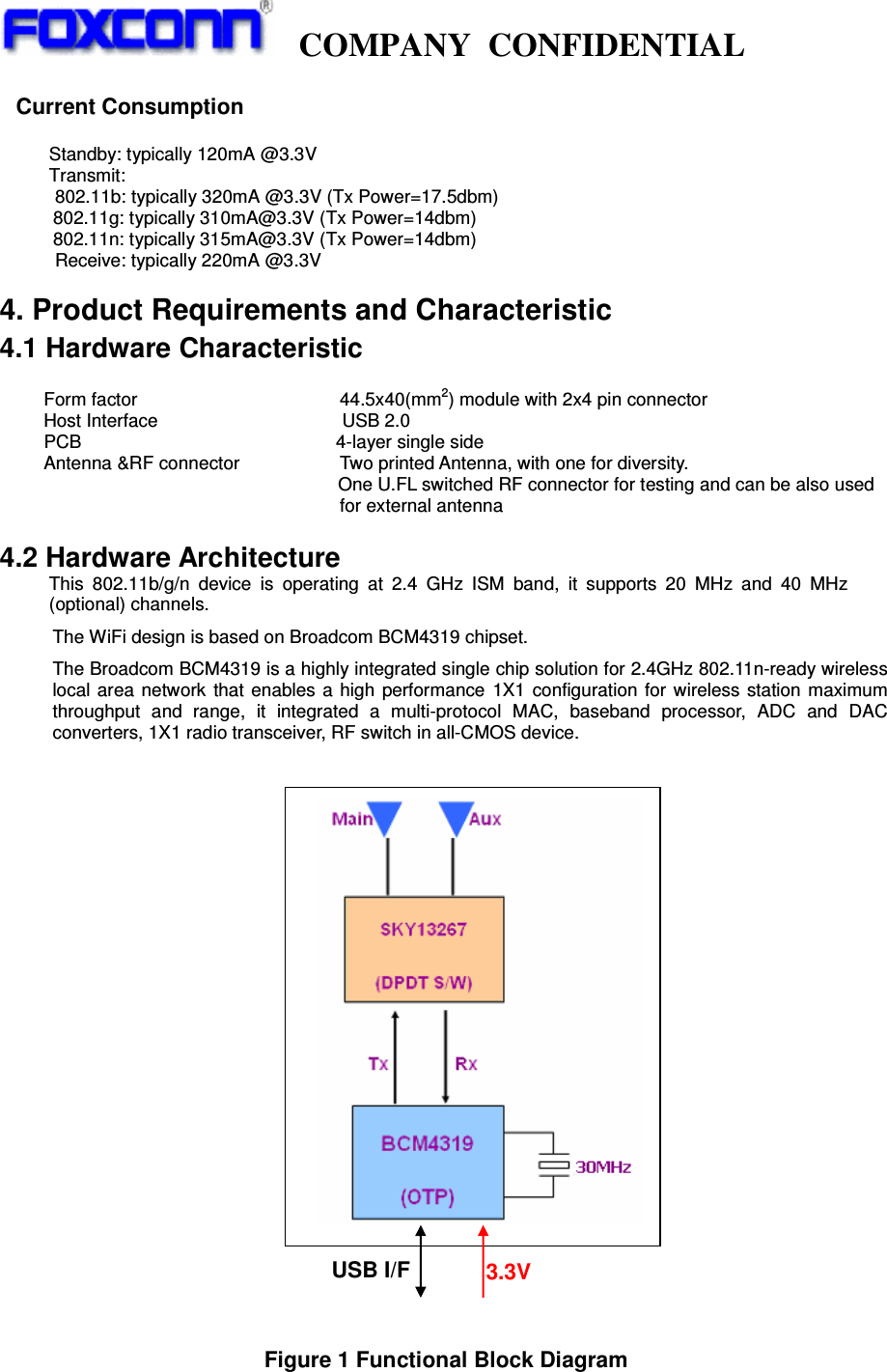
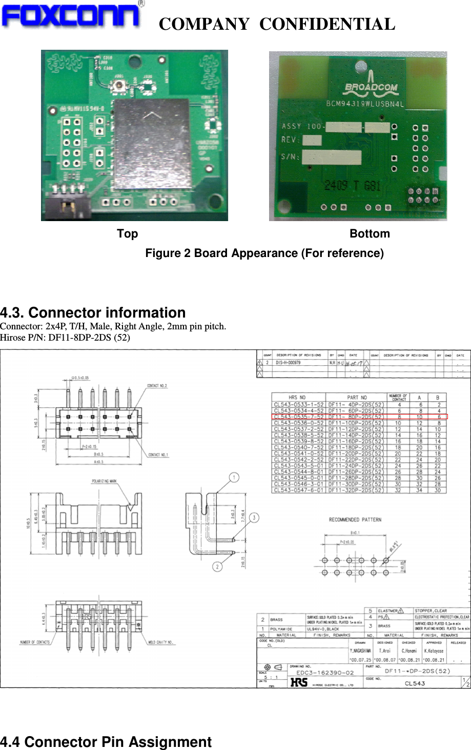
HON HAI PRECISION IND U98Z058 802.11b/g/n WLAN Module User Manual 20100719

HON HAI Precision Ind. Co., Ltd. 802.11b/g/n WLAN Module 20100719

User Manual

  COMPANY CONFIDENTIAL                        U98Z058.02 USB WiFi Module User Manual Rev. 1.0                Prepared by  Reviewed by  Approved by     Hans Dang      Gallon Tao                                  Index
  COMPANY CONFIDENTIAL             1. REVISION HISTORY...................................................................................................................................................3 2. INTRODUCTION ..........................................................................................................................................................4 3. PRODUCT SPECIFICATION .....................................................................................................................................5 4. PRODUCT REQUIREMENTS AND CHARACTERISTIC......................................................................................7 5. ANTENNA SPECIFICATION .....................................................................................................................................9 6. MECHANICAL DRAWING .......................................................................................................................................14 7. SCHEMATIC ...............................................................................................................................................................14 8. BOM LIST....................................................................................................................................................................16 9. PCB LAYOUT.............................................................................................................................................................17 10. PACKING ..................................................................................................................................................................22 11. REGULATORY.........................................................................................................................................................26 12. ENVIRONMENTAL REQUIREMENTS AND SPECIFICATIONS.....................................................................26
  COMPANY CONFIDENTIAL              1. Revision History   Date Change Note  REV Note 2010-06-17 Initial Release  1.0
  COMPANY CONFIDENTIAL             2. Introduction Project Name: 802.11 b/g/n wireless card  This documentation describes the product specification of the 802.11b/g/n WiFi Module. It is Compliant with IEEE Std 802.11b-1999, IEEE Std 802.11g-2003 and IEEE Std 802.11n-2009. It is a confidential document of Foxconn. 2.1 Scope This 802.11 b/g/n Module is available in the 2.4-GHz ISM band, it is compatible with the IEEE 802.11 b/g standard and the 802.11n standard. It allow user to switch to different vendors’ Access Points through the wireless networks and to prevent from eavesdropping. The 802.11 g data rate provides for 54, 48, 36, 24, 18, 12, 9, 6Mbps, 802.11b data rate provides for 11, 5.5, 2, 1 Mbps, it can also support 11n high data rate up to MCS7 with PHY data rate to 135Mbps.   2.2 Function   ¾  Single stream 802.11 support for both 20MHz and 40MHz (optional) channels provide PHY layer rates up to MCS7(150Mbps). ¾  Support IEEE 802.15.2 external 3-wire additional co-located wireless technologies such as Bluetooth, GPS, WiMax or UWB. ¾  Provides a small form factor solution and ultra low power consumption to support low cost requirement. ¾  Host interface supports USB, SDIO is not used in this product.
  COMPANY CONFIDENTIAL             3. Product Specification 3.1 WiFi RF Specification  Wireless LAN Standards       IEEE 802.11 b/g/n standard      Operating Frequency            2.400 – 2.4835 GHz  WLAN Data Rate      802.11g: 54Mbps with fall back of 48, 36, 24, 18, 12, 9, 6Mbps. 802.11b: 11Mbps with fall back rates of 5.5, 2, and 1Mbps 802.11n: Data Rate (MCS0~MSC7) refer to Table A-1 and Table A-2    Modulation Schemes            802.11g:  64QAM (54Mbps, 48Mbps), 16QAM (36Mbps,   24Mbps), QPSK (18Mbps, 12Mbps), BPSK (9Mbps, 6Mbps)   802.11b: CCK (11 Mbps, 5.5Mbps), DQPSK (2   Mbps), DBPSK (1 Mbps)                                     802.11n: refer to Table A-1 and Table A-2
  COMPANY CONFIDENTIAL                    * 40MHz bandwidth is optional for transmit and receive.  Transmitter AV Output Power                     11b CCK:          17.5+/-1.5 dBm      11g OFDM:        14.0 +1/-2 dBm        11n MCS0~MCS7:   14.0 +1/-2 dBm   Receiver Sensitivity  Typical -87dBm @11Mbps (PER<8%) Typical -75dBm @54Mbps (PER<10%) Typical -70dBm @MCS7 (PER<10%)       3.2 Electrical Specification Absolute Maximum Ratings    These specification indicate levels where permanent damage to the device can occur. Functional operation is not guaranteed under these conditions. Operation at absolute maximum conditions for extended can adversely affect long-term reliability of the device.  Recommended Operating Condition               Value Element Symbol Minimum  Typical  Maximum Unit DC supply voltage for the device  VDD_USB  3.0  3.3  3.63  V     Function operation is not guaranteed outside this limit, and operation outside this limit for extended      periods can adversely affect long-term reliability of the device.  Rating Symbol Value Unit DC supply voltage for the device VDD_USB -0.5 to +4.1 V Maximum chip junction temperature  Tj  125  ºC
  COMPANY CONFIDENTIAL             Current Consumption  Standby: typically 120mA @3.3V   Transmit:        802.11b: typically 320mA @3.3V (Tx Power=17.5dbm)     802.11g: typically 310mA@3.3V (Tx Power=14dbm)     802.11n: typically 315mA@3.3V (Tx Power=14dbm)       Receive: typically 220mA @3.3V 4. Product Requirements and Characteristic 4.1 Hardware Characteristic      Form factor                      44.5x40(mm2) module with 2x4 pin connector Host Interface                    USB 2.0    PCB               4-layer single side Antenna &RF connector  Two printed Antenna, with one for diversity.                                   One U.FL switched RF connector for testing and can be also used for external antenna  4.2 Hardware Architecture This 802.11b/g/n device is operating at 2.4 GHz ISM band, it supports 20 MHz and 40 MHz (optional) channels.   The WiFi design is based on Broadcom BCM4319 chipset. The Broadcom BCM4319 is a highly integrated single chip solution for 2.4GHz 802.11n-ready wireless local area network that enables a high performance 1X1 configuration for wireless station maximum throughput and range, it integrated a multi-protocol MAC, baseband processor, ADC and DAC converters, 1X1 radio transceiver, RF switch in all-CMOS device.                          Figure 1 Functional Block Diagram  USB I/F  3.3V
  COMPANY CONFIDENTIAL                                   Top                                    Bottom   Figure 2 Board Appearance (For reference)   4.3. Connector information Connector: 2x4P, T/H, Male, Right Angle, 2mm pin pitch. Hirose P/N: DF11-8DP-2DS (52)      4.4 Connector Pin Assignment
  COMPANY CONFIDENTIAL              Pin No.  Pin Name  Description  Pin No.  Pin Name  Description 1  VDD_USB  Power supply for the device, 3.3 typically. 2 VDD_USB Power supply for the device, 3.3 typically. 3 GND  Ground  4 GND Ground 5  USB_DP  USB differential positive  6  USB_DM  USB differential negative 7  WL_REG_ON  Enable/disable power the internal regulators 8 GND Ground  Notice:  WL_REG_ON is used by PMU to enable/disable power the internal regulators, ViH=1.6V, maximum=3.6V.   When WL_REG_ON is low (<1.2(1-20%)=0.96V) or the voltage at VDDIO is less than 0.96V, all six internal regulators are powered down. When WL_REG_ON is high (>1.6V) and the voltage at VDDIO is greater than 1. 6V, the CBUCK, LDO2p5V, CLDO, and LNLDO1 regulators are powered on default. The voltage at WL_REG_ON should not exceed 3.6V. There’s a 200Kȍ internal pull-down on WL_REG_ON. In normal operation mode, WL_REG_ON is pulled-high to 3.3V; and when the device is not needed in the system, WL_REG_ON should be driven low while VDDIO remains powered, which is called Low-Power shutdown mode.    5. Antenna Specification            The antennas are PCB printed antenna, its pattern show as below.
  COMPANY CONFIDENTIAL             Features  2.4 to 2.5 GHz operation VSWR better than 2:1 Efficiency >72%                      Ant A Ant B
  COMPANY CONFIDENTIAL              Phi 0 plane cut ant A  Phi 90 plane cut ant A
  COMPANY CONFIDENTIAL              Theta 90 plane cut ant A  Phi 0 plane cut ant B
  COMPANY CONFIDENTIAL              Phi 90 plane cut ant B  Theta 90 plane cut ant B
  COMPANY CONFIDENTIAL             6. Mechanical Drawing   7. Schematic
  COMPANY CONFIDENTIAL
  COMPANY CONFIDENTIAL              8. BOM List
  COMPANY CONFIDENTIAL               9. PCB Layout  U98Z058.02 PCB is a 4-layer, HDI design, its surface finish is Immersion Silver.  Stack-up
  COMPANY CONFIDENTIAL              Top Layer   Layer 2
  COMPANY CONFIDENTIAL              Layer 3   Bottom Layer
  COMPANY CONFIDENTIAL              Top Side Solder Mask   Top Side Silk Screen
  COMPANY CONFIDENTIAL              Top Side Paste Mask   Bottom Side Solder Mask
  COMPANY CONFIDENTIAL             10. Packing  10.1 Label  10.1.1. MAC ID label: P/N:503.00653.005……1 MAC ID/product   Human readable: A.MAC ID:XXXXXXXXXXXX MAC ID Barcode, follow Foxconn standard. C.P/N:U98Z058.02 D.MO: MO-VVSS a. First MO: is letter b. Second MO is Foxconn MO, follow Foxconn standard c. VV: The engineering version d. SS: The version of A300/A400 product   Barcode content: XXXXXXXXXXXX MAC ID Barcode, follow Foxconn standard Barcode type: code39, height: 4mm   10.1.2. Carton label: P/N:503.00098.005
  COMPANY CONFIDENTIAL               A.XXXXXXXX: the Foxconn MO B. Qty: XXX XX: The quantity of product in carton Barcode content: The quantity of product in carton C.REV: VVSS VV: The engineering version   SS: The version of A300/A400    D.CIPPYWWXXXX Carton ID Text Definition: C - Carton l - Production Location Code PP - Production Line Identity Y-year code: 2010 AD WW - The products are built in the 14th week XXXX - The four decade serial numbers
  COMPANY CONFIDENTIAL             10.1.3 Pallet label: P/N:503.00089.005    Pallet ID Text Definition˖ PIPPYWWXXXX P - Pallet l - Production Location Code PP - Production Line Identity Y-year code: 2010 AD WW - The products are built in the 14th week XXXX - The four decade serial numbers
  COMPANY CONFIDENTIAL             10.2 Assembly Drawing & Packing Standard   Federal Communication Commission Interference Statement This equipment has been tested and found to comply with the limits for a Class B digital device, pursuant to Part 15 of the FCC Rules.  These limits are designed to provide reasonable protection against harmful interference in a residential installation.  This equipment generates, uses and can radiate radio frequency energy and, if not installed and used in accordance with the instructions, may cause harmful interference to radio communications.  However, there is no guarantee that interference will not occur in a particular installation.  If this equipment does cause harmful interference to radio or television reception, which can be determined by turning the equipment off and on, the user is encouraged to try to correct the interference by one of the following measures:  - Reorient or relocate the receiving antenna. - Increase the separation between the equipment and receiver. - Connect the equipment into an outlet on a circuit different from that to which the receiver is connected. - Consult the dealer or an experienced radio/TV technician for help.  This device complies with Part 15 of the FCC Rules. Operation is subject to the following two conditions: (1) This device may not cause harmful interference, and (2) this device must accept any interference received, including interference that may cause undesired operation.  FCC Caution: Any changes or modifications not expressly approved by the party responsible for compliance could void the user's authority to operate this equipment.  IMPORTANT NOTE: FCC Radiation Exposure Statement: This equipment complies with FCC radiation exposure limits set forth for an uncontrolled environment. This equipment should be installed and operated with minimum distance 20cm between the radiator & your body. This transmitter must not be co-located or operating in conjunction with any other antenna or transmitter.  IEEE 802.11b or 802.11g operation of this product in the U.S.A. is firmware-limited to channels 1 through 11. This device is intended only for OEM integrators under the following conditions: 1) The antenna must be installed such that 20 cm is maintained between the antenna and users, and  2) The transmitter module may not be co-located with any other transmitter or antenna,  3) For all products market in US, OEM has to limit the operation channels in CH1 to CH11 for 2.4G band by supplied firmware programming tool. OEM shall not supply any tool or info to the end-user regarding to Regulatory Domain change. As long as 3 conditions above are met, further transmitter test will not be required. However, the OEM integrator is still responsible for testing their end-product for any additional compliance requirements required with this module installed (for example, digital device emissions, PC peripheral requirements, etc.). IMPORTANT NOTE: In the event that these conditions can not be met (for example certain laptop configurations or co-location with another transmitter), then the FCC authorization is no longer considered valid and the FCC ID can not be used on the final product. In these circumstances, the OEM integrator will be responsible for re-evaluating the end product (including the transmitter) and obtaining a separate FCC authorization. End Product Labeling This transmitter module is authorized only for use in device where the antenna may be installed such that 20 cm may be maintained between the antenna and users. The final end product must be labeled in a visible area with the following: “Contains FCC ID: MCLU98Z058”. Manual Information To the End User The OEM integrator has to be aware not to provide information to the end user regarding how to install or remove this RF module in the user's manual of the end product which integrates this module. The end user manual shall include all required regulatory information/warning as show in this manual.
  COMPANY CONFIDENTIAL               11. Regulatory  TBD  12. Environmental Requirements and Specifications  12.1 Temperature  12.1.1 Operating Temperature Conditions  The product shall be capable of continuous reliable operation when operating in ambient temperature of 0  to +ć70 .ć  12.1.2 Non-Operating Temperature Conditions Neither subassemblies shall be damaged nor shall the operational performance be degraded when restored to the operating temperature when exposed to storage temperature in the range of -10  to +ć85ć.  12.2 Humidity  12.2.1 Operating Humidity Conditions  The product shall be capable of continuous reliable operation when Industry Canada Statement This device complies with RSS-210 of the Industry Canada Rules. Operation is subject to the following two conditions: 1) this device may not cause interference and 2) this device must accept any interference, including interference that may cause undesired operation of the device  IMPORTANT NOTE: IC Radiation Exposure Statement: This equipment complies with IC radiation exposure limits set forth for an uncontrolled environment. This equipment should be installed and operated with minimum distance 20cm between the radiator & your body.  This device is intended only for OEM integrators  under the following conditions: 2/!The antenna must be installed such that 20 cm is maintained between the antenna and users, and  3/!The transmitter module may not be co-located with any other transmitter or antenna,  4/!For all products market in CANADA, OEM has to limit the operation channels in CH1 to CH11 for 2.4GHz band by supplied firmware programming tool. OEM shall not supply any tool or info to the end-user regarding to Regulatory Domain change. As long as 3 conditions above are met, further transmitter test will not be required. However, the OEM integrator is still responsible for testing their end-product for any additional compliance requirements required with this module installed (for example, digital device emissions, PC peripheral requirements, etc.).  IMPORTANT NOTE: In the event that these conditions can not be met (for example certain laptop configurations or co-location with another transmitter), then the IC authorization is no longer considered valid and the IC ID can not be used on the final product. In these circumstances, the OEM integrator will be responsible for re-evaluating the end product (including the transmitter) and obtaining a separate IC authorization.  End Product Labeling The final end product must be labeled in a visible area with the following: “Contains TX IC : 2878D-U98Z058”. Manual Information That Must be Included The OEM integrator has to be aware not to provide information to the end user regarding how to install or remove this RF module in the user's manual of the end product which integrates this module. The end user manual shall include all required regulatory information/warning as show in this manual.
  COMPANY CONFIDENTIAL             subjected to relative humidity in the range of 10% and 90% non-condensing.  12.2.2 Non-Operating Humidity conditions  The product shall not be damaged nor shall the performance be degraded after exposure to relative humidity ranging from 5% to 95% non-condensing.

Navigation menu