HUAC F27-5S Wireless Cellular Repeater User Manual
SHENZHEN HUAPTEC CO., LTD Wireless Cellular Repeater
HUAC >
User Manual
1
(F27/F23/F20-5S )

2
Table of content ................................................................................................................. 2
How it works ....................................................................................................................... 3
Package contents .............................................................................................................. 3
Features .............................................................................................................................. 5
Booster’s port description ................................................................................................. 5
LCD Introduce .................................................................................................................... 6
Manual gain control (MGC) ............................................................................................ 6
Install Hiboost Booster system ......................................................................................... 6
Before you install ........................................................................................................ 6
Installation overview.................................................................................................. 7
1. Install Outdoor Antenna ................................................................................. 8
2. Install Indoor Antenna .................................................................................. 10
3. Install the signal booster .............................................................................. 11
4. Booster Commissioning ................................................................................ 11
Trouble Shooting .............................................................................................................. 15
FCC RF Exposure Statement .......................................................................................... 15
Notice ................................................................................................................................ 15
Specifications ................................................................................................................... 16
3
F27/F23/F20-5S are designed to help mobile users amplify weak signals of 2G, 3G
and 4G. They are bi-directional amplifiers.
The donor antenna receives the signals from the cell tower, amplifies it, and
transmits to the signal booster. Then the indoor antenna will receive the signal and
retransmit it to your mobile device.
The signals produced by your phone are also amplified by the indoor antenna via
the booster and donor antenna.
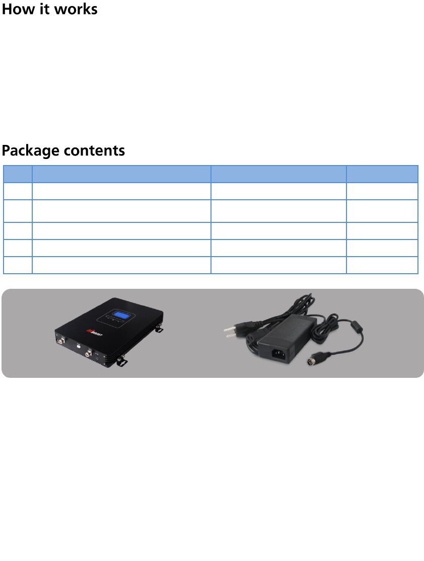
No.
Name
Description
Quantity
1
Hiboost Industrial Booster
1
2
Adapter
12V/7A
1
3
Plastic Expansion bolt
Φ8
5
4
Tapping Screw
M6*50
4
5
User Manual
1
F27/F23/F20-5S booster Power supply12V/7A
*Outdoor and indoor antennas and cables are required for installation
(purchased separately).
F27/F23/F20-5S Industrial boosters cannot transmit signals without an outside and
inside antenna connected by a cable. F27/F23/F20-5S can install up to 15 indoor
antennas, usually, we recommend install up to 8~10 indoor antennas. The detail
number of antennas, length of cable or other accessories needed can vary
according to the size and make of the structure, lack of signal strength, or where
the structure resides. Or you can contact us or our reseller to find out what you
need.
Multiple antenna installation Sample
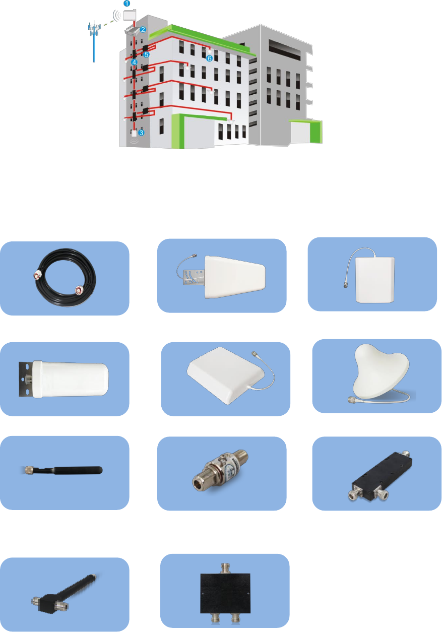
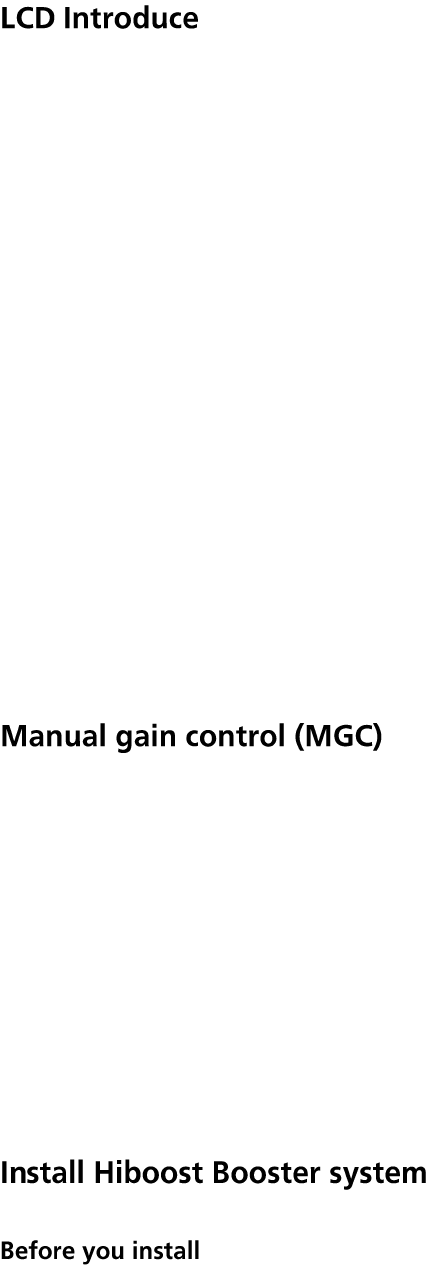
4
1.Outdoor Antenna 2. Booster 3.Indoor Panel Antenna
4. Coupler 5. Splitter 6. Omni ceiling antenna
Optional antenna kits Recommended
Outdoor ceiling mount dome antenna
Wide Band Yagi antenna
Indoor panel antenna
Omni ceiling antenna
Indoor panel antenna
Whip antenna
Lightening protector
Cavity Splitter (2,3,4 way)
RF cables (3D,5D,8D)
Coupler
Wilkinson Splitter (2,3,4 way)
5
Embedded CPU, self-adaptive intelligent system to make booster system very
easy to install and better performance is guaranteed under complex and
constantly changing RF environment.
ISO: Intelligent isolation processing to avoid self-oscillation, quite wide
adjusting range to stabilize the signal strength/quality for clearer voice/ higher
data speed and avoid interference to mobile network
ALC: Intelligent ALC, quite wide adjusting range to improve the signal quality
for clearer voice and higher data speed
LCD Display: to display ISO status, ALC status, actual gain and downlink
output power that make booster installation and troubleshooting much easier
MGC: control button to adjust the gain for both uplink and downlink
independently, 31dB range
Excellent RF performance, larger coverage area, clearer voice and higher
speed data services.
Elegant design, small size, very low power consumption to save cost during
operation and low heat dissipation.
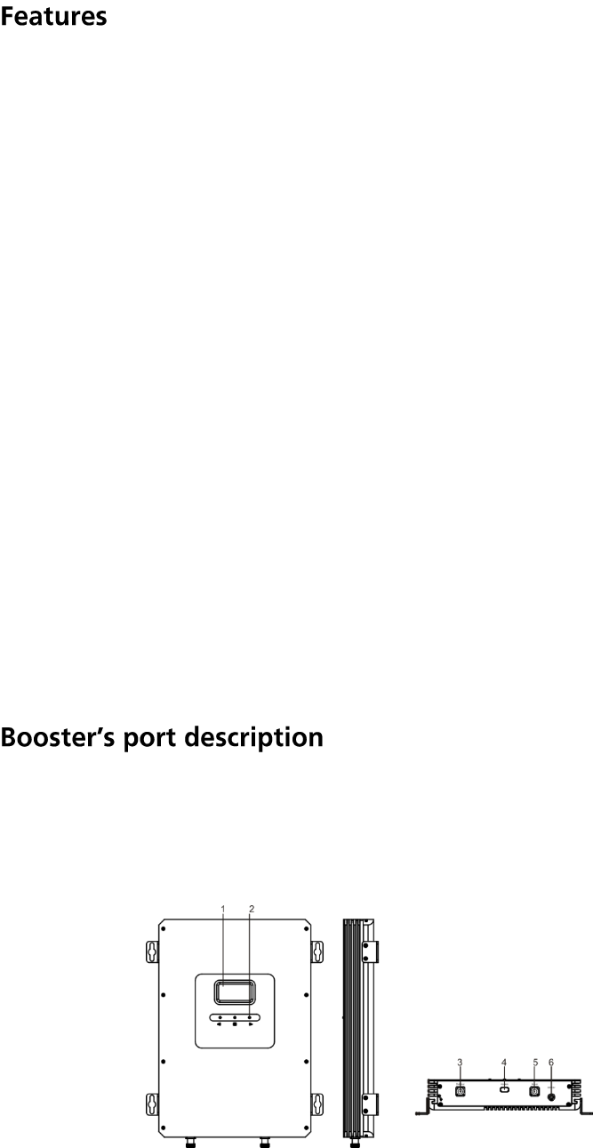
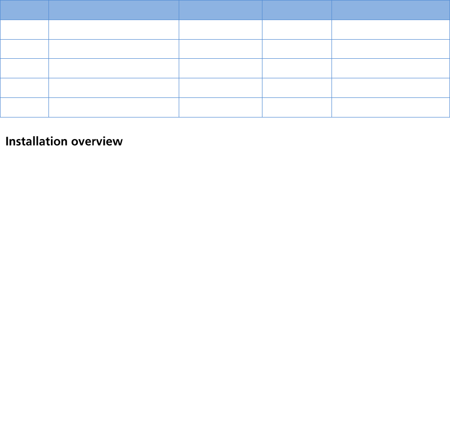
The following image shows the key components of the booster. There are 3 parts:
first part is LCD indicator, which will show the booster status. Second part is control
button. Third part is connectors to the outdoor antenna and indoor antenna. The
following tables and graphs show the details.
1. LCD 2. Control Button 3. Outdoor antenna port
4. Debug Port 5. Indoor antenna port 6. Power connector
6
After power on the repeater, the display area of working frequency will light all the
time, the working frequency will display in turn.
“ISO” Isolation alarm indication.
When the repeater doesn’t have enough isolation between the outdoor and
indoor antennas, the “ISO” is flashing. Vice Versa, the “ISO” is off.
”AlC” Strong receiving power alarm indication.
When the repeater’s receiving too strong signal from outside, output power gets
overrated and “AlC” starts flashing. When output power is balanced, the “AlC” is
off.
Gain or Power indication.
The displayed value represents the real-time gain and power.
When the repeater’s output power is lower than -10dBm, the LCD will display “---”.
When LCD screen is in the ”OFF” state and the repeater breaks down, LCD screen
will be flashing.
When LCD screen is ”ON” and the repeater breaks down, LCD6 and LCD7 will
display ”OFF” under the current band.
Since the booster has intelligent software system, MGC attenuation is not needed,
except for the cases when you don't feel comfortable about ISO or ALC flashing, or
in some extreme cases you might need to attenuate gain value.
When the LCD is in the circulation display or page turning query mode, press the
key into the setting mode and choose operation objects: frequency, uplink or
downlink gain .
Note:
In case you need to adjust gain, please ensure uplink gain to be equal with or to
be 5dB less than downlink gain, uplink gain shouldn’t be more than downlink gain
in order to avoid interference with mobile network.
• Make sure you have sufficient cable length between proposed outdoor/indoor
antennas.
7
• Make sure the place where you install the booster is near to one existing
electrical outlet. It should also be well ventilated, away from excessive heat,
moisture, and direct sunlight.
Install tools and accessories:
No.
Name
Specification
Quantity
Remark
1
Plastic expansion bolt
Φ8
5
Standard accessories
2
Tapping screw
M6*50
4
Standard accessories
3
Hanging folder
1
Standard accessories
4
Reciprocating drill
1
Engineering-owned
5
Shot bit
Ø8
1
Engineering-owned
The booster has LCD display and intelligent self-adaptive system, LCD displays
real time working state, and intelligent self-adaptive system can automatically
calculate and adjust the booster to obtain its best performance, so it is very easy
to install for end-user.
General installation steps:
Step1. Install your outdoor antenna on the roof where there is the strongest signal.
Step2. Install the indoor antenna where you want to improve the signal.
Step3. Mount your signal booster, connect the cables to the signal booster from the
outdoor antenna and indoor antenna at the designated ports, and connect the
booster to the AC supply (make sure all the cables are connected).
Step4. Plug in the booster to a power supply and self-adaptive system will
automatically adjust best performance in 30 seconds. (NB! Before you plug it in,
make sure all the cables are connected firmly!). For more details refer to “Booster
Commissioning”.
8
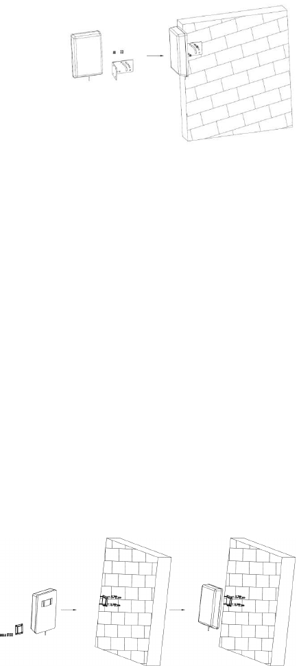
1. Outdoor Antenna 2. Booster 3. Indoor Antenna
1. Install Outdoor Antenna
1.1 How to find the position with the strongest receiving signal
The booster’s main function is to improve weak RF signal inside a house, office or
any other indoor area. The receiving strength of the outdoor antenna and the
strength of the signal reception outdoors directly affect the efficiency of indoor
coverage. That’s why it’s crucially important to install the outdoor antenna in the
point where signal reception is the strongest.
There are two methods to find the strongest receiving signal. One is to use
booster’s LCD display, the other is to use mobile phone to test signal bars. We’d
highly recommend you to use LCD display as this method is more accurate.
LCD Display Method
Connect the outdoor antenna to the booster’s outdoor port with an original coaxial
cable that comes in a kit and power on the booster. Fix the outdoor antenna
outside the window or on the top of the building and point it to the nearest cell
tower. Then have a look at output power value displayed on LCD.
The outdoor antenna receives the strongest signal when the booster’s output
power reaches its full value. The place where you can reach it is the best to mount
the outdoor antenna.
9
Remark: when ALC shows up flashing, it means the receiving signal power is
stronger than the system needs it. It is recommended to adjust outdoor antenna
position unless ALC alarm disappears. Or you can leave it as it is to let the booster
self-adjust automatically. However when ALC flashes, and the displayed gain is
more than 30 dB less than rated gain value, try to adjust outdoor antenna to
decrease the receiving power.
Mobile Phone Method
You can use telephone to test signal strength near the window or on the top of the
building. The number of bars on network indicator will define approximate
strength of the received signal. Normally the roof of the building is the best place
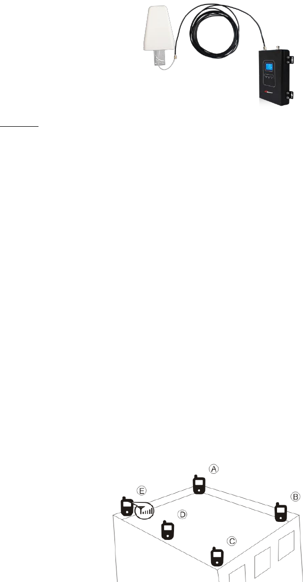
to receive the strongest signal. As shown on the graph below, you need to test the
signal in points from A to E, and select a place with best signal strength for outdoor
installation. It is recommended to use mobile app that can display signal level,
since it is more accurate than checking signal bars.
More tips: Please try to pick up signal from cell towers that are not so busy, which
can be estimated by the population density in the area served by this tower. It’s
also recommended to avoid a cell tower near a supermarket, shopping mall,
stadium and any other public place visited by many people regularly. This will
10
help on successful phone call connections or higher speed data services.
1.2 Install Outdoor Antenna
In most cases, the panel antenna is the best choice. You can also choose wide
band YAGI antenna as an option.
There are 2 types of installation: wall mount or pole mount.
Install outdoor panel antenna onto the wall for your reference:
Step1: Unscrew antenna from L-mounting bracket on antenna base with wrench.
Step2: Mount vertical plate of the L-bracket on the wall with supplied screws.
Step3: Screw antenna back onto horizontal plate.
Notes:
• Wrap waterproof tape around the connectors between outdoor antenna and
feeder line to avoid water or other kinds of damage.
2. Install Indoor Antenna
According to the requirement of practical application, please select Indoor panel
antenna, or Omni-ceiling antenna as indoor antenna for coverage
Install indoor panel as reference.
Step1: Select a place on a wall projecting the area where you want reception.
Normally, to provide an overall coverage, you will need to choose a corner.
Step2: Mount the bracket on the wall after drilling the screw to the wall.
Step3: Put the panel antenna on the bracket.
11
When you choose Indoor ceiling omni antenna or whip antenna, the best place to
install it is the center of your house as the graph shows.
3. Install the signal booster
Step1: Select an indoor location near to a power outlet on a wall.
Step2: Mount the booster with the screws included as shown in the figure.
Step3: Connect the outdoor antenna cables to booster connector marked
“outdoor”. Tighten the connection with hand or wrench.
Step4: Connect the indoor antenna cables to booster connector marked “indoor”.
Tighten the connection with hand or wrench.
Step5: Connect the AC power cord to the signal booster, and then connect the
plug to the electrical outlet to power on the booster
Booster installation Connection from cable to booster
4. Booster Commissioning
Overview: The booster has quite intelligent startup system, booster commissioning
is an automatic process to guarantee its optimal performance.
After finishing the booster system installation, please power on the booster, the
booster starts its initialization to check it is receiving signal, the isolation status to
ensure its best performance. This will take around 3~5 seconds.
After the booster start up, please check whether the coverage is good. If it is good,
12
the booster system is completed.
You can check the output power displayed in LCD. It may vary at 1~3dB difference
which is normal due to outdoor signal conditions. It would be perfect that the
output power reaches its rated one for largest coverage; but you can always
leave it even though it doesn't as long as the coverage is good enough for you.
In case the coverage is not enough, please take below measures as per below
conditions.
1. The rated output power is reached, but the coverage is not enough or the
signal in specific areas has not been improved
Check whether the indoor antenna is installed correctly or not, you may try to
move the antenna location to improve coverage.
Check if it is necessary to adjust the direction of the indoor antenna.
Check whether it is necessary to add more indoor antennas since barriers
block the signal penetration.
2. The rated output power is not reached.
1) Please adjust the outdoor antenna to get a stronger receiving signal in
order to get higher output power (not necessarily to reach rated value as long
as the coverage is enough)
2) please observe the LCD display, if the reading gain is less than rated value
and "ISO" is flashing, it means the gain is reduced by ISO function for not
having enough isolation.
Measures: One of below actions are recommended to eliminate ISO
problems and increase the gain
Adjust the antenna’s directions or locations, or enlarge the distance between
them.
Enlarge the vertical or horizontal distance between donor antenna and server
antenna.
Use the barrier, such as walls, to increase the isolation.
Change server antenna(server antenna can be changed to other antenna
type which has better directional antenna pattern, also you can let server

13
antenna and donor antenna point opposite direction).
Reduce the booster’s downlink gain by the control button. Keep the uplink
attenuation value and downlink attenuation value same then restart the
booster.
More about "ISO" indication
ISO status indicates if the booster has enough isolation between outdoor and
indoor antennas in order to avoid loop back or so-called self-oscillation. This is
an intelligent system that works automatically to ensure the booster has no
interference to either call/data services, or mobile networks. "ISO" flashes in
LCD display when ISO function works; the flashing status shows ISO is working,
and the self-oscillation has been eliminated.
LED
Status
Meaning
Solve methods
ISO
status
Remain still
No loop back or
no self-oscillation
NO action is needed
Flashing but actual gain
is not more than 30dB less
than rated gain
Slight loop back
or self-oscillation
NO action is needed
Flashing but actual gain
is more than 30dB less
than rated gain
Deep loop back
or self-oscillation
Working properly, but deep loop,
below actions are recommended:
Adjust the antennas’ directions or
locations to enlarge the distance.
Add the vertical or horizontal
distance between outdoor and
indoor antennas.
Use the barrier like walls to
increase the isolation.
Reduce the booster’s gain by
external attenuator or replace
with lower gain antenna if the
above methods don’t work.
More about "AGC" indication: Flashing ALC indicates if the booster has a
strong receiving power
LED
Status
Meaning
Solve methods
ALC
status
Remain still
Output power is
not weak or just
suitable
Check coverage, leave it if it is good;
take below actions to increase signal if
coverage is not good.
1. Adjust the antenna direction or
location to get stronger receiving
signal
2. Replace current antenna with higher

14
gain to get stronger receiving signal
Flashing but actual gain
is not more than 30dB
less than rated gain
Full output power
Working properly
Flashing but actual gain
is more than 30dB less
than rated gain
Too strong
receiving signal
Working properly, but too strong signal,
actions are recommended:
1. Adjust the antennas’ directions or
locations to lower down input power.
2. Reduce the booster’s gain by
external attenuator or replace with
lower gain antenna if the above
methods don’t work.
Notes: The flashing ISO and ALC status are to show you that ISO and ALC functions
are working to solve the self-oscillation or strong signal problems, so the problems
have been solved already. In most cases, there is no need for you to do anything,
except deep self-oscillation or too strong signals that we recommend your actions
but not mandatory, since the booster still solves the problems. However it is
already more proper for you to deal with it.
More about LCD indication:
LCD
Status
Meaning
Solve methods
“---” status
Output power is
lower than
-10dBm
Check coverage, leave it if it is good;
take below actions to increase signal
if coverage is not good.
1. Adjust the antenna direction or
location to get stronger receiving
signal
2. Replace current antenna with
higher gain to get stronger receiving
signal
“OFF”
status
Actual gain is
more than 51dB
less than rated
gain
Severe loop back
or self-oscillation
or output power
is severe over
rated to lead that
the repeater
breaks down.
Not working properly, actions must
be taken and recommend the below
actions:
1. Adjust the antennas’ directions or
locations to lower down input
power or enlarge the distance.
2. Add the vertical or horizontal
distance between outdoor and
indoor antennas.
15
Flashing
LCD
screen
3. Use the barrier like walls to
increase the isolation.
4. Reduce the booster’s gain by
external attenuator or replace
with lower gain antenna if the
above methods don’t work.
Problem
Resolution
The signal booster has no power.
Check that the AC outlet is working.
The booster’s power is on but the phone is
not connected into the network and still
cannot communicate.
Try to fasten the connections between the
different parts of the system.
Change the direction of donor antenna or its
installation position.
Use barriers (like buildings) to block signals of
other operators.
Good downlink signal with poor
communication quality.
Check whether there’s interference.
Consult the operator whether the signal
source base station works well.
The power is on but the coverage is not
good.
Firstly check the “ISO”, “ALC” and other LCD
indication, take actions according to the
description of Booster Commissioning
(Page14, Page15 and Page16).
The Manufacturer's rated output power of this equipment is for single carrier operation.
For situations when multiple carrier signals are present, the rating would have to be
reduced by 3.5dB, especially where the output signal is re-radiated and can cause
interference to adjacent band users. This power reduction is to be by means of input
power or gain reduction and not by an attenuator at the output of the device.
La puissance de sortie nominale indiquée par le fabricant pour cet appareil concerne
son fonctionnement avec porteuse unique. Pour des appareils avec porteuses
multiples, on doit réduire la valeur nominale de 3, 5 dB, surtout si le signal de sortie est
Industrial booster warning label

16
retransmis et qu’il peut causer du brouillage aux utilisateurs de bandes adjacentes.
Une telle réduction doit porter sur la puissance d’entrée ou sur le gain, et ne doit pas
se faire au moyen d’un atténuateur raccordé à la sortie du dispositif.
Uplink Frequency Range
698-716 / 776 – 787 / 824-849 / 1850-1915 / 1710-1780
Downlink Frequency Range
728-746 / 746 – 757 / 869-894 / 1930-1995 / 2110-2180
Supported Standards
CDMA, WCDMA, GSM, EDGE, HSPA+, EVDO, LTE and all
cellular standards
F20-5S Max .Gain
73± 3dB(UL)/78± 3dB(DL)
F23-5S Max .Gain
78± 3dB(UL)/83± 3dB(DL)
F27-5S Max .Gain
83± 3dB(UL)/83± 3dB(DL)
F20-5S Nominal passband gain
60~73dB/65~73dB/62~73dB/60~73dB/62~73dB(UL)
65~78dB/65~78dB/65~78dB/59~78dB/67~78dB(DL)
F23-5S Nominal passband gain
65~78dB/70~78dB/67~78dB/65~78dB/67~78dB(UL)
70~83dB/70~83dB/72~83dB/64~83dB/72~83dB(DL)
F27-5S Nominal passband gain
70~83dB/75~83dB/72~83dB/70~83dB/72~83dB(UL)
70~83dB/70~83dB/72~83dB/64~83dB/72~83dB(DL)
F20-5S Max .Output Power
20±3dBm(UL)/20±3dBm(DL)
F23-5S Max .Output Power
20±3dBm(UL)/23±3dBm(DL)
F27-5S Max .Output Power
20±3dBm(UL)/27±3dBm(DL)
F20-5S Rated .Output Power
20dBm(UL)/20 dBm(DL)
F23-5S Rated .Output Power
20
dBm(UL)/23
dBm(DL)
F27-5S Rated .Output Power
20
dBm(UL)/27
dBm(DL)
MGC ( Step Attenuation )
31dB/1dB step
Automatic Gain Control
≥31dB
Inter-modulation
≤-13dBm
Spurious Emission
≤-13dBm
Indicator
LCD diaplay frequency, gain, power, ALC, ISO, etc.
I/O Port
N-Female
Impedance
50 ohm
Environment Conditions
IP40
Dimensions
11*15.7*2.1inch /280*400*53mm
Weight
≤17.6Lbs. / 8Kg
Power Supply
Input AC100~240V,50/60Hz,Output DC12V /7A
The Maximum indoor and outdoor Gain is 7.0 dBi
FCC Caution:
Any Changes or modifications not expressly approved by the party responsible for
compliance could void the user's authority to operate the equipment.
This device complies with part 15 of the FCC Rules. Operation is subject to the
following two conditions: (1) This device may not cause harmful interference, and (2)
this device must accept any interference received, including interference that may
cause undesired operation.
This equipment complies with FCC radiation exposure limits set forth for an
uncontrolled environment .This equipment should be installed and operated with
minimum distance 30cm between the radiator& your body.
This transmitter must not be co-located or operating in conjunction with any other
antenna or transmitter.
Notice:
When this device operating in the 1710-1755 MHz band,the maximum antenna
should be fixed height of 10 meters above ground. To meet FCC EIRP limit, the
of antenna used with this amplifier must be offset by cable loss.
17