Contents
- 1. Users Manual
- 2. Installation manual
Users Manual

Installation and Operation Manual; Version 1.1 May 22, 2000
Harmonix Corp.
1755 Osgood St.
N. Andover, MA 01845
(978) 974 0931, (978) 974 0969 fax
www.hxi.com
Harmonix GigaLINK
Installation and Operating Manual
Version 1.1; May 22, 2000
THIS DEVICE COMPLIES WITH PART 15 OF THE FCC RULES. OPERATION IS SUBJECT
TO THE FOLLOWING TWO CONDITIONS. (1) THIS DEVICE MAY NOT CAUSE HARMFUL
INTERFERENCE, AND (2) THIS DEVICE MUST ACCEPT ANY INTERFERENCE RECEIVED,
INCLUDING INTERFERENCE THAT MAY CAUSE UNDESIRED OPERATION.
FCCID # XXXXXXXXXXXXX
Through the expenditure of substantial time, effort and money, Harmonix Corp. has developed and owns
confidential and proprietary information relating to design and development of millimeter wave radio
frequency products and signal processing techniques. This manual contains proprietary information granted
to our customer only for the specific purposes of installing and operating our millimeter wave radio
products. Any use or disclosure of the contained proprietary information for purposes other than that
granted is strictly forbidden. All information contained within this document should be considered
proprietary and confidential.
Installation and Operation Manual; Version 1.1 May 22, 2000
Harmonix Corp.
1755 Osgood St.
N. Andover, MA 01845
(978) 974 0931, (978) 974 0969 fax
www.hxi.com
GigaLINK Introduction and Overview:
Thank you for choosing the Harmonix GigaLINK radio system. You have selected the
world’s fastest commercially available radio system, thereby demonstrating a discerning
grasp of the unique utility of our product.
The Harmonix GigaLINK millimeter wave radio system represents an entirely new
approach to broadband communications. Based on our extensive experience with
millimeter wave systems for military and research applications, we now apply these
techniques to a commercially priced version with our ultra-broadband family of
GigaLink radio products.
The Harmonix GigaLINK broadband radio systems operate in the newly allocated ISM
band covering the frequency range of 59.05 – 64.0 GHz. Due to the unlicensed status of
this band, no FCC license or special authorization is required to operate our GigaLINK
systems. In addition, the high atmospheric absorption of RF energy at this frequency
virtually eliminates any chance of interference from competing systems or unauthorized
interception of the broadcast signal.
The installation procedures detailed within this guide are similar to those used to install
any wireless system. In fact, certain attributes of the 59.05 – 64.0 GHz band actually
simplify deployment. The key to any successful installation project is proper planning
and design. The Harmonix GigaLINK radio product has been designed for ease of
installation and trouble-free operation. We recommend that you read and fully understand
this guide prior to initiating the actual installation work.
As stated above, the key to successful installation is proper system planning and
execution. As with most wireless systems, the GigaLINK radio system requires un-
obstructed Line of Sight (LOS) to operate reliably. Because of the extremely high data
bandwidth provided by the GigaLINK system (100Mbps, OC3 or OC12) it is likely that
our radio systems will be utilized as a critical or primary network connection. This
absolute reliance on our systems for connectivity demands a focused attention to detail in
order to assure un-interrupted operation.
Each GigaLINK Radio system configuration is designed to provide a statistical
availability of 99.99% for a specific path length. Failure to adhere to the recommend path
limits will result in greatly reduced reliability and quality of service.
Please follow the installation guidelines contained within and contact Harmonix directly
with any questions or problems. The staff at Harmonix Corp. is dedicated to providing
our customers the maximum utility in performance, reliability and speed.

Installation and Operation Manual; Version 1.1 May 22, 2000
Harmonix Corp.
1755 Osgood St.
N. Andover, MA 01845
(978) 974 0931, (978) 974 0969 fax
www.hxi.com
Table of Contents:
Section Pages
1. The Harmonix GigaLINK
Product Family
a.) Standard Model Description/Specifications
b.) Standard Model Range Performance Envelope
c.) Available Data protocols/Fiber Types/Termination Styles
d.) FCC Part 15, unlicensed operation compliance Statement
2. 60 GHz Millimeter Wave Signal Propagation Basics
a.) Oxygen Absorption Spectrum
b.) Standard Antenna Beamwidths
3. GigaLINK
System Basics
4. GigaLINK Installation Procedure
a.) Confirming un-obstructed Line of Sight
b.) Path Engineering/Fade Margin Budgeting
c.) Selecting proper terminal locations
d.) Selecting terminal mounting technique
e.) Mechanical installation
f.) Electrical and Network Services
5.) RF Terminal Alignment
6.) Network Connection
7.) Troubleshooting and Terminal Maintenance
8.) Harmonix Standard Warranty / Replacement Policy

Installation and Operation Manual; Version 1.1 May 22, 2000
Harmonix Corp.
1755 Osgood St.
N. Andover, MA 01845
(978) 974 0931, (978) 974 0969 fax
www.hxi.com
Section 1: The Harmonix GigaLINK
Product family
The Harmonix GigaLINK product is offered in various configurations for optimum
performance for each specific application. Models are offered for 3 different data
protocols (100Mbps FX, OC3 and OC12) and with different antenna configuration for
reliable performance on varying range RF paths.
Standard GigaLINK
Product Summary
Data Rate (XXX) –Range Meters (XXXX) – Fiber Type (XX)
Model No. Protocol Range (M) Antenna Fiber Termination*
100-0400-MM 100Mbps FX 400 Patch Multimode SC
100-0800-MM 100Mbps FX 800 13" Parabola Multimode SC
100-1200-MM 100Mbps FX 1,200 13" Parabola Multimode SC
155-0400-MM OC3 (155Mbps) 400 Patch Multimode SC
155-0800-MM OC3 (155Mbps) 800 13" Parabola Multimode SC
155-1200-MM OC3 (155Mbps) 1,200 13" Parabola Multimode SC
155-0400-SM OC3 (155Mbps) 400 Patch Single-mode SC
155-0800-SM OC3 (155Mbps) 800 13" Parabola Single-mode SC
155-1200-SM OC3 (155Mbps) 1,200 13" Parabola Single-mode SC
622-0200-SM OC12 (622Mbps) 200 Patch Single-mode SC
622-0400-SM OC12 (622Mbps) 400 13" Parabola Single-mode SC
622-0800-SM OC12 (622Mbps) 800 13" Parabola Single-mode SC
* Other fiber termination styles available upon special request

Installation and Operation Manual; Version 1.1 May 22, 2000
Harmonix Corp.
1755 Osgood St.
N. Andover, MA 01845
(978) 974 0931, (978) 974 0969 fax
www.hxi.com
Harmonix GigaLINK Standard Model
Range Performance Envelopes
Model No. Maximum RF Path
400 meters
800 meters
400 meters
800 meters
400 meters
800 meters
200 meters
400 meters
800 meters
Reliability Statement:
All Harmonix GigaLINK products are designed to provide a minimum statistical
reliability of 99.99% (BER < 1 x 10 –9) when operated within the recommended range
envelope. Exceeding the specific model range restrictions will result in unreliable
operation particularly during adverse weather.
Statistical availabilities in excess of 99.99% may be achieved by choosing the next longer
range system for a given path or by co-locating two GigaLINK systems. Traditional
circuit redundancy methods utilizing collapsible ring architectures or media diversity may
also increase statistical availability.
100-0400-MM
100-0800-MM
155-0400-MM
155-0800-MM
155-0400-SM
155-0800-SM
622-0200-SM
622-0400-SM
622-0800-SM

Installation and Operation Manual; Version 1.1 May 22, 2000
Harmonix Corp.
1755 Osgood St.
N. Andover, MA 01845
(978) 974 0931, (978) 974 0969 fax
www.hxi.com
Available Data Protocols:
Standard Harmonix GigaLINK systems are available in the following popular
telecommunication protocols and provide full duplex compliance with each. During
operation the GigaLINK wireless segment mimics fiber connectivity for network devices.
100BaseFX - OC3 (155Mbps) - OC12 (622Mbps)
Because the Harmonix GigaLINK RF transmission and modulation technique are
essentially protocol independent, other specialized protocols and custom data rates
optimized for specific applications are available as special orders. Please contact
Harmonix or your authorized Harmonix re-seller for details and pricing.
Fiber Optic Cable Types:
The Harmonix offers a variety of fiber optic interface types as standard products.
GigaLINK radio systems designed for Multimode Fiber utilize LED sources to comply
with Multimode Fiber provisions. Multimode fiber compatible products are available in
OC3 and 100Base FX protocols.
GigaLINK single-mode fiber compatible systems utilize a laser source to provide the
required level of optical signal. Single mode fiber is the standard of choice for GigaLINK
OC12 due to the extremely high data rates. Harmonix also will provide OC3 GigaLINK
terminals (suffix SM) optimized for single mode fiber.
Fiber Termination Styles:
All GigaLINK radio systems are configured for SC fiber interfaces in either single or
multimode. Other termination styles are available as special orders. Please consult
Harmonix or your authorized Harmonix re-seller for details and pricing.
FCC Compliance Statement:
The Harmonix GigaLINK family of products is type certified for unlicensed operation in compliance
with FCC Part 15. Harmonix GigaLINK radio products are factory set for frequency, frequency stability
and transmitter power levels. No user-authorized adjustments are provided. Tampering with or changing
any radio operational parameters will void the factory warranty and is a direct violation of federal law.
For detailed information on GigaLINK Part 15 certification and rules governing Part 15 Unlicensed
operation, please visit the Federal Communications Commission home page at;
http://www.fcc.gov/oet/fccid/ cert#
Installation and Operation Manual; Version 1.1 May 22, 2000
Harmonix Corp.
1755 Osgood St.
N. Andover, MA 01845
(978) 974 0931, (978) 974 0969 fax
www.hxi.com
Section 2
60GHz Millimeter Wave Signal Propagation Basics
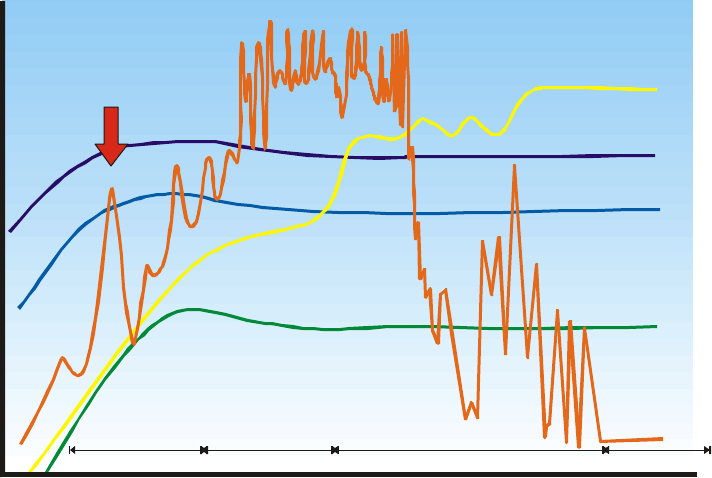
Oxygen Absorption Spectrum: By far the most limiting factor for RF transmission in
the new 59.05 to 64GHz ISM band is the effect of oxygen absorption on the transmitted
signal. Figure 1; below, details the absorptive properties of atmospheric O2 at a center
frequency of 60GHz (indicated by the red arrow).
Fig. 1 Oxygen Absorption Properties
Fortunately, the atmospheric concentration of naturally occurring diatomic oxygen (O2)
is relatively constant and expected absorption can be modeled accurately. In addition, the
absorptive properties of oxygen dramatically reduce the likelihood of converging
interfering signals.
The effects of oxygen absorption, while a curse for those seeking long-distance
transmissions, is a blessing for those seeking interference free wide-band RF connections
up to 1 mile in range.
CO
2
CO
2
O
3
O
2
O
2
HO
2
HO
2
HO
2
HO, CO
22
HO
2
HO
2
HO
2
DRIZZLE (0.25mm/hr)
Millimeter
10 GHz
3 cm
0.1 dB/Km
1 dB/Km
10 dB/Km
100 dB/Km
1,000 dB/Km
100 GHz
3 mm 1 THz
0.3 mm 10 THz
30 m
µ
100 GHz
3 m
µ
1,000 GHz
0.3 m
µ
Submillimeter Infrared Visible
HEAVY RAIN
(25mm/hr)
Visibility 50m FOG
(0.1g/m )
3
EXCESSIVE RAIN
(150mm/hr)
Installation and Operation Manual; Version 1.1 May 22, 2000
Harmonix Corp.
1755 Osgood St.
N. Andover, MA 01845
(978) 974 0931, (978) 974 0969 fax
www.hxi.com
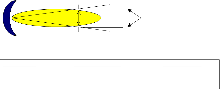
Antenna Gain / Antenna Beamwidth:
To increase the level of RF energy available to the radio receiver, Harmonix employs
high performance high gain (directivity) antennae specifically selected for a given range.
The gain of an antenna is increased by focusing the RF energy into a more confined
pattern beamwidth. The antenna beamwidth is defined in degrees of an arc between to
end points where the signal level is half that at the center of the beam (-3dB).
Antenna radiation Pattern
)
The relationship between antenna gain and beamwidth for standard GigaLINK antenna
configurations is detailed below.
Configuration Antenna Gain (dBi) 3dB Beamwidth
Standard Patch > 30dBi 3.5°
13” Parabola > 38dBi 1.7°
As shown in the diagram above, as the distance from the transmitter increases the size of
the 3dB radiation pattern increases as a factor of the beamwidth. The signal however, is
attenuated quickly in free space predominately by the effects of oxygen absorption in the
59-64GHz ISM Band (16dB/KM).
During terminal alignment, the challenge is to focus the transmitter as precisely as
possible onto the center of the receiving antenna. The received signal strength drops by
half between the center point of focus and the 3dB edges of the receive pattern “spot”.
Signal level 3dB points
Beamwidth °
°°
°
Installation and Operation Manual; Version 1.1 May 22, 2000
Harmonix Corp.
1755 Osgood St.
N. Andover, MA 01845
(978) 974 0931, (978) 974 0969 fax
www.hxi.com
Section 3. GigaLINK System Basics
Both the transceiver terminals and power supply boxes provided with the GigaLINK
system are fully self-contained and sealed. There are no field level repairs or adjustments
authorized on these devices. Opening the housing of the radio terminal is a violation of
non-disclosure policy, will void the equipment warranty and is a direct violation of FCC
Part 15 regulations.
The Harmonix GigaLINK system is shipped as a complete kit with everything necessary
to complete a successful installation. The certified installer must only obtain AC power
and the required network fiber services terminated with the proper termination style.
Standard mounting systems are provided based on the antenna configuration chosen for
the specific path.
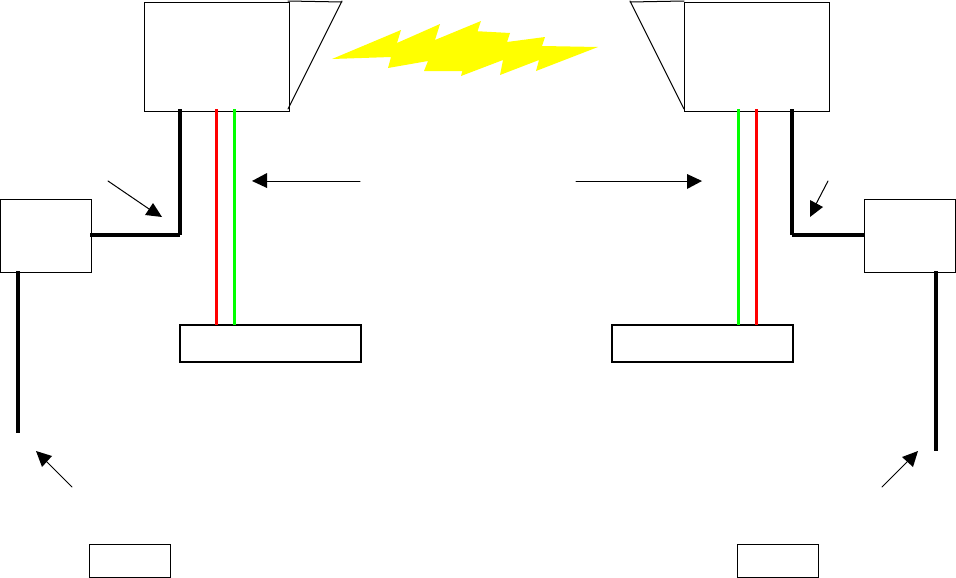
Installed GigaLINK System Block Diagram:
DC Cable DC Cable
AC Power Service AC Power Service
Site #1 Site #2
GigaLINK
High-band
Terminal
GigaLINK
Low-band
Terminal
Power
Supply Power
Supply
N
etwork Device
N
etwork Device
RX/TX Fiber
Network Interface

Installation and Operation Manual; Version 1.1 May 22, 2000
Harmonix Corp.
1755 Osgood St.
N. Andover, MA 01845
(978) 974 0931, (978) 974 0969 fax
www.hxi.com
GigaLINK System Installation Kit Component List
Item Description Qty Supplied Re-Order #
1. GigaLINK Radio Transceiver (High-band) 1
2. GigaLINK Radio Transceiver (Low-band) 1
3. GigaLINK DC Power Supply 2
4. Power Supply Cable Assy. (1.8m) 2
5. Fiber Loop-back Jumper 2
6. SMA AGC Monitor Pigtail 2
7. Pan & Tilt Terminal Mount 2
8. Pipe Mount Bracket with U-Bolts & hardware 2
9. Terminal Mount Hardware Kit (stainless) 2
10. GigaLINK Installation/Operation Manual 2
Insert Section for optional Installation Components
Installation and Operation Manual; Version 1.1 May 22, 2000
Harmonix Corp.
1755 Osgood St.
N. Andover, MA 01845
(978) 974 0931, (978) 974 0969 fax
www.hxi.com
Section 4; GigaLINK Installation Procedure
Confirming Line of Sight (LOS)
Without exception all microwave and millimeter wave wireless systems require
unobstructed “Line of Sight” to operate reliably. In most cases, LOS can be confirmed
visually, particularly in the case of a short-range product like the Harmonix GigaLINK
system where both ends of a proposed link should fall within visual range.
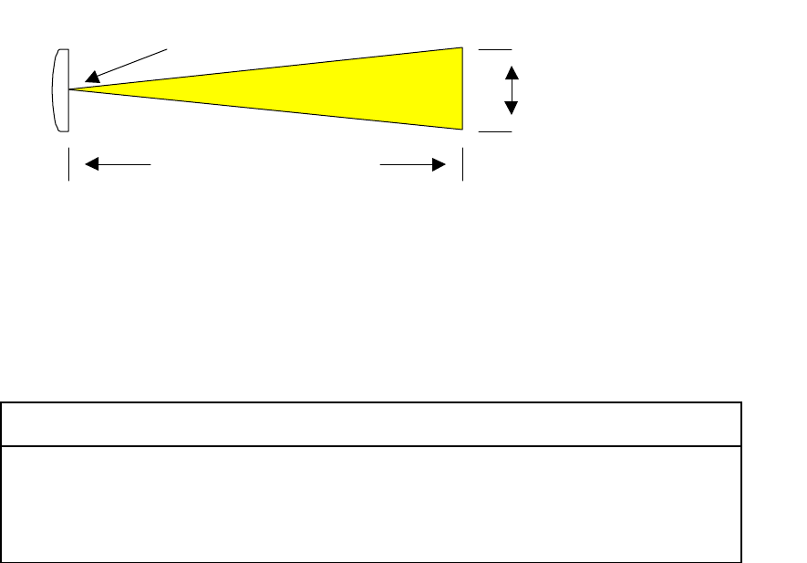
As noted in the previous section, the spot size of the 3dB antenna transmission pattern
increases proportionately with range. Therefore, it is important to insure that the RF path
is clear of obstructions for the entire 3dB beamwidth at any point along the transmission
path. The diagram and formula shown below can be used to determine necessary
clearance at any point along the RF path.
Emitter
Where; tan ∅
∅∅
∅°
°°
°/2 = r/d,
And r = d * tan ∅
∅∅
∅°
°°
°/2
And (2) r = Receive Spot Diameter
GigaLINK Receive Area at Maximum rated Ranges:
GigaLINK
Antenna Style Antenna
Beamwidth Distance
(Meters) Spot Diameter
(Meters) Spot Diameter
(Feet)
Patch 30dBi 3.5°400 24.44 80.19
13" Parabola 38dBi 1.7°800 23.74 77.89
Distance =
d
Pattern Beamwidth = ∅
∅∅
∅°
°°
°
3dB Receive radius = r
Installation and Operation Manual; Version 1.1 May 22, 2000
Harmonix Corp.
1755 Osgood St.
N. Andover, MA 01845
(978) 974 0931, (978) 974 0969 fax
www.hxi.com
Relative Signal Strength Distribution of Circular Receive Area
Path Engineering/Fade Margin Budgeting:
Unlike traditional microwave and wireless systems, the Harmonix GigaLINK system is
designed to provide 99.99% statistical availability when used within the maximum
recommended range envelope. Therefore, no complex calculations to account for free
space losses or rain fades are required. The maximum recommended range limits were
calculated for a minimum fade margin of 10 dB under the worst rain conditions possible
(25mm/hr.). In practice, except for ranges at the extreme limit of the envelope, actual
fade margins will be higher.
The most critical factor in achieving the desired reliability level is precision of the
antenna alignment during installation. Failure to align both terminals on the center
(optimum) region of the receive area will greatly reduce the level of signal received and
in turn the available fade margin. Likewise, if the GigaLINK terminals are not mounted
securely enough, misalignment from terminal movement due to wind or vibration can
also result in unreliable operation.
Area of detectable
signal level
Area of usable
signal level
Area of Optimum
(peak) signal level
Receive Pattern
3dB points
Installation and Operation Manual; Version 1.1 May 22, 2000
Harmonix Corp.
1755 Osgood St.
N. Andover, MA 01845
(978) 974 0931, (978) 974 0969 fax
www.hxi.com
Selecting GigaLINK
Terminal Locations:
Several factors must be considered when selecting each GigaLINK terminal location. The
ideal location for the GigaLINK terminals is one that provides un-obstructed Line of
Sight and a stable/secure mechanical attachment point. In order of precedence primary
considerations should include.
• Locations with unobstructed Line of Sight to target terminal
• Locations affording secure mechanical mounting provisions
• Locations isolated from sources of vibration
• Locations away from possible moving obstructions (workers, cranes etc.)
• Locations accessible to service personnel for maintenance
• Locations convenient to necessary power and network services.
Harmonix supplies several installation kits for a variety of mounting techniques. The best
mounting location and attachment method should be determined prior to equipment order
during a detailed site survey.
Selecting the Optimum Terminal Mounting Method:
The following sections detail available mounting methods and hardware for the
GigaLINK product. Mounting hardware to be specified at time of order.
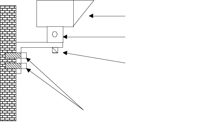
Figure 1. Standard Wall Mount (all hardware included)
GigaLINK Transceiver
Elevation Adjustment
Azimuth Adjustment
Stainless Steel Bolts ½” Minimum OD
With wall anchors, or through bolt to
backing plate
Installation and Operation Manual; Version 1.1 May 22, 2000
Harmonix Corp.
1755 Osgood St.
N. Andover, MA 01845
(978) 974 0931, (978) 974 0969 fax
www.hxi.com
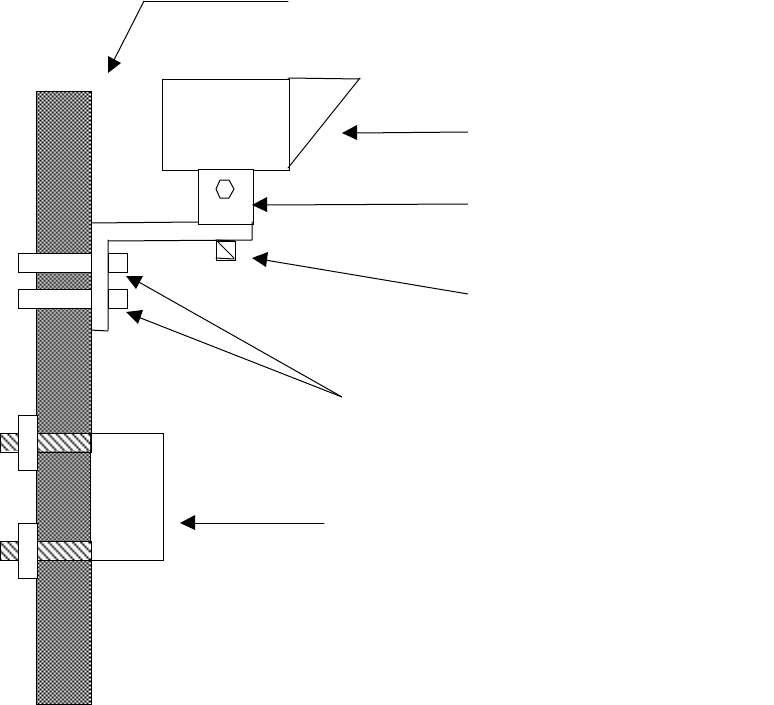
Figure 2. Standard Pipe Mount (all hardware included)
Pipe (structural steel) 2.5” – 4.5” OD
Power Supply Bolted to Uni-Strut
Sections (hardware supplied)
GigaLINK Transceiver
Elevation Adjustment
Azimuth Adjustment
Stainless Steel U- Bolts (Supplied)
Installation and Operation Manual; Version 1.1 May 22, 2000
Harmonix Corp.
1755 Osgood St.
N. Andover, MA 01845
(978) 974 0931, (978) 974 0969 fax
www.hxi.com
Mechanical Installation:
Once the optimum terminal locations have been selected, it is recommended that both
terminals be mechanically installed. The hardware kits(s) specified at the time of order
will contain all the necessary piece parts to accomplish a stable installation. The
mechanical installation should progress as follows and be completed prior to radio
“power-up”.
1.) Attach “L” Bracket to Pipe or Wall using recommended attachment method
(U-Bolts, Through Bolts with Backing Plate or Wall Anchors)
2.) Attach Power Supply Box within 1M of radio terminal using Uni-Strut kit for
Pipe mount or Wall Anchor kit for power supply wall mount. Once the power
supply boxes have been installed electrical services can be connected by
facility electricians.
3.) Install GigaLink Terminal to “L” Bracket using supplied pivot bolt and
washers.
4.) Install Network Service (TX/RX Fiber) to GigaLINK Terminal (Fig. 6.)
5.) With power supply switch in the “OFF” position, install DC Power Cable
between Power Supply and Radio Terminal.
6.) Visually align radio terminals to each other as accurately as possible and
temporarily tighten adjustment bolts.
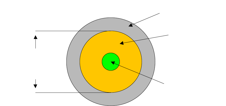
Fig. 6. DC Power and Network Connections (Bottom of GigaLINK Terminal);
SMA AGC Monitor Port DC Power Cable
Fiber to Network RX
p
ort
Elevation Ad
j
ustment Bracket
Fiber to Network TX
p
ort
IN OUT
Installation and Operation Manual; Version 1.1 May 22, 2000
Harmonix Corp.
1755 Osgood St.
N. Andover, MA 01845
(978) 974 0931, (978) 974 0969 fax
www.hxi.com
Required Installer Equipment
The Harmonix GigaLINK system was designed to require a minimum of specialized
equipment for installation, precision alignment and maintenance. A comprehensive, step-
by-step troubleshooting guide with detailed test procedures and additional equipment
recommendations is included in a later section of this manual.
RF Terminal Alignment:
After completing the initial mechanical installation and visual alignment steps the
GigaLINK radio system is ready for final precision alignment. In order to complete
precision alignment, Electrical service must be available at the power supply box and the
DC power cable installed. Final alignment is performed on each terminal separately, by
making very small alignment adjustments to optimize (peak) the received signal level.
Each terminal alignment will be made in two steps.
Step #1 Elevation (Vertical) Alignment
Step #2 Azimuth (Horizontal) Alignment
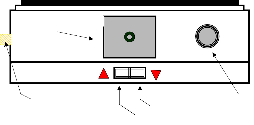
AGC Monitor Port
To facilitate terminal alignment and to provide a quantitative measurement of alignment
quality, the Harmonix GigaLINK terminal is provided with an AGC output monitor port.
The AGC monitor port provides a positive voltage range of 3 – 4 volts DC to indicate the
power level of the received signal. A simple self-ranging digital multimeter is all that is
necessary to monitor the AGC level. Harmonix provides a SMA Male to pigtail jumper
for attachment to the digital multimeter. The AGC monitor port is the primary tool for
precision alignment and provides a tangible measurement to verify alignment during
future maintenance visits.
Loop-Back Fiber Jumper
Also included in all Harmonix Installation kits is a fiber jumper of the correct mode and
termination type. This fiber jumper is used to “Loop-back” GigaLINK terminals during
alignment.
Installation and Operation Manual; Version 1.1 May 22, 2000
Harmonix Corp.
1755 Osgood St.
N. Andover, MA 01845
(978) 974 0931, (978) 974 0969 fax
www.hxi.com
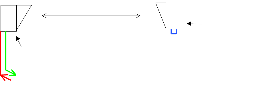
Generating Modulation for the Purposes of Terminal Alignment:
In the absence of actual network traffic, a modulation must be applied at the terminal
“IN” port to excite the radio fiber modem and modulate a transmitted signal. This
modulation can be created by artificial means to drive the radio transmitter to a high
enough RF level to facilitate alignment.
Harmonix offers GigaLINK models in (3) popular data protocols 100Mbps FX, OC3 and
OC12. An OC3 modulation source is suitable for modulating all three protocols for the
purposes of alignment only. Harmonix recommends the FLUKE OC3Port Plus
OC3/ATM Handheld Test set for this application. In addition, depending on the
intelligence and built in test capability of the customer premises equipment, a suitable test
signal may be available from the network hub, switch or ATM switch.
Block Diagram of Test set-up for Final Alignment
Once a suitable modulation source has been obtained and the GigaLINK Terminals have
been configured in accordance with figure 6, final alignment can begin. Follow the
specific steps as detailed on the following page to achieve final (precision) alignment.
Remote
GigaLINK
Terminal with
Fiber Jumper
installed
and Power on.
Modulation
Source
GigaLINK Terminal to be
Aligned with Modulation
Source connected and
Power on.
Installation and Operation Manual; Version 1.1 May 22, 2000
Harmonix Corp.
1755 Osgood St.
N. Andover, MA 01845
(978) 974 0931, (978) 974 0969 fax
www.hxi.com
Elevation Alignment
Assuming that a rough mechanical alignment for both azimuth and elevation were
performed as outlined in the previous section, elevation alignment can now be performed.
The following steps detail the elevation alignment procedure. Best results will be
achieved when care is taken to make small incremental adjustments. Small adjustment at
the radio terminal translate to much larger changes at the remote terminal.
1.) Slightly loosen the (4) 13mm bolts that lock the elevation adjustment bracket.
2.) Measure the voltage present at the AGC monitor port via pigtail and multimeter.
3.) Slowly tilt radio up or down until increasing AGC voltage is observed. Continue
minute adjustment until voltage begins to fall, then return to the position where
the highest voltage was observed.
4.) When satisfied that peak voltage has been achieved tighten top (2) elevation
adjuster bolts to maintain position.
Azimuth Alignment
After completing the initial elevation adjustment, azimuth alignment can proceed.
1.) Slightly loosen the single 13mm bolt that locks the azimuth adjustment to the “L”
Bracket.
2.) Measure the voltage present at the AGC monitor port via pigtail and multimeter.
3.) Slowly rotate radio left or right until increasing AGC voltage is observed.
Continue minute adjustment until voltage begins to fall, then return to the position
where the highest voltage was observed.
5.) When satisfied that peak voltage has been achieved tighten azimuth adjuster bolt
to maintain position.
When the initial azimuth alignment has been completed repeat the elevation alignment
again followed by the azimuth alignment until confident that the AGC voltage is peaked.
Repeat the procedure outlined above for the remote terminal following the same
methodology. In most cases several incremental alignments in both planes at both
terminals will be necessary to achieve optimum alignment for the link.

Installation and Operation Manual; Version 1.1 May 22, 2000
Harmonix Corp.
1755 Osgood St.
N. Andover, MA 01845
(978) 974 0931, (978) 974 0969 fax
www.hxi.com
Peak AGC Voltages for Model# vs. Range
Model No. 200M 400M 800M 1,000M 1,200M 1,400M
100-0400-MM N/A N/A N/A N/A
100-0800-MM N/A N/A N/A
155-0400-MM N/A N/A N/A N/A
155-0800-MM N/A N/A N/A
155-0400-SM N/A N/A N/A N/A
155-0800-SM
622-0200-MM N/A N/A N/A N/A N/A
622-0400-MM N/A N/A N/A N/A
622-0800-MM N/A N/A N/A N/A
622-0200-SM N/A N/A N/A N/A N/A
622-0400-SM N/A N/A N/A N/A
622-0800-SM N/A N/A N/A N/A