HYT Science and Technology Co TM-610V Mobile Radio User Manual
Shenzhen HYT Science &Technology; Co Ltd Mobile Radio
Contents
- 1. Adjustment Guide
- 2. Users Manual
Adjustment Guide
TM-610 Adjustment Description
This mobile radio can be adjusted via programming software or manually. The manual
adjustment procedures are listed below. (please refer to “test mode” and “adjustment
mode” in Mobile Radio Mode.
Tools:
Radio Communication Test Set a set
Spectrum analyzer a set
20A/30V power supply aset
Wattmeter a set
Signal line (with dummy load) a piece
Procedures:
1. Download:
¾ Connect the mobile radio with PC via programming software and turn on the radio.
¾ Click “Download” on the software interface;
¾ Select your desired program and click “begin” to begin download;
¾ Click “Close" when the program is fully downloaded.
¾ Turn off the radio and plug the programming cable out.
2. Initialization:
¾ The necessary information hasn’t been imbedded into the Flash of the radio when it
leaves the factory. So users need to adjust the frequency and initialize the radio
before adjustment;
¾ Press [P2] to power the mobile radio on. Press [P4] when “DESINAO” is displayed;
¾ The LED on the control panel stops flashing when initialization process is finished.
3. Adjustment (Part of the adjustment items can be adjusted in conventional mode while
other should be adjusted manually.)
¾ Turn on the mobile radio to enter conventional mode;
¾ Power your mobile radio off and press [PF1] to restart the radio to adjust other items.
The channel number will be displayed on LED;
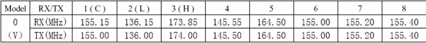
¾ Frequency chart:
TM-610V:136-174;
VCO Adjustment
Measurement Adjustment
Item Condition
Test Instrument Terminal Part Method
Specifications
/Remarks
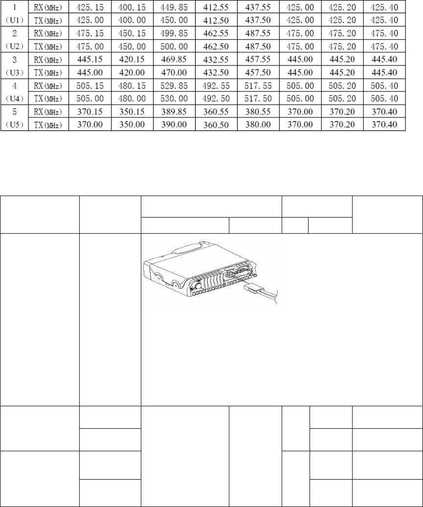
1. Power supply
1. Power
supply: 13.6 V
DC
Note: 1. This mobile radio only can be installed in a minus grounding
power system. Reverse polarity will cause the cable fuse to blow. Check
the vehicle ground polarity before the installation to avoid wasted time
and effort.
2. IF DC power is to be controlled by the vehicle ignition switch, a switch
relay should be used to switch the positive power lead. The vehicle
ignition switch then controls DC to the relay coil.。
1.CH:TX HI 6.0V±0.1V
2. VCO Latch
voltage (TX) 2.CH:TX LO
TC1
Check >1.0V
1.CH:RX HI 6.0V±0.1V
3. VCO Latch
voltage (RX) 2.CH:RX LO
Digital voltmeter CV
TC2
Check >1.3V

Transmitter Adjustment
Measurement Adjustment
Item Condition
Test Instrument Terminal Part Method
Specifications/
Remarks
4. TX
Frequency
Not enter adjustment
item, but switch to 2CH
Radio
Communication
Test Set
ANT Adjust VR801
Adjust channel
frequency
Error<50Hz
High Power:
PO=23~25WW
I≤8.0A
Check High
Power
5. TX Power
Each CH corresponds
to a specific TX freq;
enter the item “0”, ‘1” in
turn, to adjust High/Low
power.
Radio
Communication
Test Set
Ammeter
ANT
Adjust software
setting &
VR101; press
[P2] to save the
setting and
move to the
next item.
Low Power:
PO=5±0.5W
I≤5.0A
Check Low
Power
Check the deviation of
Hi/Mid/Low channel:
4.0±0.1KHz(W)
Check the deviation of
Hi/Mid/Low channel:
2.4±0.1KHz(W)
6. Max.
Deviation
1. Each CH
corresponds to a
specific TX freq; enter
the item “2” and adjust
“0.”、 “1.”、 “2.”、 “3.”、
“4.”
Radio
Communication
Test Set
Filter:
0.05-15KHz
AF:1KHz
75mV
ANT
MIC Jack
Adjust software
setting; press
[P2] to save the
setting and
move to the
next item. Check the deviation of
Hi/Mid/Low channel:
1. 9±0.1KHz (N)
7. Modulation
Sensitivity
Check deviation:
2.6KHz-3.4KHz (W)
2.2KHz-2.7KHz (M)
1.3KHz-1.7KHz (N)
8. Modulation
Distortion
1. Each CH
corresponds to a
specific TX freq.
Radio
Communication
Test Set
Filter:
0.05-15KHz
AF: 1KHz
7.5mV
ANT
MIC Jack
≤5%
Check
9. CDCSS
Balance
Each CH corresponds
to a specific TX freq;
enter item “3”
Radio
Communication
Test Set
Filter
LPF: 300Hz
ANT
Use “UP”, “DN”
key to set
CDCSS
Check
waveform
10. CTCSS Each CH corresponds Radio ANT Use “UP”, “DN” Adjust deviation to

Deviation to a specific TX freq;
enter item “4”, “5”, “6”;
adjust
67Hz/151.4Hz/254.1Hz
CTCSS
Communication
Test Set
Filter
LPF: 300Hz
key to set
CDCSS
0.75KHz±0.10KHz
(W)
0.60KHz±0.10KHz
(M)
0.37KHz±0.05KHz (N)
11. CDCSS
Deviation
Each CH corresponds
to a specific TX freq;
enter item “7"
Radio
Communication
Test Set
Filter
LPF: 300Hz
ANT
Use “UP”, “DN”
key to set
CDCSS
Adjust deviation to
0.75KHz±0.10KHz
(W)
0.60KHz±0.10KHz
(M)
0.37KHz±0.05KHz (N)
12.DTMF
Deviation
Each CH corresponds
to a specific TX freq;
enter item “8"
Radio
Communication
Test Set
Filter
LPF: 3KHz
ANT
Use “UP”, “DN”
key to set
CDCSS
3.0KHz±0.1KHz (W)
2.4KHz±0.1KHz (M)
1.5KHz±0.1KHz (N)
13. MSK
Each CH corresponds
to a specific TX freq;
enter item “9"
Radio
Communication
Test Set
Filter
LPF: 3KHz
ANT
Use “UP”, “DN”
key to set
CDCSS
3.0KHz±0.1KHz (W)
2.4KHz±0.1KHz (M)
1.5KHz±0.1KHz (N)
14. Single
tone
(2-/5-tone)
Each CH corresponds
to a specific TX freq;
enter item “A"
Radio
Communication
Test Set
Filter
LPF: 3KHz
ANT
Use “UP”, “DN”
key to set
CDCSS
Adjust deviation to
3.0KHz±0.10KHz (W)
2.4KHz±0.10KHz (M)
1.5KHz±0.1KHz (N)

Receiver Adjustment
Measurement Adjustment
Item Condition
Test Instrument Terminal Part Method
Specifications/
Remarks
15. RF
bandpass filter
Enter item “B”; Each CH
corresponds to a specific
TX freq.
Scanner ANT . TP1
First
manually
adjust
TC101, then
the software
setting
Set the gain
value to the
max; the
corresponding
freq is on the
rightmost of
the bandpass
wave. Press
[P2] key to
save.
16. Max.
SINAD
Frequency: RX Center;
adjust to CH1(C);
corresponds to a specific
freq.
Radio
Communication
Test Set
SSG Output:
-47dBm
MOD: 1KHz
DEV: ±3KHz(W)
±1.5KHz(N)
Filter:
0.3-3.0KHz
ANT
SP Jack
K301
Check Max.
volume:
4.6V or above
1. CH: RX Center,
manually adjust to CH
1(C).
2. CH: RX LO, manually
adjust to CH 2 (L).
17. Sensitivity
3. CH: RX HI, manually
adjust to CH3 (H).
Radio
Communication
Test Set
SSG Output:
-116dBm
MOD: 1KHz
DEV: ±3KHz(W)
±2.4KHz(M)
±1.5KHz(N)
Filter:0.3-3.0KHz
ANT
SP Jack
Wide/narro
w
band switch
(turn on the
power while
holding [P1]
key to enter
CH setting
mode)
[P2] key for CH
adjustment
Check
SINAD:
12dB or above

Radio
Communication
Test Set
SSG Output:
-119dBm (Level 3)
19. SQ Open
Enter in turn the item “C”
(Level 9 on), “D” (Level 3
on); adjust CH to “0.”, “1.”,
“2.”, “3.”, “4.”
SSG Output:
-112dBm (Level 9)
No need to
adjust software
setting at SQ
Level 3/9;
press [P2]
twice to save.
Continuously
press[P2] key
twice for CPU
reading and
writing; SQ level
Radio
Communication
Test Set
SSG Output:
-123dBm (Level 3)
20. SQ Close
Enter in turn the item “C”
(Level 9 off), “D” (Level 3
off); adjust CH to “0.”, “1.”,
“2.”, “3.”, “4.”
SSG Output:
-115dBm (Level 9)
ANT
SP Jack
Adjust
software
setting No need to
adjust software
setting at SQ
Level 3/9;
press [P2]
twice to save.
Continuously
press[P2] key
twice for CPU
reading and
writing; SQ
level
21. Distortion DIS≤5%
22. S/N
1. Channel: RX Center
Radio
Communication
Test Set
SSG Output:
-60dBm
ANT
SP Jack
Filter:
0.3-3.0KHz
Check S/N≥47 (W)
S/N≥42 (N)
Note: The radio must be covered with aluminum chassis during the adjustment of
sensitivity, Tx power, signalling waveform, frequency deviation, Rx Squelch. Connect an
RF power meter to the antenna connector during transmission. Connect the SINAD meter
with 16ohm load to the external [SP] Jack.