Hangzhou Gubei Electronics Technology 3301SBSL WT1SBSL User Manual
Hangzhou Gubei Electronics Technology Co.,Ltd WT1SBSL
Contents
- 1. Users Manual
- 2. User manual_1
User manual_1

BiTrend™ EssentialSeriesWi-Fi Module
User Manual
WT1SBSL

1www.ibroadlink.com
Hangzhou Gubei Electronics Technology Co., Ltd.
Copyright Information
The information contained in this document is the proprietary information of Hangzhou Gubei
Electronics Technology Co., Ltd. (hereinafter referred as BroadLink). Further, no portion of this
document may be altered or edited in any form or by any meanswithout the prior written
consent of BroadLink, the copyrightholder.
Further BroadLink reserves the right to make modifications, additions anddeletions to this
document due to typographical errors, inaccurate information, orimprovements to products
mentioned in the document at any time and without notice. Such changes will, nevertheless be
incorporated into new editions of this document or published as errata sheet.
Version History
V 1.0.0 22/01/2016 1stissue of preliminary document

2www.ibroadlink.com
Table of Contents
1. Introduction.................................................................................................................................3
1.1 Overview............................................................................................................................3
1.2 Applications.......................................................................................................................4
1.3 Key Features......................................................................................................................4
2. Product Overview.......................................................................................................................5
2.1 Product Picture.................................................................................................................5
2.2 Block Diagram...................................................................................................................5
3. Electrical Characteristics.............................................................................................................6
3.1 Absolute Maximum Ratings – Voltage & Current........................................................6
3.2Current consumption........................................................................................................6
3.3 Absolute maximum ratings – Temperature...................................................................7
3.4Absolute maximum ratings – ESD...................................................................................7
4. Module Interfaces.......................................................................................................................8
4.1 PIN Layout.........................................................................................................................8
4.2 PIN Definitions..................................................................................................................8
5. Reference Design........................................................................................................................9
6. AntennaCharacteristics............................................................................................................
10
6.1 Antenna Selection..........................................................................................................10
6.2 Minimizing Radio Interference.....................................................................................11
6.3 Specification of On-Board Antenna.............................................................................12
Appendix A Glossary(Quentin respible)...............................................................................13
Appendix B Reference paper(Quentin respible)..................................................................15
Contact Us.....................................................................................................................................16

3www.ibroadlink.com
1. Introduction
1.1 Overview
BiTrend™ Essentialis the industrial leading 2.4Ghz 802.11 b/g/n embedded Wi-Fi module which
delivers unmatched performance and codeless development in a compact package, providing
a quick, easy and cost effective way for developers and manufacturers to add Wi-Fi connectivity
for home automation, lighting control, energy efficiency and other IOT applications.
BiTrend™ Essential family combines a 2.4Ghz 802.11 b/g/n radio transceiver with a 32-bit
microprocessor and embedded with MAC, baseband processing and optimized Wi-Fi network
stack. It is an ideal solution for developers and manufacturers with limited RF and embedded
programming expertise as it significantly reduces RF design time and removes the burden of
testing and certification.
Benefitted from BroadLink’s turn-key solution, BiTrend™ Essential is an ideal solution for
developers with limited Wi-Fi or RF expertise or for those seeking faster time to market. It
reduces RF design time and removes the burden of testing and certification. BiTrend™ Essential
is fully compliant with IEEE 802.11 b/g/n standard and certified with CE, FCC and RoHS.
BiTrend™ Essential is a highly integrated Wi-Fi SoC(system on Chip) single chip, which
supportsIEEE802.11b/g/n single stream, providing GPIO for intelligent control, and UART
interfaces for device communication.
BiTrend™ Essential has 8Mbits flash and integrates power amplifier, low noise amplifier, and RF
switch to reduce the module size and RF design capability required. And also integrate power
manage unit for single 3.3V power source for cost effective design.
BiTrend™ Essential embedded 32-bit RISC MCU for 802.11b/g/n drivers, supplicant, TCP/IP
protocol stack, and networking applications, can be operated in station mode and softAP mode.
The WT1SBSL is an ideal solution for embedded device to enable networking service with
minimized design effort.

4www.ibroadlink.com
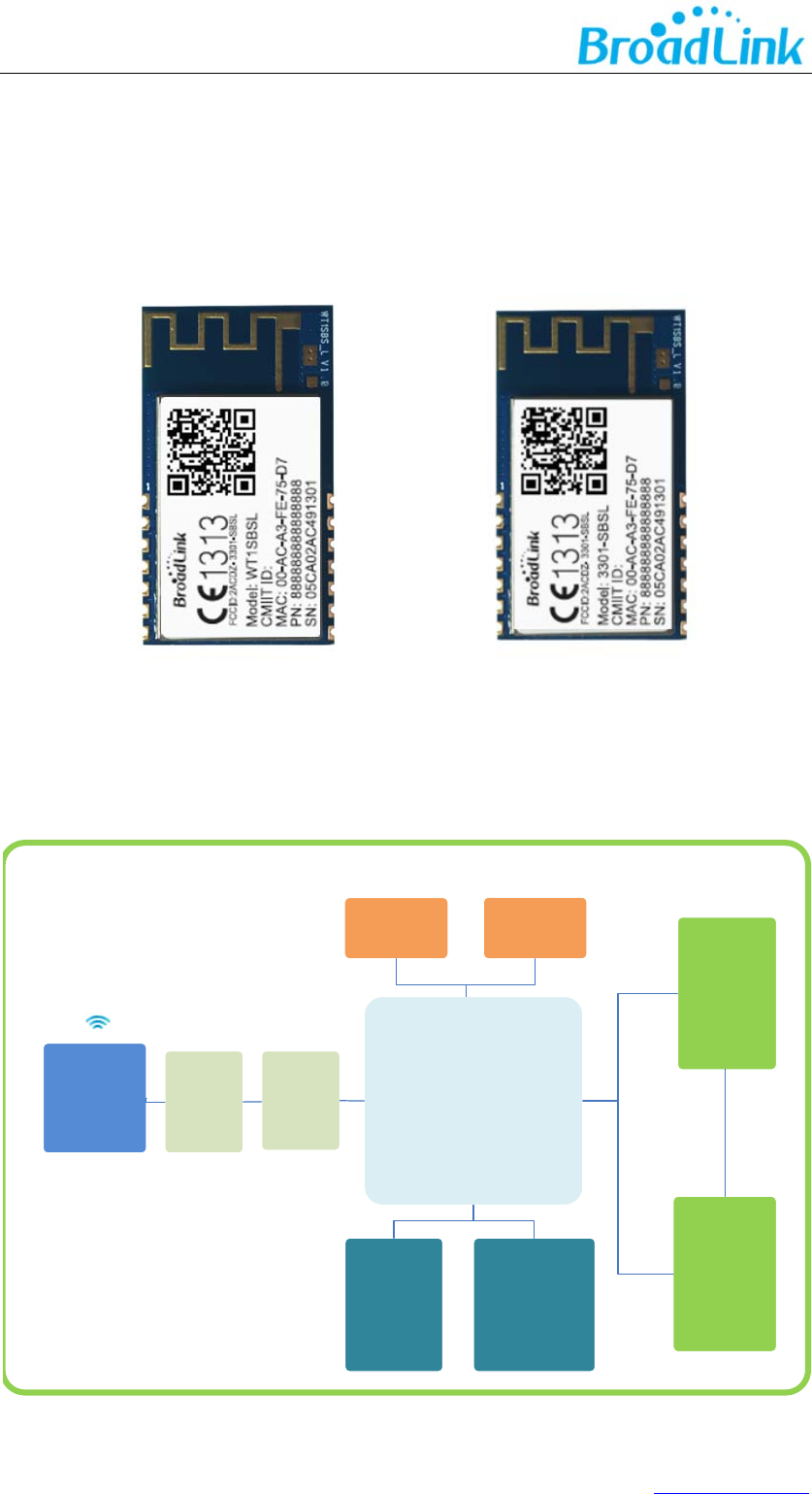
RF
receiver
RF
transmitter
Baseband
MAC /
Packet
buffer /
security
engine
UART
System
control
RF_IN
RF_OUTP
RF_OUTN
UART
GPIO/LED
Figure 1. WT1SBSL block diagram
1.2 Applications
Smart home appliances
Remote Control
Medical/Health Care
Network consumer devices
1.3 Key Features
a. Support IEEE802.11b/g/n
b. Support UARTtransparent transfer
c. Support STA\AP
d. Patent SmartConfig™ technology
e. Support IPv4, TCP/UDP/ DNS/DHCP
f. PCB printed antenna
g. Power source: 3.3V
h. Peripherals:
1*UART
5*GPIO
1*RESET
i. Dimension 31mm*17.7mm*3.6mm
j. ESD: 2KV
k. Absolute maximum ratings
5www.ibroadlink.com
2. Product Overview
2.1 Product Picture
2.2 Block Diagram
MTK7681
802.11 b/g/n
SoC
SPI
FLASH
Balun
Circuit
40MHz
OSC
Reset
Multiplex
Circuit
UART
Filter
Circuit
PCB
Antenna
GPIO
6www.ibroadlink.com
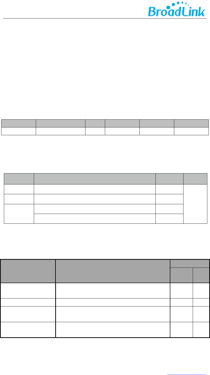
3. Electrical Characteristics
3.1 Absolute Maximum Ratings – Voltage & Current
Using products above the absolute maximum ratings may cause permanent damage to the
device. These are maximum ratings only and functional operation of the device at these
conditions is not implied. Exposure to maximum rating conditions for extended periods may
aect the reliability of the device.
SymbolRatingMINTYPMAXUnit
VDD333.3VSupplyVoltage2.973.33.63V
Symbol
Ra
tings Max
Unit
I
VDD
Tota l currentintoVDDpowerlines(source)
90
mA
I
VSS
Tota l currentoutofVSSgroundlines(sink)
90
I
IO
OutputcurrentsunkbyanyI/Oandcontrolpin
10
OutputcurrentsourcebyanyI/Osandcontrolpin
10
3.2Current consumption
Symbol
Condition
Performance
TYP Unit
I
RF
IDLE mode 80 mA
I
RF
RX Active, HT40, MCS7 151 mA
I
RF
TX HT40, MCS7
@ 15dBm(pulse) 210 mA
I
RF
TX CCK
11Mbps @ 18dBm(pulse) 250 mA
Note: All result is measured at the antenna port and VDD33 is 3.3V

7www.ibroadlink.com
3.3 Absolute maximum ratings – Temperature
Symbol
Rati Max
Unit
T
STG
Storagetemperature –40 to+125
℃
T
A
Workingtemperature -10 to+70
℃
Humidity
Non condensing, relative humidity 90%
(
RH
)
3.4Absolute maximum ratings – ESD
Symbol Ratings Conditions Class Max Unit
V
ESD
(HBM)
Electrostatic discharge
voltage
(human body model)
TA = +25 °C
conforming to
JESD22-A114
2 2000 V
8www.ibroadlink.com
4. Module Interfaces
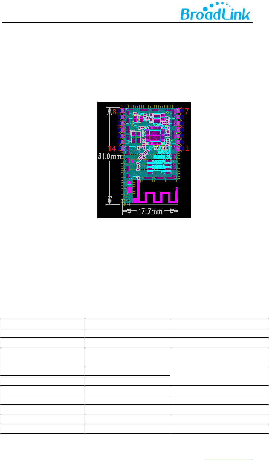
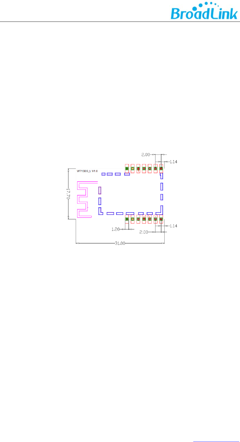
4.1 PIN Layout
WT1SBSL has one group of pins2X7. The layout of PINs are shown in the figure below.
Figure6.
WT1SBSL
pin-out
4.2 PIN Definitions
PIN Assignment
PINPINNAMENOTE
Pin1GND
Pin2VCC3.3V
Pin3RST_NModule software reset,Available
atlowlevel
Pin4UART_TXUARTOnly
forPassthrough
Pin5UART_RX
Pin6GPIO3
Pin7GPIO4Feedwatchdog
Pin8GPIO4Feedwatchdog
Pin9GPIO3
Pin10GPIO2
9www.ibroadlink.com
Pin11GPIO1Module software reset,Available
atHighlevel
Pin12GPIO0UsuallyuseasWi‐FiLED
Pin13VCC3.3V
Pin14GND
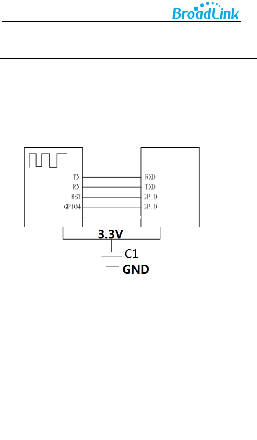
5. Reference Design
In addition to the standard serial port,the peripheral MCU also need to provide two GPIO pins
to connect with the GPIO4 pin and the RST pin of the WIFI module respectively,when the WIFI
module works properly,the GPIO4 pin will keep outputting message of dog feeding,if the
peripheral MCU did not receive the message,the module will reset and restart through pulling
down the RST pin by the other GPIO pin.
If the peripheral MCU uses power source of 5V,it needs to add a level switching circuit in the
connection of the serial port and the related circuit.
The module needs a large current about 250mA when transmitting data,please ensure that the
power source can provide sufficient current.
WIFIMODULE
Peri
p
heral MCU
10www.ibroadlink.com
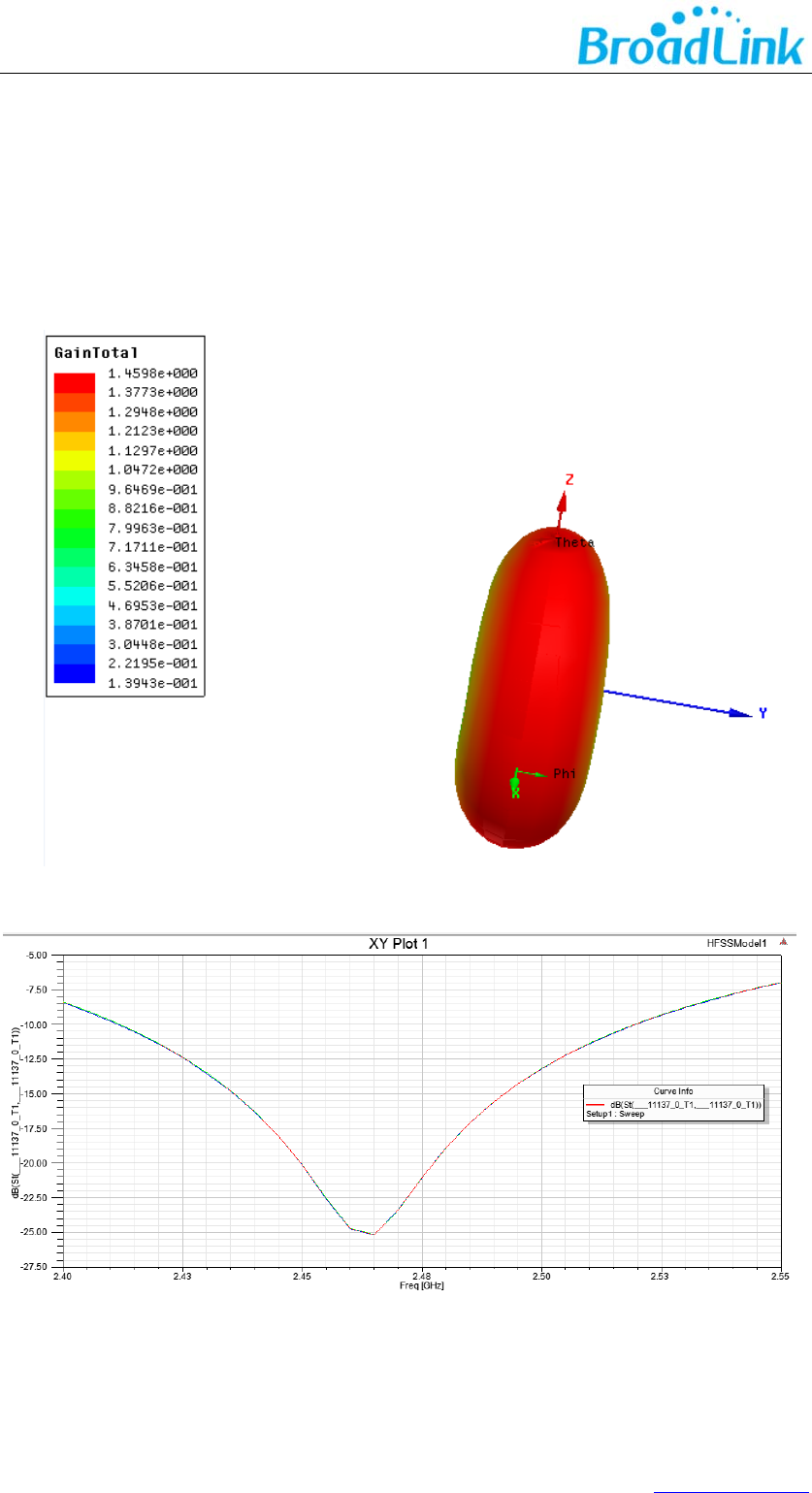
6. AntennaCharacteristics
6.1 Antenna Selection
The WT1SBSL supports on-board PCB printed antenna.When the Operating Frequencyis
between 2.4G~2.5GHz, S11 of antenna port is less than-10dB and peak gainis about 1. 5dBi.
Figure 7. Antenna radiation pattern simulation
Figure 8. Antenna port S11simulation curve
In practical use, WT1SBSL is welded on user’s boardand value of S11 has some changes.
11www.ibroadlink.com
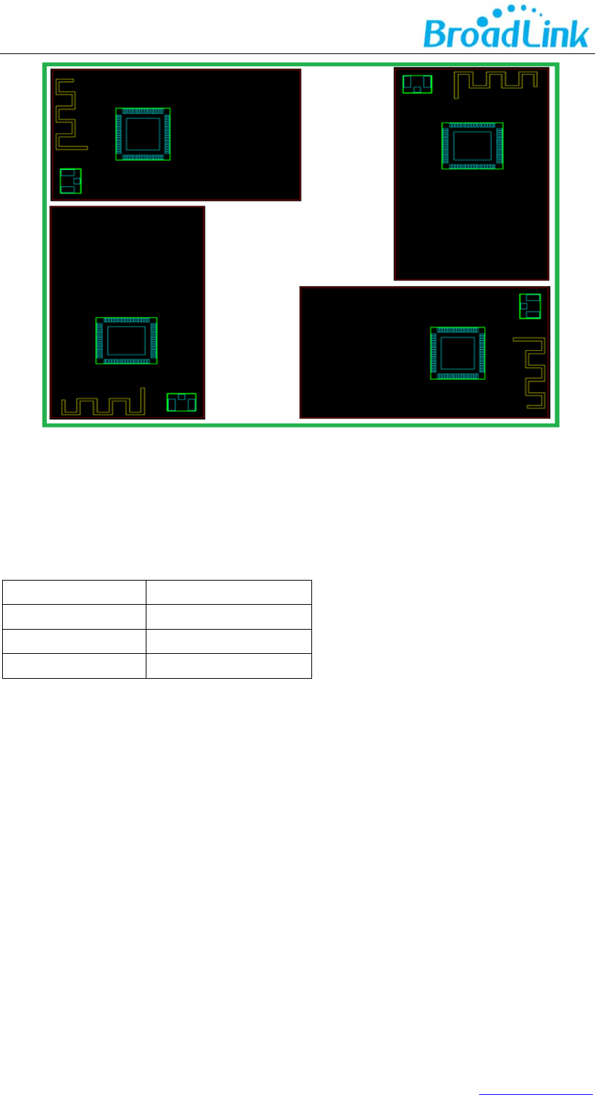
6.2 Minimizing Radio Interference
When integrating the Wi-Fi module with on board PCB printed antenna, make sure the three
points below:
1. The area under the antenna end of the module should be keep clear of metallic components,
connectors, vias, traces and other materials that can interfere with the radio signal.
2. The area around the antenna end the module protrudes at least 10mm from the mother
board PCB and any metal enclosure.
3. When planning PCB layout, it is recommended that user places the antenna of Wi-Fi module
as close as possible to the edge of boarder to ensure the good performance of antenna, which
is shown in the picture below.
12www.ibroadlink.com
6.3 Specification of On-Board Antenna
OperatingFrequency 2.4G~2.5GHz
VSWR(max) 2
Peak Gain 1.45dBi
AntennaType PIFA

13www.ibroadlink.com
Appendix A Glossary(Quentin respible)
ADCAnalog‐to‐DigitalConverter
AESAdvancedEncryptionStandard
ANTAntenna
APWirelessAccessPoint
BPSKBinaryPhaseShiftKeying
DBPSK
Differential binar
y
p
hase shift ke
y
in
g
DC Direct Current
CC
K
ComplementaryCodeKeying
CDMChargeDeviceModel
DHCP
Dynamic Host Configuration Protocol
CMOSComplementaryMetalOxideSemiconductor
DNS
Determination of non-significance
DQPSK Differential quadrature phase shift keying
DSSS Demand assigned signaling and switching subsystem
DTIM
Digital Transmission Interface Module
EMSP Enhanced Modular Signal Processor
ESD Electrostatic Discharge
EVM Error Vector Magnitude
FCC Federal Communications Commission
FER Floating Error
GND Ground
GPIO General Purpose Input/Output
HBM Human body model
IEEE Institute of Electrical and Electrionics Engineers
IO Input/Output
IOT Individual operation test
IPv4 Internet Protocol version 4
LED Light-emitting diode
LVTTL Low Voltage Transistor Transistor Logic
MAC Medium Access Control layer
MCS Modulation and coding scheme
MCU Microcontroller Unit
MIMO Multiple-Input Multiple-Output
MSL Multilayer Switching Protocol
NC Numerical Control
NRST Negative Reset
OF
DM Orthogonal Frequency Division Multiplexing
OSC Oscillator
PCB Printed Circuit Board
PIFA Planar inverted F antenna
QPSK Quadrature Phase Shift Keyin
RC Resistance- capacitance
RF Radio Frequency

14www.ibroadlink.com
RISC Reduced Instruction Set Computer
RoHS Restriction of Hazardous Substances
RX Receiver
SDIO Serial Digital Input/Output
SoC System on Chip
SPDT Single-Pole Double-Throw
SPI Serial Peripheral Interface
STA Spanning Tree Algorithm
TCP Transfer Control Protocol
TKIP Temporal Key Integrity Protocol
T
X
Transmitter
IP Internet Protocol
UART Universal Asynchronous Receiver/Transmitter
UDP User Datagram Protocol
UFL
a miniature coaxial RF connector for high-frequency signals
manufactured by Hirose Electric Group
VSWR Voltage Standing Wave Ratio
WEP Wired Equivalent Privacy
WEPA Welded Electronic Packaging Association
WEP64 64 bit Wired Equivalent Privacy
WEP128 128 bit Wired Equivalent Privacy
WPA2 Wi-Fi Protected Access 2
XTAL External Crystal Oscillator
QAM Quadrature Amplitude Modulation
802.11 b/g/n The IEEE 802.11 b/g/n
15www.ibroadlink.com
Appendix B Reference paper(Quentin respible)
[1] IEEE 802.11b/g/n- published IEEE 802.11-2007wireless networking standard and
published IEEE 802.11-2012 standard for Information technology - Clause 19 of the
publishedIEEE 802.11-2007 standard, and Clause 19 of the published IEEE
802.11-2012 standard.

16www.ibroadlink.com
Contact Us
Hangzhou Gubei Electronics Technology Co., Ltd.
Room 106, Building 1, No. 611 Jianghong Road, Binjiang, Hangzhou, Zhejiang, P.R.China
T: +86-571-85159281 F: +86-571-86631817
E: intl@broadlink.com.cn W: www.ibroadlink.com.cn
ThisdevicecomplieswithPart15oftheFCCRules/IndustryCanadalicence‐exempt
RSSstandard(s).Operationissubjecttothefollowingtwoconditions:(1)thisdevice
maynotcauseharmfulinterference,and(2)thisdevicemustacceptanyinterference
received,includinginterferencethatmaycauseundesiredoperation.
LeprésentappareilestconformeauxCNRd'IndustrieCanadaapplicablesaux
appareilsradioexemptsdelicence.L'exploitationestautoriséeauxdeuxconditions
suivantes:(1)l'appareilnedoitpasproduiredebrouillage,et(2)l'utilisateurde
l'appareildoitacceptertoutbrouillageradioélectriquesubi,mêmesilebrouillageest
susceptibled'encompromettrelefonctionnement.
Changesormodificationsnotexpresslyapprovedbytheparty
responsibleforcompliancecouldvoidtheuser'sauthoritytooperatethe
equipment.
Thisequipmenthasbeentestedandfoundtocomplywiththelimitsfor
aClassBdigitaldevice,pursuanttopart15oftheFCCRules.These
limitsaredesignedtoprovidereasonableprotectionagainstharmful
interferenceinaresidentialinstallation.Thisequipmentgenerates
usesandcanradiateradiofrequencyenergyand,ifnotinstalledand
usedinaccordancewiththeinstructions,maycauseharmfulinterference
toradiocommunications.However,thereisnoguaranteethatinterference
willnotoccurinaparticularinstallation.Ifthisequipmentdoescause
harmfulinterferencetoradioortelevisionreception,whichcanbe
determinedbyturningtheequipmentoffandon,theuserisencouraged
totrytocorrecttheinterferencebyoneormoreofthefollowing
measures:

17www.ibroadlink.com
—Reorientorrelocatethereceivingantenna.
—Increasetheseparationbetweentheequipmentandreceiver.
—Connecttheequipmentintoanoutletonacircuitdifferentfromthat
towhichthereceiverisconnected.
—Consultthedealeroranexperiencedradio/TVtechnicianforhelp.
MPERequirements
TosatisfyFCC/ICRFexposurerequirements,aseparationdistanceof20cmormoreshouldbe
maintainedbetweentheantennaofthisdeviceandpersonsduringdeviceoperation.
Toensurecompliance,operationsatcloserthanthisdistanceisnotrecommended.
Lesantennesinstalléesdoiventêtresituéesdefaconàcequelapopulationnepuisse
yêtreexposéeàunedistancedemoinde20cm.Installerlesantennesdefaconàce
quelepersonnelnepuisseapprocherà20cmoumoinsdelapositioncentraledel’
antenne.
LaFCCdeséltats‐unisstipulequecetappareildoitêtreentouttempséloignéd’au
moins20cmdespersonnespendantsonfunctionnement.
RegionSelection
Limitedbylocallawregulations,versionforNorthAmericadoesnothaveregionselectionoption.
InformationfortheOEMIntegrators
ThisdeviceisintendedforOEMintegratorsonly.Pleaseseethefullgrantof
equipmentdocumentforrestrictions.
LabelInformationtotheEndUserbytheOEMorIntegrators
IftheFCCIDofthismoduleisnotvisiblewhenitisinstalledinsideanotherdevice,
thentheoutsideofthedeviceintowhichthemoduleisinstalledmustbelabelwith
“ContainsFCCID:2ACDZ‐3301SBSLandIC:21239‐3301SBSL”