HARRIS M7200VTAC M7200 V-TAC 700/800 MHz Mobile Radio User Manual Part 90
Harris Corporation M7200 V-TAC 700/800 MHz Mobile Radio Part 90
UserManual.wiki
>
HARRIS
>
M7200VTAC User Manual
Manual
Navigation menu
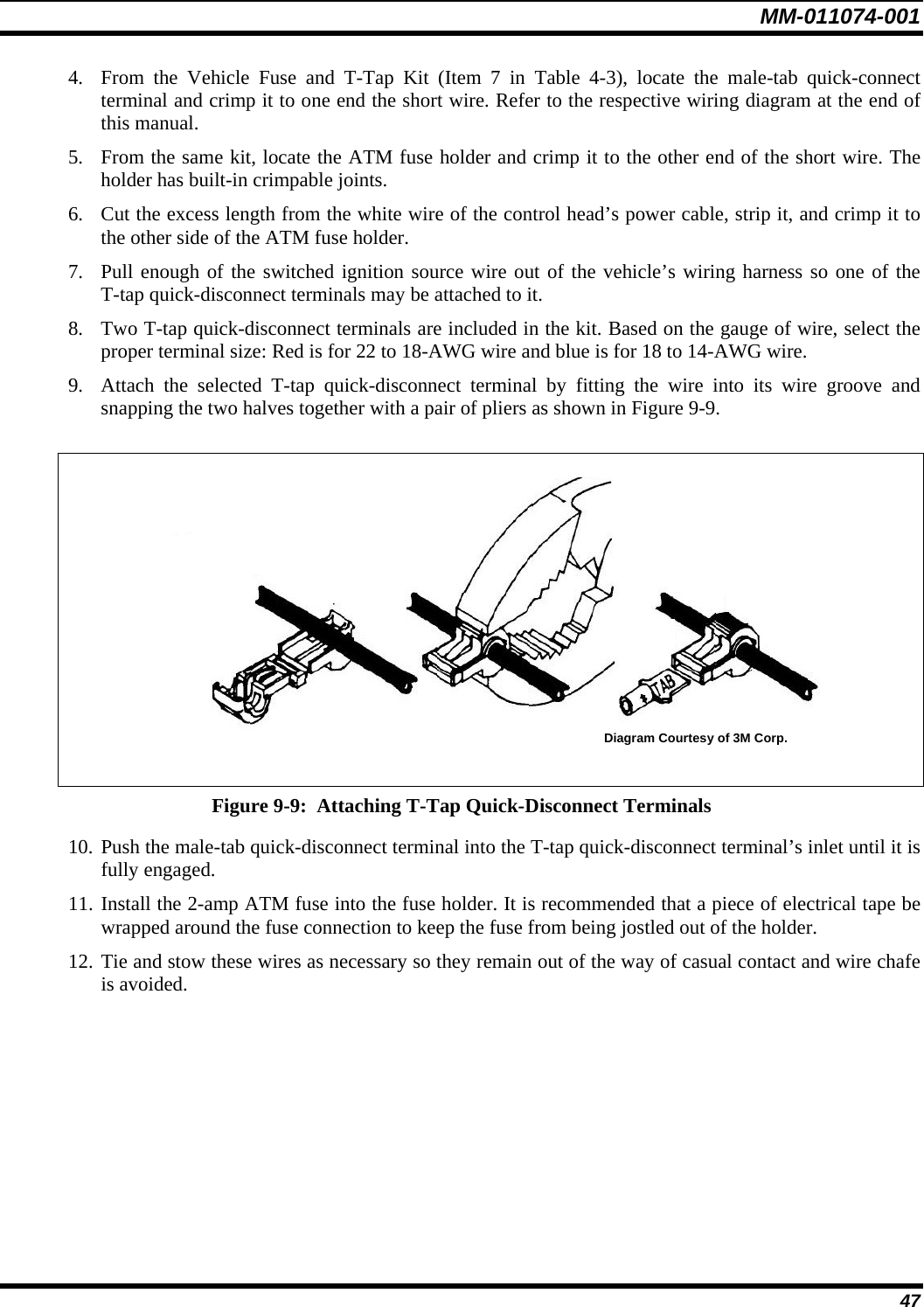
Upload a User Manual
Namespaces
Wiki Guide
HTML
PDF
Info
Views
User Manual
Discussion / Help
Navigation

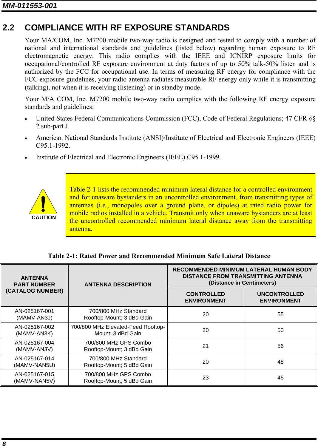
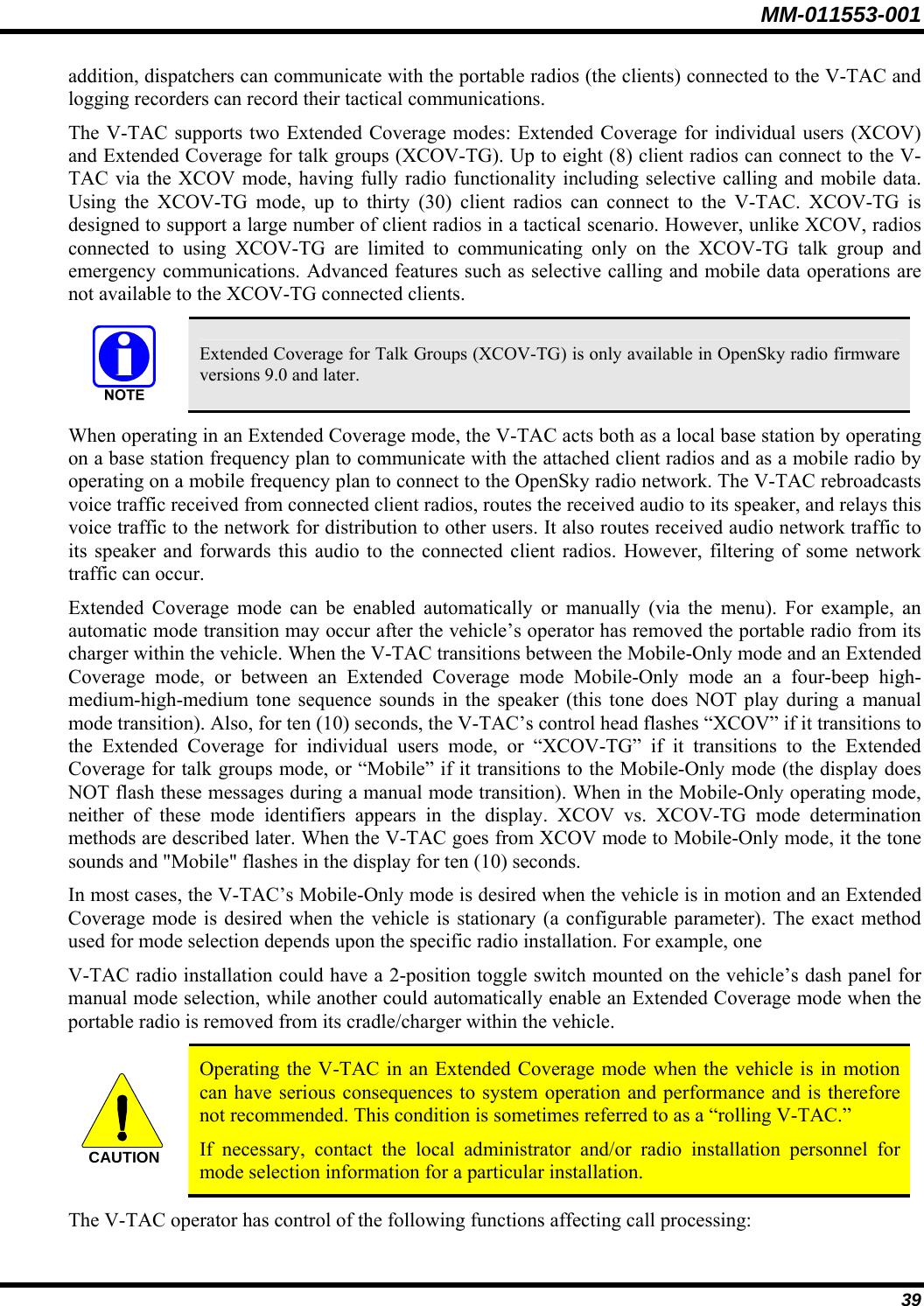
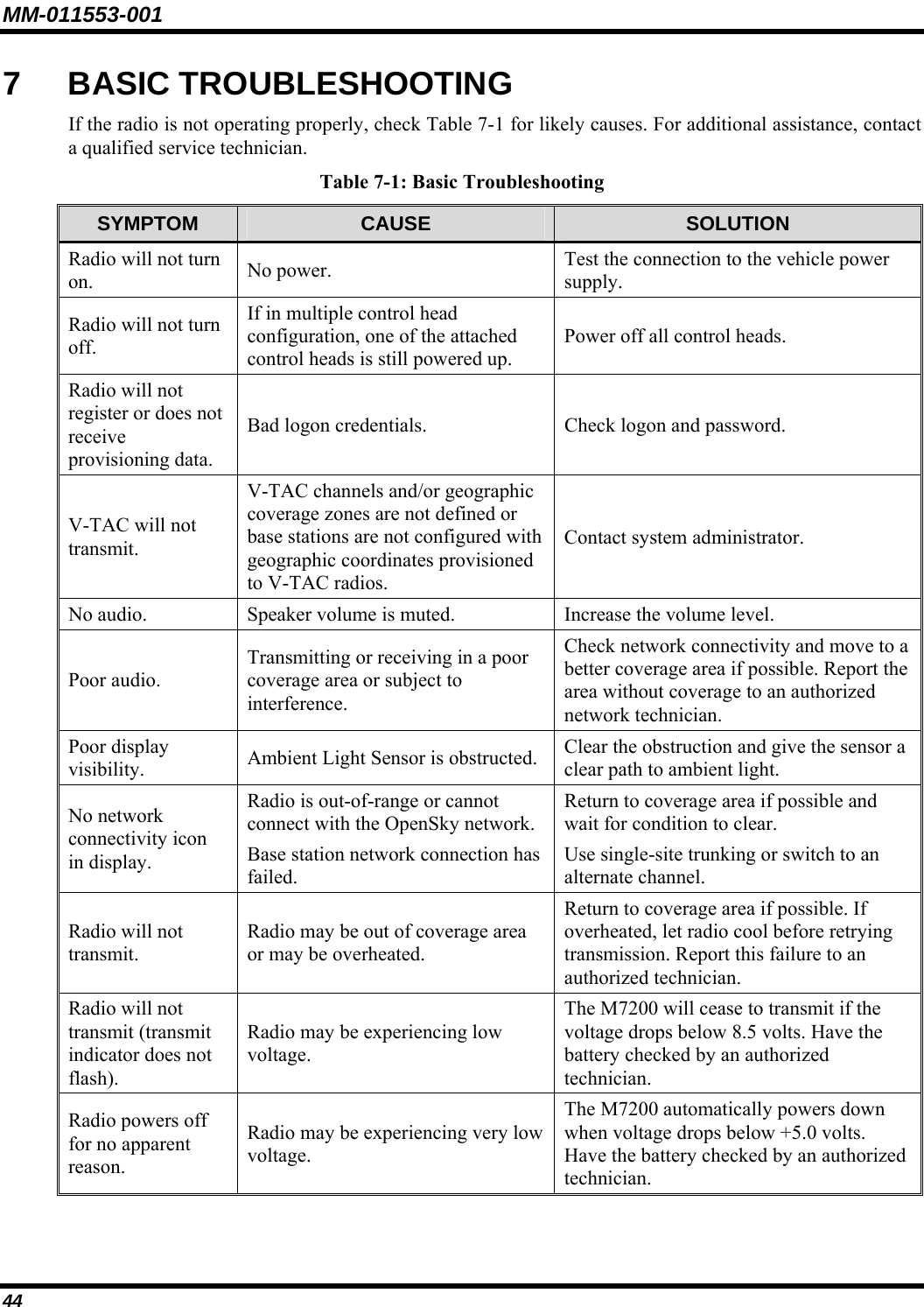
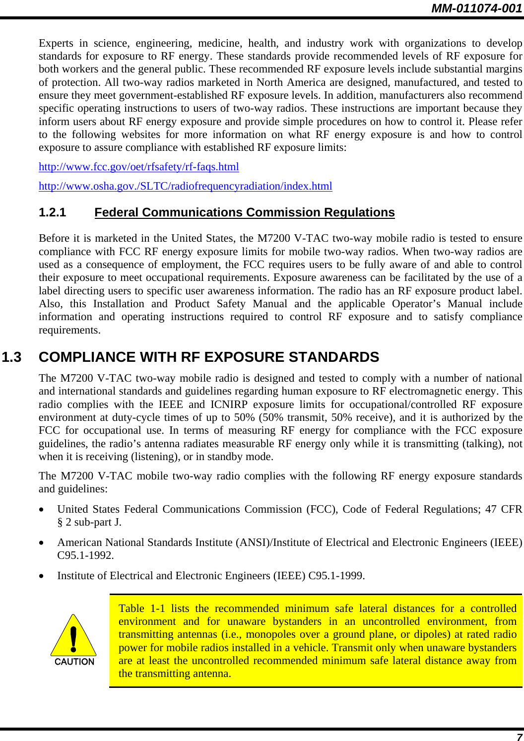
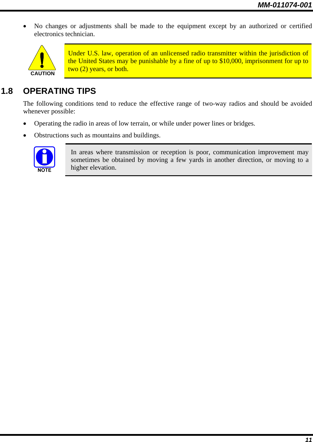
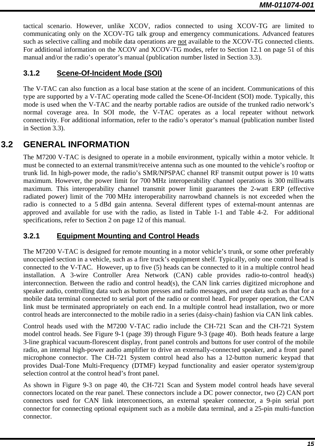
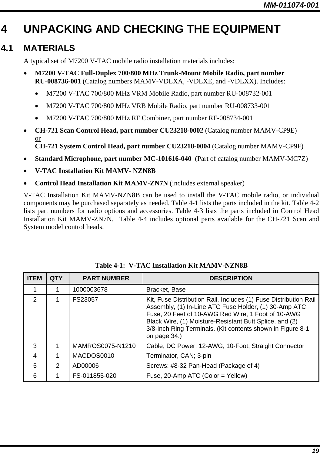
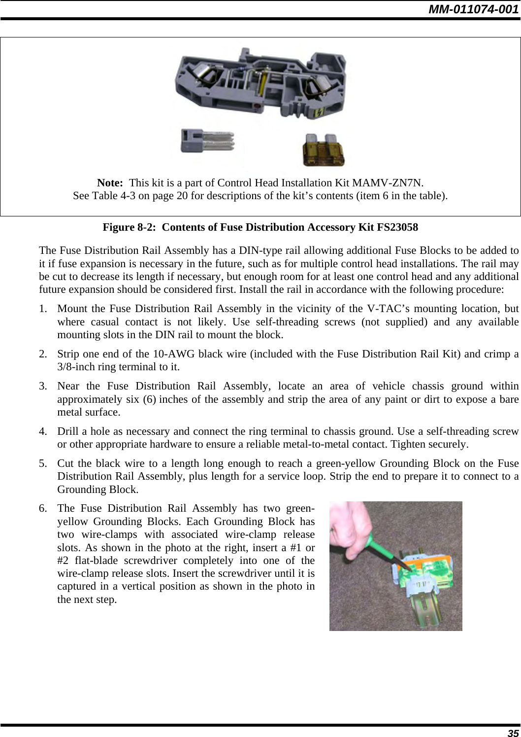
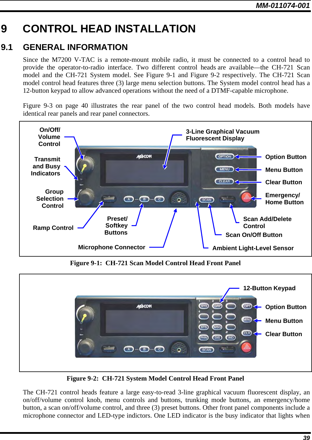
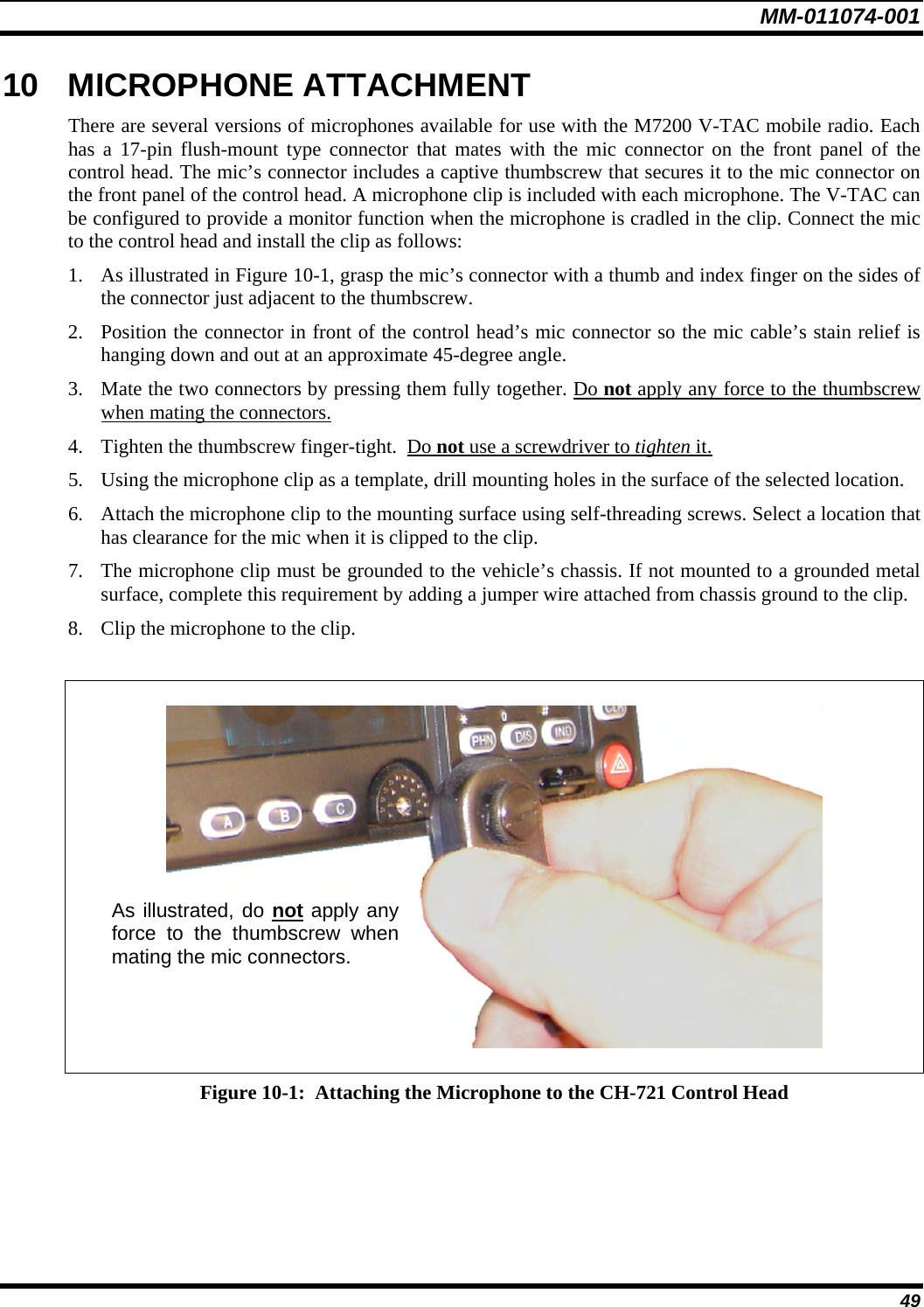
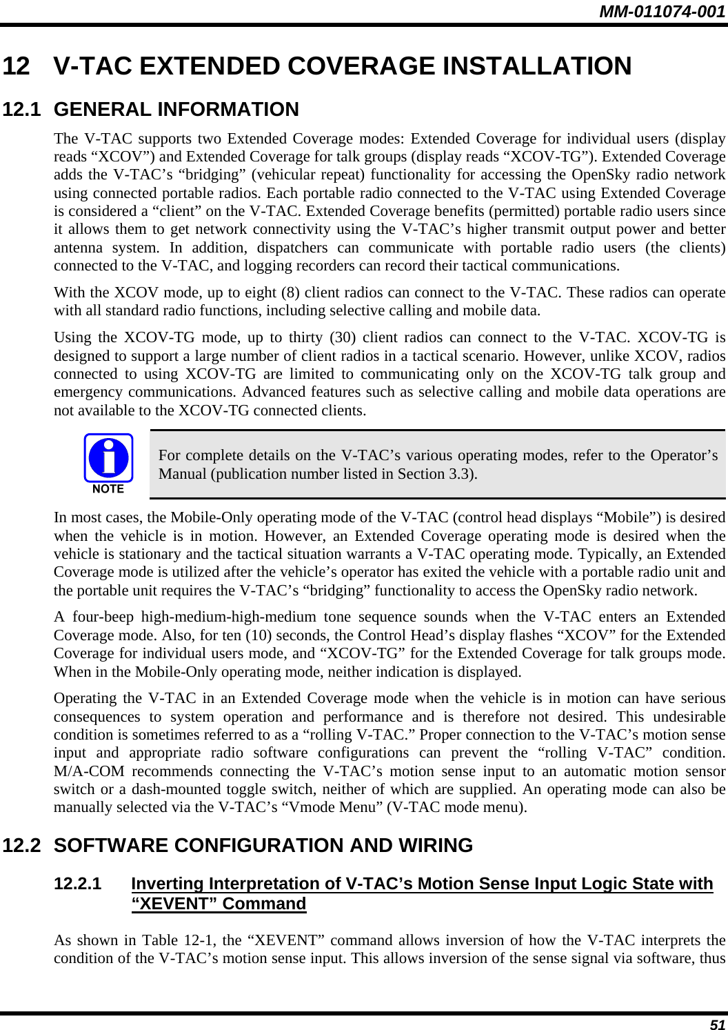
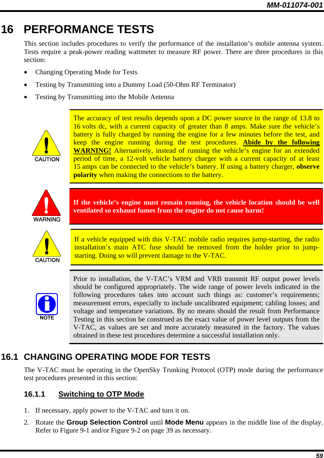
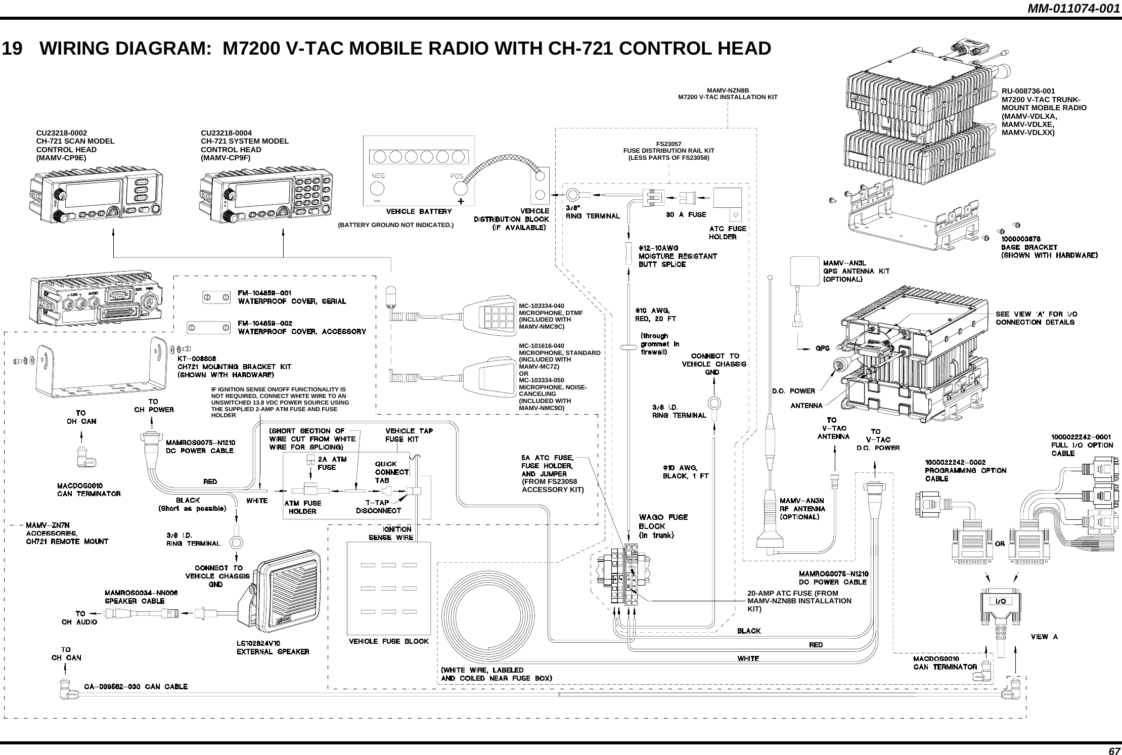
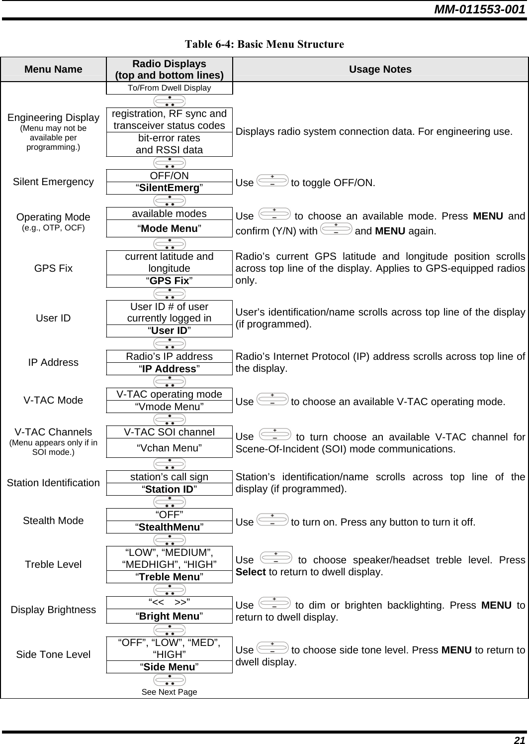
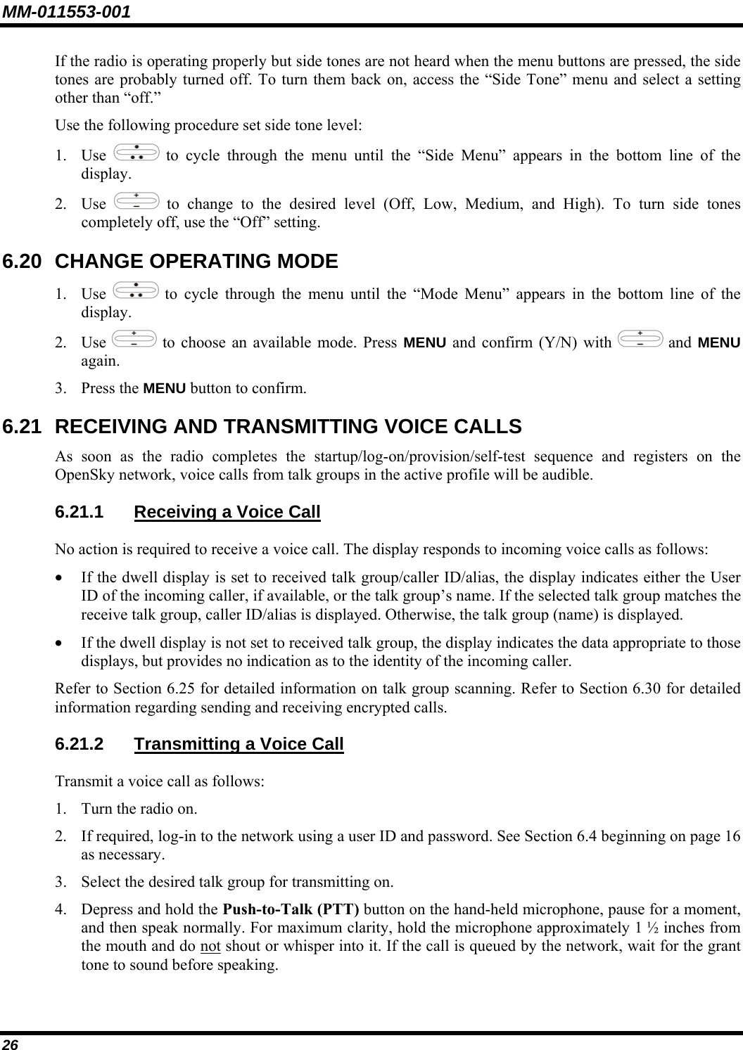
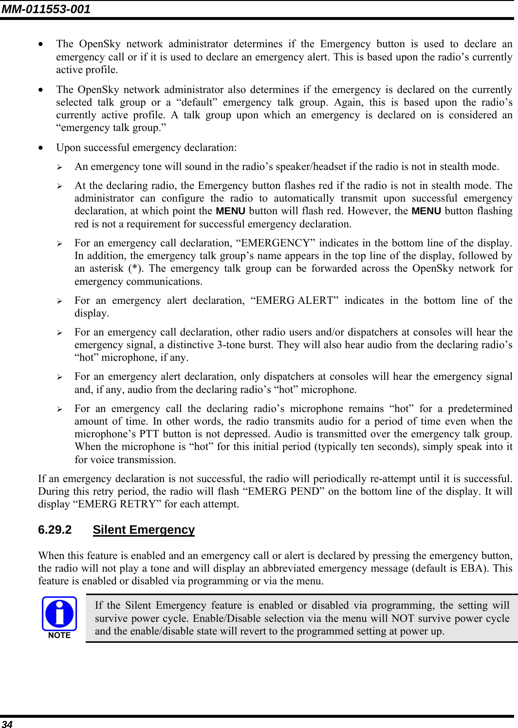
![MM-011553-001 6.2 POWER UP AND VOLUME CONTROL 6.2.1 Power Up 1. Rotate the Power/Volume Control knob clockwise to power on the radio. The display will illuminate when the radio powers up. 2. Wait for the power-up sequence to complete, which takes approximately ten (10) seconds. During this time, if enabled for auto registration, the radio is provisioned with a customized user personality designed for the user’s specific needs by the OpenSky network administrator. If this personality contains encrypted talk groups or if the user is authorized for, and intends to use, manual encryption, User Login must be performed. This requires a system model control head so that the User ID and password can be entered. 3. When provisioning is complete, the radio will display the Dwell Display. If User Login is required, the bottom line of the Dwell Display will flash the message “Pls Login.” 6.2.2 Volume Control Turn the Power/Volume Control knob clockwise to increase the volume and counter-clockwise to decrease the volume. 6.3 SELF-TEST After power-up, the M7200 radio undergoes a multi-function automatic registration procedure. As many as sixteen (16) possible radio profiles are downloaded to the radio from the network in response to the User’s ID. 6.4 LOGIN TO THE NETWORK Login occurs either automatically (auto registration) if the radio has a valid registration or, if enabled and authorized for encryption (Section 6.30), requires the user to enter a User ID and password. If encryption is enabled and authorized on the radio, the user will be prompted to “Pls Login” with the *1 login command, a User ID, and password [System Model Control Head required]. 1. Press *1 (Login command). 2. Enter the full 10-digit User ID. 3. Press the # key. 4. Enter the password. See the following NOTE. • If the radio is configured for alpha-numeric passwords and the password has consecutive duplicate numbers (“MES33” for example), enter # between the consecutive duplicate numbers so the radio will not interpret the entry as a letter (“D” in this example). • If the radio is configured for numeric-only passwords, do not enter # between duplicated numbers. 5. Press the # key twice. 16](https://usermanual.wiki/HARRIS/M7200VTAC/User-Guide-766993-Page-17.png)
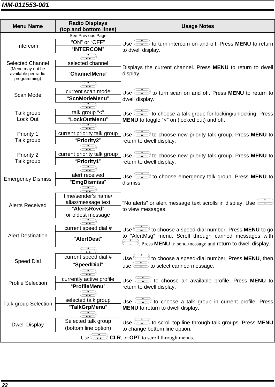
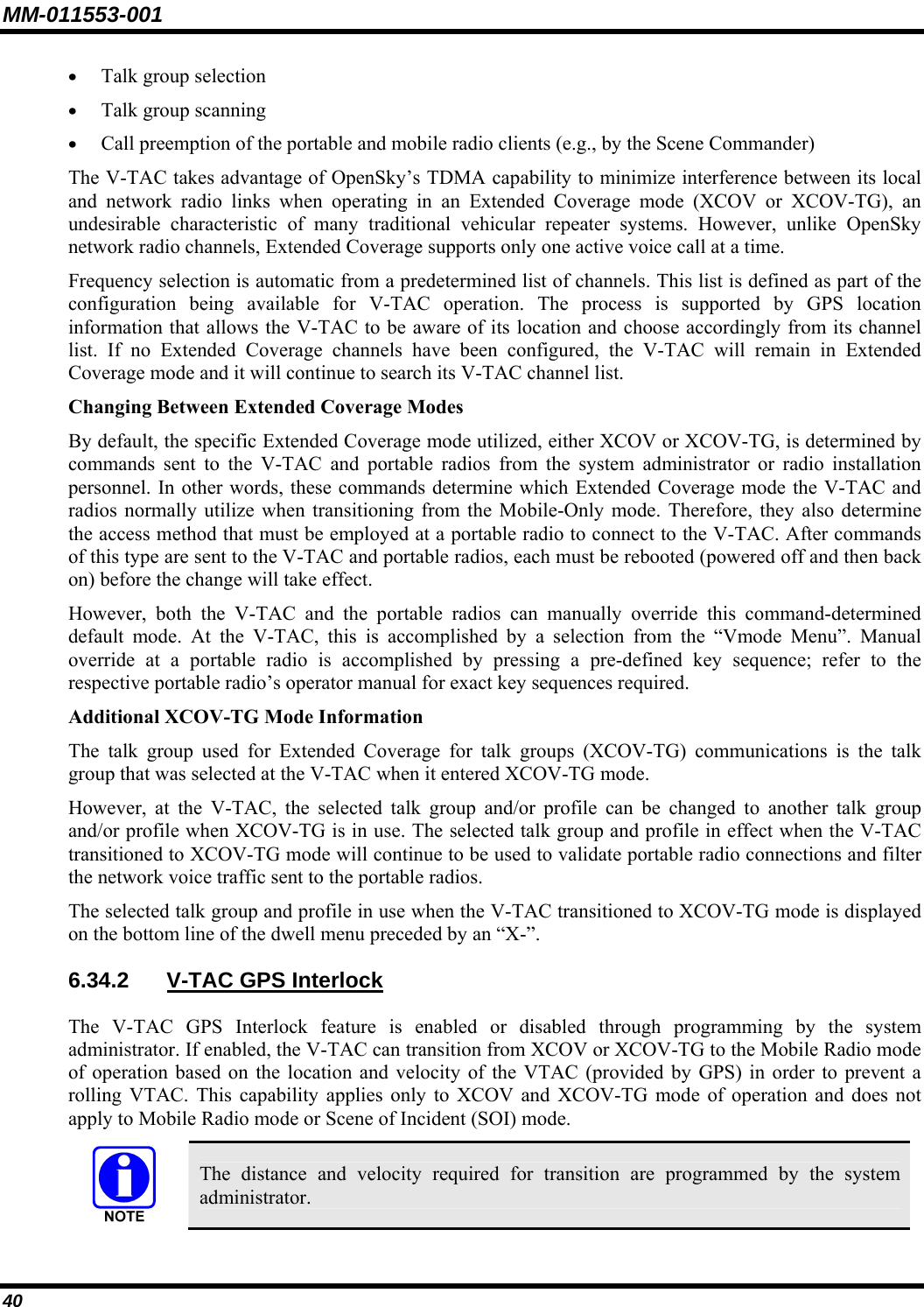
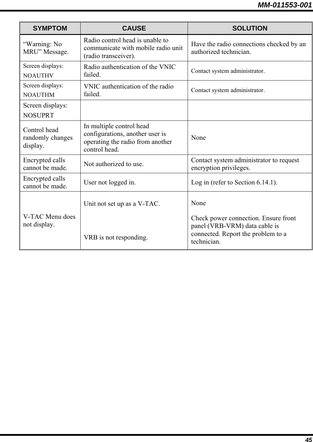
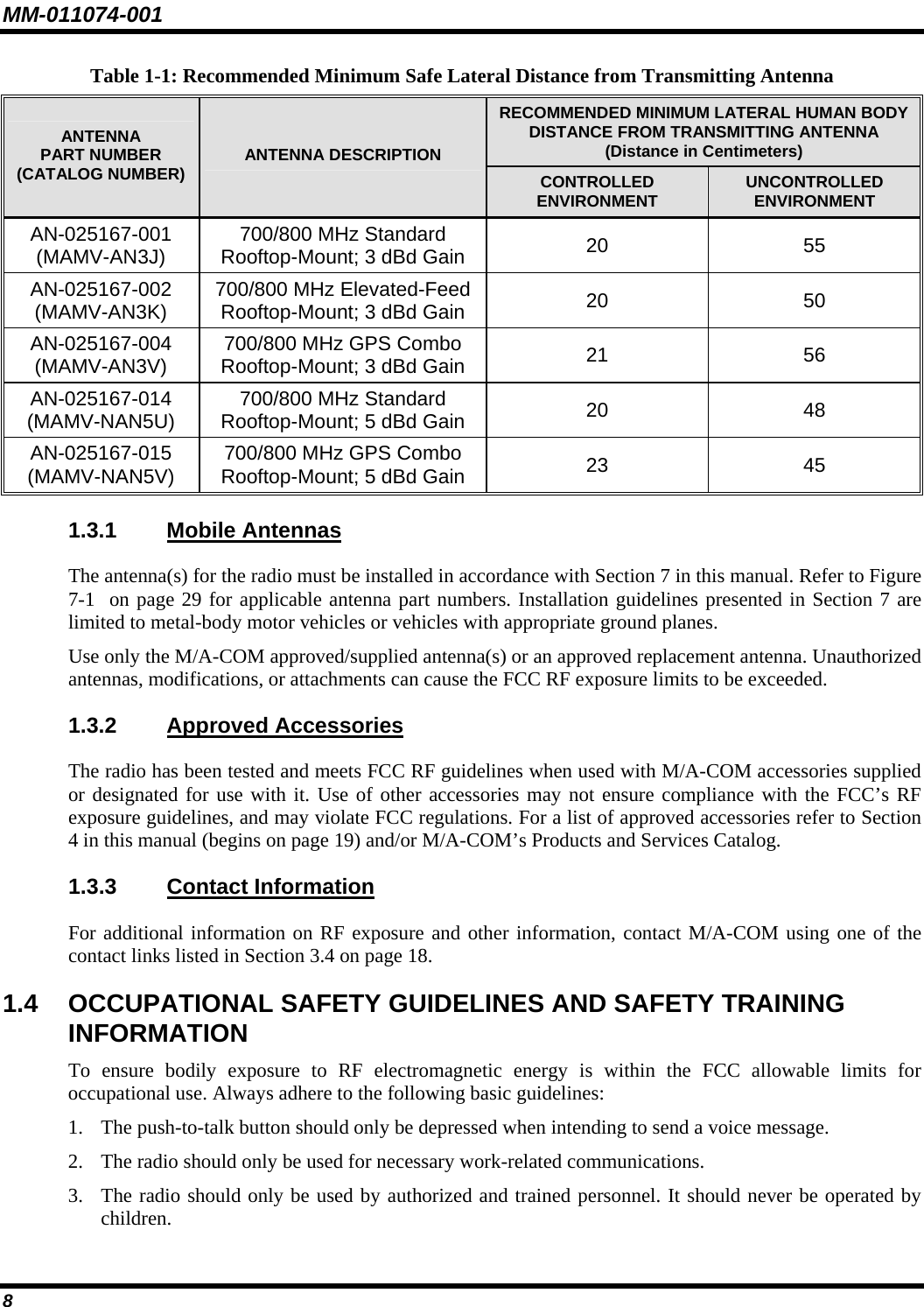
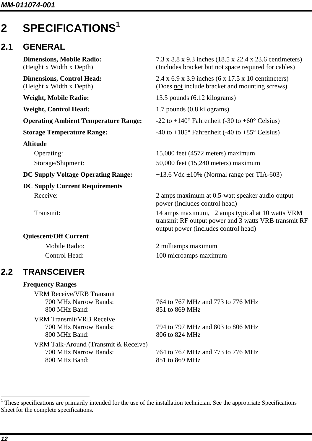
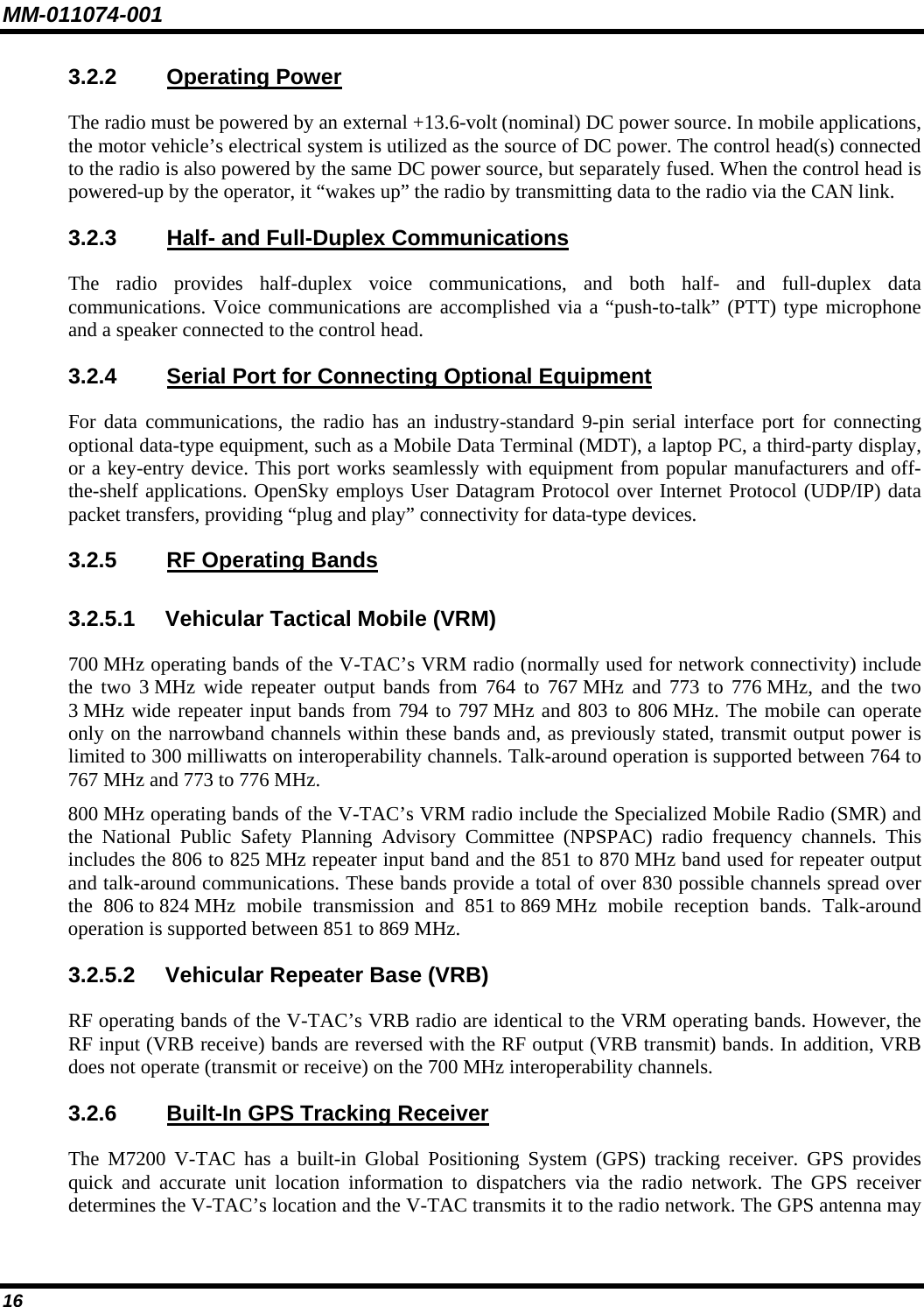
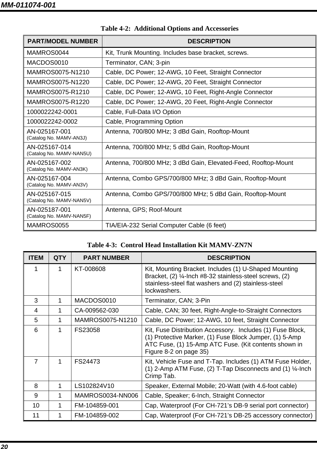
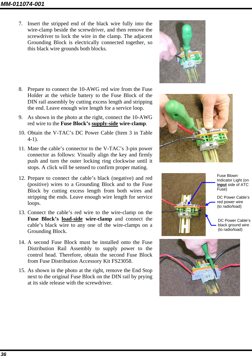
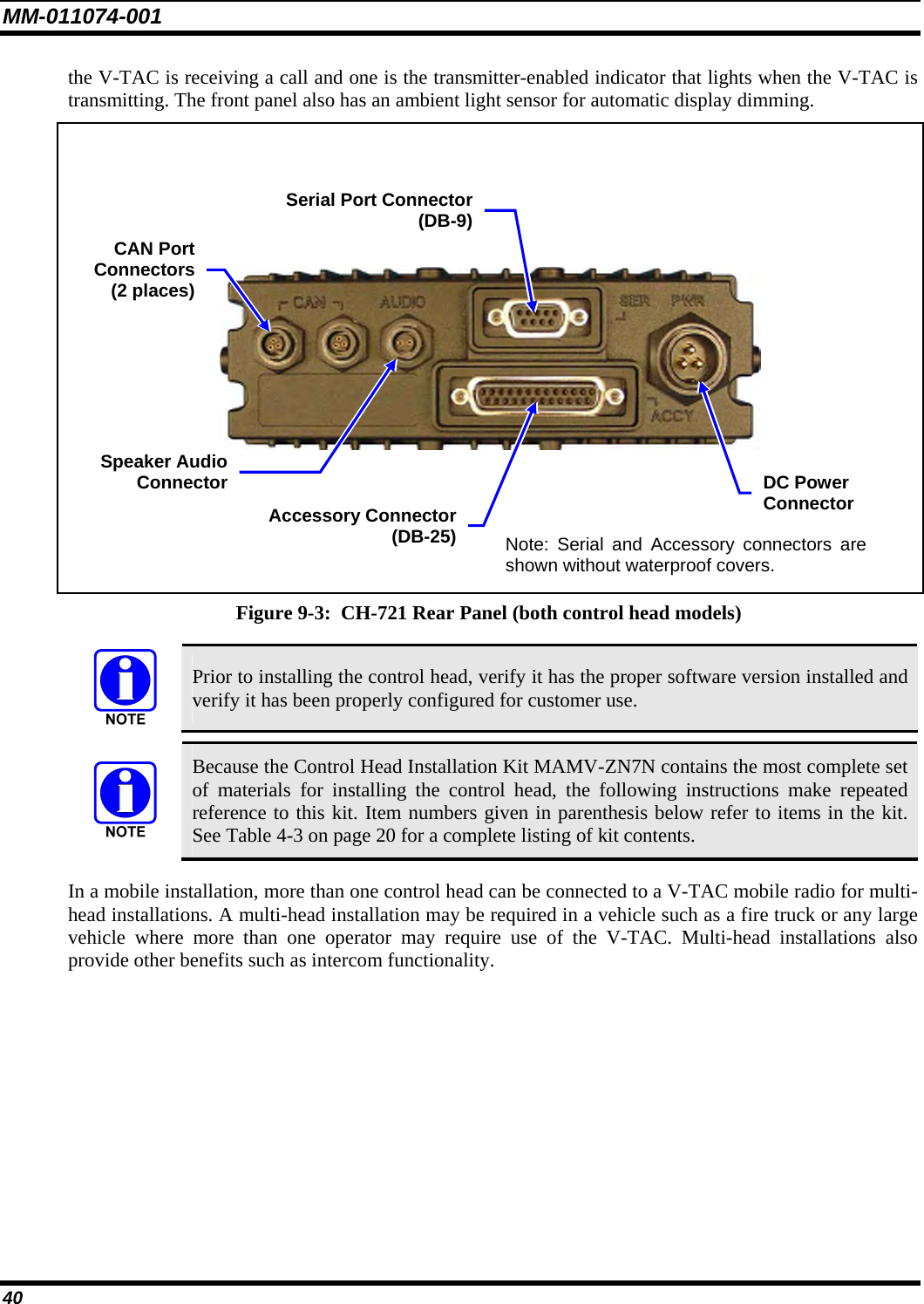
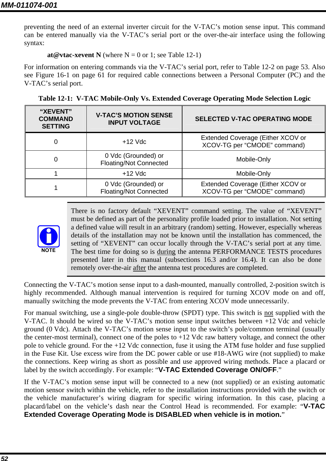
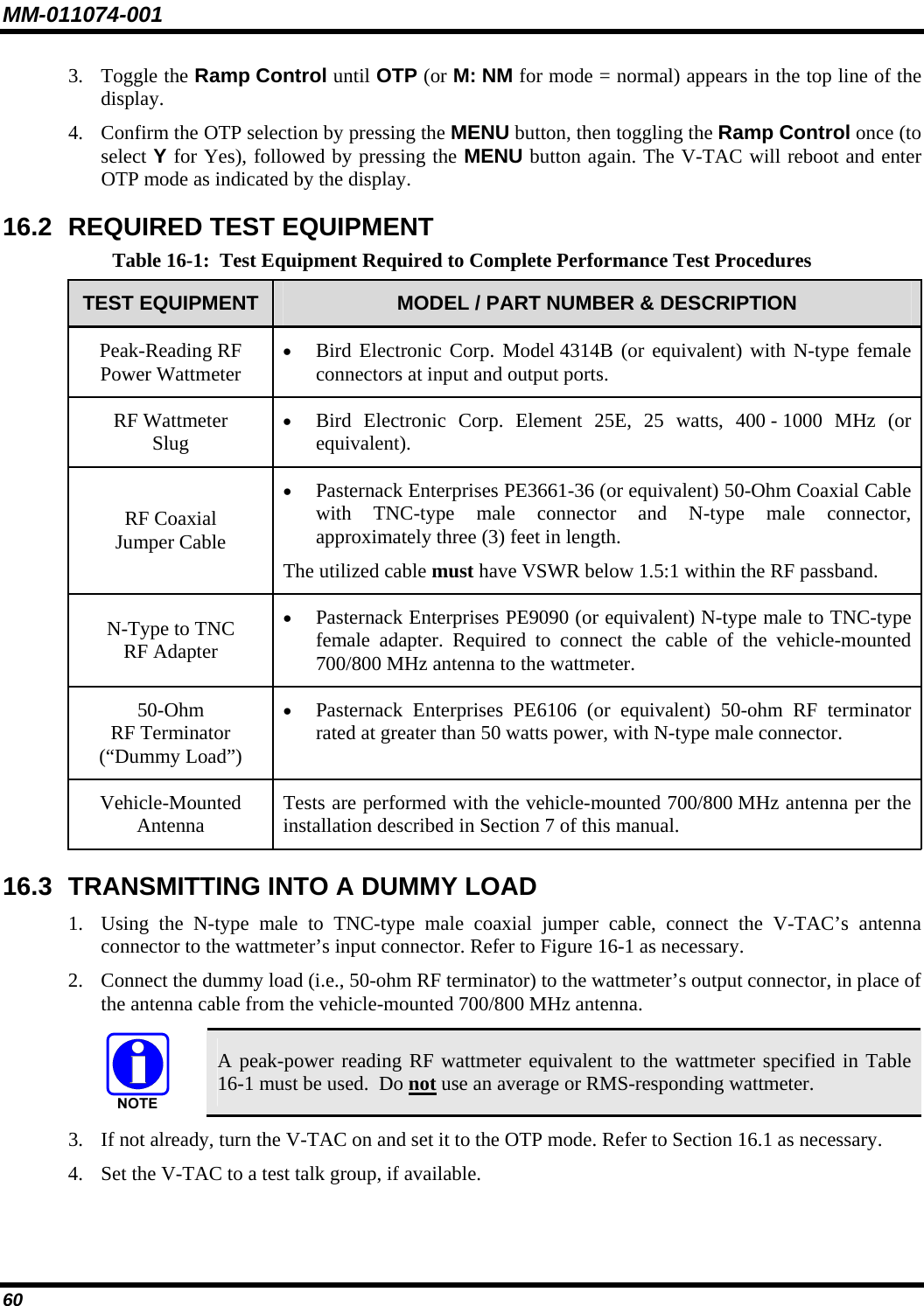
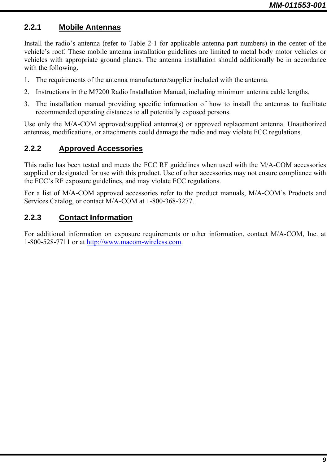
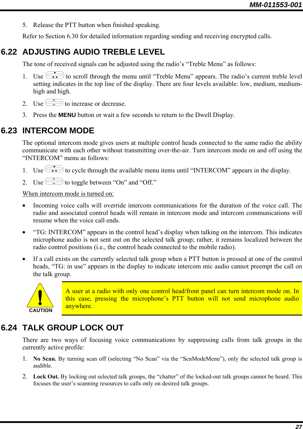
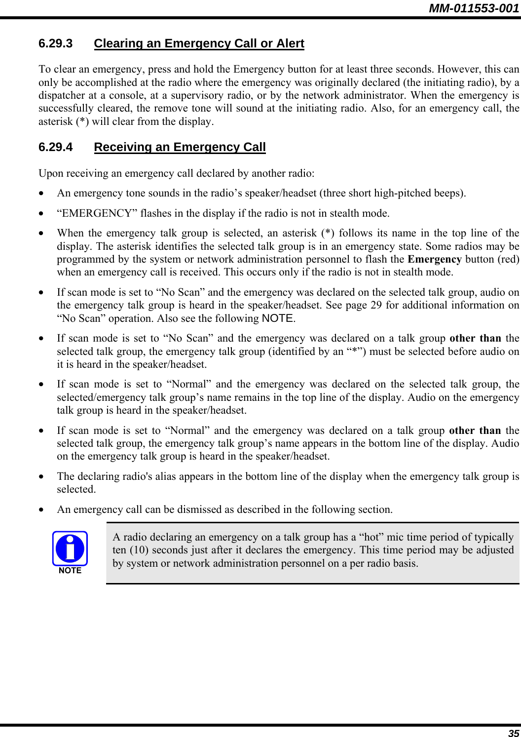
![MM-011553-001 Menus and button function will vary depending upon system programming, radio hardware, and optional configurations. No V-TAC-related menus are displayed on non-V-TAC radios/control heads. The “Vchan Menu” is only displayed if the V-TAC is in the SOI mode. If a V-TAC is in an Extended Coverage mode (XCOV or XCOV-TG), the number of portable radios (“clients”) connected to the V-TAC is displayed in the bottom line of the dwell menu. If a V-TAC is in the Extended Coverage for talk groups mode (XCOV-TG), the selected talk group and profile in use is displayed. 6.13 DUAL-TONE MULTI-FREQUENCY Dual-Tone Multi-Frequency (DTMF) is the system used by touch-tone telephones. DTMF assigns a specific tone frequency to each key so a microprocessor can easily identify its activation. The radio supports DTMF with a system model control head (Figure 6-1). This allows for specific tasks such as entering a user ID and password, or selective calling. When a key on the DTMF keypad is pressed, a single low-pitched tone will be heard from the microphone. The key tones are not adjustable. 6.14 KEYPAD COMMANDS (SYSTEM MODEL CONTROL HEAD) To perform a command from the keypad, press the * key followed by one of the pre-set function keys as follows: Table 6-5: Keypad Function Commands *0 Log-off command: *0## (logs the user off the system). See page 17 for additional information. Log-in command: *1<User ID> # <Password> ## (required for encryption). See page 16 for additional information. *1 *4 Enter Scene of Incident Mode (SOI) on specified channel. Exit SOI Mode with *4#. Initiate Selective Alert command: *7<Target ID>#[Choose Message]#. See page 31 for additional information. *7 Radio-to-Radio Call command: Selective call number # (PTT to dial). *8 Public Switched Telephone Network (PSTN) Call command: See page 33 for additional information. *9 Begin Manual Encryption command: *32<Pre-Determined Encryption Key of Up To 16 Digits># See page 36 for additional information. *32 End Manual Encryption command. *33 Initiate XCOV Mode: Extended coverage for individual users. *61 Initiate XCOV-TG Mode: Extended coverage for talk groups. *62 *60 Exit XCOV or XCOV-TG Mode: Returns to the normal mode. 23](https://usermanual.wiki/HARRIS/M7200VTAC/User-Guide-766993-Page-24.png)
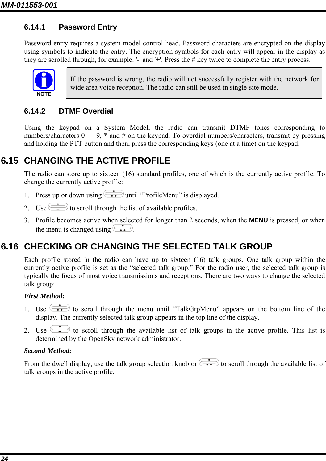
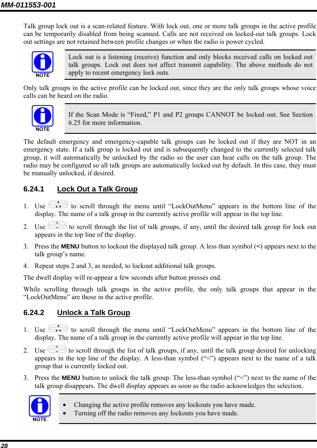
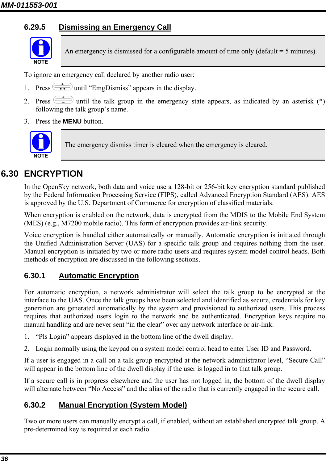
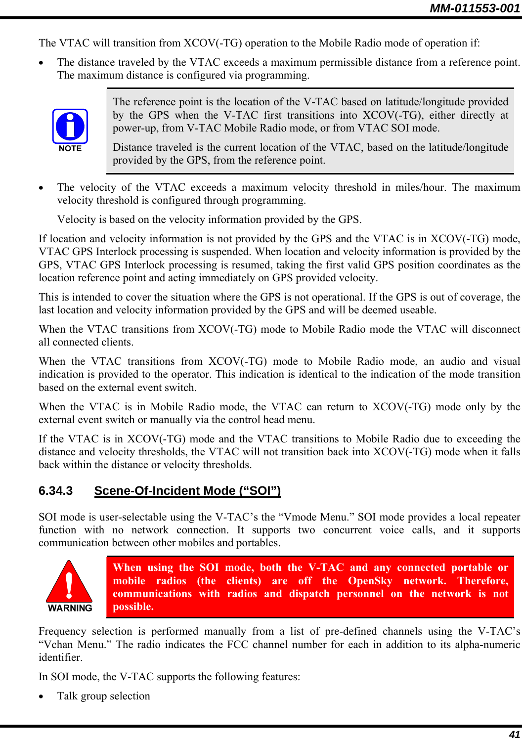
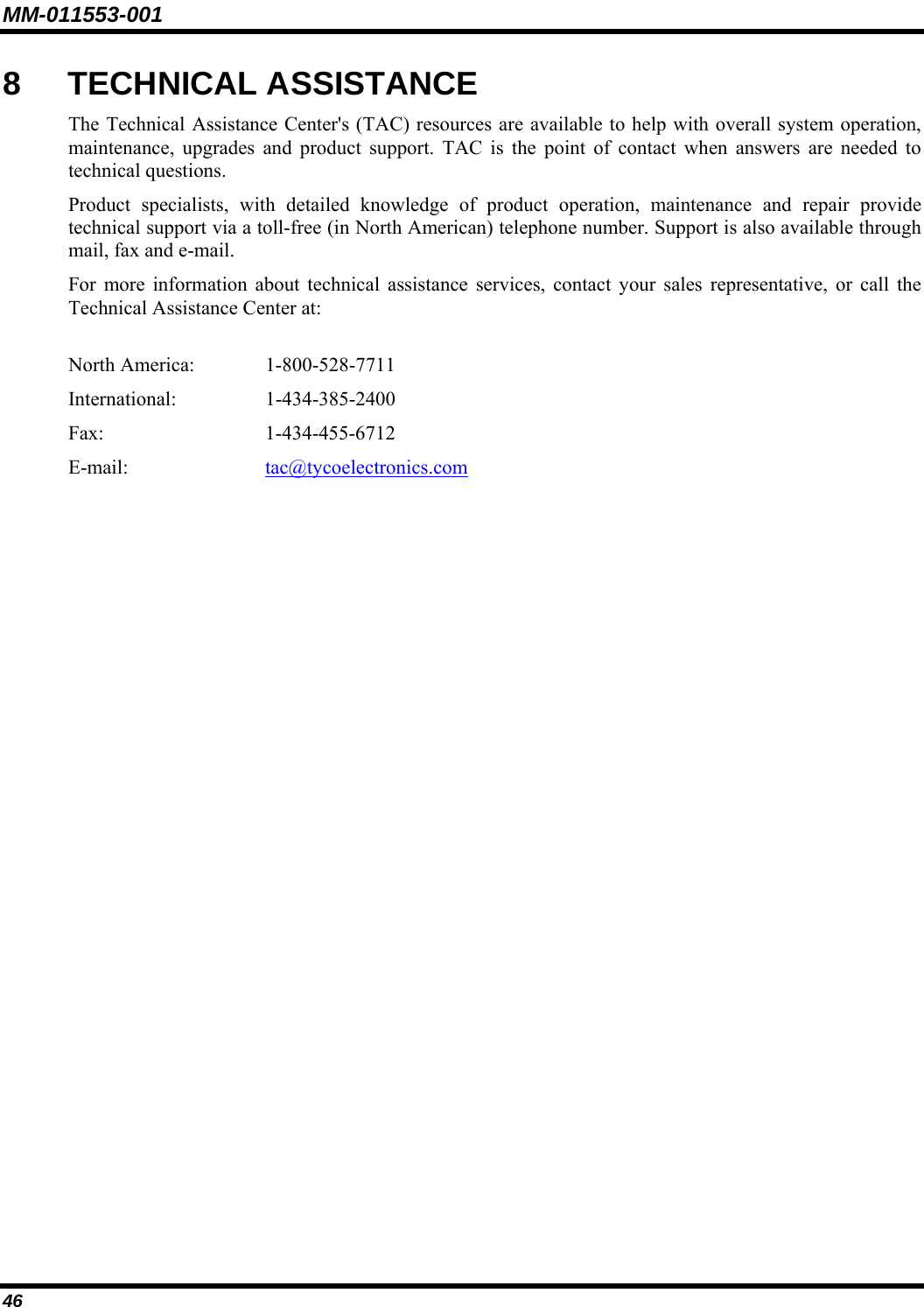
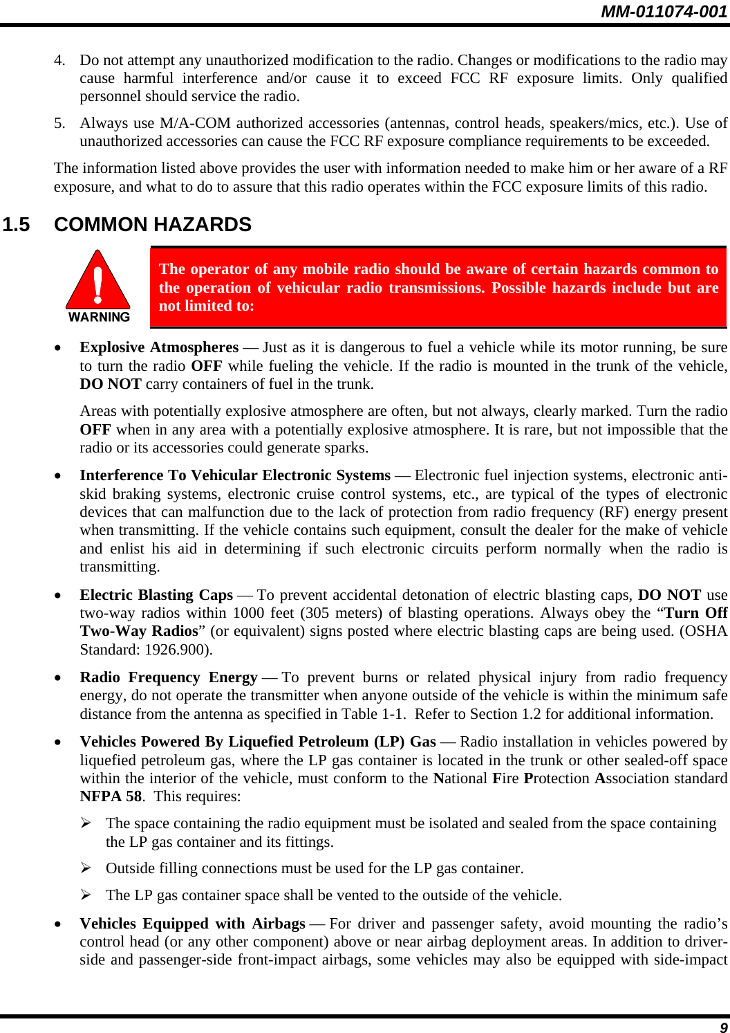
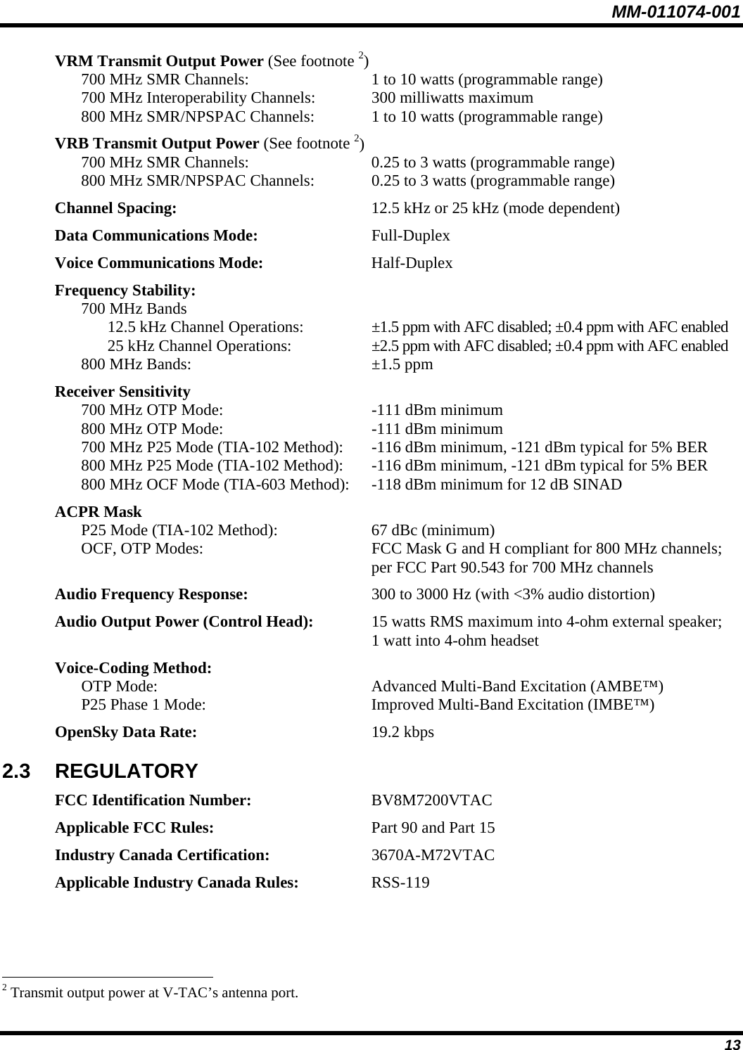
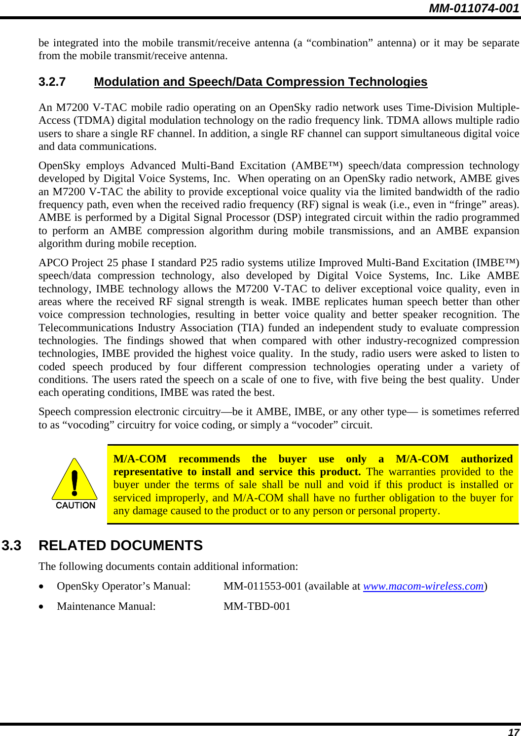
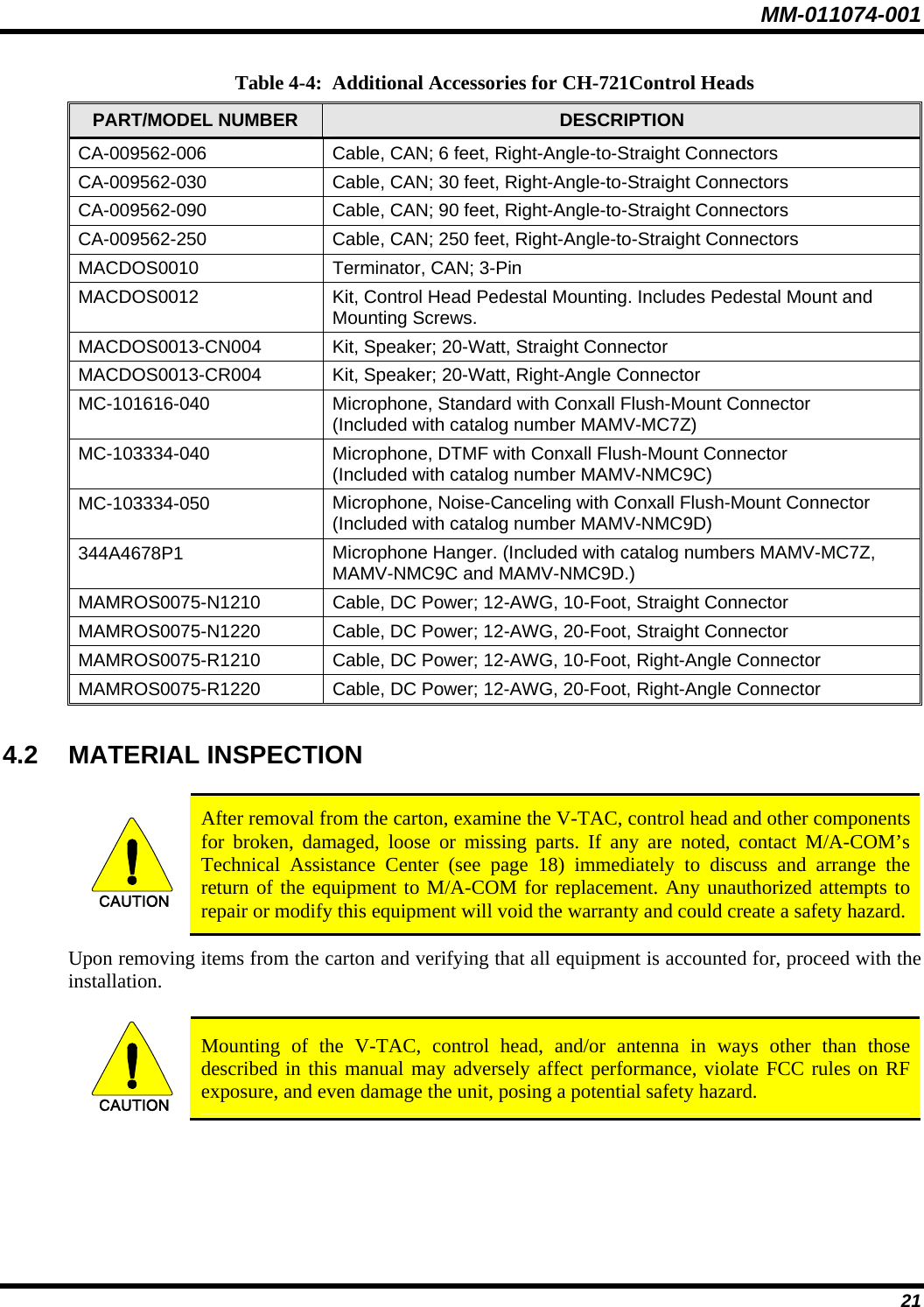
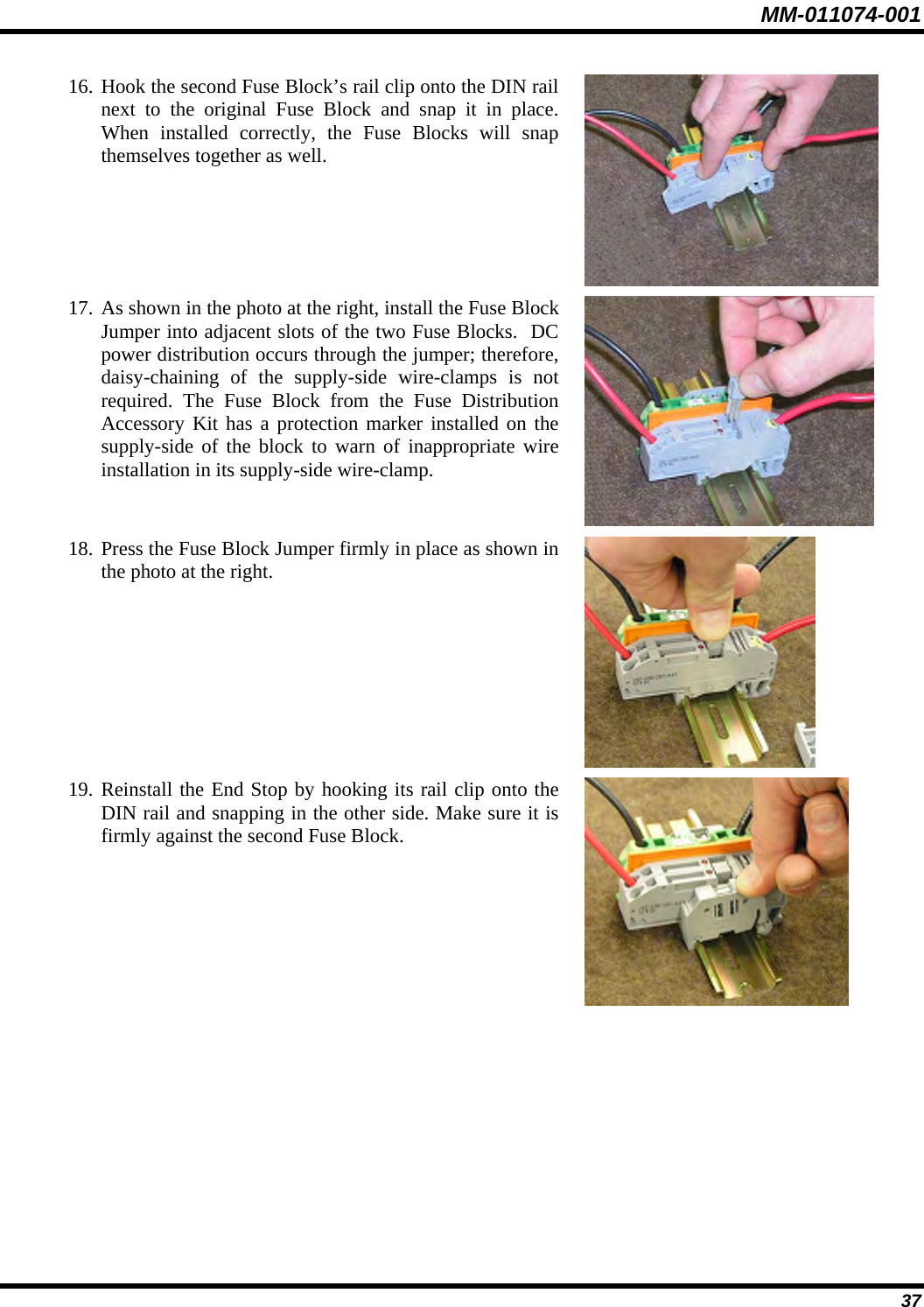
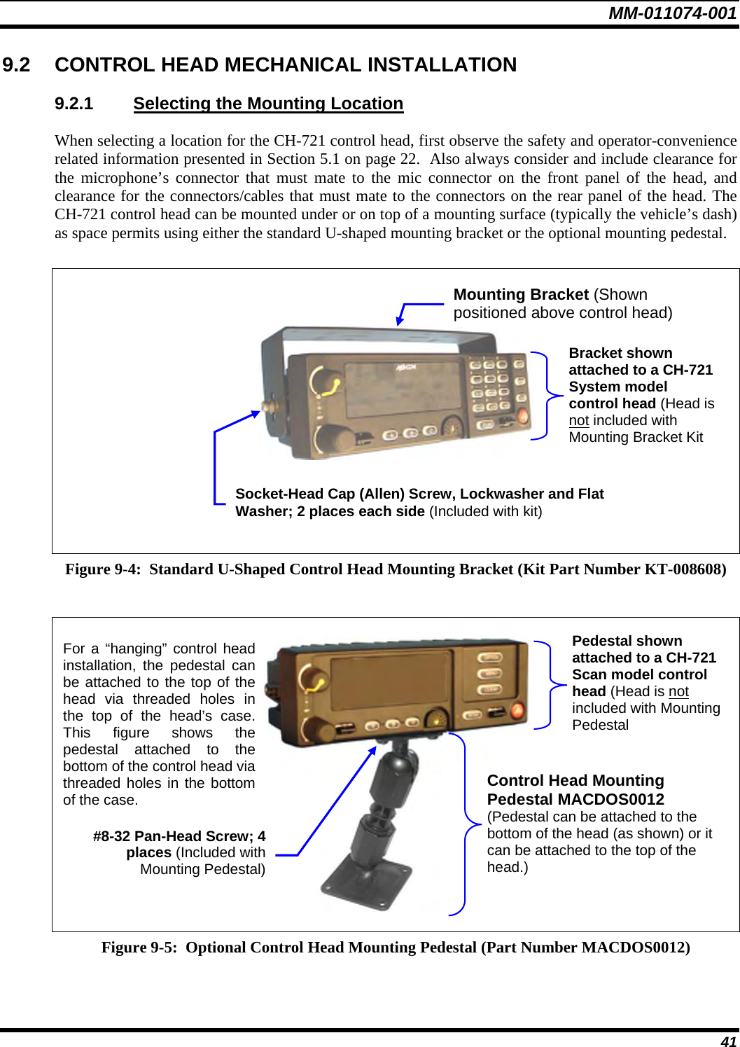
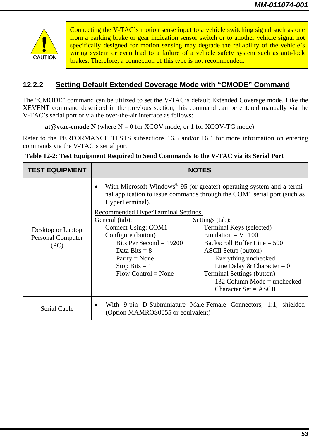
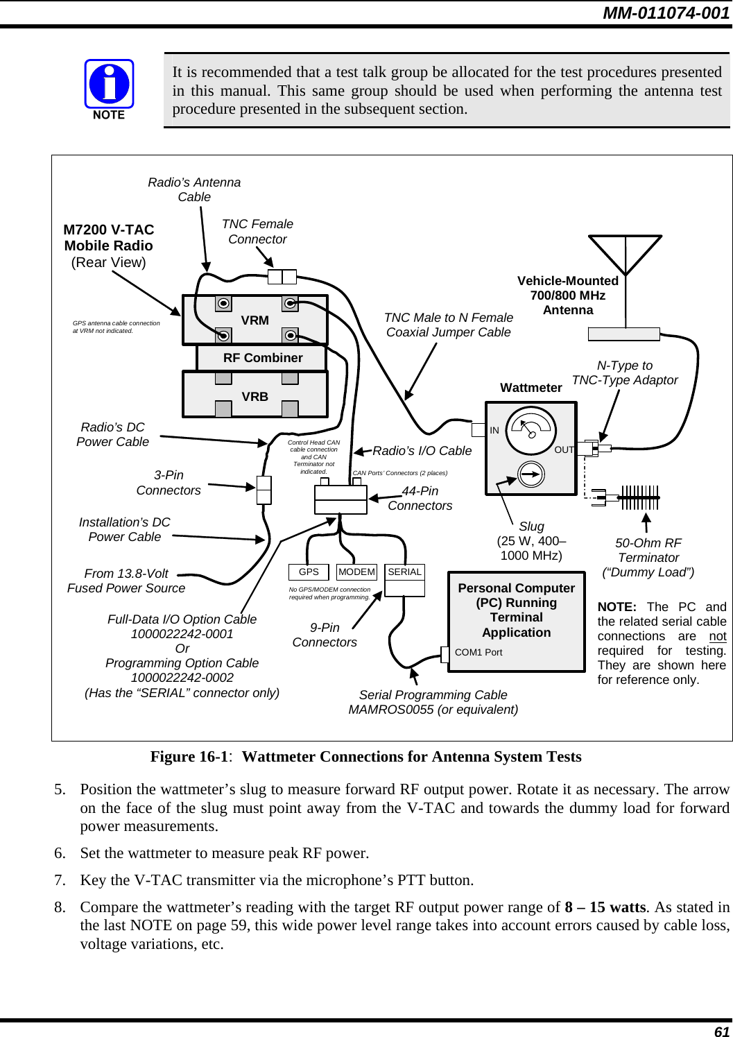
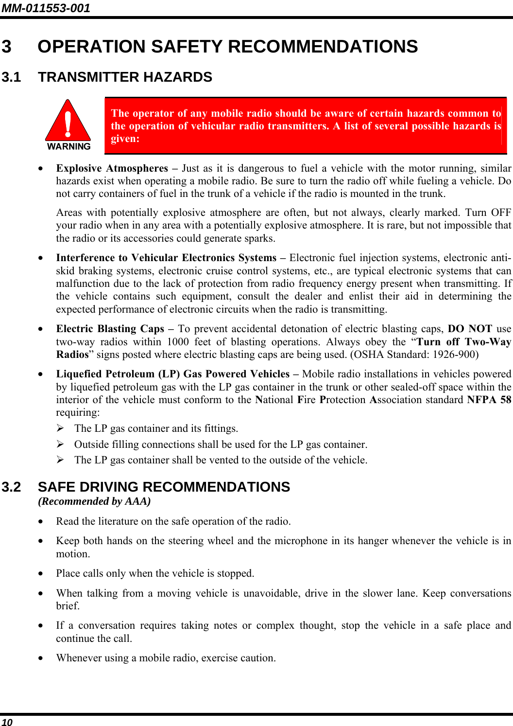
![MM-011553-001 6.32 DYNAMIC REGROUPING Dynamic regrouping requires that the network administrator determine which radio users should be formed into an impromptu talk group to respond to particular emergency conditions. The administrator will edit the personalities of the affected radios to include an emergency profile and then page the affected radios to re-register with the network to receive their edited personalities. In response, affected radios automatically re-register to receive their edited personalities. During re-registration, subscriber equipment will default to the emergency profile selected by the administrator. 6.33 GPS COORDINATES The radio’s current latitude and longitude coordinates may be displayed using the “GPS” menu. The following procedure assumes a GPS antenna is connected to the radio and it is receiving adequate signals from GPS satellites: 1. Press until the “GPS” menu appears in the bottom line of the display. Current GPS coordinate latitude and longitude data continuously scrolls in the top line of the display in a degrees:minutes:seconds format. 2. Use to change to another menu. If the internal GPS receiver’s data is expired (30 minutes or more) or unavailable, the radio uses the serving base station’s coordinates [GPS (Site) is displayed]. The GPS Menu will also indicate if the data is aged (2 minutes or more) [GPS (Aged) is displayed] 6.34 V-TAC FUNCTIONS When a mobile radio detects that it is part of a V-TAC configuration, two additional menu items become available: “Vmode Menu” and “Vchan Menu.” The “Vchan Menu” is available only when a V-TAC is operating in the special mode referred to as the Scene-of-Incident mode (SOI). The “Vmode Menu” permits user selection and control of one of four (4) different V-TAC operating modes: • Extended Coverage for Individual Users (display reads “XCOV”) • Extended Coverage for Talk groups (display reads “XCOV-TG”) • Scene-of-Incident (display reads: “SOI”) • Mobile-Only (display reads: “Mobile”) These modes are described in detail in the following subsections. 6.34.1 Extended Coverage Modes (“XCOV” & “XCOV-TG”) General Information In addition to all standard mobile radio operating capabilities, Extended Coverage adds the V-TAC’s bridging (vehicular repeat) functionality for accessing the OpenSky radio network using connected portable radios. Each portable radio connected to the V-TAC using Extended Coverage is considered a “client” on the V-TAC. Extended Coverage benefits (permitted) portable radios since it allows them to get network connectivity using the V-TAC’s higher transmit output power and better antenna system. In 38](https://usermanual.wiki/HARRIS/M7200VTAC/User-Guide-766993-Page-39.png)