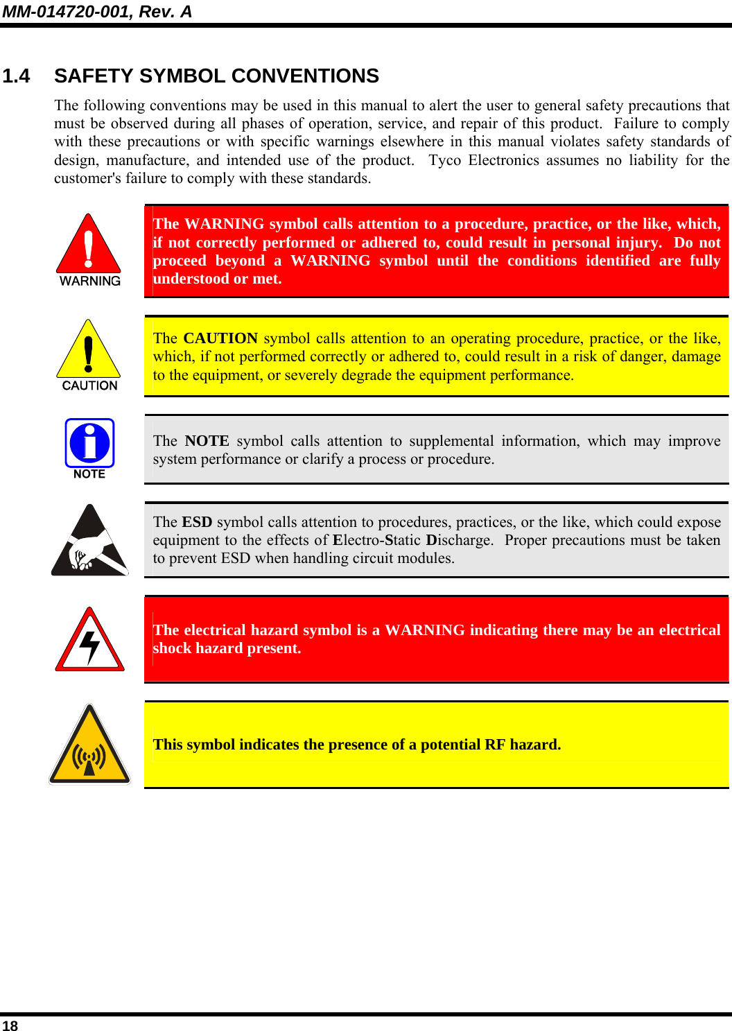
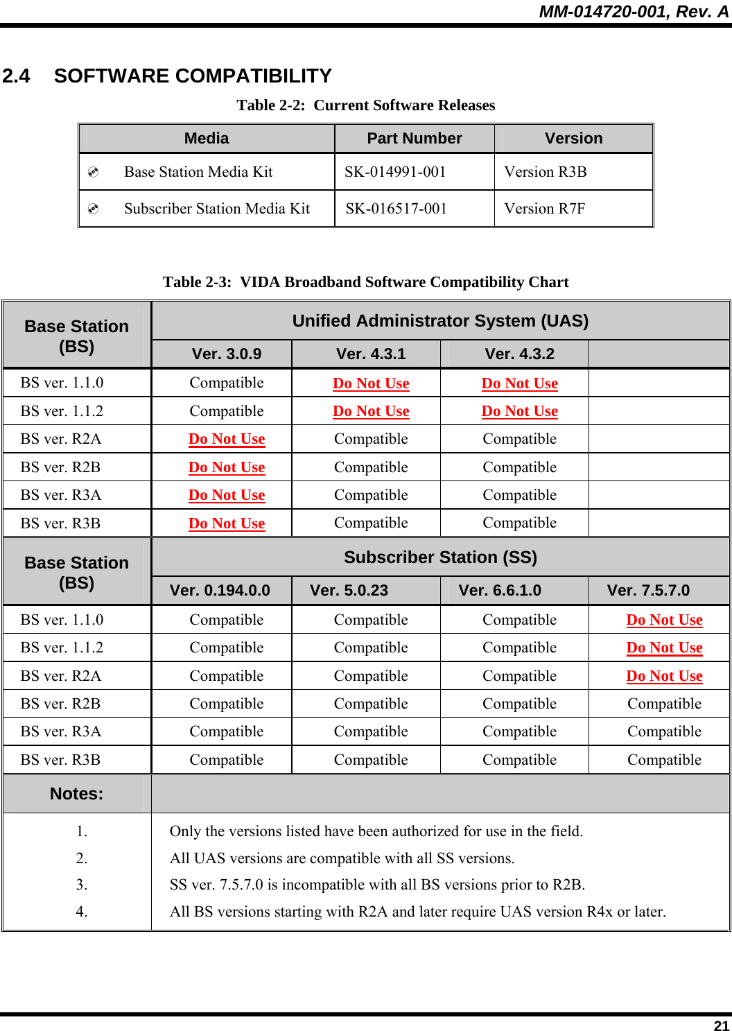
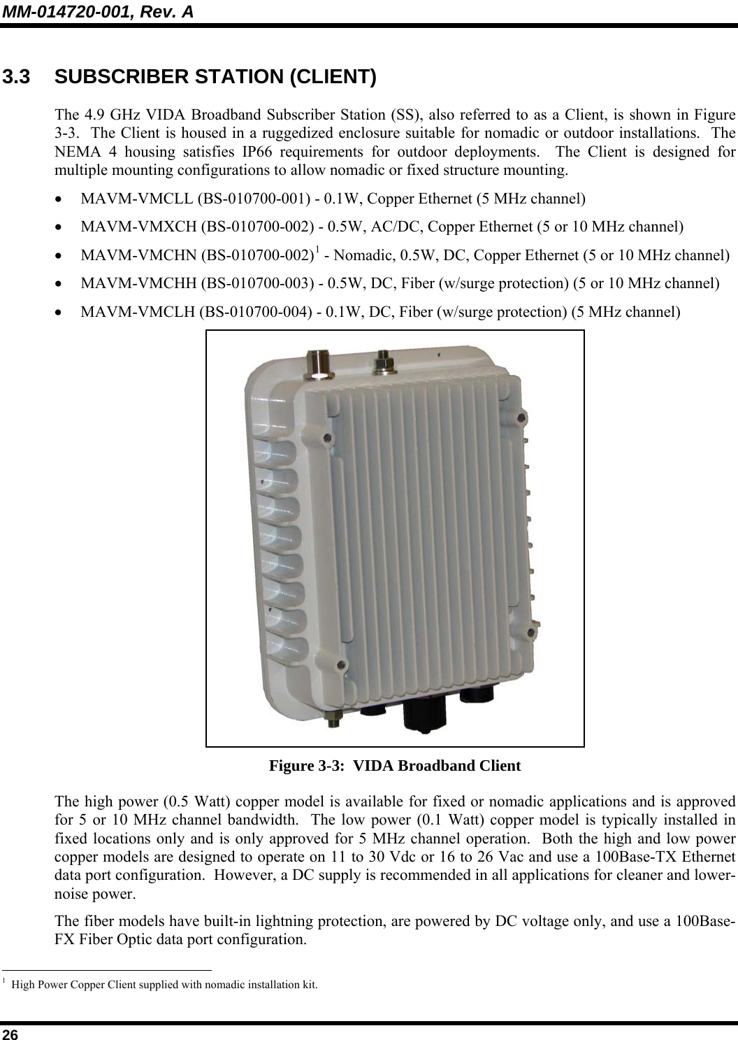
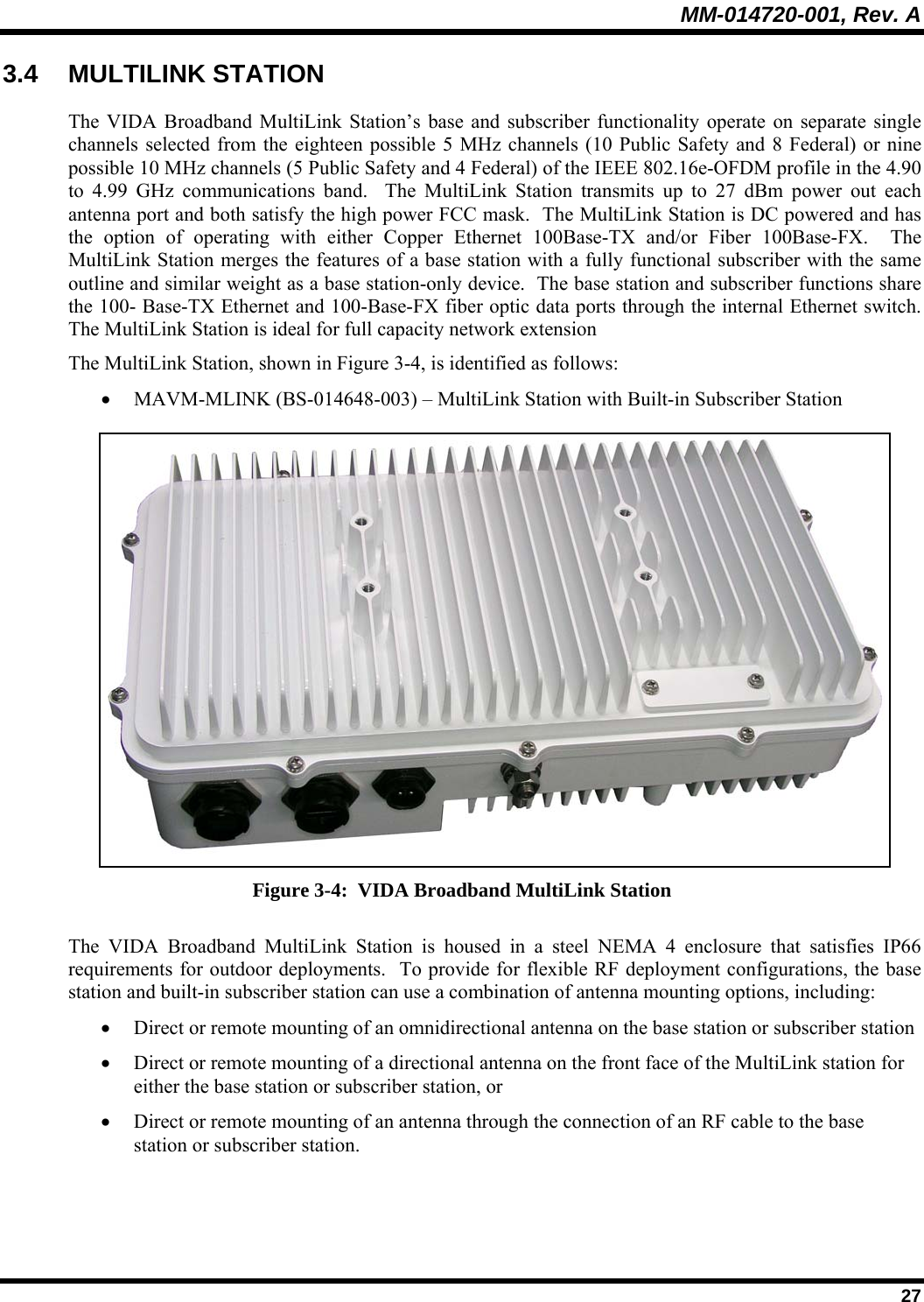
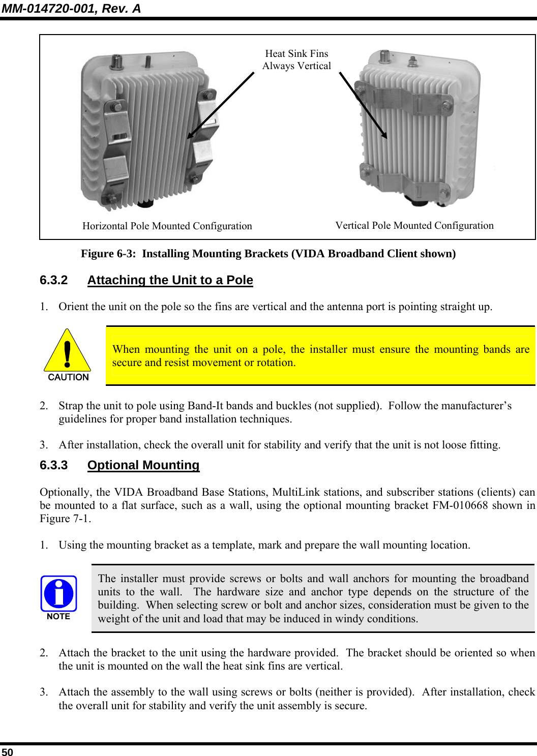
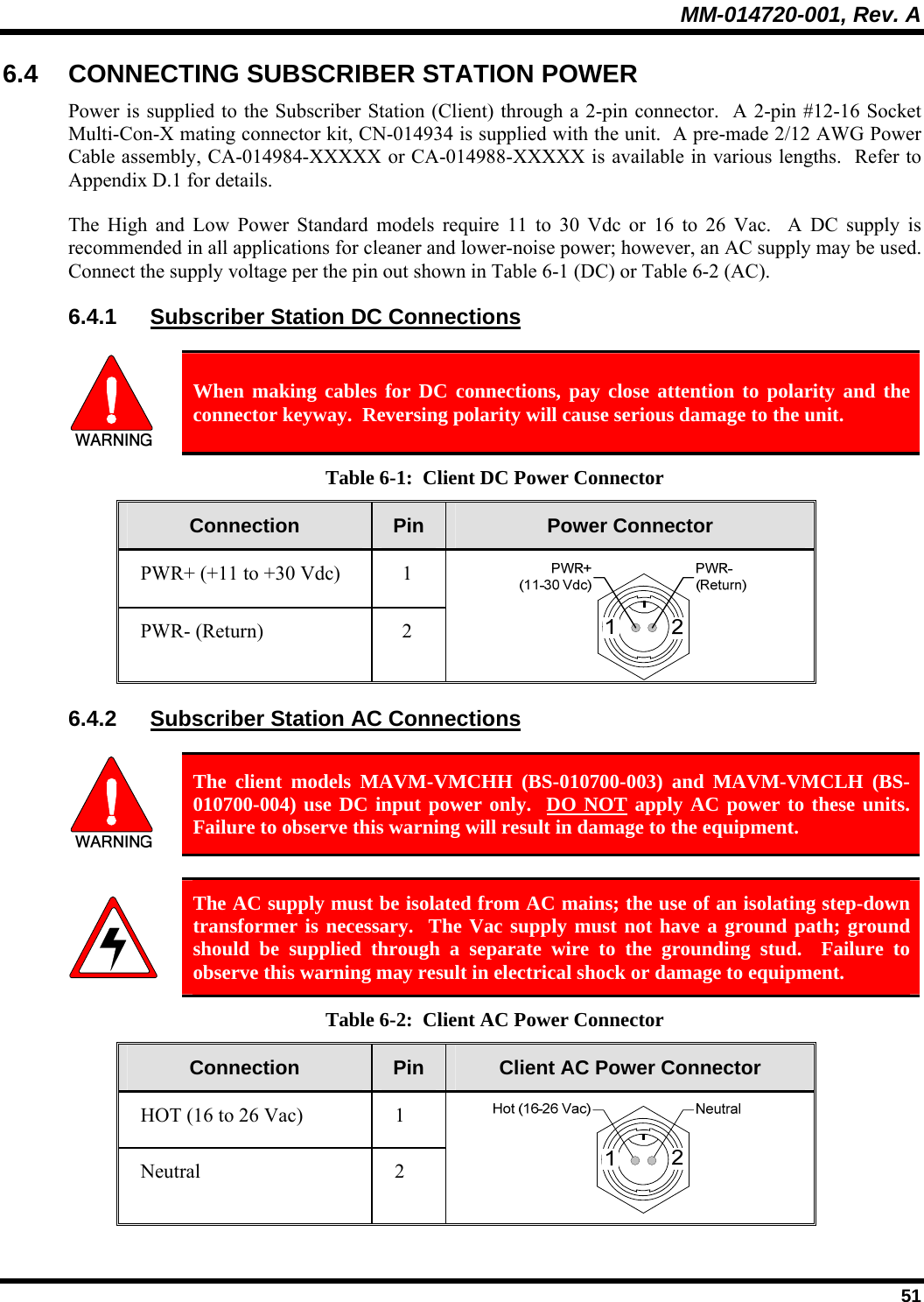
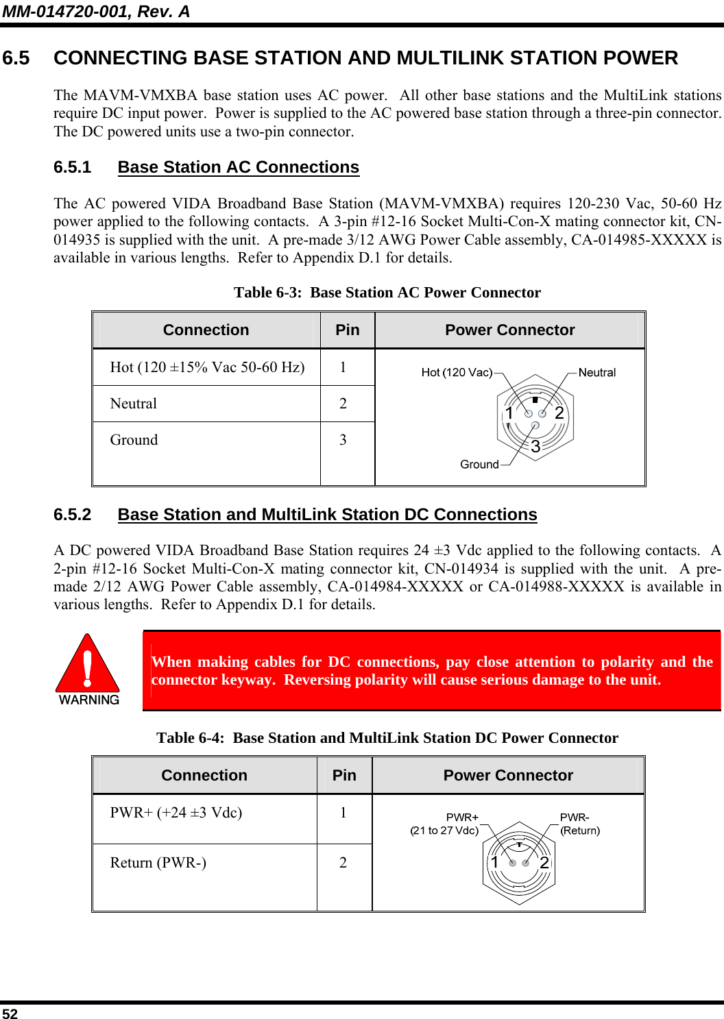
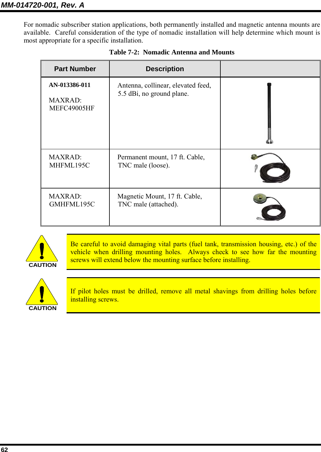
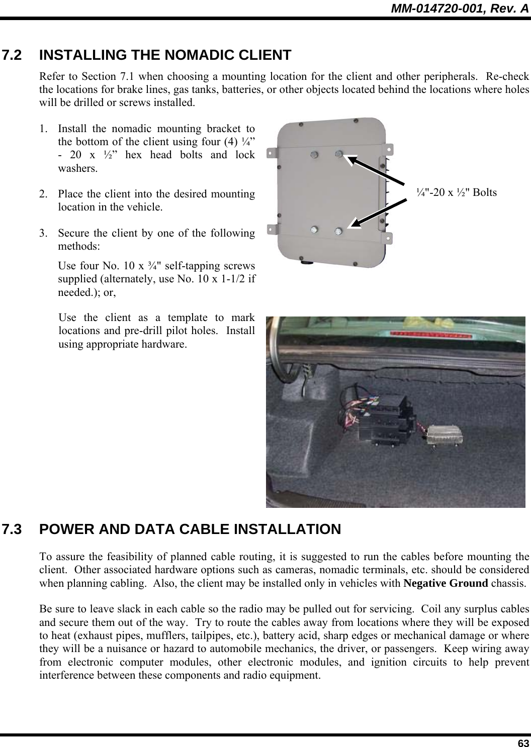
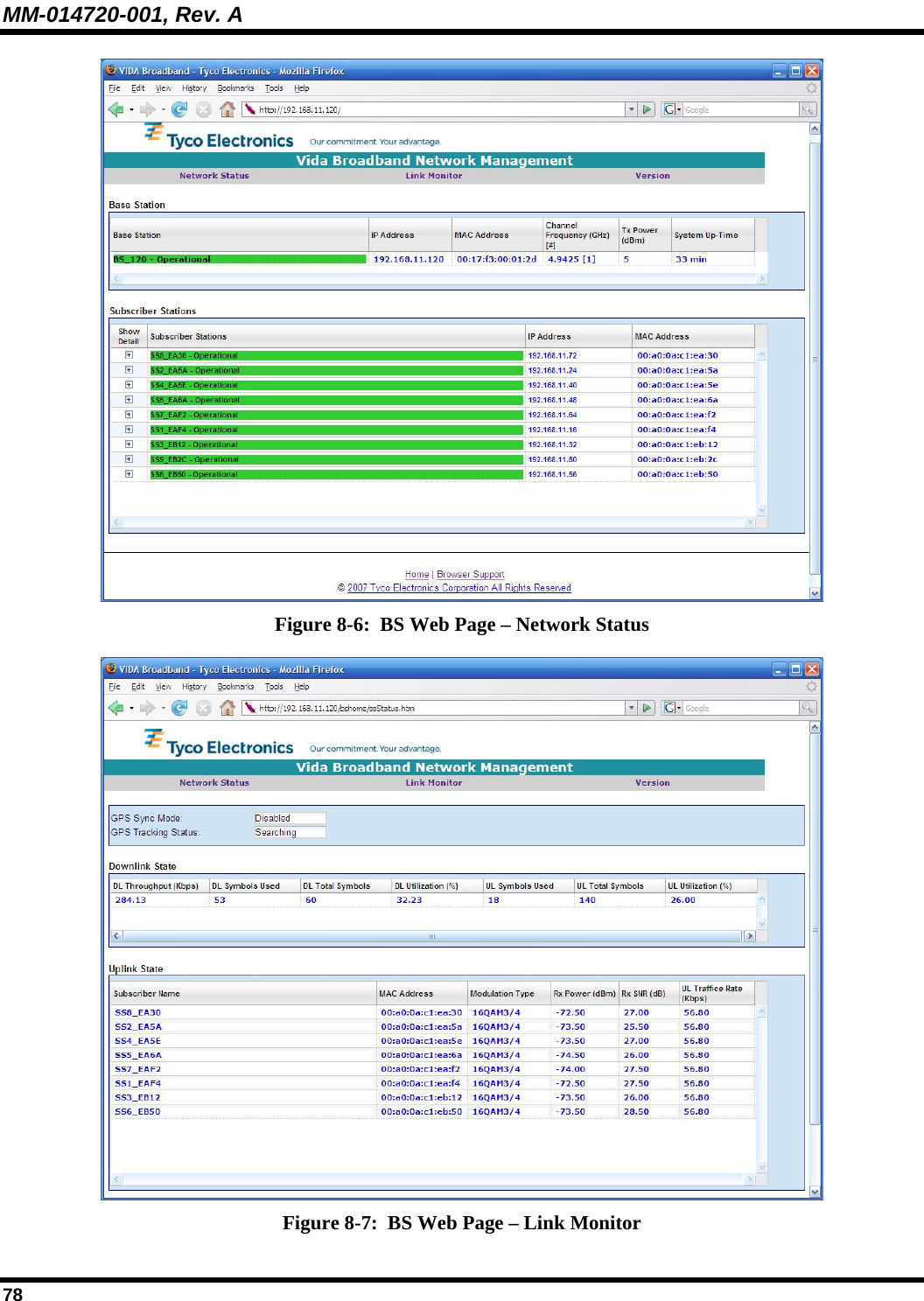
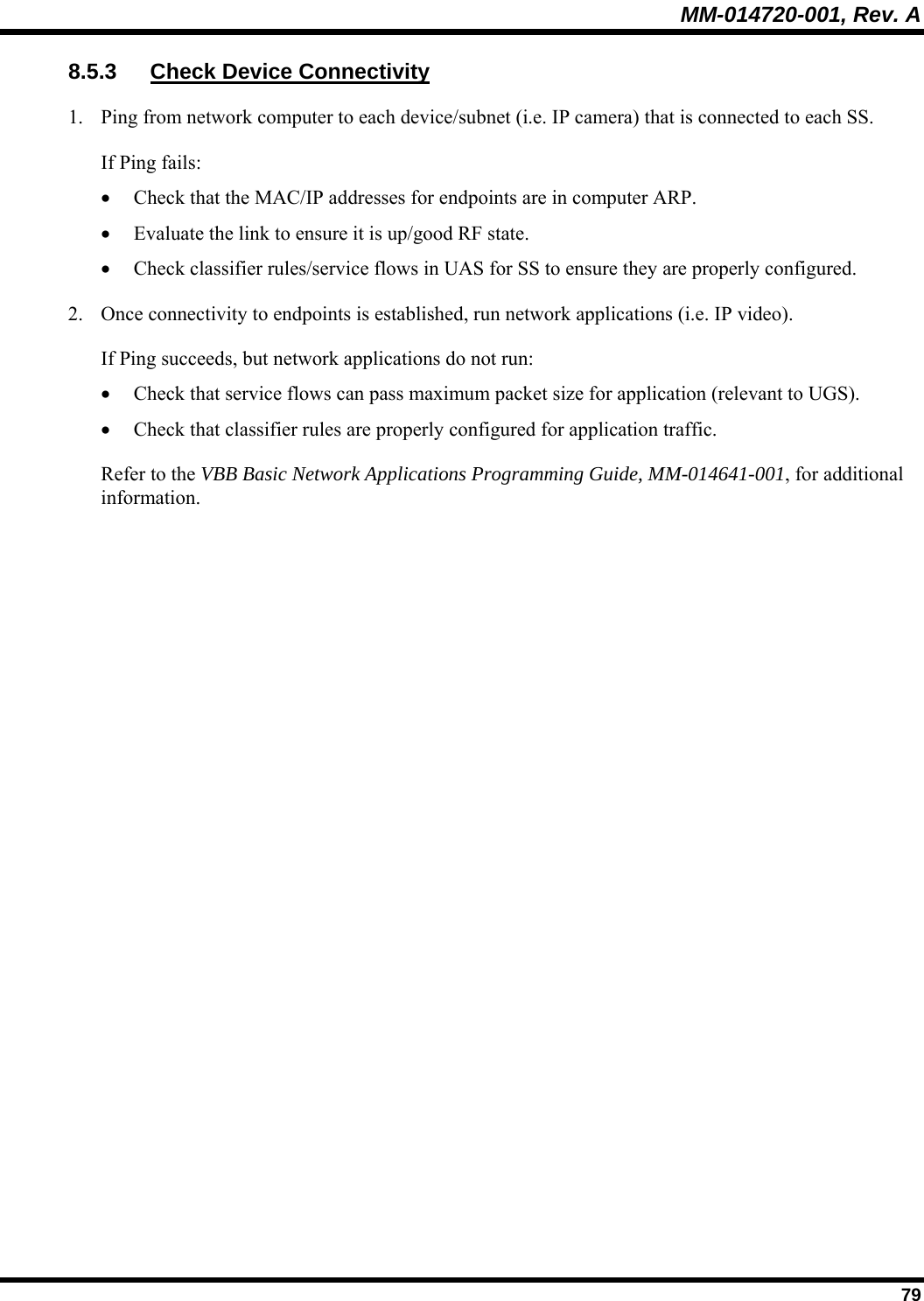
HARRIS MLINK MultiLink Station User Manual Manual 1
Harris Corporation MultiLink Station Manual 1
UserManual.wiki
>
HARRIS
>
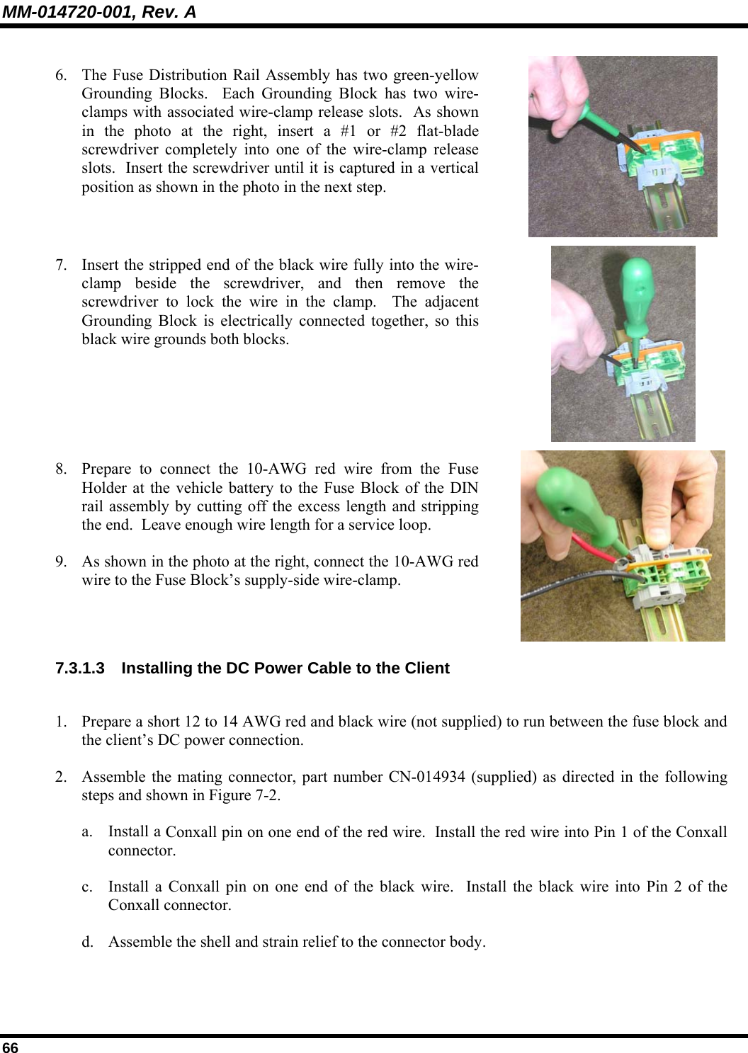
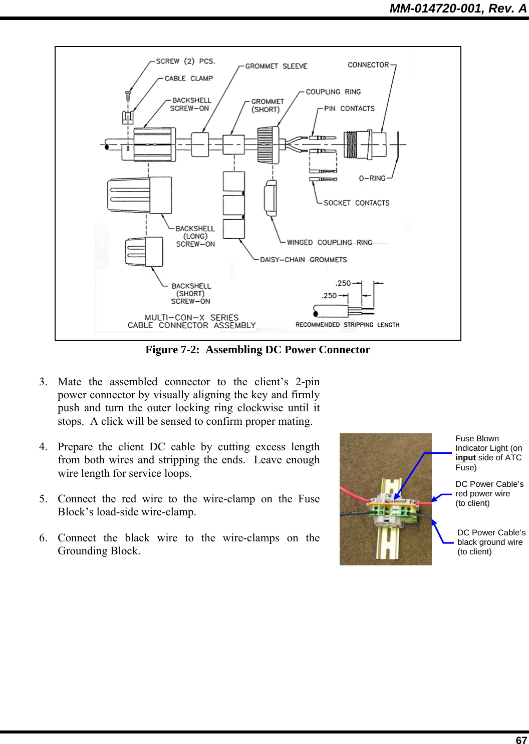
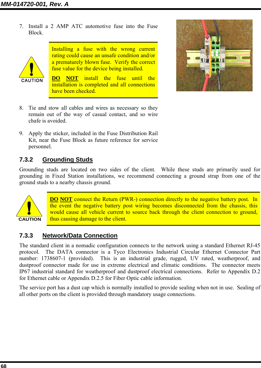
MLINK User Manual
>
Manual 1
Contents
1.
Manual 1
2.
Manual 2
Manual 1
Navigation menu
Upload a User Manual
Namespaces
Wiki Guide
HTML
PDF
Info
Views
User Manual
Discussion / Help
Navigation