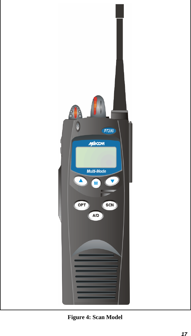
HARRIS P7200 P7200 700/800 MHz Portable Radio User Manual MM23772 p1A
Harris Corporation P7200 700/800 MHz Portable Radio MM23772 p1A
UserManual.wiki
>
HARRIS
>
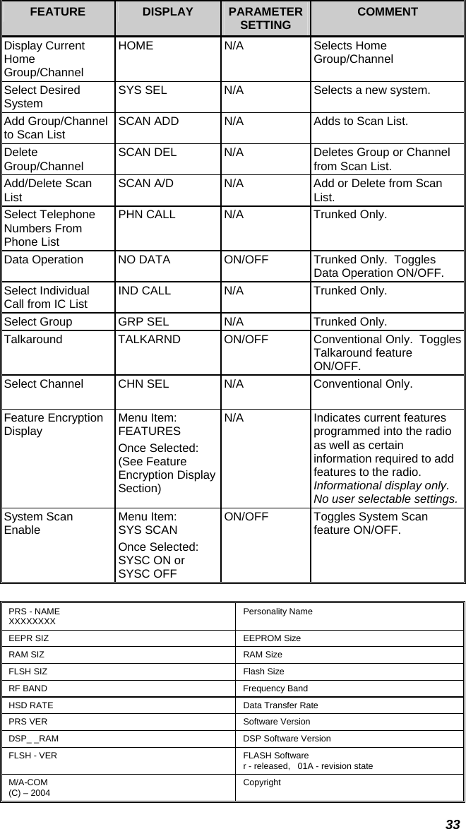
P7200 User Manual
>
Manual 1
Contents
1.
Manual 1
2.
Manual 2
Manual 1
Navigation menu
Upload a User Manual
Namespaces
Wiki Guide
HTML
PDF
Info
Views
User Manual
Discussion / Help
Navigation