Hitec RCD ZEBRA375 REMOTE CONTROL TRANSMITTER User Manual ZEBRA 3FM Manual 8 COVER
Hitec RCD Inc. REMOTE CONTROL TRANSMITTER ZEBRA 3FM Manual 8 COVER
Contents
- 1. USERS MANNUAL 1 OF 2
- 2. USERS MANUAL 2 OF 2
USERS MANNUAL 1 OF 2
8
A. TX Antenna (#58005)
B. Neck strap (#58311)
C. Trainer cord (#58318)
D. Switch harness (#57215S)
E. Heavy duty gold pin switch harness (#54407) This can be removed
F. Stick extensions (#56381)
G. Flight Preserver (#58480)
4. REPLACEMENT PARTS & ACCESSORIES
Congratulations again and have fun!
Austria, Belgium, Denmark, Finland,
France, Germany, Greece, Iceland,
Ireland, The Netherland, Italy, Spain,
Norway, Portugal, United Kingdom,
Luxembourg, Sweden, Switzerland
MADE IN THE PHILIPPINES
Zebra 3 FM Instruction Manual
The following is a listing of replacement parts and
accessories available for the Zebra radio series from your hobby dealer.
- Always turn your transmitter on first and off last.
- Never operate your system without first performing a proper range check.
- FCC regulation in the USA prohibits changing the crystal in your transmitter.
For channel changes send your system to an authorized service/repair center.
- Never fly around or over houses, people or power lines.
- Always charge your batteries before you fly.
- It's a good idea to check your receiver batteries with a tester
This will verify the charge level in your receiver batteries.
- Always fly responsibly and respect the rights of others.
- Make sure your frequency is clear before turning on your system.
5. PRECAUTIONS
Instruction Manual
2 3
Introduction
Thank you for purchasing the Zebra 3 FM digital proportional radio control system.
The Zebra 3 FM is easy to use and utilizes the latest in solid-state components for
unsurpassed reliability and performance. It is important that you read and understand this manual
before you operate your system.
CONTENTS
1. TRANSMITTER
A. Features
- Ergonomically designed 3 channel FM transmitter.
- Precision gimbals.
- Neutral position adjustment for throttle
- SMT circuitry
- Servo reversing on CH1, CH2.
- CH1, CH2 Mixing. (Aero only)
- SIC(Simulating Interface Cable) Compatible
- Easy to read 1 LED battery indicators.
- Size: 174 x 168mm (6.85 x 6.61 in)
- Weight: 330g
- Power supply: 7.2V (6 cell) NiCd or NiMh battery or 6cell Dry battery
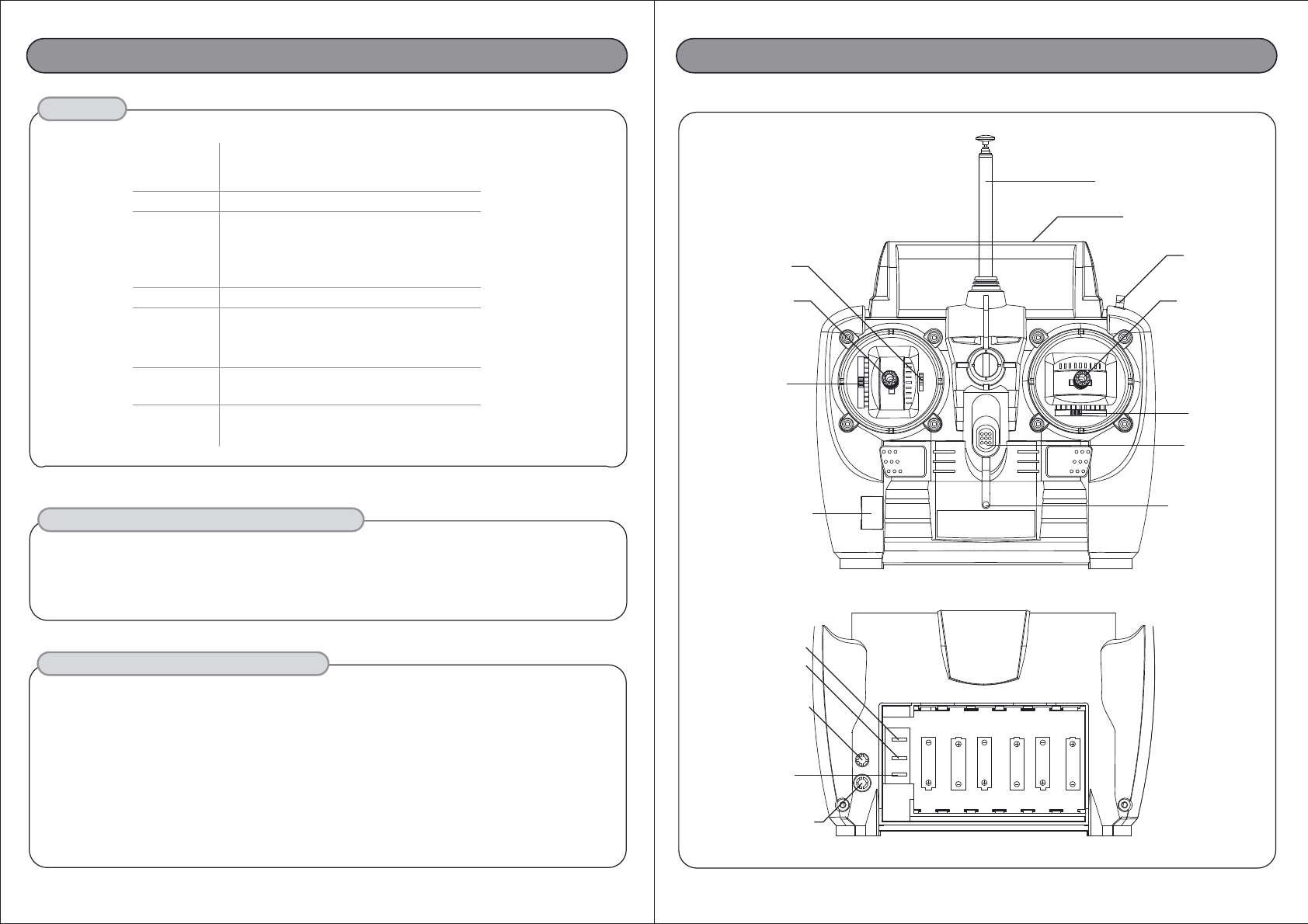
B. Layout
TRANSMITTER
ANTENNA
CARRYING
HANDLE
L.E.D
INDICATOR
TRANSMITTER
CRYSTAL
Ch.2 THROTTLE
CONTROL STICK
NEUTRAL POSITION
ADJUSTMENT LEVER
THROTTLE
TRIM LEVER
STEERING
TRIM LEVER
Ch.1 STEERING
CONTROL STICK
POWER
ON/OFF SWITCH
Ch.3 Slide Switch
THROTTLE SERVO
REVERSE SHUNT SWITCH
CHARGING JACK
MIXING SHUNT SWITCH
(Aero Only)
SIC JACK(Aero Only)
STEERING SERVO
REVERSE SHUNT SWITCH
FRONT
BACK
Zebra 3 FM Instruction ManualZebra 3 FM Instruction Manual
1. Transmitter
a. Features
b. Layout
c. Servo Reversing
d. Mixing (Aero only)
e. Trim lever
f. Reading the LED Battery Indicator
2. Battery Installation
3. Operation
a. Installation of Receiver and Servos
b. Transmitter, Receiver and Servo Settings
c. Simulator System
d. Range checking
4. Replacement Parts & Accessories
5. Precautions
Page 2.
Page 3
Page 4.
Page 5.
Page 6.
Page 7.
Page 8.
4 5
1. The transmitter requires six and the receiver battery pack needs four AA size batteries.
These can be Alkaline, Ni-cd or Ni-Mh cells
2. Always make sure that the receiver and transmitter are off before loading the battery.
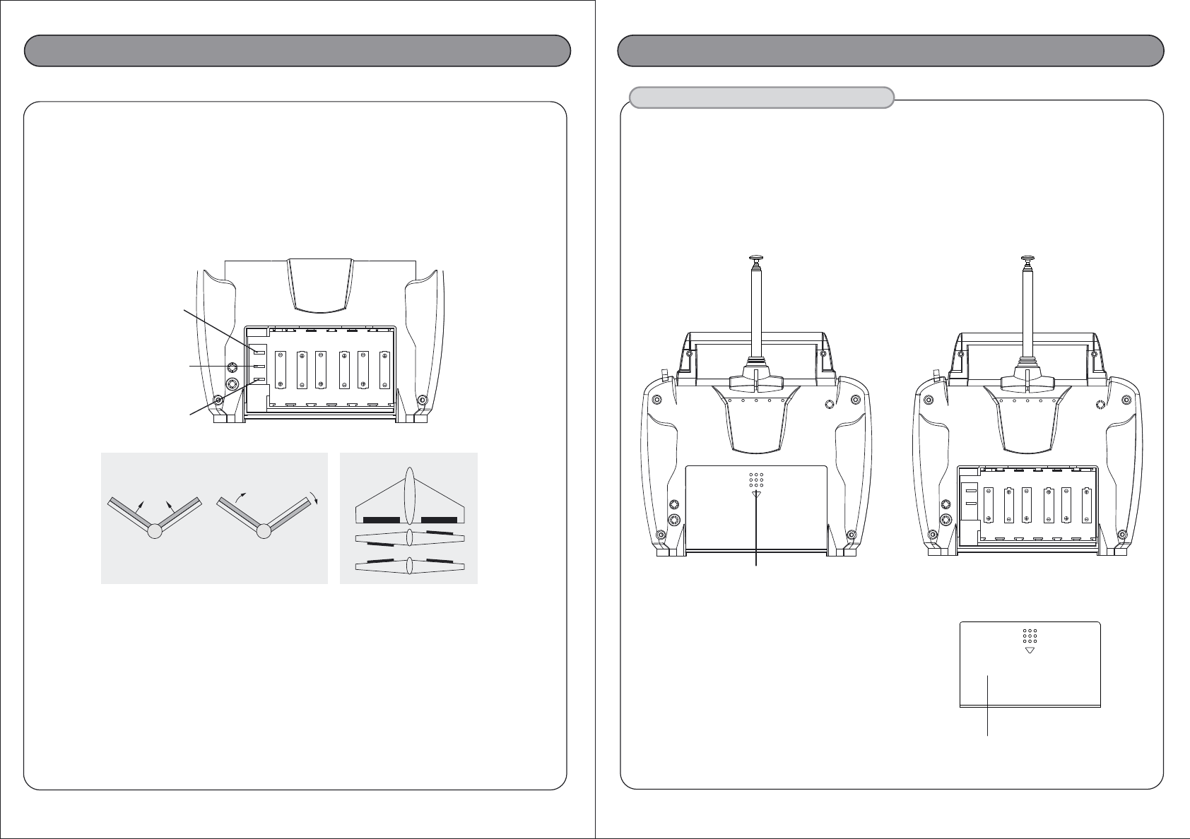
3. Open the battery cover in the back of the transmitter.
4. Load batteries into the appropriate slots, install the batteries with correct polarity as shown.
5. Always return the battery cover first before turning the transmitter power on.
C. Servo Reversing
- The Zebra 3 FM transmitter is equipped with servo reversing on CH1, CH2.
- If you need to change travel direction of rotation, open the battery case and pull the
shunt switch there should be a picture of how to do this and put it to the opposite side again.
D. Mixing (Aero version only)
- The Zebra 3 FM Aero transmitters is equipped with a switch that will mix CH1 and
CH2 for Elevon /V-tail aircraft, or common flying wing type aircraft.
-Put the shunt switch into left side(ch1,2)
-If you don't need mixing, leave shunt switch in right side
E. Trim Levers
- The trim levers associated with each control stick are used to correct or (trim-out) the tracking of the aircraft.
- Make sure that the trims will move the surface past neutral when moved to their extremes.
This will assure you have adequate trim control.
- After your plane's first test flight, note the positions of the control surfaces that required trim.
Next, center the trims and turn the receiver off. Now adjust the control linkage on the plane so the
surfaces are in the same position before the trim levers were re-centered.
- Turn on the radio and receiver and recheck the control surfaces to ensure that all
the corrections were applied in the proper direction.
F. Reading the LED Battery Indicator
- There is one indicator light on the face of the radio marked High (solid glowing LED) and Low (blinking LED).
- These relate to the condition of your transmitter battery. Please pay attention to these LEDs and
stop flying when the LED light is blinking.
2. BATTERY INSTALLATION
Zebra 3 FM Instruction ManualZebra 3 FM Instruction Manual
Ch.2 THROTTLE SERVO
REVERSE SHUNT SWITCH
MIXING SHUNT SWITCH
Ch.1 STEERING SERVO
REVERSE SHUNT SWITCH
BACK
CH1 CH2 CH1 CH2
Up Elevator Right Rudder (view from rear)
V-Tail MIXING Elevon MIXING
CH1 CH2
Aileron Operation
Elevator Operation
BATTERY COVER
6 AA SIZE BATTERY MUST BE
LOADED IN CORRECT
POLARITY AS SHOWN
TO OPEN THE BATTERY COVER
OF THE ZEBRA 3 FM, YOU NEED TO
PRESS THIS AND PUSH IT DOWNWARD.
6 7
B. Transmitter, Receiver and Servo Settings
Checking Operation of the Servo
After installation of the servo and receiver into your model is complete,
turn on the transmitter (fully extend the antenna) now turn on the receiver.
Check to see if all servos are working properly.
If not, check the connections and/or make sure that the main battery pack is charged.
If the servos check out is fine, connect the linkage to the servo horns.
Check that the servos are moving in the correct direction.
If not, change the servo direction with the reversing shunt switches located on the bottom of the radio.
The 3rd channel of the Zebra 3 is not reversible.
If everything is checked out, turn off the receiver first, and then turn off the transmitter.
Warning!!! : Do not shorten the length of the receiver antenna by cutting off any excess wire.
This will severely affect the operating range and could result in injury to yourself and others.
D. Range checking
- Always perform a range check before each operation.
- Perform range check by walking away from the aircraft with the transmitter antenna collapsed.
- You should have complete control from a distance of 60 - 90ft ( 20 - 30m ).
- If the controls are erratic before the minimum distance is reached, do not fly until the problem is resolved.
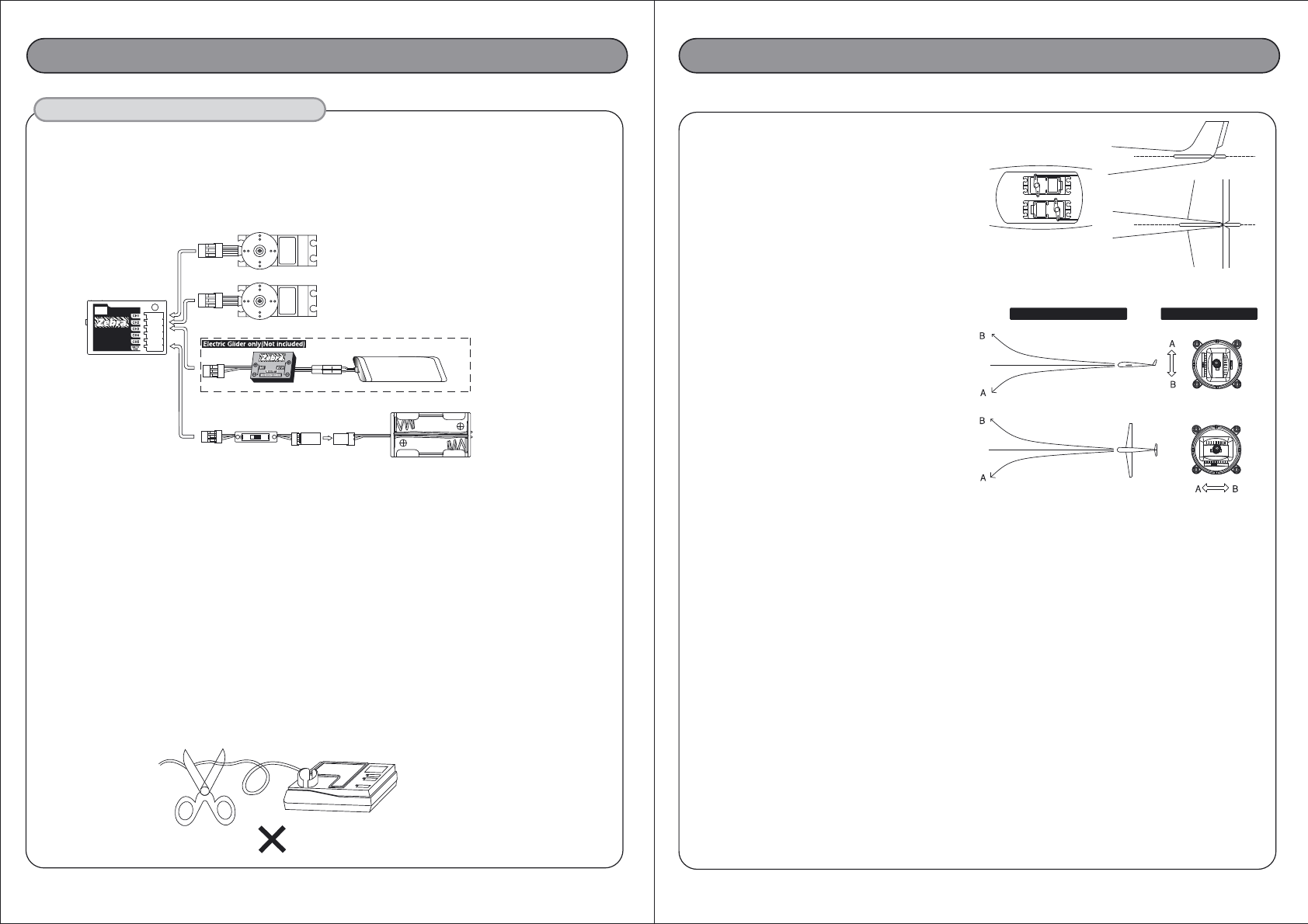
Elevator and Aileron Servo Trim Settings
- Trim Setting before Flight
The servo trim enables minor adjustment of the servo
neutral position so that the plane will fly straight when
the stick is in the center position. Before adjusting the
servo trim, please make sure that when both the stick
and the servo trim is in its center position (1) the servo
arm is perpendicular to the push rods, and (2) the elevator
and aileron of the plane is flush with the tail wing.
- Trim Setting during Flight
You may perform some minor trim adjustment
during flight if the plane nose up or down
(Elevator Trim) or sideways (Aileron Trim) when
the stick is in the center position.
However please keep in mind that trim adjustment
is only for minor adjustment and major adjustment
should still be done through push rod (linkage)
adjustment at the model.
Note: There is no trim adjustment on the
3rd channel of the Zebra 3
Zebra 3 FM Instruction ManualZebra 3 FM Instruction Manual
3. OPERATION
A. Installation of Receiver and Servos
After connecting the receiver and servos as below illustration, turn on the power of the transmitter first then turn
on the receiver. (Always turn your transmitter first and off last to prevent lost of control.)
Now, move the controls to see if the servos are moving properly. If not, check your wiring or crystals if the
servos do not move at all.
RX Battery box
S/W HARNESS
Elevator Servo
Channel #2
Aileron or Rudder Servo
Channel #1
-When your plane does this - Move trim like below
Channel #3
7.2V-8.4V Batt.
ZR-106SF
Extra Long Range
FM
C. Simulator system (Aero version only)
- Zebra 3FM system is compatible with SIC (simulator interface cord- Part # 58318, not included)
designed to work with the popular and free FMS flight simulator. (http://www.hitecrcd.com/product_fs.htm)