Hologic PCB01647 RFID interface board for Selenia Dimensions / 3Dimensions Product Line User Manual 3Dimensions System User Guide
Hologic Inc RFID interface board for Selenia Dimensions / 3Dimensions Product Line 3Dimensions System User Guide
Hologic >
Contents
- 1. User manual_3 Dimensions RFID_Updates EN part 1
- 2. User manual_3 Dimensions RFID_Updates EN part 2
User manual_3 Dimensions RFID_Updates EN part 1

3Dimensions™
Digital Mammography System
Digital Tomosynthesis System
User Guide
For Software Version 2.0
Part Number MAN-05085-002
Revision 002
May 2018

© 2017-2018 Hologic, Inc. Printed in the USA. This manual was originally written in English.
Hologic, 3Dimensions, 3D, 3D Mammography, Affirm, C-View, Dimensions, FAST Paddle, Genius, I-View, Selenia, SmartCurve,
and associated logos are trademarks and/or registered trademarks of Hologic, Inc., and/or its subsidiaries in the United States
and/or other countries. All other trademarks, registered trademarks, and product names are the property of their respective
owners.
This product may be protected by one or more U.S. or foreign patents as identified at www.Hologic.com/patents.
Technical Support
USA: +1.877.371.4372
Europe: +32 2 711 4690
Asia: +852 37487700
Australia: +1 800 264 073
All Other: +1 781 999 7750
Email: BreastHealth.Support@hologic.com

3Dimensions System User Guide
Table of Contents
MAN-05085-002 Revision 002 v
DRAFT Preview Copy-Generated May 30, 2018
Table of Contents
List of Figures _________________________________________________________________ xi
List of Tables _________________________________________________________________ xv
1: Introduction __________________________________________________________________1
1.1 Intended Use............................................................................................................................................................ 1
1.1.1 Contraindications ..................................................................................................................................... 1
1.2 Potential Adverse Effects of Mammography Systems on Health .................................................................... 2
1.3 System Capabilities ................................................................................................................................................. 2
1.4 About the Genius 3D Mammography Exam ...................................................................................................... 2
1.5 More Information About Tomosynthesis ............................................................................................................ 3
1.6 About C-View and Intelligent 2D ......................................................................................................................... 5
1.6.1 C-View and Intelligent 2D Software ...................................................................................................... 5
1.6.2 C-View and Intelligent 2D Warnings .................................................................................................... 5
1.6.3 C-View and Intelligent 2D Theory of Operation .................................................................................. 6
1.7 User Profiles............................................................................................................................................................. 6
1.7.1 Mammography Technologist .................................................................................................................. 6
1.7.2 Radiologist ................................................................................................................................................. 6
1.7.3 Medical Physicist ...................................................................................................................................... 7
1.8 Training Requirements .......................................................................................................................................... 7
1.9 Quality Control Requirements .............................................................................................................................. 7
1.10 Where to Find the Installation Instructions ......................................................................................................... 7
1.11 Where to Find Technical Description Information ............................................................................................. 7
1.12 Warranty Statement ................................................................................................................................................ 8
1.13 Technical Support ................................................................................................................................................... 8
1.14 Product Complaints ................................................................................................................................................ 8
1.15 Hologic Cybersecurity Statement ......................................................................................................................... 8
1.16 Symbols .................................................................................................................................................................... 9
1.17 Descriptions of Warnings, Cautions, and Notes .............................................................................................. 10
1.18 Document Conventions ....................................................................................................................................... 10
2: General Information __________________________________________________________11
2.1 System Overview .................................................................................................................................................. 11
2.1.1 C-Arm Overview .................................................................................................................................... 12
2.2 Safety Information ................................................................................................................................................ 13
2.3 Warnings and Precautions ................................................................................................................................... 13
2.4 Emergency Off Switches ...................................................................................................................................... 17
2.5 Interlocks ................................................................................................................................................................ 18
2.6 Compliance ............................................................................................................................................................ 18
2.6.1 Compliance Requirements .................................................................................................................... 18
2.6.2 Compliance Statements ......................................................................................................................... 20
2.7 Label Locations ..................................................................................................................................................... 21

3Dimensions System User Guide
Table of Contents
vi MAN-05085-002 Revision 002
DRAFT Preview Copy-Generated May 30, 2018
3: System Controls and Indicators ________________________________________________23
3.1 System Power Controls ........................................................................................................................................ 23
3.2 Tubestand Controls and Indicators .................................................................................................................... 24
3.2.1 Tubehead Display ................................................................................................................................... 25
3.2.2 Compression Device Controls and Display ........................................................................................ 25
3.2.3 C-Arm Control Panels ............................................................................................................................ 26
3.2.4 Gantry Control Panels ............................................................................................................................ 26
3.2.5 Dual Function Footswitch ..................................................................................................................... 27
3.3 Universal Acquisition Workstation Controls and Displays ............................................................................ 28
4: Startup, Functional Tests, and Shutdown _______________________________________29
4.1 How to Start the System ....................................................................................................................................... 29
4.2 Log In ...................................................................................................................................................................... 31
4.3 Perform the Functional Tests ............................................................................................................................... 32
4.3.1 Compression Functional Tests .............................................................................................................. 33
4.3.2 C-Arm Movement Functional Tests ..................................................................................................... 34
4.3.3 Collimation .............................................................................................................................................. 42
4.3.4 Shifting Paddles ...................................................................................................................................... 43
4.4 Emergency Off Switches Functionality .............................................................................................................. 44
4.5 How to Turn Off the System ............................................................................................................................... 44
4.6 How to Remove All Power from the System .................................................................................................... 44
5: User Interface ________________________________________________________________45
5.1 Select Function to Perform Screen ...................................................................................................................... 45
5.2 About the Taskbar ................................................................................................................................................. 46
5.3 Select Patient Screen ............................................................................................................................................. 48
5.3.1 About the Notices Tab ........................................................................................................................... 50
5.3.2 Open a Patient ......................................................................................................................................... 50
5.3.3 Add a New Patient ................................................................................................................................. 50
5.3.4 Edit the Patient Information .................................................................................................................. 51
5.3.5 Split the Patient Records ........................................................................................................................ 51
5.3.6 Delete a Patient ....................................................................................................................................... 53
5.3.7 Filters for Patients ................................................................................................................................... 53
5.3.8 Refresh the Worklist ............................................................................................................................... 55
5.3.9 Query the Worklist ................................................................................................................................. 55
5.3.10 Admin ...................................................................................................................................................... 55
5.3.11 Log Out .................................................................................................................................................... 55
5.3.12 Advanced Workflow Manager ............................................................................................................. 56
5.4 Procedure Screen ................................................................................................................................................... 56
5.4.1 How to Use the Implant Present Button .............................................................................................. 57
5.4.2 How to Use the Paddle Shift Feature ................................................................................................... 58
5.4.3 Procedure Information Dialog Box ...................................................................................................... 58
5.4.4 Add a Procedure ..................................................................................................................................... 59
5.4.5 Add (or Remove) a View ....................................................................................................................... 60
5.4.6 Edit a View .............................................................................................................................................. 61

3Dimensions System User Guide
Table of Contents
MAN-05085-002 Revision 002 vii
DRAFT Preview Copy-Generated May 30, 2018
5.4.7 Retrieve .................................................................................................................................................... 61
5.4.8 Close a Patient ......................................................................................................................................... 62
5.5 How to Access the Image Review Features ...................................................................................................... 62
5.6 Output Groups ...................................................................................................................................................... 63
5.6.1 Select an Output Group ......................................................................................................................... 63
5.6.2 Add or Edit an Output Group .............................................................................................................. 63
5.6.3 Custom Output ....................................................................................................................................... 64
5.7 On-Demand Outputs ............................................................................................................................................ 64
5.7.1 Archive ..................................................................................................................................................... 64
5.7.2 Export ....................................................................................................................................................... 65
5.7.3 Print .......................................................................................................................................................... 66
6: Images ______________________________________________________________________69
6.1 Image Display Screen ........................................................................................................................................... 69
6.2 How to Set the Exposure Parameters ................................................................................................................. 70
6.2.1 Select the Image Acquisition Mode (Tomosynthesis Option) .......................................................... 70
6.2.2 Select the Exposure Mode ..................................................................................................................... 70
6.2.3 How to Use the AEC Sensor ................................................................................................................. 70
6.3 How to Acquire an Image .................................................................................................................................... 71
6.3.1 Conventional Imaging Sequence of Events......................................................................................... 72
6.3.2 Tomosynthesis Imaging Sequence of Events ...................................................................................... 72
6.3.3 How to Accept a Rejected Image .......................................................................................................... 73
6.3.4 How to Accept or Reject a Pended Image ........................................................................................... 73
6.4 How to Correct and Reprocess Implant Images ............................................................................................... 73
6.4.1 If the Image Is Not Accepted ................................................................................................................ 73
6.4.2 If the Image Is Accepted ........................................................................................................................ 73
6.5 How to Review the Images .................................................................................................................................. 74
6.5.1 Image Review Tools Tab ........................................................................................................................ 75
6.5.2 Notices Tab .............................................................................................................................................. 76
6.5.3 Other Image Review Tools .................................................................................................................... 77
6.5.4 Slice Indicator .......................................................................................................................................... 78
6.6 How to Send the Images to the Output Devices............................................................................................... 78
6.7 How to Use I-View 2D Contrast ......................................................................................................................... 79
6.7.1 How to Configure Contrast Settings .................................................................................................... 82
7: Accessories __________________________________________________________________83
7.1 How to Install Accessories on the C-Arm ......................................................................................................... 83
7.2 Patient Face Shields .............................................................................................................................................. 84
7.2.1 How to Install and Remove the Retractable Face Shield ................................................................... 84
7.2.2 How to Use the Retractable Face Shield .............................................................................................. 85
7.2.3 How to Install and Remove the Conventional Face Shield .............................................................. 86
7.3 Compression Paddles ........................................................................................................................................... 87
7.3.1 Routine Screening Paddles .................................................................................................................... 88
7.3.2 Contact and Spot Compression Paddles ............................................................................................. 89
7.3.3 Magnification Paddles ........................................................................................................................... 89

3Dimensions System User Guide
Table of Contents
viii MAN-05085-002 Revision 002
DRAFT Preview Copy-Generated May 30, 2018
7.3.4 Localization Paddles .............................................................................................................................. 90
7.3.5 Large Ultrasound Paddle ....................................................................................................................... 90
7.3.6 How to Install and Remove a Compression Paddle .......................................................................... 91
7.3.7 Paddle Maintenance and Cleaning ...................................................................................................... 91
7.3.8 Paddle Shift.............................................................................................................................................. 92
7.3.9 FAST Compression Mode ...................................................................................................................... 92
7.4 Magnification Stand .............................................................................................................................................. 93
7.4.1 How to Install and Remove the Magnification Stand ........................................................................ 93
7.5 Crosshair Devices .................................................................................................................................................. 95
7.5.1 How to Install and Remove the Localization Crosshair Device ....................................................... 95
7.5.2 How to Use the Localization Crosshair Device .................................................................................. 96
7.5.3 How to Install and Remove the Magnification Crosshair Device .................................................... 96
7.5.4 How to Align the Crosshair Device ..................................................................................................... 97
8: Clinical Procedures ___________________________________________________________99
8.1 Standard Workflow .............................................................................................................................................. 99
8.1.1 Preparation .............................................................................................................................................. 99
8.1.2 At the Gantry ........................................................................................................................................... 99
8.1.3 At the Acquisition Workstation .......................................................................................................... 100
8.2 Screening Procedure Example ........................................................................................................................... 100
8.2.1 Position the Patient ............................................................................................................................... 101
8.2.2 Set the Exposure Techniques ............................................................................................................... 101
8.2.3 Acquire the Exposure ........................................................................................................................... 101
8.3 Procedure for Needle Localization with Tomosynthesis .............................................................................. 103
9: Maintenance and Cleaning ___________________________________________________105
9.1 Cleaning ............................................................................................................................................................... 105
9.1.1 General Information About Cleaning ................................................................................................ 105
9.1.2 For General Cleaning ........................................................................................................................... 105
9.1.3 To Prevent Possible Injury or Equipment Damage .......................................................................... 106
9.1.4 Acquisition Workstation ...................................................................................................................... 107
9.2 Maintenance ......................................................................................................................................................... 108
9.2.1 Preventive Maintenance Schedules .................................................................................................... 108
9.2.2 About Reclamation ............................................................................................................................... 110
10: System Administration Interface _____________________________________________111
10.1 Admin Screen ...................................................................................................................................................... 111
10.2 About Screen ........................................................................................................................................................ 113
10.2.1 Licensing Tab ........................................................................................................................................ 114
10.3 Change the User Language Preference ............................................................................................................ 114
10.4 Set Auto-Hanging and Auto-Pairing ............................................................................................................... 115
10.5 Set Multi Line Procedure Tabs .......................................................................................................................... 115
10.6 Enable and Set the Height Memory .................................................................................................................. 116
10.7 Set Auto-Accept and Auto-Pend Images ......................................................................................................... 118
10.8 How to Set the Contrast Defaults ..................................................................................................................... 119

3Dimensions System User Guide
Table of Contents
MAN-05085-002 Revision 002 ix
DRAFT Preview Copy-Generated May 30, 2018
10.9 Enable and Set the Default Height ................................................................................................................... 120
10.10 System Tools ........................................................................................................................................................ 122
10.10.1 System Tools for the Radiologic Technologist Manager ................................................................. 122
10.10.2 Remote Access to Image Reports ....................................................................................................... 124
10.11 Archive Tool ........................................................................................................................................................ 126
Appendix A Specifications _____________________________________________________129
A.1 Product Measurements ...................................................................................................................................... 129
A.1.1 Tubestand (Gantry with C-Arm) ........................................................................................................ 129
A.1.2 Acquisition Workstations .................................................................................................................... 130
A.2 Operation and Storage Environment ............................................................................................................... 131
A.2.1 General Conditions for Operation ...................................................................................................... 131
A.2.2 Storage Environment ........................................................................................................................... 132
A.3 Radiation Shield .................................................................................................................................................. 132
A.4 Electrical Input .................................................................................................................................................... 132
A.4.1 Tubestand .............................................................................................................................................. 132
A.4.2 Acquisition Workstation ...................................................................................................................... 133
A.5 Tubestand Technical Information ..................................................................................................................... 133
A.5.1 C-Arm..................................................................................................................................................... 133
A.5.2 Compression ......................................................................................................................................... 134
A.5.3 X-ray Tube ............................................................................................................................................. 135
A.5.4 X-ray Beam Filtration and Output ..................................................................................................... 135
A.5.5 X-ray Collimation ................................................................................................................................. 137
A.5.6 Light Field Indication ........................................................................................................................... 137
A.5.7 X-ray Generator .................................................................................................................................... 137
A.6 Imaging System Technical Information ........................................................................................................... 138
A.6.1 Image Receptor ..................................................................................................................................... 138
Appendix B System Messages and Alert Messages ________________________________139
B.1 Error Recovery and Troubleshooting ............................................................................................................... 139
B.2 Types of Messages .............................................................................................................................................. 139
B.2.1 Fault Levels ........................................................................................................................................... 139
B.2.2 System Messages .................................................................................................................................. 140
B.3 UPS Messages ...................................................................................................................................................... 142
Appendix C Use of Mobile System ______________________________________________143
C.1 Conditions for Safety and Other Precautions ................................................................................................. 143
C.2 Specifications for Mobile Use ............................................................................................................................ 144
C.2.1 Shock and Vibration Limits ................................................................................................................. 144
C.2.2 Coach Environment .............................................................................................................................. 144
C.3 Electrical Input .................................................................................................................................................... 145
C.3.1 Gantry .................................................................................................................................................... 145
C.3.2 Acquisition Workstation ...................................................................................................................... 145
C.4 Prepare the System for Travel ........................................................................................................................... 146
C.5 Prepare the System for Use ................................................................................................................................ 147

3Dimensions System User Guide
Table of Contents
xMAN-05085-002 Revision 002
DRAFT Preview Copy-Generated May 30, 2018
C.6 Test the System after Travel .............................................................................................................................. 148
C.6.1 Mobile System Controls and Functional Tests ................................................................................. 148
C.7 Quality Control Tests ......................................................................................................................................... 148
Appendix D Dose Information _________________________________________________149
D.1 EUREF Dose Tables ............................................................................................................................................ 149
Glossary of Terms _____________________________________________________________151
Index ________________________________________________________________________153

3Dimensions System User Guide
Table of Contents
MAN-05085-002 Revision 002 xi
DRAFT Preview Copy-Generated May 30, 2018
List of Figures
Figure 1: 3Dimensions™ System ................................................................................................................................... 11
Figure 2: C-arm Overview .............................................................................................................................................. 12
Figure 3: Emergency Off Switch Functionality ............................................................................................................ 17
Figure 4: Label Locations ................................................................................................................................................ 21
Figure 5: System Power Controls .................................................................................................................................. 23
Figure 6: Tubestand Controls and Indicators .............................................................................................................. 24
Figure 7: Tubehead Display ........................................................................................................................................... 25
Figure 8: Compression Device ....................................................................................................................................... 25
Figure 9: Compression Device Display ......................................................................................................................... 25
Figure 10: C-arm Control Panel ..................................................................................................................................... 26
Figure 11: Gantry Control Panel .................................................................................................................................... 26
Figure 12: Dual Function Footswitch ............................................................................................................................ 27
Figure 13: Universal Acquisition Workstation Controls and Displays .................................................................... 28
Figure 14: Turn to Reset the Emergency Off Switches................................................................................................ 29
Figure 15: Universal Acquisition Workstation Power Buttons ................................................................................. 29
Figure 16: Startup Screen ................................................................................................................................................ 30
Figure 17: Select an Operator (Log In) Screen .............................................................................................................. 31
Figure 18: C-arm Control Panel (left side shown) ....................................................................................................... 32
Figure 19: Emergency Off Switch Functionality .......................................................................................................... 44
Figure 20: Universal Acquisition Workstation Power Buttons ................................................................................. 44
Figure 21: An Example Select Function to Perform Screen ........................................................................................ 45
Figure 22: Taskbar............................................................................................................................................................ 46
Figure 23: Select Patient Screen ...................................................................................................................................... 48
Figure 24: Enterprise Tab ................................................................................................................................................ 49
Figure 25: Add Patient Screen ........................................................................................................................................ 50
Figure 26: Split Patient Records Screen......................................................................................................................... 51
Figure 27: Select the Correct Procedure to Split Patient Records .............................................................................. 52
Figure 28: Filter Tab in the Patient Filter Screen .......................................................................................................... 53
Figure 29: Procedure Screen ........................................................................................................................................... 56
Figure 30: Paddle Shift Buttons ...................................................................................................................................... 58
Figure 31: Procedure Info Dialog Box ........................................................................................................................... 58
Figure 32: Add Procedure Dialog Box .......................................................................................................................... 59
Figure 33: Add View Screen ........................................................................................................................................... 60
Figure 34: Edit View Screen ............................................................................................................................................ 61
Figure 35: Output Groups Field ..................................................................................................................................... 63
Figure 36: An Example Custom Output Group ........................................................................................................... 64
Figure 37: Select the Images for Export ........................................................................................................................ 65
Figure 38: Export Dialog Box ......................................................................................................................................... 66
Figure 39: Print Screen .................................................................................................................................................... 67
Figure 40: Image Display Screen.................................................................................................................................... 69
Figure 41: Exposure In Progress .................................................................................................................................... 71
Figure 42: Exposure Complete ....................................................................................................................................... 71

3Dimensions System User Guide
Table of Contents
xii MAN-05085-002 Revision 002
DRAFT Preview Copy-Generated May 30, 2018
Figure 43: Marked Images in a Procedure .................................................................................................................... 72
Figure 44: Tools Tab (Tomosynthesis option shown) ................................................................................................. 74
Figure 45: Image Review Tools ...................................................................................................................................... 75
Figure 46: Tools on the Notices Tab .............................................................................................................................. 76
Figure 47: Exposure Index .............................................................................................................................................. 77
Figure 48: Display Modes ............................................................................................................................................... 77
Figure 49: Slice Indicator ................................................................................................................................................. 78
Figure 50: I-View 2D Contrast Screen ........................................................................................................................... 79
Figure 51: I-View 2D Contrast Screen, Waiting Period .............................................................................................. 80
Figure 52: I-View 2D Contrast Screen, Optimal Imaging Period .............................................................................. 81
Figure 53: I-View 2D Contrast Information .................................................................................................................. 82
Figure 54: C-arm Accessories ......................................................................................................................................... 83
Figure 55: Align the Retractable Face Shield on the C-arm ........................................................................................ 84
Figure 56: Face Shield Installation ................................................................................................................................. 85
Figure 57: Face Shield Operation ................................................................................................................................... 85
Figure 58: How to Install the Conventional Face Shield ............................................................................................ 86
Figure 59: How to Install a Compression Paddle ........................................................................................................ 91
Figure 60: How to Remove a Compression Paddle ..................................................................................................... 91
Figure 61: The FAST Compression Mode Slide ........................................................................................................... 93
Figure 62: Installation of the Magnification Stand ...................................................................................................... 93
Figure 63: Installation of the Localization Crosshair Device ..................................................................................... 95
Figure 64: How to Install and Remove the Magnification Crosshair Device ........................................................... 96
Figure 65: Example of a Screening Procedure Screen ............................................................................................... 100
Figure 66: Exposure In Progress .................................................................................................................................. 102
Figure 67: Exposure Complete ..................................................................................................................................... 102
Figure 68: Calculating needle depth ............................................................................................................................ 104
Figure 69: Admin Screen ............................................................................................................................................... 111
Figure 70: System Tab of the About (the Acquisition Workstation) Screen ........................................................... 113
Figure 71: Licensing Tab of the About Screen ............................................................................................................ 114
Figure 72: Enable Auto-Hanging and Auto-Pairing ................................................................................................. 115
Figure 73: Enable Multi Line Procedure Tabs ............................................................................................................ 116
Figure 74: My Settings Button in the Admin Screen ................................................................................................. 116
Figure 75: Console Tab of the Edit Operator Screen ................................................................................................. 117
Figure 76: Height Adjust Control Panel ...................................................................................................................... 117
Figure 77: Desired Console Height and Current Console Height Fields ............................................................... 117
Figure 78: Set Image Auto Disposition ....................................................................................................................... 118
Figure 79: I-View 2D Contrast Default Settings ......................................................................................................... 119
Figure 80: Preferences Button in the Admin Screen .................................................................................................. 120
Figure 81: Console Tab of the System Preferences Screen ........................................................................................ 120
Figure 82: Height Adjust Control Panel ...................................................................................................................... 121
Figure 83: Desired Console Height and Current Console Height Fields ............................................................... 121
Figure 84: System Tools Button .................................................................................................................................... 122
Figure 85: System Tools Screen .................................................................................................................................... 122
Figure 86: Remote Logon Screen for Service Tools ................................................................................................... 124
Figure 87: Service Tools Welcome Screen ................................................................................................................... 125

3Dimensions System User Guide
Table of Contents
MAN-05085-002 Revision 002 xiii
DRAFT Preview Copy-Generated May 30, 2018
Figure 88: Create Image Report Parameters .............................................................................................................. 125
Figure 89: Create Image Report ................................................................................................................................... 126
Figure 90: Archive Button ............................................................................................................................................. 126
Figure 91: Multi Patient On Demand Archive Screen .............................................................................................. 127
Figure 92: Export Screen ............................................................................................................................................... 128
Figure 93: Tubestand (Gantry with C-arm) Measurements ..................................................................................... 129
Figure 94: Universal Acquisition Workstation Measurements ............................................................................... 130
Figure 95: Mobile Universal Acquisition Workstation Measurements .................................................................. 131
Figure 96: UPS LCD Display ........................................................................................................................................ 142
Figure 97: Keyboard Tray Lock Knob ......................................................................................................................... 146
Figure 98: Keyboard Tray Lock Knob ......................................................................................................................... 146
Figure 99: Tray Lock Release from Locked (A) to Unlocked (D) ............................................................................ 146
Figure 100: Swivel Lock Knobs for Image Display Monitor on Mobile Universal Acquisition Workstation ... 147
Figure 101: Tray Lock Release from Locked (A) to Unlocked (D) .......................................................................... 147
Figure 102: Swivel Lock Knobs for Image Display Monitor on Mobile Universal Acquisition Workstation ... 148

3Dimensions System User Guide
Table of Contents
MAN-05085-002 Revision 002 xv
DRAFT Preview Copy-Generated May 30, 2018
List of Tables
Table 1: System Labels .................................................................................................................................................... 22
Table 2: Compression Tests ............................................................................................................................................ 33
Table 3: C-arm Up and Down Movement .................................................................................................................... 34
Table 4: C-arm Counterclockwise Rotation .................................................................................................................. 36
Table 5: C-arm Clockwise Rotation ............................................................................................................................... 37
Table 6: C-arm Rotation Switch ..................................................................................................................................... 38
Table 7: Automatic C-arm Counterclockwise Rotation .............................................................................................. 39
Table 8: Automatic C-arm Clockwise Rotation ........................................................................................................... 40
Table 9: Automatic MLO Rotation ................................................................................................................................ 41
Table 10: C-arm Collimation .......................................................................................................................................... 42
Table 11: Shifting Paddle ................................................................................................................................................ 43
Table 12: Taskbar Menus ................................................................................................................................................ 46
Table 13: The Select Patient Screen ................................................................................................................................ 48
Table 14: Filter Tab Options (Require Access Privileges) ........................................................................................... 54
Table 15: The Procedure Screen ..................................................................................................................................... 57
Table 16: Procedure Groups ........................................................................................................................................... 59
Table 17: Available Accessories ..................................................................................................................................... 87
Table 18: User Preventive Maintenance ...................................................................................................................... 108
Table 19: Service Engineer Preventive Maintenance ................................................................................................ 109
Table 20: Admin Screen Functions .............................................................................................................................. 111
Table 21: Radiologic Technologist Manager—System Tools Functions ................................................................. 123
Table 22: Maximum mA Setting as a Function of kV ............................................................................................... 135
Table 23: System Messages ........................................................................................................................................... 140
Table 24: 2D Dose (EUREF) .......................................................................................................................................... 149
Table 25: BT Dose (EUREF) .......................................................................................................................................... 149
Table 26: CEDM Dose (EUREF) ................................................................................................................................... 150
3Dimensions System User Guide
Chapter 1: Introduction
MAN-05085-002 Revision 002 Page 1
DRAFT Preview Copy-Generated May 30, 2018
1: Introduction
Read all this information carefully before operating the system. Follow all warnings and
precautions as stated in this manual. Keep this manual available during procedures.
Physicians should tell patients about all potential risks and adverse events described in
this manual with respect to the operation of the system.
Note
Hologic configures some systems to meet specific requirements. Your system
configuration may not have all the options and accessories included in this manual.
1.1 Intended Use
Caution: Federal law restricts this device to sale by or on the order of a physician.
The Hologic® 3Dimensions™ system is indicated to generate digital mammographic
images that can be used for screening and diagnosis of breast cancer. The 3Dimensions
(2D or 3D) system is intended for use in the same clinical applications as a 2D
mammography system for screening mammograms. Specifically, the 3Dimensions
system can be used to generate 2D digital mammograms and 3D mammograms. Each
screening examination may consist of:
•a 2D FFDM image set
- OR -
•a 2D and 3D image set, where the 2D image can be either an FFDM or a 2D
image generated from the 3D image set
The 3Dimensions system may also be used for additional diagnostic workup of the
breast.
Note
In Canada and Singapore, Tomosynthesis is not approved for screening, and must be
used in conjunction with a 2D image (either a FFDM image or 2D image generated from
the 3D image set).
Contrast Enhanced Digital Mammography
Contrast Enhanced Digital Mammography (CEDM) is an extension of the existing
indication for diagnostic mammography with the 3Dimensions system. The CEDM
application shall enable contrast enhanced breast imaging using a dual energy technique.
This imaging technique can be used as an adjunct following mammography and/or
ultrasound exams to localize a known or suspected lesion.
1.1.1 Contraindications
There are no known contraindications.
Chapter 1

3Dimensions System User Guide
Chapter 1: Introduction
Page 2 MAN-05085-002 Revision 002
DRAFT Preview Copy-Generated May 30, 2018
1.2 Potential Adverse Effects of Mammography Systems on
Health
Below is a list of the potential adverse effects (such as complications) associated with the
use of the device (these risks are the same as for other screen-film or digital
mammography systems):
•Excessive breast compression
•Excessive x-ray exposure
•Electric shock
•Infection
•Skin irritation, abrasions, or puncture wounds
1.3 System Capabilities
The system provides the user interfaces for the performance of screening and diagnostic
mammograms:
•Conventional mammography with a digital image receptor equivalent in size to large
mammography film.
•Tomosynthesis scan with a digital image receptor equivalent in size to large
mammography film (Tomosynthesis option).
•Conventional digital mammogram and tomosynthesis scan during one compression
(Tomosynthesis option).
1.4 About the Genius 3D Mammography Exam
The Genius™ 3D Mammography™ exam (also known as Genius™ exam) is acquired on
a Hologic® 3D Mammography™ system, and has a 2D and 3D™ image set. The 2D image
can be either an acquired 2D image or a 2D image generated from the 3D™ image set.
The Genius™ exam is only available on a Hologic® 3D Mammography™ system.
Genius™ 3D Mammography™ is the brand name of a Hologic 3D Mammography™
exam, and may not be available in all markets.

3Dimensions System User Guide
Chapter 1: Introduction
MAN-05085-002 Revision 002 Page 3
DRAFT Preview Copy-Generated May 30, 2018
1.5 More Information About Tomosynthesis
The Hologic Selenia Dimensions system received FDA approval for the Hologic
Tomosynthesis option on 11 Feb 2011 (refer to PMA number P080003). This FDA
approval applies to screening and diagnostic imaging. More information is available
from the FDA website at
http://www.accessdata.fda.gov/scripts/cdrh/cfdocs/cfpma/pma.cfm?id=P080003.
The Generated 2D option (C-View) in conjunction with Tomosynthesis received FDA
approval on 16 May 2013 (refer to PMA number P080003 S001). More information is
available from the FDA website at
http://www.accessdata.fda.gov/scripts/cdrh/cfdocs/cfpma/pma.cfm?id=P080003S001.
A list of scientific publications about Breast Tomosynthesis is available from the Hologic
website. The majority of the studies were done with the commercially released Hologic
Selenia Dimensions Tomosynthesis system. See the publication at
http://www.hologic.com/sites/default/files/Tomo-Bibliography-Rev-13.pdf.
The Hologic website has several white papers and summary cards about breast imaging
publications. See the documents at http://www.hologic.com/en/learning-center/white-
papers/breastimaging/.
Independent publications have examined Hologic Selenia Dimensions Tomosynthesis
systems in population-based screening sequences in Europe. Results consistently show a
significant increase in invasive cancer detection rate at the same time as a reduction in
false positives. The following publications are recommended.
Integration of 3D digital mammography with tomosynthesis for population breast-
cancer screening (STORM): a prospective comparison study.
Ciatto S, Houssami N, Bernardi D, Caumo F, Pellegrini M, Brunelli S, Tuttobene P,
Bricolo P, Fantò C, Valentini M, Montemezzi S, Macaskill P.
Lancet Oncol. 2013 Jun;14(7):583-9. doi: 10.1016/S1470-2045(13)70134-7. Epub 2013 Apr 25.
http://www.ncbi.nlm.nih.gov/pubmed/23623721
Prospective trial comparing full-field digital mammography (FFDM) versus
combined FFDM and tomosynthesis in a population-based screening programme
using independent double reading with arbitration.
Skaane P, Bandos AI, Gullien R, Eben EB, Ekseth U, Haakenaasen U, Izadi M, Jebsen IN,
Jahr G, Krager M, Hofvind S.
Eur Radiol. 2013 Aug;23(8):2061-71. doi: 10.1007/s00330-013-2820-3. Epub 2013 Apr 4.
http://www.ncbi.nlm.nih.gov/pubmed/23553585

3Dimensions System User Guide
Chapter 1: Introduction
Page 4 MAN-05085-002 Revision 002
DRAFT Preview Copy-Generated May 30, 2018
Comparison of digital mammography alone and digital mammography plus
tomosynthesis in a population-based screening program.
Skaane P, Bandos AI, Gullien R, Eben EB, Ekseth U, Haakenaasen U, Izadi M, Jebsen IN,
Jahr G, Krager M, Niklason LT, Hofvind S, Gur D.
Radiology. 2013 Apr;267(1):47-56. doi: 10.1148/radiol.12121373. Epub 2013 Jan 7.
http://www.ncbi.nlm.nih.gov/pubmed/23297332
Two-view digital breast tomosynthesis screening with synthetically reconstructed
projection images: comparison with digital breast tomosynthesis with full-field
digital mammographic images.
Skaane P, Bandos AI, Eben EB, Jebsen IN, Krager M, Haakenaasen U, Ekseth U, Izadi
M, Hofvind S, Gullien R.
Radiology. 2014 Jun;271(3):655-63. doi: 10.1148/radiol.13131391. Epub 2014 Jan 24
http://www.ncbi.nlm.nih.gov/pubmed/24484063
Breast Cancer Screening Using Tomosynthesis in Combination With Digital
Mammography
Sarah M. Friedewald, MD1; Elizabeth A. Rafferty, MD2; Stephen L. Rose, MD3,4;
Melissa A. Durand, MD5; Donna M. Plecha, MD6; Julianne S. Greenberg, MD7; Mary K.
Hayes, MD8; Debra S. Copit, MD9; Kara L. Carlson, MD10; Thomas M. Cink, MD11;
Lora D. Barke, DO12; Linda N. Greer, MD13; Dave P. Miller, MS14; Emily F. Conant,
MD15
JAMA. 2014;311(24):2499-2507. doi:10.1001/jama.2014.6095
http://jama.jamanetwork.com/article.aspx?articleid=1883018
IMPORTANT:
Hologic strongly recommends that users make themselves familiar with local or
regional regulations. These regulations could impose restrictions on the different types
of clinical use. Because the regulations could evolve and change over time, periodic
review is recommended.
3Dimensions System User Guide
Chapter 1: Introduction
MAN-05085-002 Revision 002 Page 5
DRAFT Preview Copy-Generated May 30, 2018
1.6 About C-View and Intelligent 2D
Note
Intelligent 2D™ may not be available in all regions. Contact your sales representative
for information
1.6.1 C-View and Intelligent 2D Software
The C-ViewTM and Intelligent 2DTM software uses image data available from a breast
tomosynthesis acquisition to generate one digital mammogram (2D) per breast
tomosynthesis acquisition. The generated 2D image is created without the need for an
additional digital mammography exposure. The generated 2D image is designed to
appear similar to, and serve the same purpose as, a digital mammogram (2D) when used
as part of a screening study employing tomosynthesis. The C-View or Intelligent 2D
image is interpreted in combination with a breast tomosynthesis image set and is not
intended to be used without the accompanying breast tomosynthesis images to make a
clinical decision or diagnosis.
1.6.2 C-View and Intelligent 2D Warnings
Warning:
Do not make a clinical decision or diagnosis from the C-View or Intelligent
2D images without reviewing the accompanying tomosynthesis image set.
Use the C-View or Intelligent 2D generated 2D images in the same way you would use
conventional digital mammography (2D) when performing a screening study employing
tomosynthesis.
•While reviewing the C-View or Intelligent 2D images for items or areas of interest,
compare to a prior digital mammogram (2D) if priors exist and then review the
related tomosynthesis images carefully.
•Carefully examine the entire tomosynthesis image set before making a clinical
decision.
Warning:
The appearance of a C-View or Intelligent 2D generated 2D image may differ
from that of a conventional digital mammography (2D) image, just as 2D film
and digital mammography (2D) images from different vendors may look
different.
Users should ensure they are adequately trained and are familiar with the appearance of
C-View and Intelligent 2D generated 2D images before using them in conjunction with
tomosynthesis image sets.

3Dimensions System User Guide
Chapter 1: Introduction
Page 6 MAN-05085-002 Revision 002
DRAFT Preview Copy-Generated May 30, 2018
1.6.3 C-View and Intelligent 2D Theory of Operation
Overview
The C-View and Intelligent 2D software is an image processing application for post-
processing the pixel data from tomosynthesis data, captured on a Hologic tomosynthesis
imaging system, into a digital mammography (2D) image. The C-View or Intelligent 2D
generated 2D image can be used in place of a digital mammogram (2D) as part of a
screening study employing tomosynthesis.
The C-View and Intelligent 2D software processes tomosynthesis data to generate 2D
images which are designed to appear similar to and serve the same purpose as a digital
mammogram (2D) when used as part of a screening study employing tomosynthesis.
Configuration
The C-View and Intelligent 2D software has no user-configurable settings that influence
the appearance of the resulting generated 2D images. C-View and Intelligent 2D images
are produced in either DICOM Breast Tomosynthesis Image object format, as a single
thick slice, or DICOM Digital Mammography Image object format. The site PACS
administrator, in consultation with Hologic connectivity engineers, can select the output
format most appropriate for the site’s IT infrastructure and workstations. Each C-View or
Intelligent 2D image DICOM header contains the information needed to differentiate it
from any accompanying conventional 2D image(s) or tomosynthesis image sets in the
same view. An annotation (“C-View” or "Intelligent 2D") will also be burned to the
generated 2D image pixel data.
Workflow
As with any imaging study, the technologist selects the patient and identifies the type of
imaging procedure that will be done. For an exam with C-View or Intelligent 2D images,
the process of imaging the subject and completing the study is all that is necessary. The
C-View and Intelligent 2D software itself operates with no direct human intervention.
1.7 User Profiles
1.7.1 Mammography Technologist
•Meets all requirements that apply to the location in which the Mammography
Technologist operates.
•Completed training on the mammography system.
•Has training in mammography positions.
•Knows how to operate a computer and its peripherals.
1.7.2 Radiologist
•Meets all requirements that apply to the location in which the Radiologist operates.
•Knows how to operate a computer and its peripherals.

3Dimensions System User Guide
Chapter 1: Introduction
MAN-05085-002 Revision 002 Page 7
DRAFT Preview Copy-Generated May 30, 2018
1.7.3 Medical Physicist
•Meets all requirements that apply to the location in which the Medical Physicist
operates.
•Knows about mammography.
•Has experience with digital imaging.
•Knows how to operate a computer and its peripherals.
1.8 Training Requirements
In the United States, users must be Registered Radiologic Technologists meeting criteria
to perform mammography. The mammography users must meet all applicable MQSA
personnel requirements under FDA guidelines for conventional and digital
mammography.
The user has options available for training, which include but are not limited to:
•Onsite applications training by a Hologic Clinical Services Specialist
•Onsite on the job training also known as peer training
Additionally, the user manual is a guide for directions on how to use the system.
All users must make sure that they receive training on correct operation of the system
before use on patients.
Hologic does not accept the responsibility for injury or damage from incorrect system
operation.
1.9 Quality Control Requirements
Facilities in the United States must use the Quality Control Manual to create a Quality
Assurance and Quality Control program. The facility must create the program to meet
the requirements of the Mammography Quality Standards Act or to be accredited by
ACR or another accreditation body.
Facilities outside the United States can use the Quality Control Manual as a guide to
create a program to meet the local standards and regulations.
1.10 Where to Find the Installation Instructions
Installation instructions are available in the Service Manual.
1.11 Where to Find Technical Description Information
Technical description information is available in the Service Manual.

3Dimensions System User Guide
Chapter 1: Introduction
Page 8 MAN-05085-002 Revision 002
DRAFT Preview Copy-Generated May 30, 2018
1.12 Warranty Statement
Except as otherwise expressly stated in the Agreement: i) Equipment manufactured by
Hologic is warranted to the original Customer to perform substantially in accordance
with published product specifications for one (1) year starting from the date of shipment,
or if Installation is required, from the date of Installation (“Warranty Period”); ii) digital
imaging mammography x-ray tubes are warranted for twenty-four (24) months, during
which the x-ray tubes are fully warranted for the first twelve (12) months and are
warranted on a straight-line prorated basis during months 13-24; iii) replacement parts
and remanufactured items are warranted for the remainder of the Warranty Period or
ninety (90) days from shipment, whichever is longer; iv) consumable Supplies are
warranted to conform to published specifications for a period ending on the expiration
date shown on their respective packages; v) licensed Software is warranted to operate in
accordance with published specifications; vi) Services are warranted to be supplied in a
workman-like manner; vii) non-Hologic Manufactured Equipment is warranted through
its manufacturer and such manufacturer’s warranties shall extend to Hologic’s
customers, to the extent permitted by the manufacturer of such non-Hologic
Manufactured Equipment. Hologic does not warrant that use of Products will be
uninterrupted or error-free, or that Products will operate with non-Hologic authorized
third-party products. These warranties do not apply to any item that is: (a) repaired,
moved, or altered other than by Hologic authorized service personnel; (b) subjected to
physical (including thermal or electrical) abuse, stress, or misuse; (c) stored, maintained,
or operated in any manner inconsistent with applicable Hologic specifications or
instructions, including Customer’s refusal to allow Hologic recommended Software
upgrades; or (d) designated as supplied subject to a non-Hologic warranty or on a pre-
release or “as-is” basis.
1.13 Technical Support
Refer to the copyright page of this manual for contact information for product support.
1.14 Product Complaints
Report any complaints or problems in the quality, reliability, safety, or performance of
this product to Hologic. If the device has caused or added to patient injury, immediately
report the incident to Hologic. (See the copyright page for contact information.)
1.15 Hologic Cybersecurity Statement
Hologic continuously tests the current state of computer and network security to
examine possible security problems. When necessary, Hologic provides the updates to
the product.
For Cybersecurity Best Practices documents for Hologic products, refer to the Hologic
Internet site at www.Hologic.com.
3Dimensions System User Guide
Chapter 1: Introduction
MAN-05085-002 Revision 002 Page 9
DRAFT Preview Copy-Generated May 30, 2018
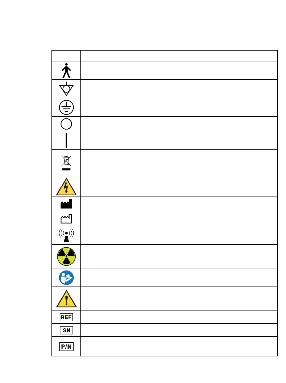
1.16 Symbols
This section describes the Symbols on this system.
Symbol Description
Type B Applied Part
Potential Equalization terminal
Protective Earth terminal
"OFF" (power)
"ON" (power)
Discard electrical and electronic equipment separately from standard
waste. Send decommissioned material to Hologic or contact your service
representative.
Warning Electricity
Manufacturer
Date of Manufacture
This system transmits radio frequency (RF) energy (non-ionizing
radiation)
Caution—Radiation
Follow instructions for use
Caution
Catalog number
Serial number
Part number
3Dimensions System User Guide
Chapter 1: Introduction
Page 10 MAN-05085-002 Revision 002
DRAFT Preview Copy-Generated May 30, 2018
1.17 Descriptions of Warnings, Cautions, and Notes
Descriptions of Warnings, Cautions, and Notes used in this manual:
WARNING!
The procedures that you must follow accurately to prevent possible
dangerous or fatal injury.
Warning:
The procedures that you must follow accurately to prevent injury.
Caution:
The procedures that you must follow accurately to prevent damage to equipment,
loss of data, or damage to files in software applications.
Note
Notes show additional information.
1.18 Document Conventions
When prompted to add text, enter the text printed in monospaced font exactly as
shown.
3Dimensions System User Guide
Chapter 2: General Information
MAN-05085-002 Revision 002 Page 11
DRAFT Preview Copy-Generated May 30, 2018
2: General Information
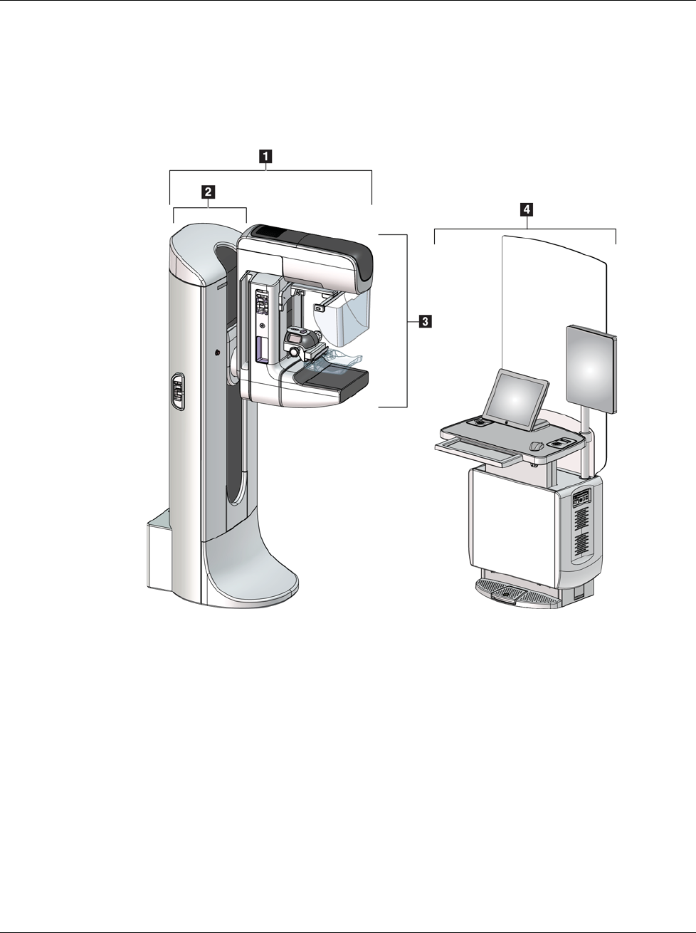
2.1 System Overview
Figure 1: 3Dimensions™ System
Figure Legend
1. Tubestand (Gantry and C-arm)
2. Gantry
3. C-arm (Tube Arm and Compression Arm)
4. Universal Acquisition Workstation
Chapter 2
3Dimensions System User Guide
Chapter 2: General Information
Page 12 MAN-05085-002 Revision 002
DRAFT Preview Copy-Generated May 30, 2018
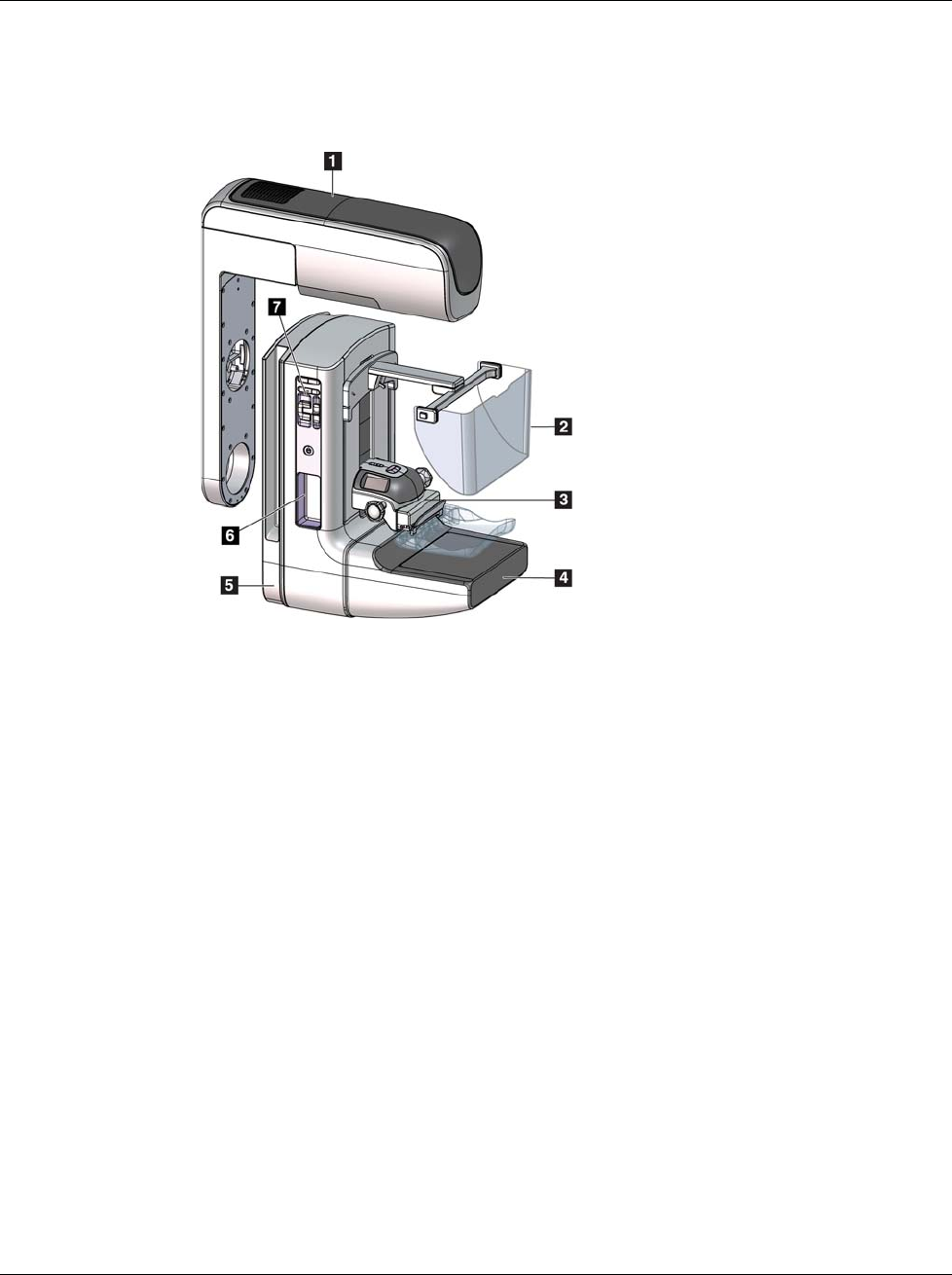
2.1.1 C-Arm Overview
Figure 2: C-arm Overview
Figure Legend
1. Tube Arm
2. Patient Face Shield
3. Compression Device
4. Image Receptor
5. Compression Arm
6. Patient Handle
7. C-arm Control Panel

3Dimensions System User Guide
Chapter 2: General Information
MAN-05085-002 Revision 002 Page 13
DRAFT Preview Copy-Generated May 30, 2018
2.2 Safety Information
Read and understand this manual before you use the system. Keep the manual available
during the patient procedures.
Always follow all the instructions in this manual. Hologic does not accept the
responsibility for injury or damage from incorrect system operation. Hologic can
schedule training at your facility.
The system has protective devices, but the Technologist must understand how to safely
use the system. The Technologist must remember the health hazards of x rays.
2.3 Warnings and Precautions
This system is classified as CLASS I, TYPE B APPLIED PART, IPX0, permanently
connected equipment, continuous operation with short term loading per IEC 60601-1.
There are no special provisions to protect the system from flammable anesthetics or
ingress of liquids.
WARNING!
Risk of electric shock. Only connect this equipment to supply mains
with Protective Earth.
WARNING!
For North American electrical safety requirements, use a Hospital
Grade receptacle to supply a correct Ground.
WARNING!
Electrical equipment used near flammable anesthetics can cause an
explosion.
WARNING!
To correctly isolate the system, attach only approved accessories or
options to the system. Only approved personnel can change the
connections.

3Dimensions System User Guide
Chapter 2: General Information
Page 14 MAN-05085-002 Revision 002
DRAFT Preview Copy-Generated May 30, 2018
WARNING!
Keep a 1.5 meter safe distance between the patient and any non-patient
devices.
Do not install non-patient system components (like the Workflow
Manager, a diagnostic review workstation, or a hard copy printer) in
the Patient Area.
WARNING!
Only trained Service Engineers authorized through Hologic can open
any of the panels. This system contains lethal voltages.
WARNING!
The user must correct problems before the system is used. Contact an
approved service representative for preventive maintenance.
WARNING!
After power failure, remove the patient from the system before you
apply power.
Warning:
This device contains dangerous material. Send decommissioned material to
Hologic or contact your service representative.
Warning:
C-arm movement is motorized.
Warning:
You increase the patient dose to high levels when you increase the AEC
exposure adjustment. You increase the image noise or decrease image quality
when you decrease the AEC exposure adjustment.
Warning:
Control the access to the equipment according to local regulations for
radiation protection.

3Dimensions System User Guide
Chapter 2: General Information
MAN-05085-002 Revision 002 Page 15
DRAFT Preview Copy-Generated May 30, 2018
Warning:
The disk drives installed in this system are a Class I Laser Product. Prevent
direct exposure to the beam. Hidden laser radiation exists if the case to a disk
drive is open.
Warning:
The bar code scanner installed in this system is a Class II Laser Product.
Prevent direct exposure to the beam. Hidden laser radiation exists if the cover
is opened.
Warning:
Keep your full body behind the radiation shield during the exposure.
Warning:
Do not move the C-arm while the system retrieves the image.
Warning:
If a paddle touches possible infectious materials, contact your Infection
Control Representative to remove contamination from the paddle.
Warning:
Do not leave the patient unattended during the procedure.
Warning:
Keep the hands of the patient away from all buttons and switches at all times.
Warning:
Place each footswitch in a position where, when used, they remain in reach of
the Emergency Off Switches.
Warning:
Position the footswitches to prevent accidental operation by a patient or
wheelchair.
Warning:
To prevent a higher radiation dose to the patient, only put approved
materials in the x-ray beam path.
3Dimensions System User Guide
Chapter 2: General Information
Page 16 MAN-05085-002 Revision 002
DRAFT Preview Copy-Generated May 30, 2018
Warning:
This system can be dangerous to the patient and the user. Always follow the
safety precautions for x-ray exposures.
Warning:
For exposures except magnification case studies, always use the Face Shield.
Warning:
The Face Shield does not protect the patient from radiation.
Warning:
Risk of entrapment. Make sure that the C-arm has 50 cm (20 inches) of
clearance to any object during C-arm rotation. Do not use Auto Rotation
when C-arm clearance is less than 50 cm (20 inches).
Caution:
The system is a medical device and not a normal computer. Only make approved
changes to the hardware or software. Install this device behind a firewall for network
security. The computer virus protection or network security for this medical device is
not supplied (for example, a computer firewall). The network security and anti-virus
provisions are the responsibility of the user.
Caution:
Do not turn off the Acquisition Workstation circuit breaker except in emergency. The
circuit breaker can turn off the Uninterruptible Power Supply (UPS) and risk data
loss.
Caution:
Risk of data loss. Do not put any magnetic media near or on devices that create any
magnetic fields.
Caution:
Do not use any heat source (like a heating pad) on the image receptor.
Caution:
To prevent possible damage from thermal shock to the Digital Image Receptor,
follow the recommended procedure to turn off the equipment.

3Dimensions System User Guide
Chapter 2: General Information
MAN-05085-002 Revision 002 Page 17
DRAFT Preview Copy-Generated May 30, 2018
Caution:
The display is calibrated for compliance to DICOM standards. Do not make any
brightness or contrast adjustments to the display.
Caution:
Use the least possible amount of cleaning fluids. The fluids must not flow or run.
Caution:
To prevent damage to the electronic components, do not use disinfectant sprays on
the system.
Note:
Hologic does not supply the Gantry power cable for some countries. If the power cable
is not supplied, the installed cable must meet the following requirements and all local
codes that apply: 3 conductor, 8 AWG (10 mm2) copper not more than 25 feet (7.62
meters) in length.
2.4 Emergency Off Switches
The Emergency Off switches remove the power from the Gantry and the Acquisition
Workstation Lift Mechanism (on the workstations that include that option). Do not
routinely use the Emergency Off switches to turn off the system.
Figure 3: Emergency Off Switch
Functionality
There are three Emergency Off switches, one on each
side of the Gantry and one on the Acquisition
Workstation.
1. To turn Off the Gantry and disable the Acquisition
Workstation Lift Mechanism, press any of the
Emergency Off switches.
2. To reset the Emergency Off switch, turn clockwise
approximately one-quarter turn until the switch
pops back out.

3Dimensions System User Guide
Chapter 2: General Information
Page 18 MAN-05085-002 Revision 002
DRAFT Preview Copy-Generated May 30, 2018
2.5 Interlocks
The 3Dimensions system has safety interlocks:
•C-arm vertical movement and rotation are disabled when compression force is
applied. A Service Engineer can configure the lockout force from 22 Newtons (5
pounds) to 45 Newtons (10 pounds).
•If the x-ray button or x-ray footswitch is released before the end of the exposure, the
exposure stops and an alarm message is displayed.
•When in Tomo mode, the system does not allow an exposure if the Grid is in the x-
ray field (Tomosynthesis option).
•Mirror and Filter position flags also prevent x rays when the Light Field Mirror or the
Filter Assembly is not correctly positioned.
2.6 Compliance
This section describes the mammography system compliance requirements and the
responsibilities of the manufacturer.
2.6.1 Compliance Requirements
The manufacturer has the responsibility for the safety, reliability, and performance of this
equipment with the following provisions:
•The electrical installation of the room meets all requirements.
•The equipment is used according to the User Guide.
•The assembly operations, extensions, adjustments, changes, or repairs are performed
only by authorized persons.
•The network and communication equipment is installed to meet IEC Standards. The
complete system (network and communications equipment and the mammography
system) must be in compliance with IEC 60601-1.
Caution:
Medical Electrical Equipment needs special precautions about EMC and must be
installed, put into service and used according to the EMC information provided.
Caution:
Portable and mobile RF communications can affect medical electrical equipment.
Caution:
The use of unauthorized accessories and cables can result in increased emissions or
decreased immunity. To keep the isolation quality for the system, attach only
approved Hologic accessories or options to the system.

3Dimensions System User Guide
Chapter 2: General Information
MAN-05085-002 Revision 002 Page 19
DRAFT Preview Copy-Generated May 30, 2018
Caution:
The Medical Electrical (ME) Equipment or ME System should not be used adjacent to
or stacked with other equipment. If adjacent or stacked use is necessary, make sure
that the ME Equipment or ME System operates correctly in this configuration.
Caution:
This system is intended for use by healthcare professionals only. This system may
cause radio interference or may disrupt the operation of nearby equipment. It may be
necessary to take mitigation measures, such as re-orienting or relocating the
equipment or shielding the location.
Caution:
Changes or modifications not expressly approved by Hologic could void your
authority to operate the equipment.
Caution:
This equipment has been tested and found to comply with the limits for a Class A
digital device, pursuant to part 15 of the FCC Rules. These limits are designed to
provide reasonable protection against harmful interference when the equipment is
operated in a commercial environment. This equipment generates, uses, and can
radiate radio frequency energy and, if not installed and used in accordance with the
instruction manual, may cause harmful interference to radio communications.
Operation of this equipment in a residential area is likely to cause harmful
interference in which case the user will be required to correct the interference at his
own expense.
Caution:
Based on ENCLOSURE PORT IMMUNITY to RF WIRELESS COMMUNICATIONS
EQUIPMENT test level per IEC 60601-1-2 ed. 4, this device shows susceptibility to
GMRS 460, FRS 460 transmission frequency. Provide a minimum separation of 30 cm
between GMRS and FRS radios and the system.
Caution:
This device complies with Industry Canada licence-exempt RSS standard(s).
Operation is subject to the following two conditions: (1) this device may not cause
interference, and (2) this device must accept any interference, including interference
that may cause undesired operation of the device.

3Dimensions System User Guide
Chapter 2: General Information
Page 20 MAN-05085-002 Revision 002
DRAFT Preview Copy-Generated May 30, 2018
2.6.2 Compliance Statements
The manufacturer states this device is made to meet the following requirements:
Medical – Applied electromagnetic radiation equipment as to electrical shock, fire and
mechanical hazards only in accordance with ANSI/AAMI ES60601-1 (2005) and
CAN/CSA-C22.2 No. 60601-1 (2008)
•CAN/CSA - ISO 13485-03 Medical Devices – Quality Management Systems –
Requirements for Regulatory Purposes (Adopted ISO 13485:2003 second edition,
2003-07-15)
•CAN/CSA C22.2 NO. 60601-1-08 Medical Electrical Equipment – Part 1: General
Requirements for Basic Safety and Essential Performance (Adopted IEC 60601-1:2005,
third edition, 2005-12), includes Corrigendum 1:2011
•EN 60601-1:2006 Medical Electrical Equipment. General Requirements for Basic
Safety and Essential Performance
•ETSI EN 300 330-1: V1.3.1, and ETSI EN 300 330-2: V1.5.1: 2006—Electromagnetic
compatibility and Radio spectrum Matters (ERM); Short Range Devices (SRD); Radio
equipment in the frequency range 9 kHz to 25 MHz and inductive loop systems in
the frequency range 9 kHz to 30 MHz
•ETSI EN 301 489-1: V1.6.1, and ETSI EN 301 489-3: V1.8.1: 2008—Electromagnetic
compatibility and Radio spectrum Matters (ERM); ElectroMagnetic Compatibility
(EMC) standard for radio equipment and services
•FCC, 47 CFR Part 15, Subpart C, Section 15.225: 2009
•FDA, 21 CFR [Parts 820, 900 and 1020]
•IEC 60601-1 Ed. 3.0:2005 Medical Electrical Equipment – Part 1: General
Requirements for Basic Safety and Essential Performance
•IEC 60601-1-2 Ed. 3.0:2007 Medical Electrical Equipment – Part 1-2: General
Requirements for Basic Safety and Essential Performance - Collateral Standard:
Electromagnetic Compatibility – Requirements and Tests
•IEC 60601-1-3 Ed. 2.0:2008 Medical Electrical Equipment – Part 1-3: General
Requirements for Basic Safety and Essential Performance –Collateral Standard:
Radiation Protection in Diagnostic X-Ray Equipment
•IEC 60601-2-28 Ed. 2.0:2010 Medical Electrical Equipment - Part 2-28: Particular
Requirements for the Basic Safety and Essential Performance of X-ray Tube
Assemblies for Medical Devices
•IEC 60601-2-45 Ed. 3.0:2011 Medical Electrical Equipment – Part 2-45: Particular
Requirements for Basic Safety and Essential Performance of Mammographic X-Ray
Equipment and Mammographic Stereotactic Devices
•RSS-210: Issue 7, 2007 Radio Standards Specification Low-power License-exempt
Radiocommunication Devices: Category I Equipment
•ANSI/AAMI ES60601-1:2005 (IEC 60601-1:2005, MOD) Medical Electrical Equipment,
Part 1: General Requirements for Basic Safety and Essential Performance, includes
amendment (2010)
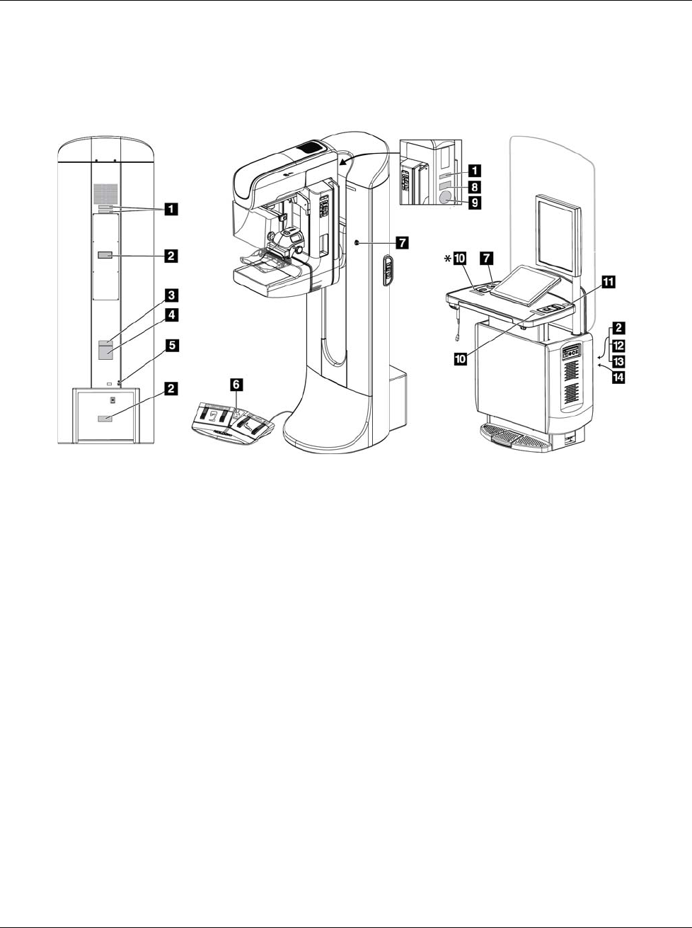
3Dimensions System User Guide
Chapter 2: General Information
MAN-05085-002 Revision 002 Page 21
DRAFT Preview Copy-Generated May 30, 2018
2.7 Label Locations
Figure 4: Label Locations
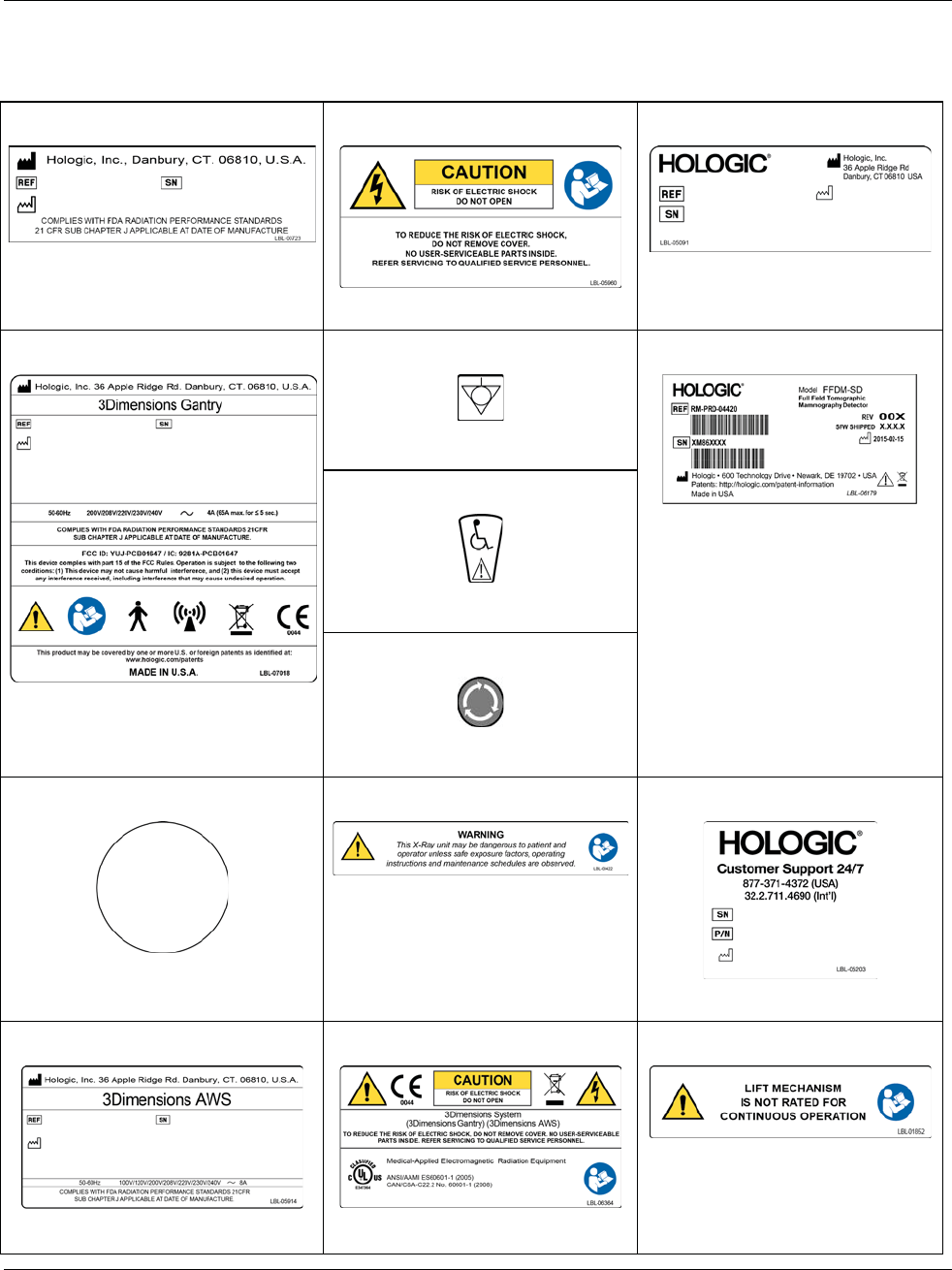
3Dimensions System User Guide
Chapter 2: General Information
Page 22 MAN-05085-002 Revision 002
DRAFT Preview Copy-Generated May 30, 2018
Table 1: System Labels
1
Serialized Device
2
Electrical Shock Warning
3
System Model
4
Gantry Nameplate
5
Potential Equalization Terminal
8
Tomographic Mammography
Detector
6
Wheelchair Warning for Footswitch
7
Emergency Stop Switch
9
Vendor-supplied X-ray Tube Serial
Number
10
X-ray Device Warning
11
Technical Support Contact
12
Acquisition Workstation Nameplate
13
Compliance
14
Acquisition Workstation Lift Limit
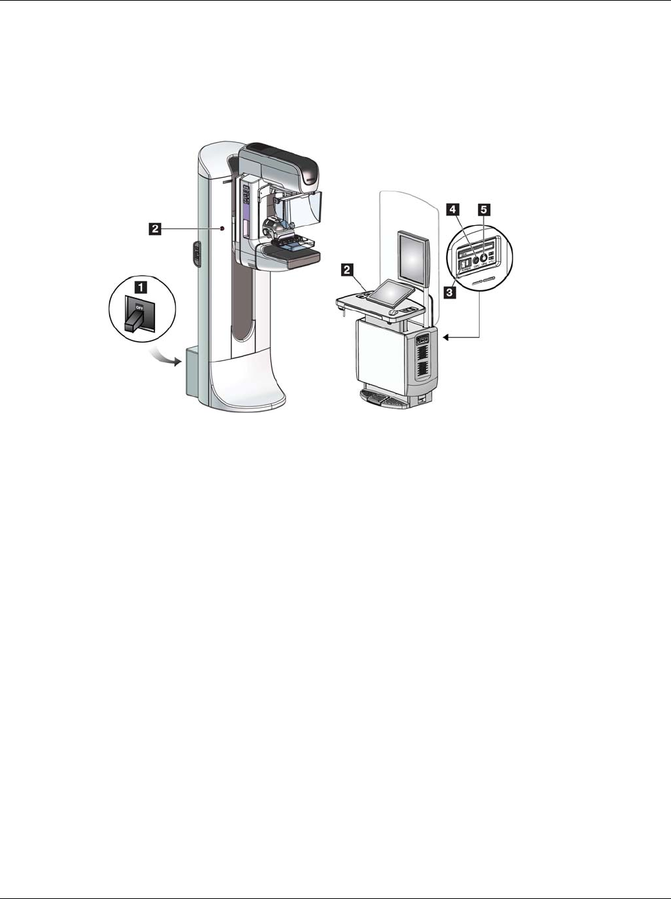
3Dimensions System User Guide
Chapter 3: System Controls and Indicators
MAN-05085-002 Revision 002 Page 23
DRAFT Preview Copy-Generated May 30, 2018
3: System Controls and Indicators
3.1 System Power Controls
Figure 5: System Power Controls
Figure Legend
1. Gantry Power Circuit Breaker
2. Emergency Off Switch (two on the Gantry, one on the
Acquisition Workstation)
3. Acquisition Workstation Power Switch
4. Computer Power On/Reset Button
5. Uninterruptible Power Supply (UPS) Power Button
Chapter 3
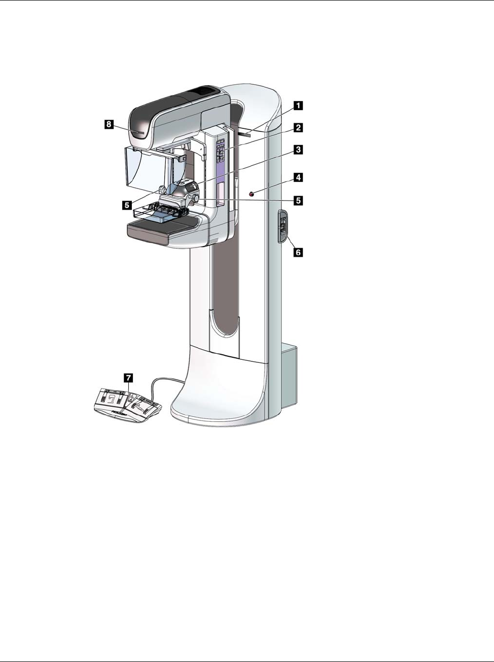
3Dimensions System User Guide
Chapter 3: System Controls and Indicators
Page 24 MAN-05085-002 Revision 002
DRAFT Preview Copy-Generated May 30, 2018
3.2 Tubestand Controls and Indicators
Figure 6: Tubestand Controls and Indicators
Figure Legend
1. Rotation Angle Displays (each side)
2. C-arm Control Panels (each side)
3. Compression Device
4. Emergency Off Switches (each side)
5. Compression Handwheels
6. Gantry Control Panels (each side)
7. Footswitch
8. Tubehead Display
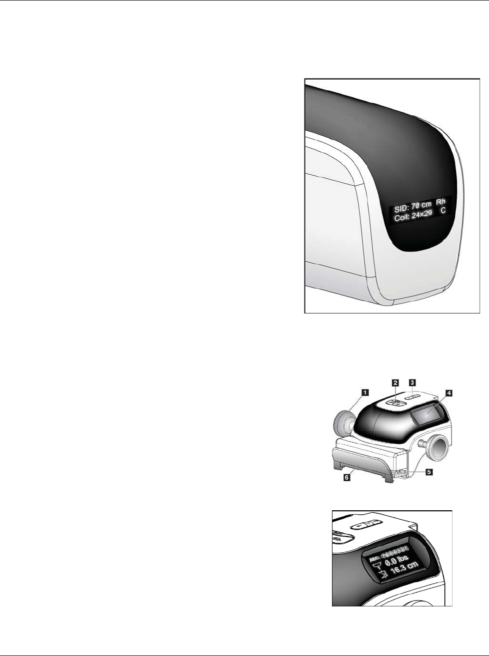
3Dimensions System User Guide
Chapter 3: System Controls and Indicators
MAN-05085-002 Revision 002 Page 25
DRAFT Preview Copy-Generated May 30, 2018
3.2.1 Tubehead Display
The Tubehead Display shows:
xSID
xFilter Type
xCollimator Setting
xPaddle Position
Figure 7: Tubehead Display
3.2.2 Compression Device Controls and Display
Figure Legend
1. Manual Compression Handwheels
2. Paddle Shift Buttons
3. AEC Sensor Buttons
4. Compression Device Display
5. FAST Compression Mode Slide
6. Paddle Clamp
Figure 8: Compression Device
The Compression Device Display shows:
xAEC Sensor Position
xCompression Force (displays 0.0
when force is less than 4 pounds)
xCompression Thickness
xAngle of the C-arm after rotation
(for 5 seconds)
Figure 9: Compression Device Display
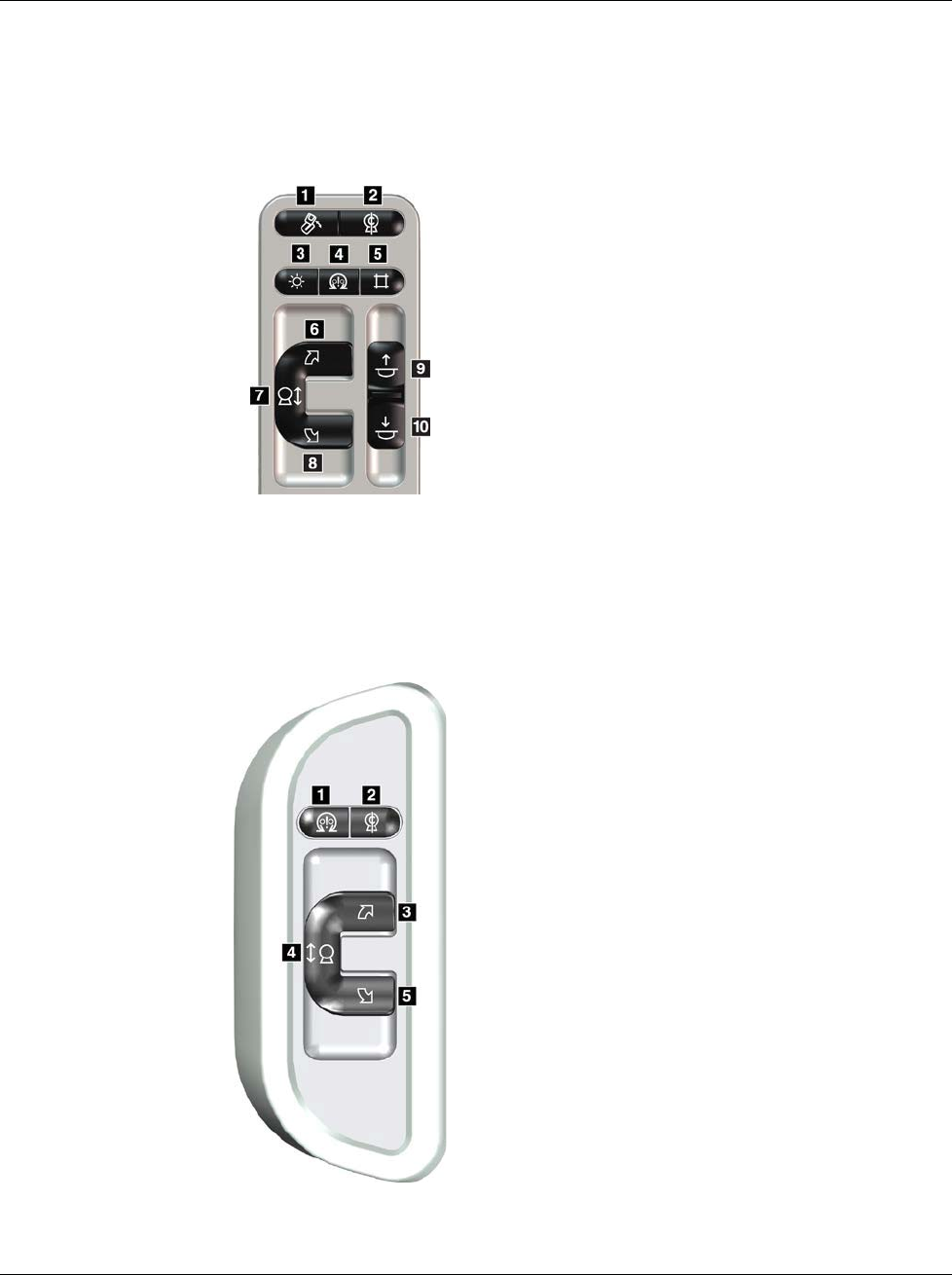
3Dimensions System User Guide
Chapter 3: System Controls and Indicators
Page 26 MAN-05085-002 Revision 002
DRAFT Preview Copy-Generated May 30, 2018
3.2.3 C-Arm Control Panels
There is a C-arm control panel on both the left side and right side of the C-arm. These
buttons provide the Collimator and C-arm functions.
Figure 10: C-arm Control Panel
Figure Legend
1. MLO Rotation
2. C-arm Zero
3. Light Field Lamp
4. Motor Enable
5. Collimator Override
6. Clockwise C-arm Rotation
7. C-arm Up and Down
8. Counterclockwise C-arm Rotation
9. Compression Up
10. Compression Down
3.2.4 Gantry Control Panels
Control panels on the Gantry provide additional access to C-arm functions. There is a C-
arm control panel on both the left side and right side of the Gantry.
Figure 11: Gantry Control Panel
Figure Legend
1. Motor Enable
2. C-arm Zero
3. Clockwise C-arm Rotation
4. C-arm Up and Down
5. Counterclockwise C-arm Rotation
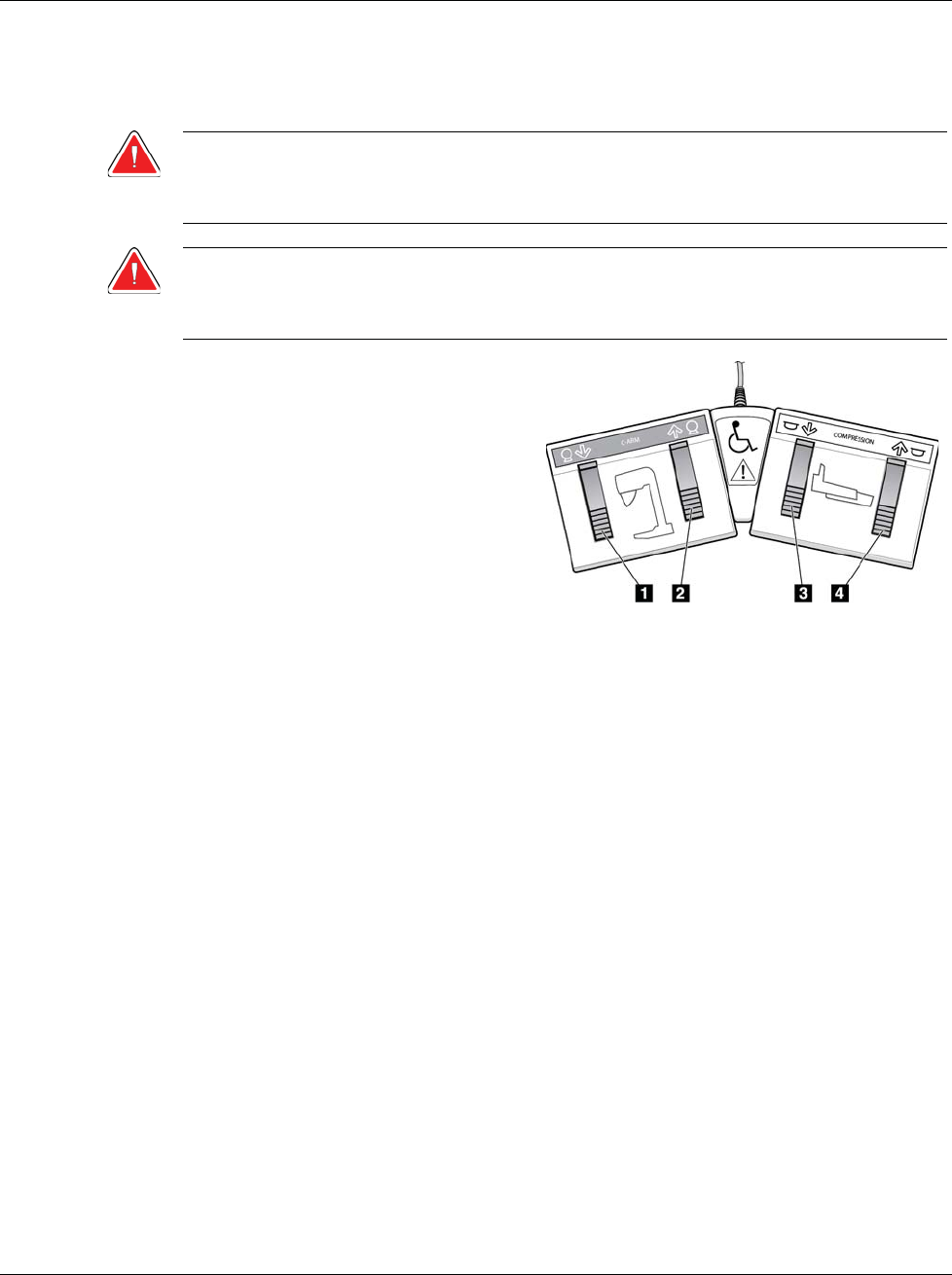
3Dimensions System User Guide
Chapter 3: System Controls and Indicators
MAN-05085-002 Revision 002 Page 27
DRAFT Preview Copy-Generated May 30, 2018
3.2.5 Dual Function Footswitch
Warning:
Place each footswitch in a position where, when used, they remain in reach of
the Emergency Off Switches.
Warning:
Position the footswitches to prevent accidental operation by a patient or
wheelchair.
To use the footswitch:
1. Press the footswitch to actuate.
2. Release the switch to stop the
movement.
Figure Legend
1. C-arm Down
2. C-arm Up
3. Compression Down
4. Compression Up
Figure 12: Dual Function Footswitch
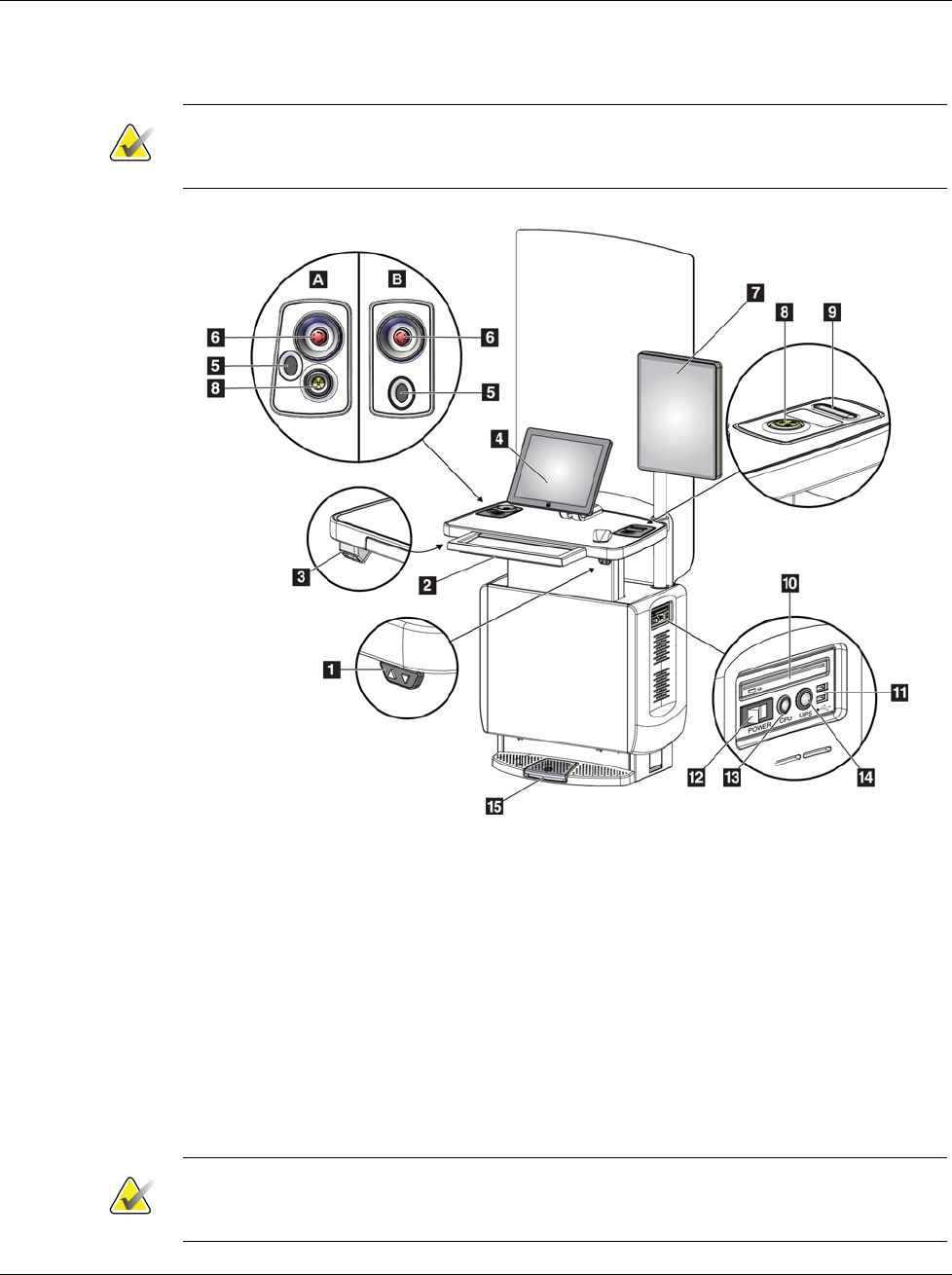
3Dimensions System User Guide
Chapter 3: System Controls and Indicators
Page 28 MAN-05085-002 Revision 002
DRAFT Preview Copy-Generated May 30, 2018
3.3 Universal Acquisition Workstation Controls and Displays
Note
Hologic configures some systems to meet specific requirements. Your system
configuration may not have all the options and accessories included in this manual.
Figure 13: Universal Acquisition Workstation Controls and Displays
Figure Legend
1. Height Adjustment Switch
2. Keyboard (in drawer)
3. Bar Code Scanner
4. Control Monitor
5. Fingerprint Scanner*
6. Emergency Off Switch*
7. Image Display Monitor
8. X-ray Activation Button*
9. Compression Release Button
10. CD/DVD Drive
11. USB Ports
12. Acquisition Workstation Power Switch
13. Computer Power On/Reset Button
14. Uninterruptible Power Supply (UPS)
Power Button
15. X-ray Footswitch
*A = series II UAWS layout; B = series I UAWS layout
Note
The controls for the Universal Acquisition Workstation installed in a mobile
environment are the same as the controls for the Universal Acquisition Workstation.
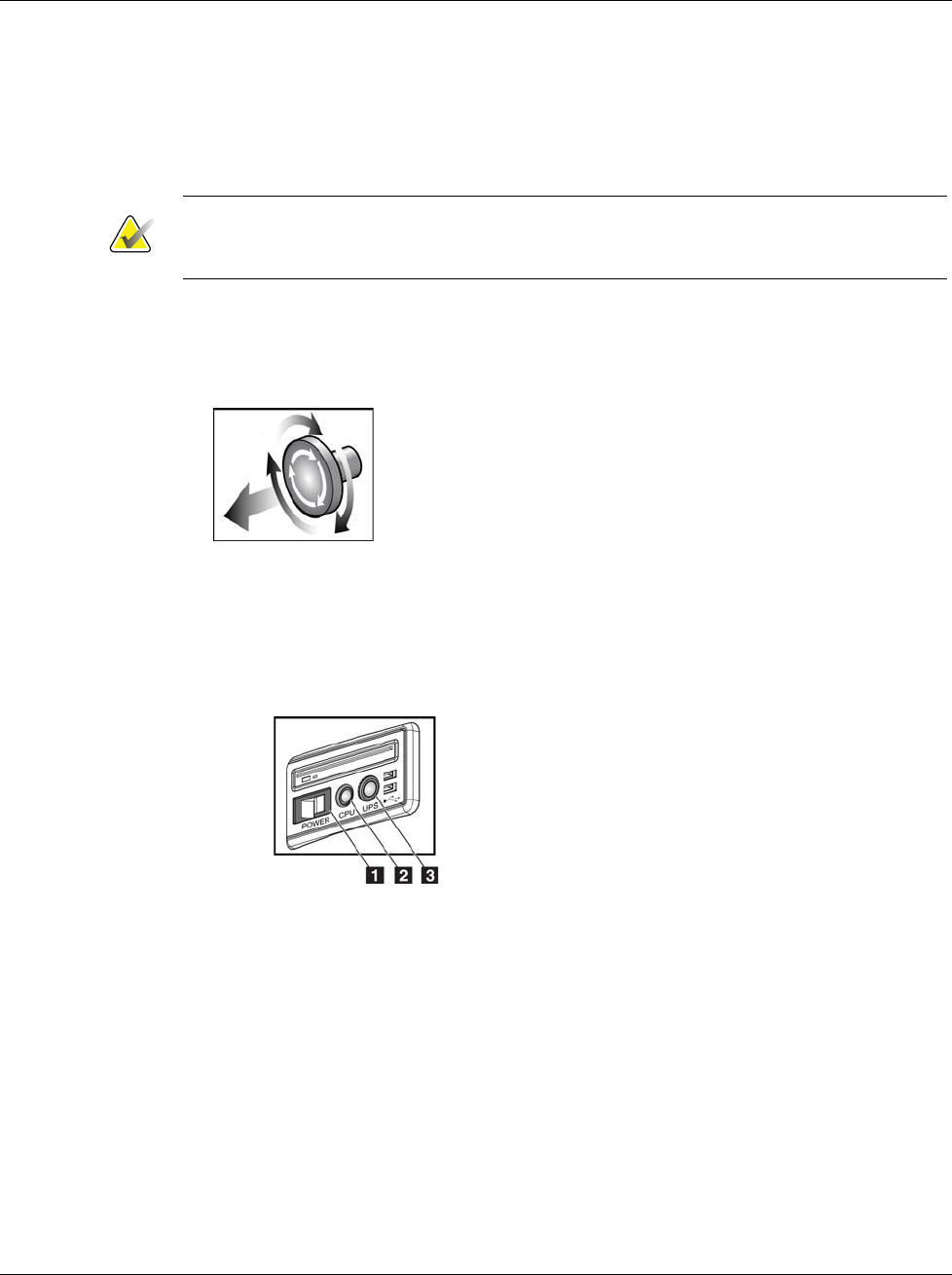
3Dimensions System User Guide
Chapter 4: Startup, Functional Tests, and Shutdown
MAN-05085-002 Revision 002 Page 29
DRAFT Preview Copy-Generated May 30, 2018
4: Startup, Functional Tests, and Shutdown
4.1 How to Start the System
Note
If the system remains on overnight, restart the system daily to guarantee best
performance.
1. Make sure that there are no obstructions to C-arm movement or to the view of the
Operator.
2. Make sure that all three Emergency Off switches are in the reset position (unpushed).
Figure 14: Turn to Reset the
Emergency Off Switches
3. Make sure that the Gantry circuit breaker is in the ON position.
4. If the UPS was turned OFF, press the UPS power button to apply power to the UPS
(see the following figure).
Figure 15: Universal Acquisition
Workstation Power Buttons
Figure Legend
1. Acquisition Workstation Power Switch
2. Computer Power On/Reset Button
3. UPS Power Button
5. Turn ON the Acquisition Workstation power switch (see the previous figure).
Chapter 4
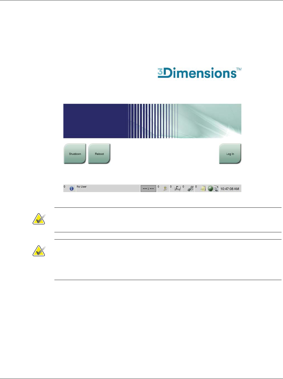
3Dimensions System User Guide
Chapter 4: Startup, Functional Tests, and Shutdown
Page 30 MAN-05085-002 Revision 002
DRAFT Preview Copy-Generated May 30, 2018
6. Press the computer power button (see the previous figure). The computer powers on
and the Startup screen opens on the Acquisition Workstation control monitor. The
Gantry then automatically powers on.
Figure 16: Startup Screen
Note
The Startup screen includes a Shutdown button that turns off the system, and a Reboot
button that restarts the system.
Note
The system can require between five minutes and fifteen minutes to prepare for image
acquisition. The wait time depends on the detector power configuration. A timer in the
Taskbar displays the wait time before the system is ready. Do not acquire clinical or QC
images unless the System Status Icon indicates that the system is Ready.
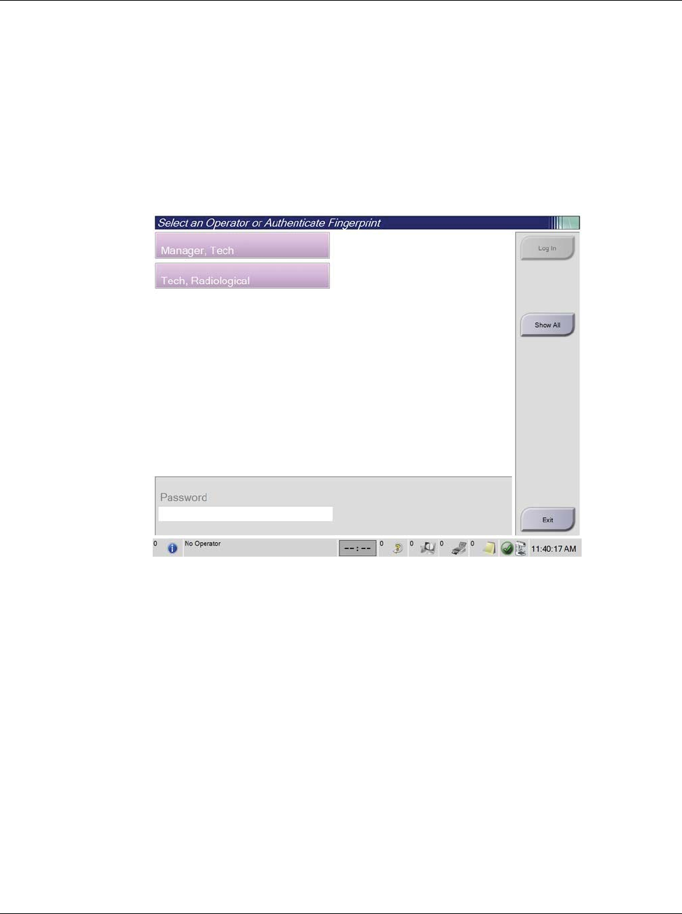
3Dimensions System User Guide
Chapter 4: Startup, Functional Tests, and Shutdown
MAN-05085-002 Revision 002 Page 31
DRAFT Preview Copy-Generated May 30, 2018
4.2 Log In
1. Select the Log In button on the Startup screen.
2. The Select an Operator (Log In) screen opens and shows a list of Manager and
Technologist user names. If necessary, select the Show All button to list the Service,
Applications, and Physicist user names.
3. Choose an operator by selecting the applicable user name.
Figure 17: Select an Operator (Log In) Screen
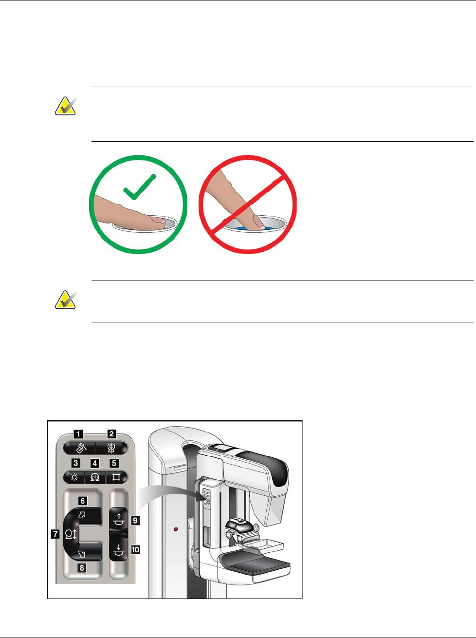
3Dimensions System User Guide
Chapter 4: Startup, Functional Tests, and Shutdown
Page 32 MAN-05085-002 Revision 002
DRAFT Preview Copy-Generated May 30, 2018
4. Type in your password and select Log In.
-OR-
Validate your fingerprint by pressing your finger in the fingerprint scanner.
Note
Most of the unique, repeatable fingerprint information is from the pad of the finger, not
the fingertip. Flat finger placement as shown in the left image results in fast and
accurate fingerprint identification.
Correct operation Incorrect operation
Note
If Quality Control tasks are due, the Select Function to Perform screen opens. You can
perform the quality tasks or you can select Skip.
4.3 Perform the Functional Tests
To make sure that the controls operate correctly, do the Functional Tests as part of your
monthly visual checklist. Make sure that all buttons work correctly (Gantry and C-arm
control panels, left and right sides).
Figure 18: C-arm Control Panel (left side shown)
Figure Legend
1. MLO Rotation
2. C-arm Zero
3. Light Field Lamp
4. Motor Enable
5. Collimator Override
6. Clockwise C-arm Rotation
7. C-arm Up and Down
8. Counterclockwise C-arm Rotation
9. Compression Up
10. Compression Down
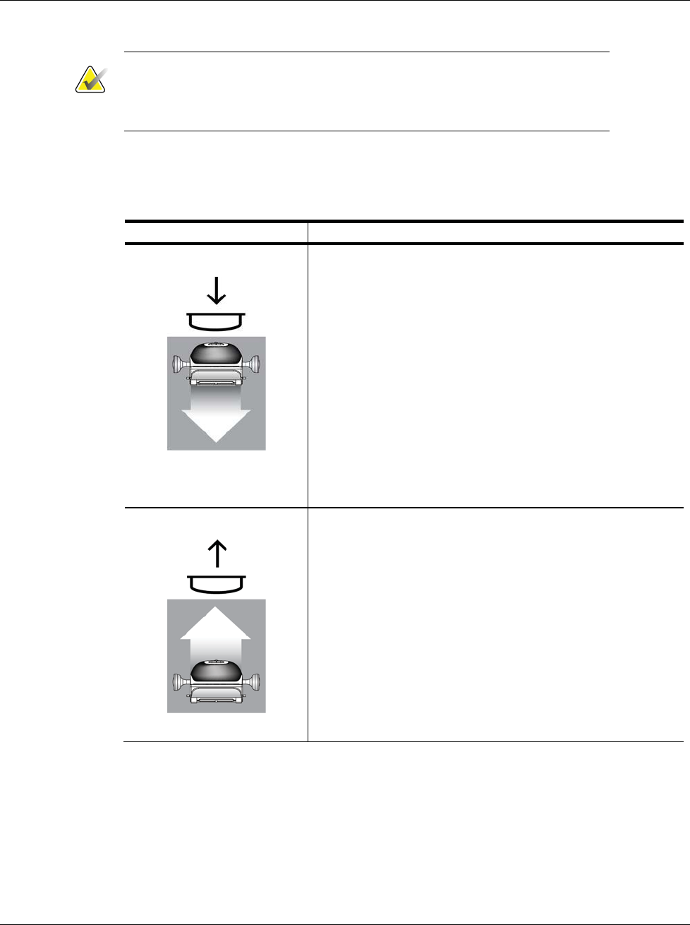
3Dimensions System User Guide
Chapter 4: Startup, Functional Tests, and Shutdown
MAN-05085-002 Revision 002 Page 33
DRAFT Preview Copy-Generated May 30, 2018
Note
C-arm vertical movement and rotation are disabled when compression force
is applied. A Service Engineer can configure the lockout force from 22
Newtons (5 pounds) to 45 Newtons (10 pounds).
4.3.1 Compression Functional Tests
Table 2: Compression Tests
Function Functional Test
Compression Down
Press a Compression Down button:
xThe compression brake engages.
xThe light field lamp illuminates.
xThe compression device lowers.
Note… When you press the Compression Down button, the
compression brake remains engaged until the Compression
Release button is pressed.
Compression down movement stops:
xWhen you release the button.
xWhen you reach the Down Force limit.
xWhen you reach the lower travel limit.
Compression Up
Press a Compression Up button:
xThe Compression Device moves toward the top.
Note… The Compression Up button does NOT release the
Compression Brake.
Compression up movement automatically stops:
xWhen you release the button.
xWhen you reach the upper travel limit.
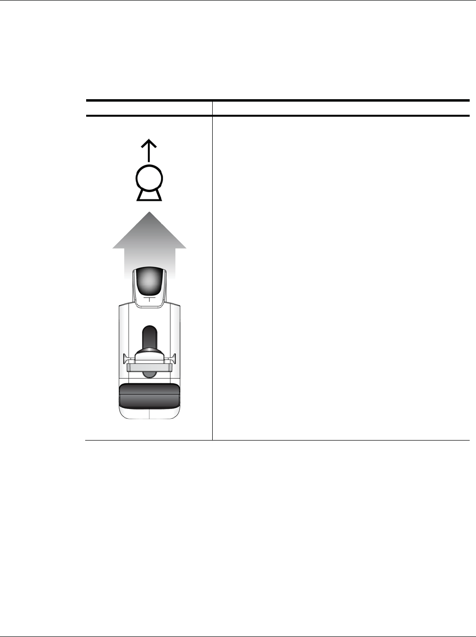
3Dimensions System User Guide
Chapter 4: Startup, Functional Tests, and Shutdown
Page 34 MAN-05085-002 Revision 002
DRAFT Preview Copy-Generated May 30, 2018
4.3.2 C-Arm Movement Functional Tests
C-Arm Up and Down Movement
Table 3: C-arm Up and Down Movement
Function Functional Test
C-arm Up
Press the C-arm Up button.
xC-arm movement stops when the button is
released.
xC-arm movement stops when the C-arm reaches
the upper travel limit.
xC-arm vertical movement and rotation are
disabled when compression force is applied. A
Service Engineer can configure the lockout force
from 22 Newtons (5 pounds) to 45 Newtons (10
pounds).
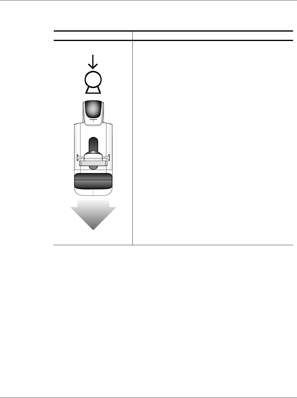
3Dimensions System User Guide
Chapter 4: Startup, Functional Tests, and Shutdown
MAN-05085-002 Revision 002 Page 35
DRAFT Preview Copy-Generated May 30, 2018
Table 3: C-arm Up and Down Movement
Function Functional Test
C-arm Down
Press the C-arm Down button.
xC-arm movement stops when the button is
released.
xC-arm movement stops when the C-arm reaches
the lower travel limit.
xC-arm vertical movement and rotation are
disabled when compression force is applied. A
Service Engineer can configure the lockout force
from 22 Newtons (5 pounds) to 45 Newtons (10
pounds).
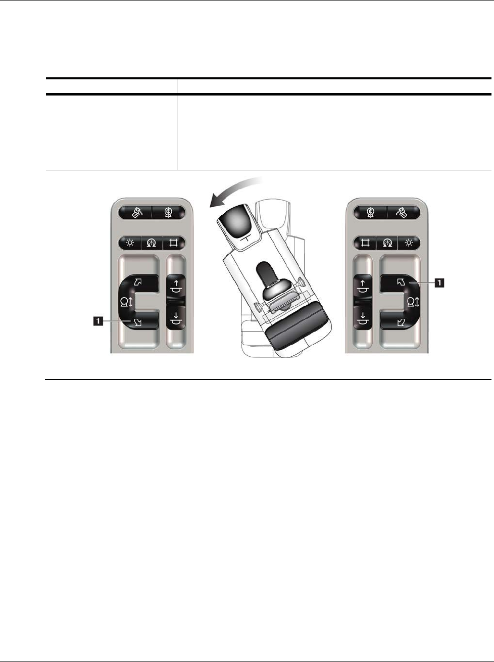
3Dimensions System User Guide
Chapter 4: Startup, Functional Tests, and Shutdown
Page 36 MAN-05085-002 Revision 002
DRAFT Preview Copy-Generated May 30, 2018
C-Arm Rotation
Table 4: C-arm Counterclockwise Rotation
Function Functional Test
Counterclockwise C-arm
Rotation
Press the Counterclockwise C-arm Rotation button (item 1) to start
counterclockwise C-arm rotation. C-arm movement stops when the
switch is released. To fine-tune the C-arm rotation in one degree
segments, hold the button down for a second, then let go quickly.
Repeat as necessary.
Left Panel Right Panel
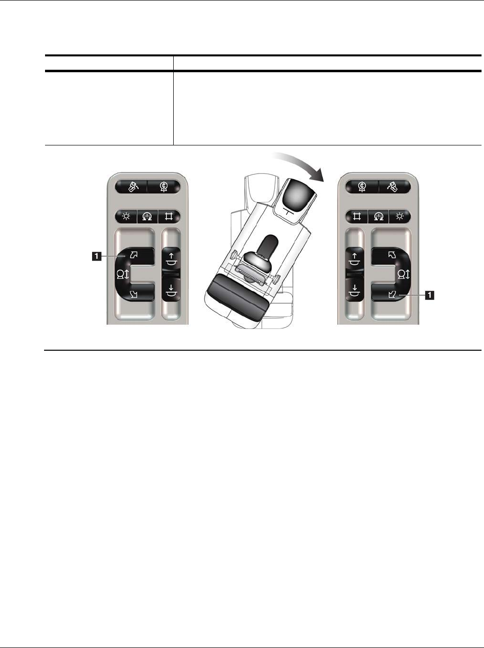
3Dimensions System User Guide
Chapter 4: Startup, Functional Tests, and Shutdown
MAN-05085-002 Revision 002 Page 37
DRAFT Preview Copy-Generated May 30, 2018
Table 5: C-arm Clockwise Rotation
Function Functional Test
Clockwise C-arm Rotation Press the Clockwise C-arm Rotation button (item 1) to start
clockwise C-arm rotation. C-arm movement stops when the switch
is released. To fine-tune the C-arm rotation in one degree segments,
hold the button down for a second, then let go quickly. Repeat as
necessary.
Left Panel Right Panel
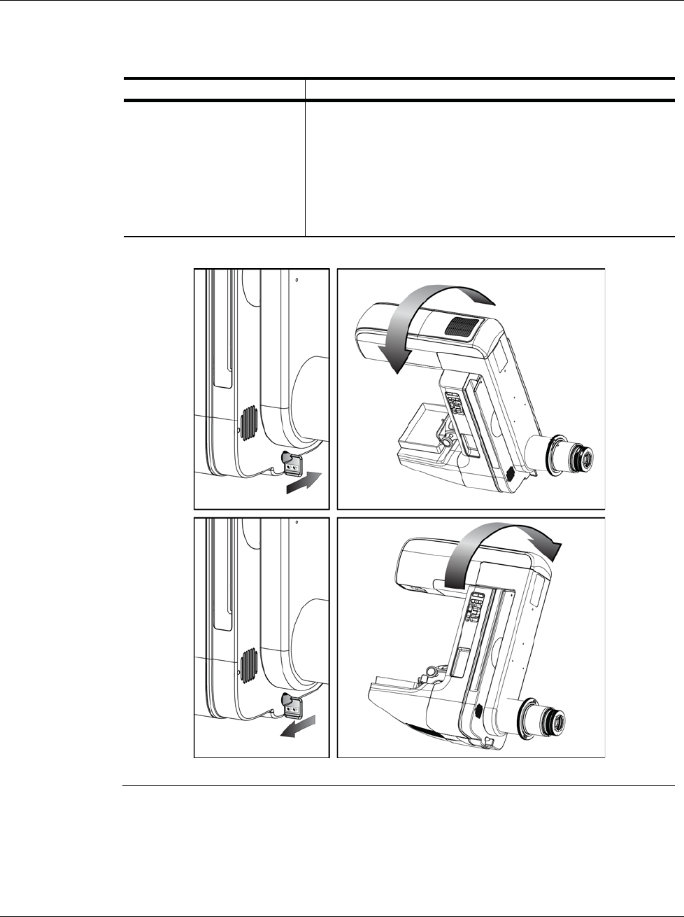
3Dimensions System User Guide
Chapter 4: Startup, Functional Tests, and Shutdown
Page 38 MAN-05085-002 Revision 002
DRAFT Preview Copy-Generated May 30, 2018
Table 6: C-arm Rotation Switch
Function Functional Test
C-arm Rotation Switch Push the C-arm Rotation switch away from you to move
the C-arm toward you.
Pull the C-arm Rotation switch toward you to move the
C-arm away from you.
C-arm movement stops when the switch is released.
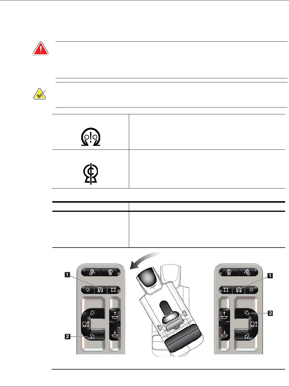
3Dimensions System User Guide
Chapter 4: Startup, Functional Tests, and Shutdown
MAN-05085-002 Revision 002 Page 39
DRAFT Preview Copy-Generated May 30, 2018
C-Arm Automatic Rotation (Auto-Rotate)
Warning:
Risk of entrapment. Make sure that the C-arm has 50 cm (20 inches) of
clearance to any object during C-arm rotation. Do not use Auto Rotation
when C-arm clearance is less than 50 cm (20 inches).
Note
To stop the C-arm automatic rotation movement, press any button or the Emergency
Stop switch.
Motor Enable Press the Motor Enable button and a Rotation button at
the same time to enable auto-rotation movement
clockwise or counterclockwise.
C-arm Zero Press the Motor Enable button and the C-arm Zero
button at the same time. Release the buttons. The machine
beeps and the C-arm returns automatically to the zero
position.
Table 7: Automatic C-arm Counterclockwise Rotation
Function Functional Test
Automatic
Counterclockwise C-arm
Rotation
Press the Motor Enable button (item 1) and the
Counterclockwise C-arm Rotation button (item 2) at the
same time. Release the buttons. The machine beeps and
the C-arm moves automatically counterclockwise.
Left Panel Right Panel
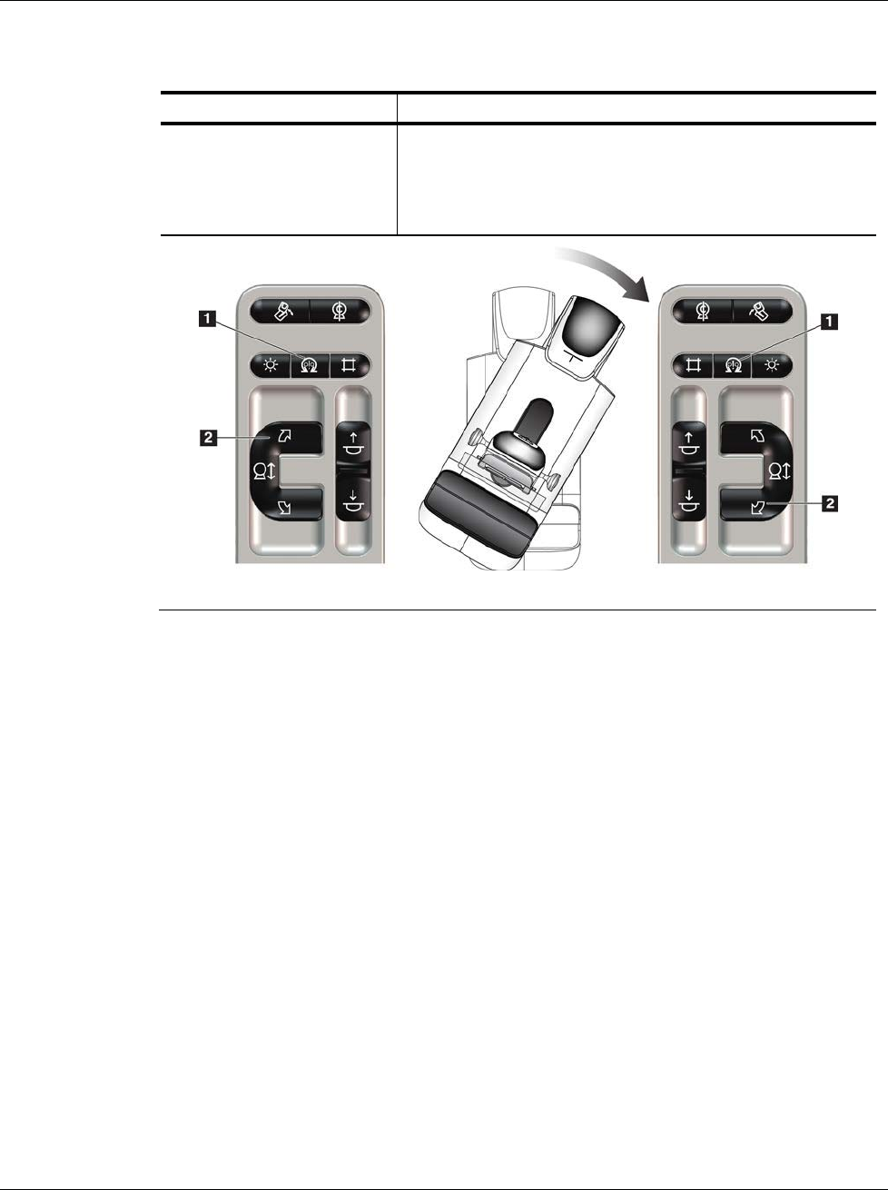
3Dimensions System User Guide
Chapter 4: Startup, Functional Tests, and Shutdown
Page 40 MAN-05085-002 Revision 002
DRAFT Preview Copy-Generated May 30, 2018
Table 8: Automatic C-arm Clockwise Rotation
Function Functional Test
Automatic Clockwise C-
arm Rotation
Press the Motor Enable button (item 1) and the
Clockwise C-arm Rotation button (item 2) at the same
time. Release the buttons. The machine beeps and the C-
arm moves automatically clockwise.
Left Panel Right Panel
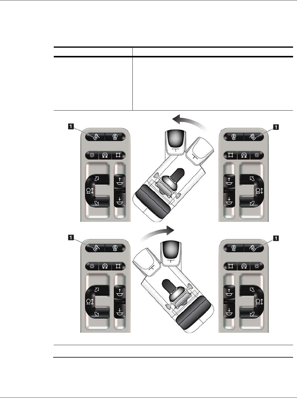
3Dimensions System User Guide
Chapter 4: Startup, Functional Tests, and Shutdown
MAN-05085-002 Revision 002 Page 41
DRAFT Preview Copy-Generated May 30, 2018
MLO Automatic Rotation
Table 9: Automatic MLO Rotation
Function Functional Test
Automatic Tubehead
Rotation to Zero Position
Position the C-arm at an angle greater than 15 degrees.
Press the MLO Rotation button (item 1). The Tubehead
moves automatically to the zero position. The
Compression Arm stays in its angled position. Press the
MLO Rotation button again to return the Tubehead to its
original position.
Left Panel Right Panel
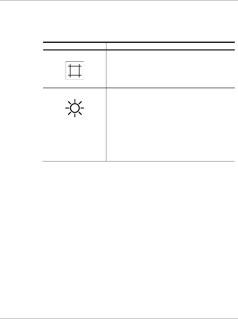
3Dimensions System User Guide
Chapter 4: Startup, Functional Tests, and Shutdown
Page 42 MAN-05085-002 Revision 002
DRAFT Preview Copy-Generated May 30, 2018
4.3.3 Collimation
Table 10: C-arm Collimation
Function Functional Test
Collimator Override The Collimator Override button changes the collimation
through the different x-ray fields.
Press the Light Field Lamp button to show the x-ray field,
then press the Collimator Override button to select an x-
ray field.
Light Field Lamp For compression paddles: Press the Light Field Lamp
button to see the x-ray field for two minutes.
For localization paddles: Press the Light Field Lamp
button to see the x-ray field for the configured amount of
time. The default time for biopsy or needle localization
paddles is ten minutes.
Press the Light Field Lamp button again to turn off the
light field lamp.
The light field lamp automatically illuminates with the
start of the Compression Down movement.
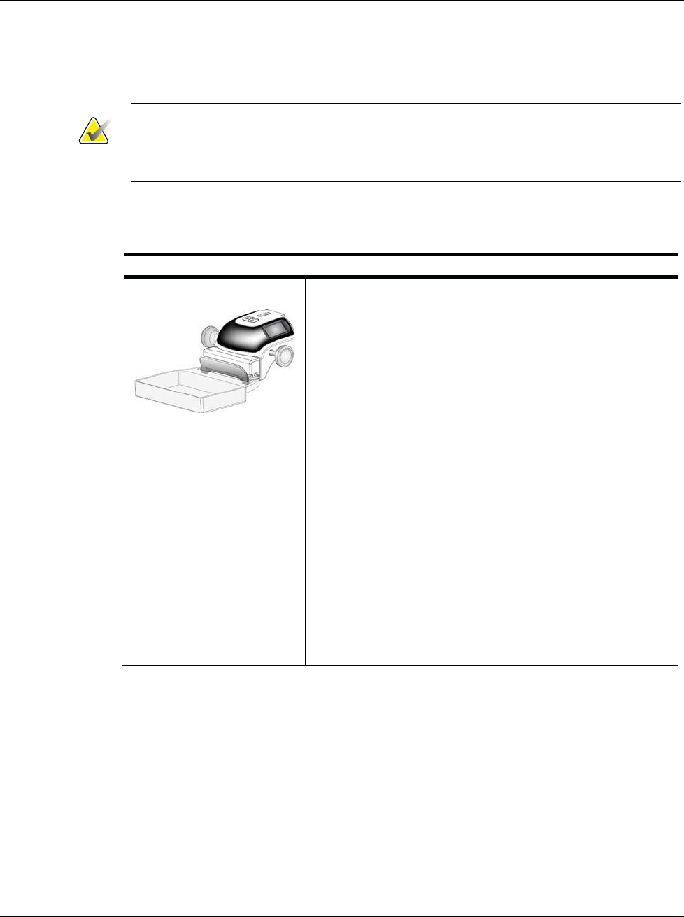
3Dimensions System User Guide
Chapter 4: Startup, Functional Tests, and Shutdown
MAN-05085-002 Revision 002 Page 43
DRAFT Preview Copy-Generated May 30, 2018
4.3.4 Shifting Paddles
Note
Most paddles can be used with the Shifting Paddle function. The large 24 x 29 cm
Frameless Screening Paddle, the large 24 x 29 cm SmartCurve™ system paddle, and the
Magnification paddles are not compatible with the Shifting Paddle function.
Use the 18 x 24 cm Frameless Screening Paddle to test the Shifting Paddle function.
Table 11: Shifting Paddle
Function Functional Test
Paddle Shift
The 18 x 24 cm Screening Paddle moves approximately 2.5
cm into the left, center, or right position. While
compression is applied, you cannot move the paddle. The
collimator is programmed to follow the position of the
paddle.
To test this function:
1. Install the 18 x 24 cm paddle in the Compression
Device.
2. Select a view.
3. Use the Paddle Shift buttons on the Procedure screen
to override the position.
4. Verify that the paddle automatically moves to the new
position.
5. Turn on the light field lamp.
6. Confirm that the collimator position matches the
paddle position.
7. Repeat this procedure for the other paddle positions.
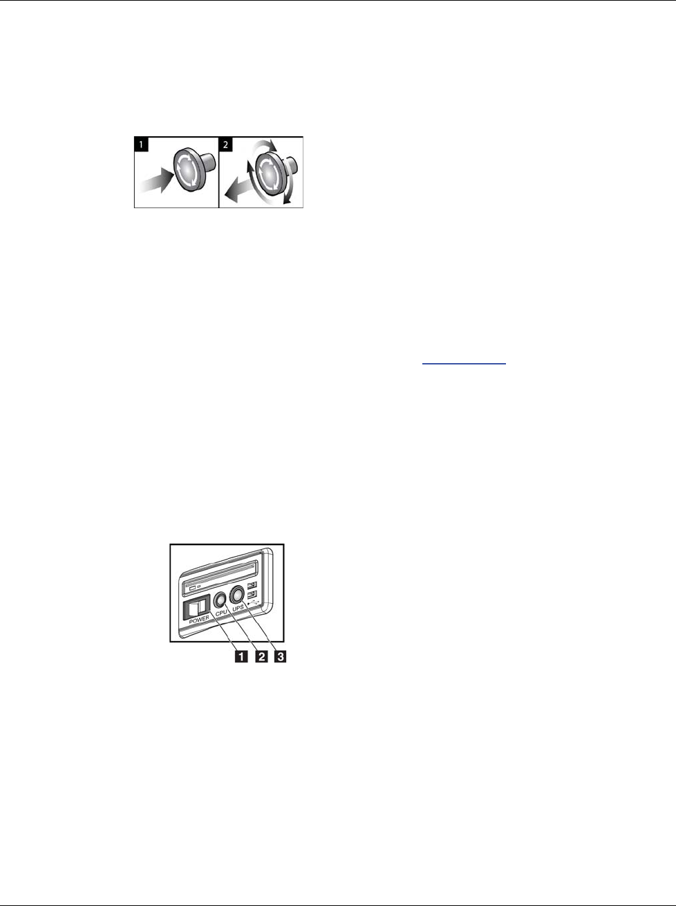
3Dimensions System User Guide
Chapter 4: Startup, Functional Tests, and Shutdown
Page 44 MAN-05085-002 Revision 002
DRAFT Preview Copy-Generated May 30, 2018
4.4 Emergency Off Switches Functionality
Figure 19: Emergency Off
Switch Functionality
There are three Emergency Off switches, one on each
side of the Gantry and one on the Acquisition
Workstation.
1. To turn Off the Gantry and disable the Acquisition
Workstation Lift Mechanism, press any of the
Emergency Off switches.
2. To reset the Emergency Off switch, turn clockwise
approximately one-quarter turn until the switch
pops back out.
4.5 How to Turn Off the System
1. Close any open patient procedures. Refer to Close a Patient on page 62.
2. From the Select Patient screen, select the Log Out button.
3. From the Startup screen, select the Shutdown button.
4. Select Yes in the confirmation dialog box.
4.6 How to Remove All Power from the System
See the following figure for illustrations of the buttons and switches referenced in the
following procedures.
Figure 20: Universal Acquisition
Workstation Power Buttons
Figure Legend
1. Acquisition Workstation Power Switch
2. Computer Power On/Reset Button
3. UPS Power Button
To remove all power from the system:
1. Turn off the system.
2. If your system includes the UPS, press the UPS button (item 3).
3. Turn OFF the acquisition workstation power switch (item 1).
4. Unplug the acquisition workstation power cable from the AC outlet.
5. Turn OFF the Gantry circuit breaker.
6. Turn OFF the Facility Mains circuit breaker.
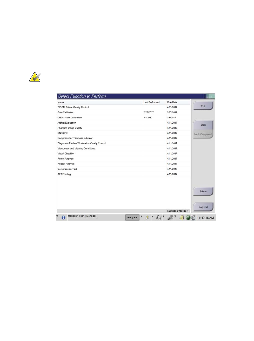
3Dimensions System User Guide
Chapter 5: User Interface
MAN-05085-002 Revision 002 Page 45
DRAFT Preview Copy-Generated May 30, 2018
5: User Interface
5.1 Select Function to Perform Screen
After login, the Select Function to Perform screen opens. This screen shows the quality
control tasks that are due.
Note
The Select Patient screen opens when no quality control tasks are scheduled to be done.
Figure 21: An Example Select Function to Perform Screen
To Complete a Scheduled Quality Control Task:
1. Select a Quality Control task from the list.
2. Select the Start button. Follow the messages to complete the procedure. (The Start
button is not available for all types of tests.)
- OR -
Select the Mark Completed button to mark the status of this procedure as finished.
Select Yes to confirm the selected procedure is completed.
3. Select End QC.
Chapter 5
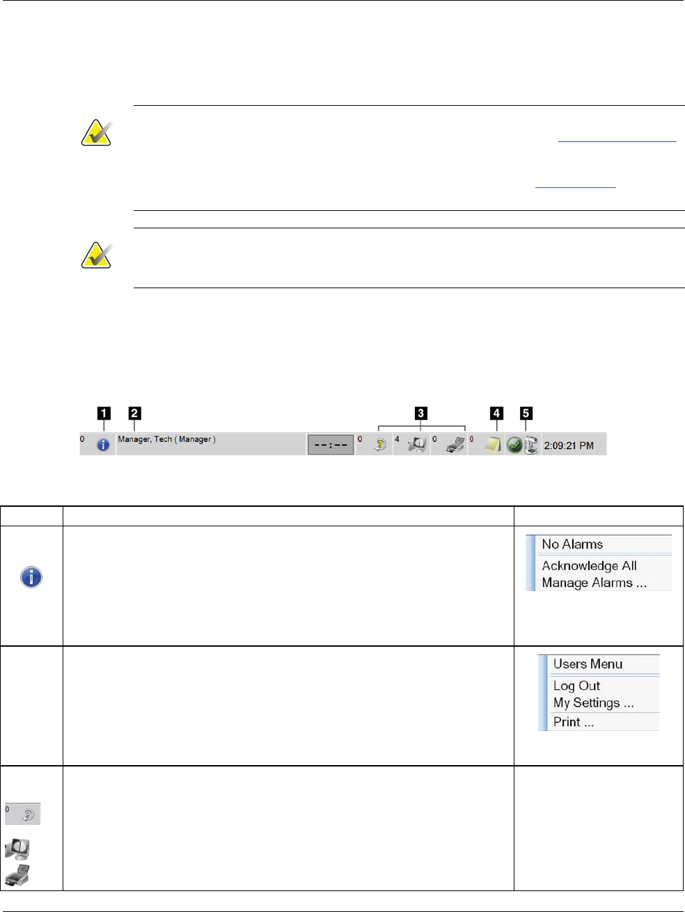
3Dimensions System User Guide
Chapter 5: User Interface
Page 46 MAN-05085-002 Revision 002
DRAFT Preview Copy-Generated May 30, 2018
To Proceed Without Completing All Scheduled Quality Control Tasks:
If all Quality Control tasks are not completed at this time, select the Skip button.
Note
If you select the Skip button, the Select Patient screen opens. Refer to Select Patient Screen
on page 48 for information about this screen.
If you select the Admin button, the Admin screen opens. Refer to Admin Screen on page
111 for information about this screen.
Note
Quality Control tasks are available to complete at any time. Select the Admin button
then the Quality Control button to access the list of Quality Control tasks.
5.2 About the Taskbar
The taskbar at the bottom of the screen displays additional icons. Select the icon to access
information or perform system tasks.
Figure 22: Taskbar
Table 12: Taskbar Menus
Description Menu
1
Information Icon
Select the Information icon to display a menu.
This section of the taskbar flashes a yellow color when an alarm exists.
Select Acknowledge All to stop the flashing indication.
Select Manage Alarms to display and close any open alarms.
2 Current User Name
Select the user name section of the taskbar to display the Users Menu.
Log Out returns you to the Startup screen.
My Settings lets you select user settings and workflow preferences.
Print sends the displayed patient list to a connected printer.
3
Output Device Icons
Select any output device icon to display the Manage Queues screen. This
screen displays the status of jobs in the queue, job information for the
selected output, and allows you to filter the queue display. The number
on the icon shows the number of jobs that remain in the queue.
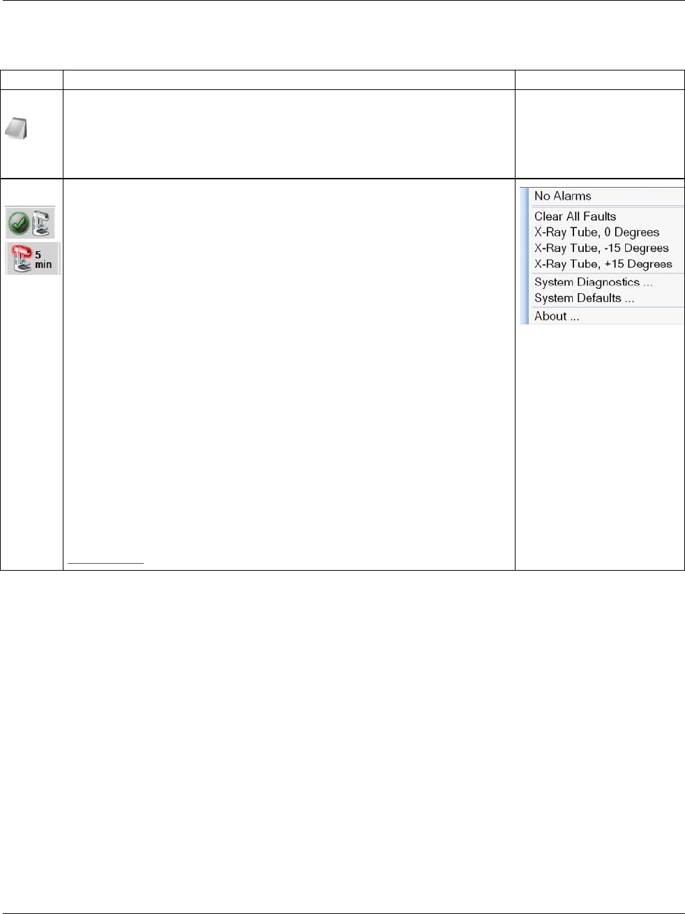
3Dimensions System User Guide
Chapter 5: User Interface
MAN-05085-002 Revision 002 Page 47
DRAFT Preview Copy-Generated May 30, 2018
Table 12: Taskbar Menus
Description Menu
4
Notices Icon
Select the Notice icon to display the Patients with Unviewed Notices
screen. The number on the icon shows the number of patients with
Unviewed Notices.
5
System Status Icons
Select the Tubehead icon to display a menu. When the detector and
generator are ready for use, a green checkmark appears next to the
tubehead icon. If the Tubehead icon is red with a number next to it, the
system needs to wait the number of minutes shown before the next
image can safely be taken.
Clear All Faults deletes all fault messages.
X-ray Tube, 0 Degrees puts the tubehead at zero degrees of rotation for
the next exposure.
X-ray Tube, -15 Degrees puts the tubehead at -15 degrees of rotation
for an exposure.
X-ray Tube, +15 Degrees puts the tubehead at +15 degrees of rotation
for an exposure.
System Diagnostics accesses Subsystem settings.
System Defaults opens the Gantry Defaults screen to set the
Compression and Generator default values.
About displays information about the Acquisition Workstation (refer to
About Screen on page 113).
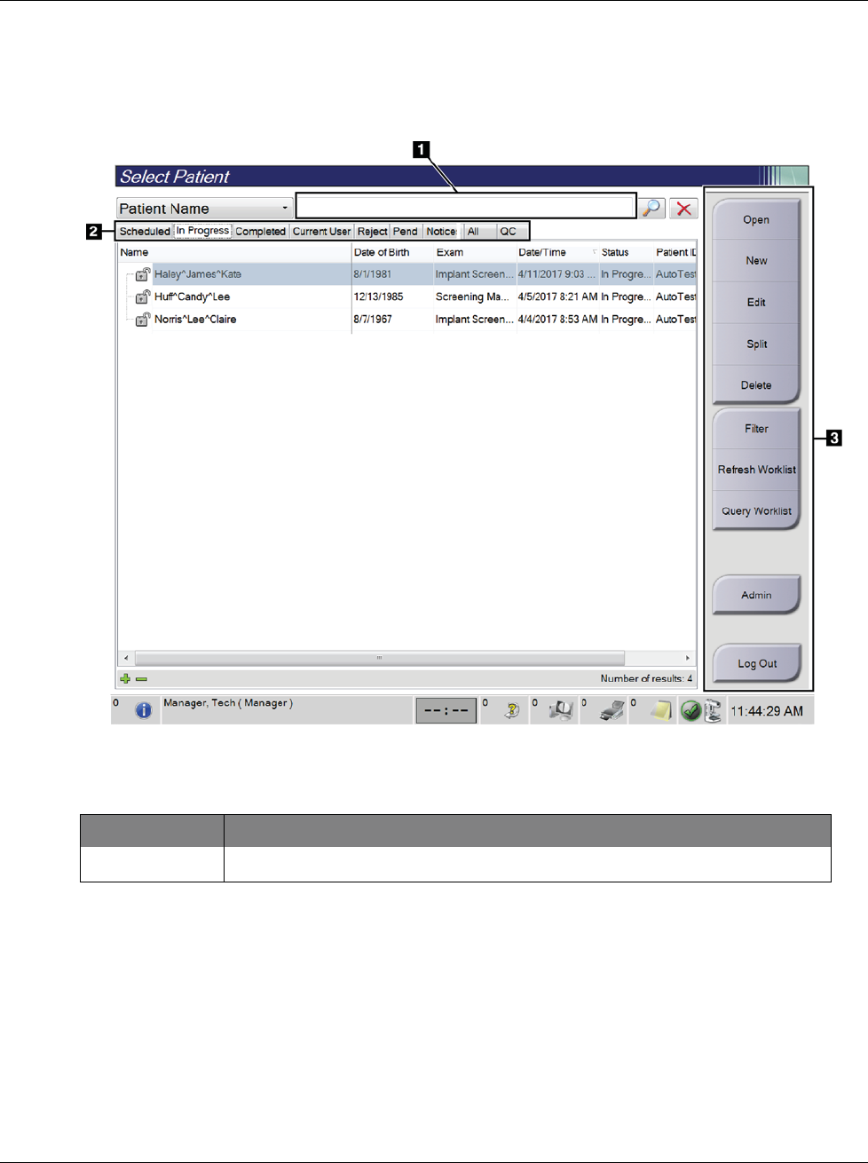
3Dimensions System User Guide
Chapter 5: User Interface
Page 48 MAN-05085-002 Revision 002
DRAFT Preview Copy-Generated May 30, 2018
5.3 Select Patient Screen
Figure 23: Select Patient Screen
Table 13: The Select Patient Screen
Item Description
1. Quick Search Search the selected tab for the Patient Name, Patient ID, or Accession #.
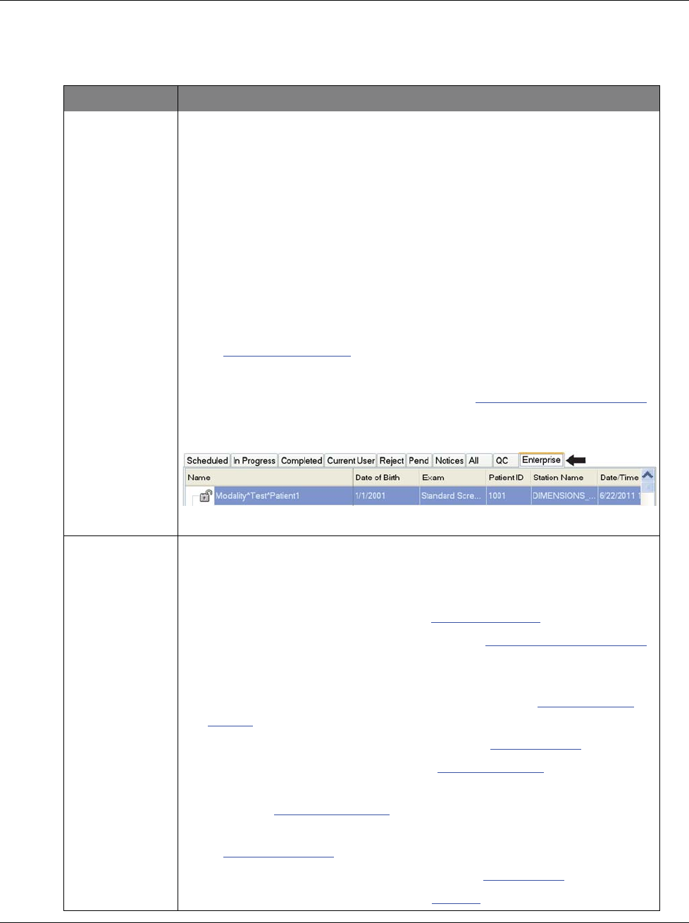
3Dimensions System User Guide
Chapter 5: User Interface
MAN-05085-002 Revision 002 Page 49
DRAFT Preview Copy-Generated May 30, 2018
Table 13: The Select Patient Screen
Item Description
2. Tabs The tabs at the top of the screen are configurable. A user with the correct
permissions can delete tabs and create new tabs.
xScheduled tab shows the scheduled procedures.
xIn Progress tab shows the procedures not complete.
xCompleted tab shows the completed procedures.
xCurrent User tab shows the procedures for the current operator.
xReject tab shows the procedures with rejected views.
xPend tab shows the procedures with pending views.
xAll tab shows all procedures for all users.
xNotices tab shows the patients with unviewed notices by default. Refer
to About the Notices Tab on page 50 for complete information.
xQC tab shows the Quality Control procedures.
xEnterprise tab is displayed if you have the Advanced Workflow Manager
on page 56. This tab shows the procedures acquired on all compatible
networked systems.
Figure 24: Enterprise Tab
3. Buttons Many functions are accessed from this screen by selecting a particular
button:
xOpen: Open the selected patient.
xNew: Add a new patient — refer to Add a New Patient on page 50.
xEdit: Edit the patient information — refer to Edit the Patient Information
on page 51.
xSplit: Remove the images from a procedure or a patient and move the
images to a different procedure or patient — refer to Split the Patient
Records on page 51.
xDelete: Delete the selected patient — refer to Delete a Patient on page 53.
xFilter: Use a Patient Filter — refer to Filters for Patients on page 53.
xRefresh Worklist: Update the Scheduled Patient Worklist information
— refer to Refresh the Worklist on page 55.
xQuery Worklist: Search for a patient in the Modality Worklist — refer
to Query the Worklist on page 55.
xAdmin: Access the Admin Screen — refer to Admin Screen on page 111.
xLog Out: Exit the system — refer to Log Out on page 55.
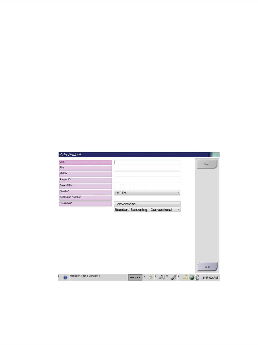
3Dimensions System User Guide
Chapter 5: User Interface
Page 50 MAN-05085-002 Revision 002
DRAFT Preview Copy-Generated May 30, 2018
5.3.1 About the Notices Tab
•After selecting the Notices tab from the Select Patient screen, a list of the Patients with
Notices is shown.
•The default value for the list is patients with Viewed and Unviewed Notices.
•You can change the value to show patients with Viewed Notices or patients with
Unviewed Notices.
•Select Open to access the Procedure screen for the selected patient.
5.3.2 Open a Patient
1. Select a tab to show the desired list of patients.
2. Select a patient from the list. The Open button becomes active.
3. Select Open to access the Procedure screen for that patient.
5.3.3 Add a New Patient
1. In the Select Patient screen, select the New button. The Add Patient screen opens.
Figure 25: Add Patient Screen
2. Enter the new patient information and select a procedure.
3. Select the Open button. The Procedure screen for the new patient opens.
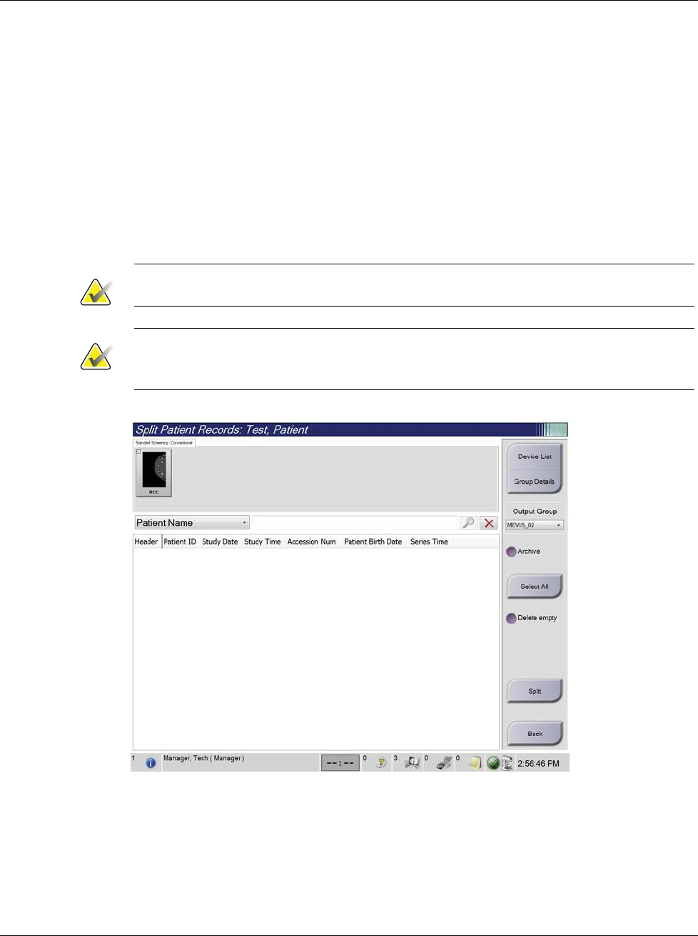
3Dimensions System User Guide
Chapter 5: User Interface
MAN-05085-002 Revision 002 Page 51
DRAFT Preview Copy-Generated May 30, 2018
5.3.4 Edit the Patient Information
1. In the Select Patient screen, select the patient name then select the Edit button.
2. In the Edit Patient screen, make changes then select the Save button.
3. Select OK to the Update Successful message.
5.3.5 Split the Patient Records
The Split function lets you move images when you acquired the images in the wrong
procedure or the wrong patient.
Note
You cannot split images for protected patients.
Note
Archived patient records still need correction on PACS or other archive systems after
using the Split function.
Figure 26: Split Patient Records Screen
Images Acquired in the Wrong Procedure
1. In the Select Patient screen, select the patient.
2. Select the Split button. The Split Patient Records screen opens.
3. Select the images to move. If all images are being moved, select Select All.
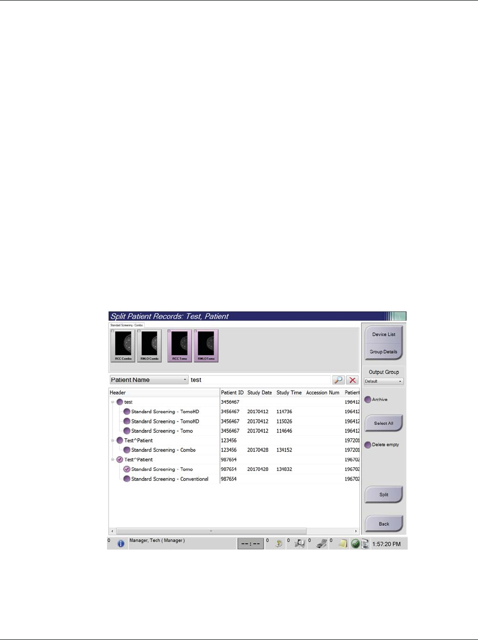
3Dimensions System User Guide
Chapter 5: User Interface
Page 52 MAN-05085-002 Revision 002
DRAFT Preview Copy-Generated May 30, 2018
4. Select your search criteria (for example, Patient Name or Accession Number) using
the drop-down menu below the images.
5. Enter the same patient information and select the Search button (the magnifying
glass).
6. When the Patient name appears, select the correct procedure for the images.
7. If you want to archive the images, select Archive.
8. Select Split, then select OK to the Split Successful message.
Images Acquired in the Wrong Patient
1. In the Select Patient screen, select the patient that has the images that need to be
moved.
2. Select the Split button. The Split Patient Records screen opens.
3. Select the images to move. If all images are being moved, select Select All.
4. Select your search criteria (for example, Patient Name or Accession Number) using
the drop-down menu below the images.
5. Enter the search criteria and select the Search button (the magnifying glass).
6. When the Patient name appears, select the correct procedure.
Figure 27: Select the Correct Procedure to Split Patient Records
7. If all images are being moved and you want to delete the incorrect patient from the
Patient List, check Delete Empty.
8. If you want to archive the images, select Archive.
9. Select Split, then select OK to the Split Successful message.
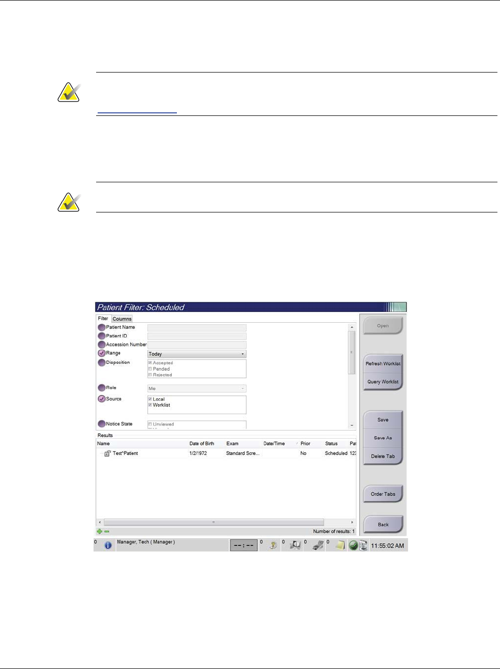
3Dimensions System User Guide
Chapter 5: User Interface
MAN-05085-002 Revision 002 Page 53
DRAFT Preview Copy-Generated May 30, 2018
5.3.6 Delete a Patient
Note
Reclamation normally removes the requirement to delete patients manually. Refer to
About Reclamation on page 110.
1. In the Select Patient screen, select one or more patients.
2. Select the Delete button.
3. When the confirmation prompt is shown, select Yes.
Note
The Technologists do not have permissions to delete patients.
5.3.7 Filters for Patients
After selecting the Filter button in the Select Patient screen, the Patient Filter screen for the
selected patient list opens.
Figure 28: Filter Tab in the Patient Filter Screen

3Dimensions System User Guide
Chapter 5: User Interface
Page 54 MAN-05085-002 Revision 002
DRAFT Preview Copy-Generated May 30, 2018
Filter Tab
Use the Filter tab to change the filter options for the patient list. When you select or
cancel an option, the change shows in the Results area of the screen.
Note
You must have Manager level access to save these new filters to the selected tab in the
Select Patient screen. (Refer to Other Functions of the Filter Tab on page 54.)
Note
When you select a line in the results list then select the Open button, the Procedure
screen for the selected patient opens.
Other Functions of the Filter Tab
The Filter tab allows users with access privileges to add, change, or delete tabs in the
Select Patient screen. Refer to the following table.
Table 14: Filter Tab Options (Require Access Privileges)
Change the current patient
filter parameters.
1. Select a tab on the Select Patient screen.
2. Select the Filter button.
3. Select the filter options.
4. Select the Save button.
5. Make sure the name of the tab you selected is in
the name box.
6. Select OK.
Create a new tab for the Select
Patient screen.
1. Select a tab on the Select Patient screen.
2. Select the Filter button.
3. Select the filter options for the tab.
4. Select the Save As button.
5. Enter a new name for the tab.
6. Select OK.
Delete a tab from the Select
Patient screen.
1. Select a tab on the Select Patient screen.
2. Select the Filter button.
3. Select the Delete button.
4. Select Yes in the confirmation dialog box.

3Dimensions System User Guide
Chapter 5: User Interface
MAN-05085-002 Revision 002 Page 55
DRAFT Preview Copy-Generated May 30, 2018
Columns Tab
Use the Columns tab to add more search options (for example, Age, Gender, Notices) to
the filtered list. The options show as columns in the results area. To add more columns to
a filtered list, select the Columns tab then select the options.
Note
You must have Manager level access to save these new columns to the patient filter.
Note
When you select a line in the results list then select the Open button, the Procedure
screen for the selected patient opens.
Order Tabs Button
Select the Order Tabs button to change the order of the patient list tabs.
5.3.8 Refresh the Worklist
Select the Refresh Worklist button to update the Scheduled patient list from the
Modality Worklist Provider.
5.3.9 Query the Worklist
Select the Query Worklist button to search the Modality Worklist Provider for a patient
or a list of patients.
There are two methods to enter the query information:
•Keyboard—Type the query information into one or more fields. The scheduled
procedure is displayed, and the patient is added to the local database. All fields to
query are configurable. The default fields are Patient name, Patient ID, Accession
Number, Requested Procedure ID, and Scheduled Procedure Date.
•Bar Code Scanner—Scan the bar code for the configured query field. The scheduled
procedure is displayed, and the patient is added to the local database. The field in
which the bar code scanner scans is configurable. The default query field can be the
Patient ID, Accession Number, or Requested Procedure ID.
5.3.10 Admin
Select the Admin button to access the Admin screen and the system administration
functions. Refer to System Administration Interface on page 111 for more information.
5.3.11 Log Out
Select the Log Out button to exit the system and return to the Startup screen.
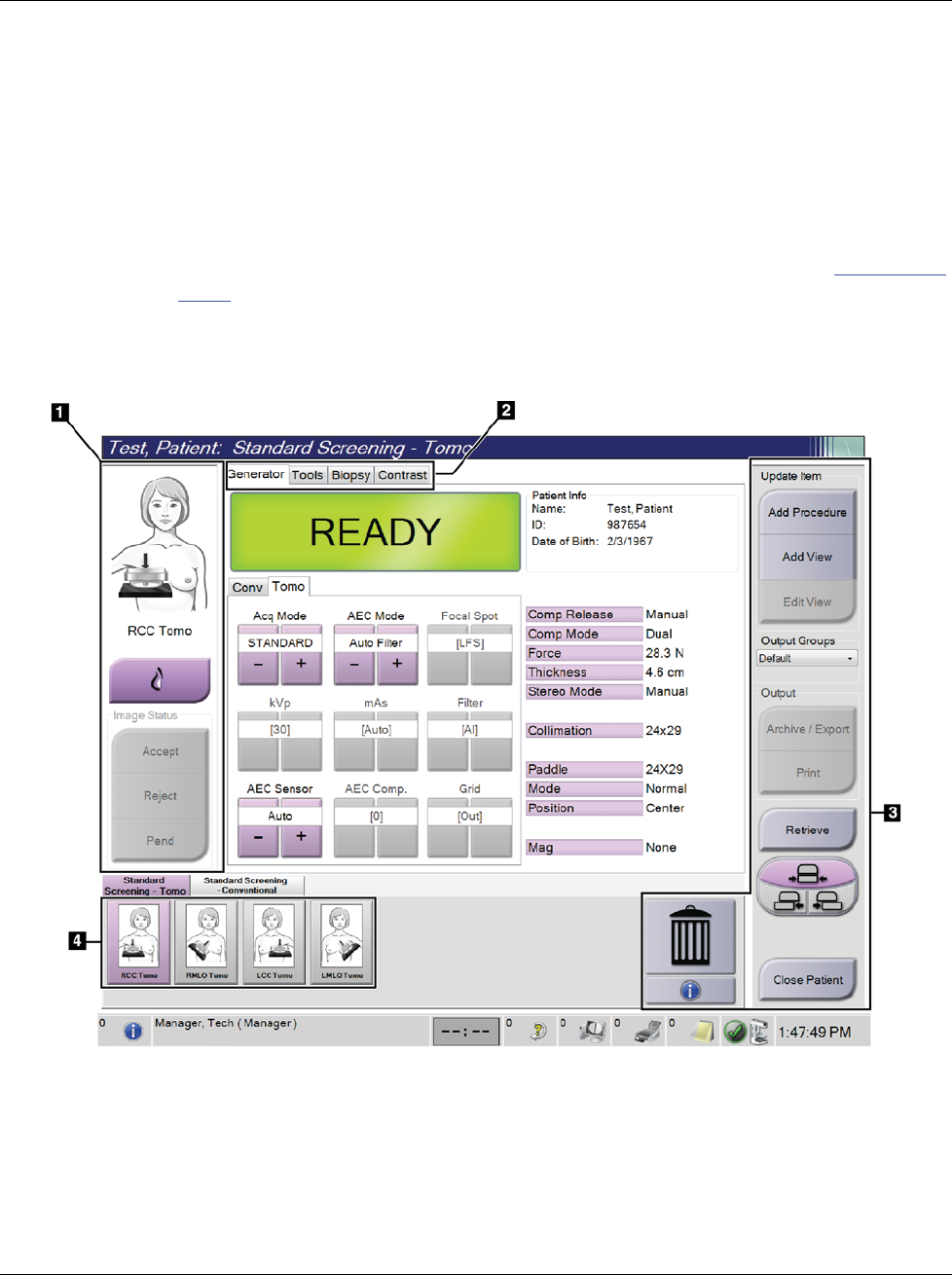
3Dimensions System User Guide
Chapter 5: User Interface
Page 56 MAN-05085-002 Revision 002
DRAFT Preview Copy-Generated May 30, 2018
5.3.12 Advanced Workflow Manager
The Advanced Workflow Manager is a workflow engine that allows compatible Hologic
systems to communicate and exchange images with each other. The Advanced Workflow
Manager keeps track of all patients, procedures, and images acquired on all systems
within an Advanced Workflow Manager cluster. In addition, the Advanced Workflow
Manager synchronizes notices and provides images to all systems within the cluster.
Systems with Advanced Workflow Manager show the Enterprise tab on the Select Patient
Screen on page 48. This tab lists the procedures acquired on all systems within an
Advanced Workflow Manager cluster.
5.4 Procedure Screen
Figure 29: Procedure Screen
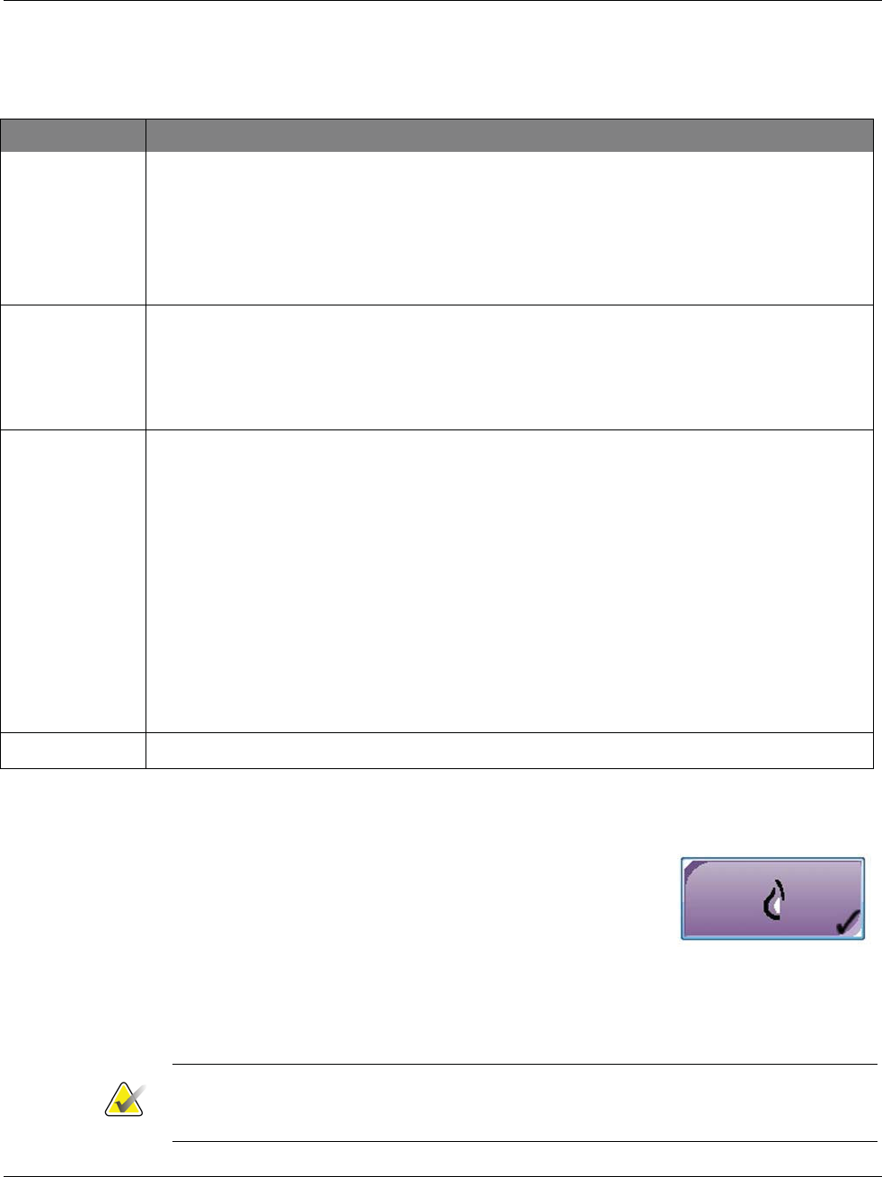
3Dimensions System User Guide
Chapter 5: User Interface
MAN-05085-002 Revision 002 Page 57
DRAFT Preview Copy-Generated May 30, 2018
Table 15: The Procedure Screen
Item Description
1. Image Status The view icon shows the current selected view.
Implant Present button—select when the patient has an implant.
Accept button—select to accept the image.
Reject button—select to reject the image.
Pend button—select to save the image for future review.
2. Tabs Select the Generator tab to adjust the exposure techniques for the procedure.
Select the Tools tab to review the images.
Select the Biopsy tab to create targets.
Select the Contrast tab to perform I-View™ 2D Contrast procedures.
3. Buttons Many functions are accessed from this screen by selecting a particular button:
Add Procedure: Add a new patient.
Add View: Add a new view.
Edit View: Assign a different view to an image.
Archive/Export: Send images to an output.
Print: Print images.
Retrieve: Query the configured devices with the current patient information.
Paddle Shift: Bypass the default paddle position for the selected view.
Close Patient: Exit the patient and procedure.
Trash Can: Delete a view.
4. Thumbnails Select a tab to show the thumbnail views or the thumbnail images for that procedure.
5.4.1 How to Use the Implant Present Button
The Implant Present button is above the Accept button on the
Procedure screen. This button applies special implant
processing to the implant and implant displaced views, and
changes the "Implant Present" DICOM tag in the image
header. When this button is selected, a check mark appears on
the button.
Select the Implant Present button for both implant and implant displaced views before
you acquire the image.
Note
The Implant Present button is automatically selected if any procedure tabs contain an
ID view.
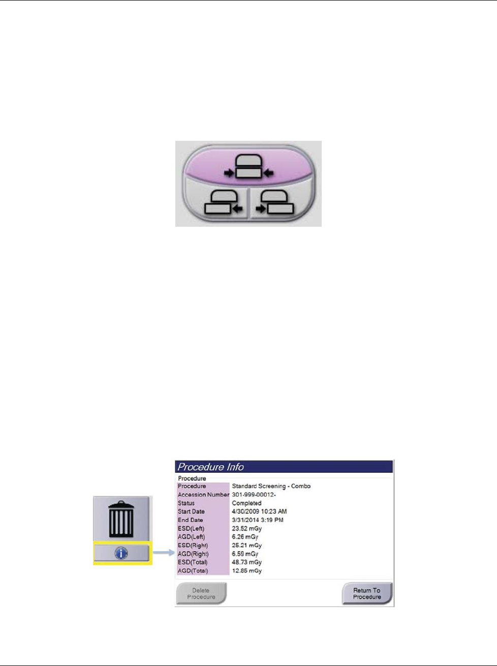
3Dimensions System User Guide
Chapter 5: User Interface
Page 58 MAN-05085-002 Revision 002
DRAFT Preview Copy-Generated May 30, 2018
5.4.2 How to Use the Paddle Shift Feature
Refer to Paddle Shift for information about the Paddle Shift feature.
1. In the Procedure screen, select an unexposed thumbnail image view. The paddle
moves to the default position for that view.
2. Select a paddle shift button to bypass the default paddle position for the selected
view. The paddle moves to the new position.
Figure 30: Paddle Shift Buttons
5.4.3 Procedure Information Dialog Box
To show procedure information, select the Procedure Information button located below
the Delete View (trash can) button. The Procedure Info dialog box opens with the
following information:
•Procedure Name
•Accession Number
•Procedure Status
•Procedure Start and End Date and Time
•Dose Information (each Breast and Cumulative)
For procedures that contain no exposed views, select the Delete Procedure button to
remove the selected procedure from the patient. Select Return to Procedure to exit the
dialog box.
Figure 31: Procedure Info Dialog Box
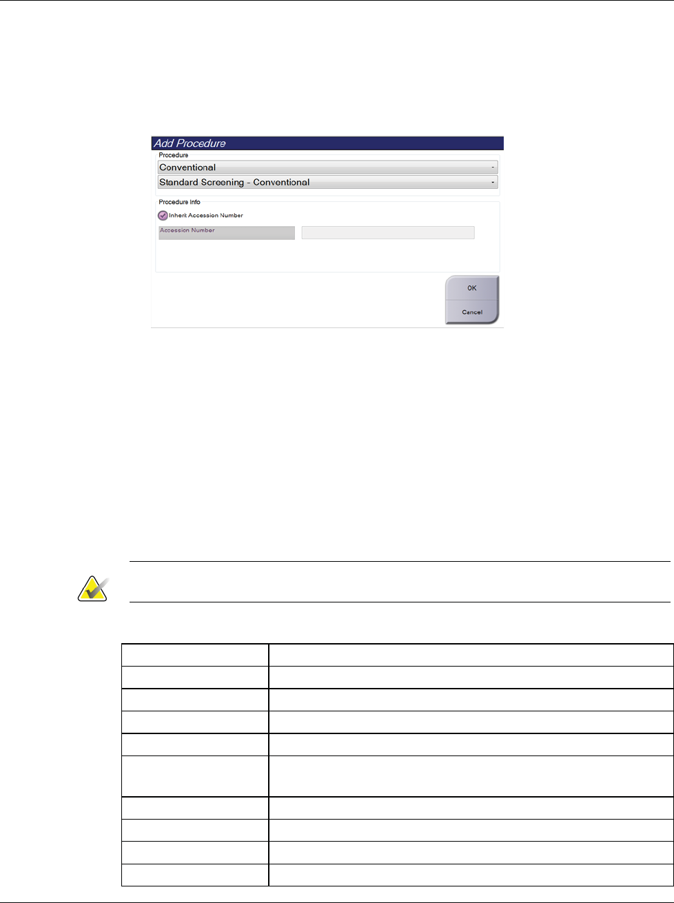
3Dimensions System User Guide
Chapter 5: User Interface
MAN-05085-002 Revision 002 Page 59
DRAFT Preview Copy-Generated May 30, 2018
5.4.4 Add a Procedure
1. To add another procedure, select the Add Procedure button on the Procedure screen
to access the Add Procedure dialog box.
Figure 32: Add Procedure Dialog Box
2. Use the drop-down menus to select the type of procedure to add.
3. The current Accession Number is automatically used. To use a different Accession
Number, deselect the "Inherit Accession Number" check box and enter the desired
number.
4. Select the OK button. A new tab is added with the thumbnail views for the
procedure that was selected.
Available Procedures
The table that follows shows the major groups of procedures that are available on the
system.
Note
Some procedures in the list show only when the system is licensed for that procedure.
Table 16: Procedure Groups
Procedure Description
Conventional Digital mammography (2D) imaging only
Combo Digital mammography (2D) and breast tomosynthesis imaging
Tomo Breast tomosynthesis imaging only
TomoHD Breast tomosynthesis imaging and a generated 2D image
ComboHD Digital mammography (2D) and breast tomosynthesis imaging
and a generated 2D image
Stereo Biopsy Biopsy that uses stereotactic targeting
Tomo Guided Biopsy Biopsy that uses tomosynthesis targeting
Specimen Specialized specimen imaging
2D Contrast Contrast enhanced digital imaging
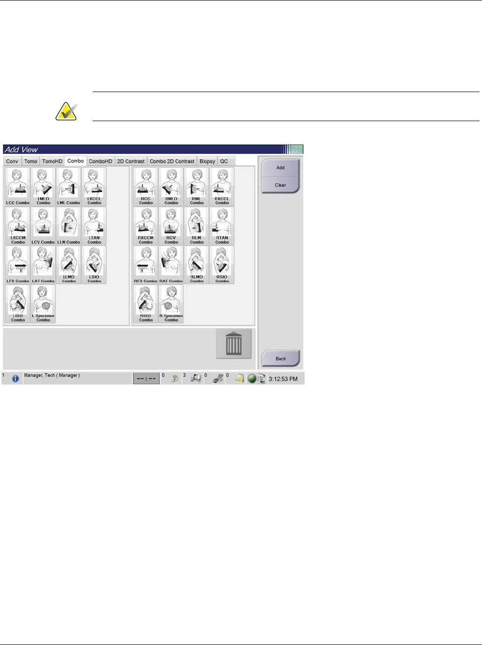
3Dimensions System User Guide
Chapter 5: User Interface
Page 60 MAN-05085-002 Revision 002
DRAFT Preview Copy-Generated May 30, 2018
5.4.5 Add (or Remove) a View
To Add a View
1. Select the Add View button to access the Add View screen.
Note
Depending on the license settings for your system, you may see different tabs.
Figure 33: Add View Screen
View Modifiers
ID = Implant Displaced
RL = Rolled Lateral
RM = Rolled Medial
RI = Rolled Inferior
RS = Rolled Superior
NP = Nipple in Profile
AC = Anterior Compression
IMF = Infra-Mammary Fold
AX = Axillary Tissue
2. Select the tab, then select the view. You can select a maximum of three View
Modifiers from the right panel of the screen.
3. Select the Add button. A thumbnail image of each selected view is added in the
bottom panel of the screen.
To Remove a View
•To remove a single view from the added list: select the view then select the trash can
icon.
•To remove all views from the added list: select the Clear button.
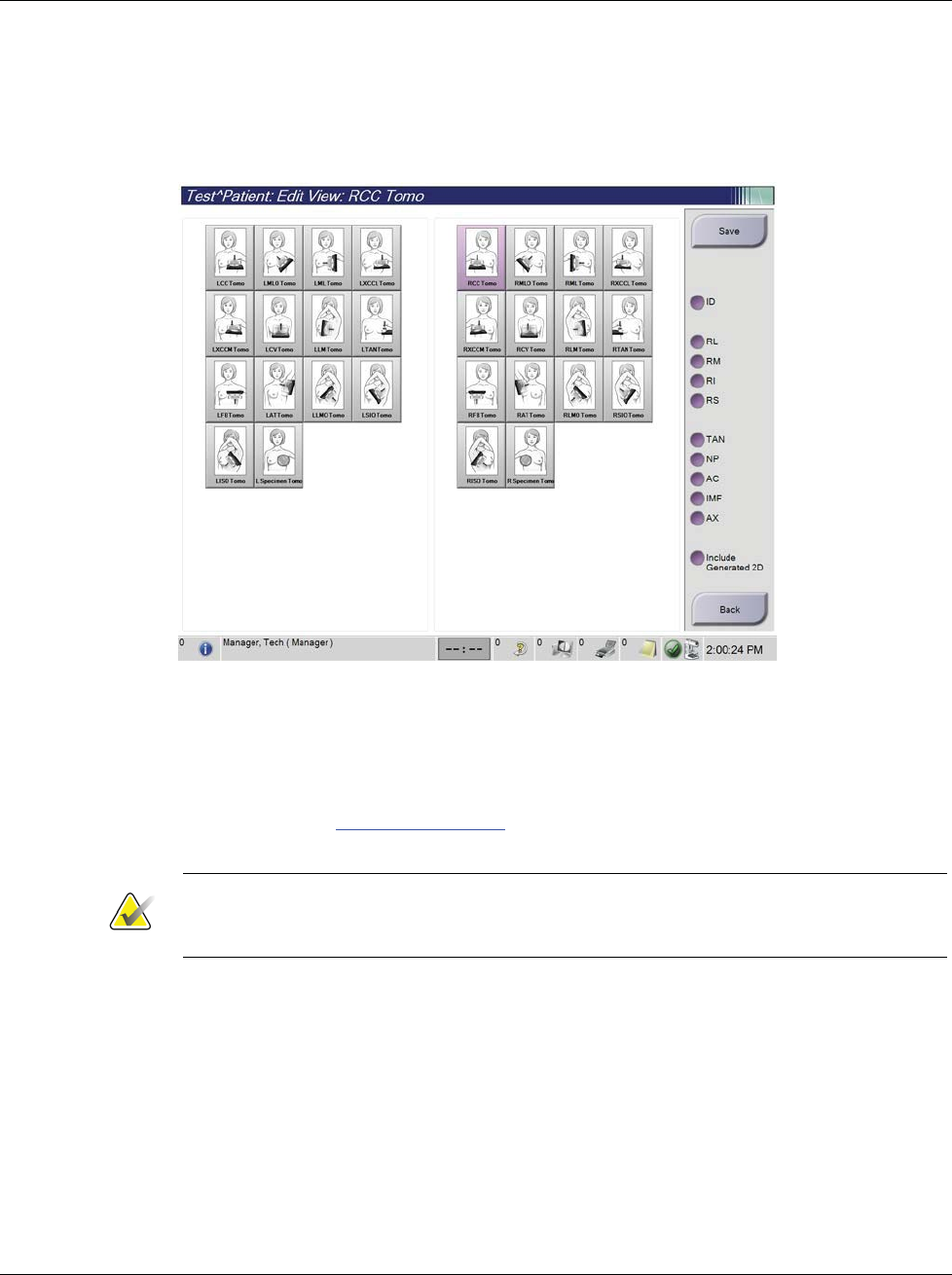
3Dimensions System User Guide
Chapter 5: User Interface
MAN-05085-002 Revision 002 Page 61
DRAFT Preview Copy-Generated May 30, 2018
5.4.6 Edit a View
Use the Edit View screen to assign a different view to an image.
Figure 34: Edit View Screen
1. In the Procedure screen, select an exposed thumbnail image view.
2. Select the Edit View button.
3. Select the view from the screen. You can select a maximum of three View Modifiers.
See the figure The Add View Screen on page 60 for a description of the View Modifiers.
4. Select Save, then select OK to the Update Successful message.
Note
The Edit View screen for biopsy procedures shows different View Modifiers. Refer to the
Affirm System User Guide.
5.4.7 Retrieve
Select the Retrieve button to query the configured devices with the current patient
information. The Retrieve button performs the same function as the Query Retrieve
button in the Admin screen.
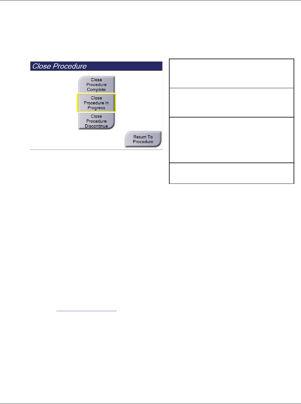
3Dimensions System User Guide
Chapter 5: User Interface
Page 62 MAN-05085-002 Revision 002
DRAFT Preview Copy-Generated May 30, 2018
5.4.8 Close a Patient
Select the Close Patient button. If images were acquired, a Close Procedure dialog box
opens. Select one of the following options:
Close Procedure Complete: Closes the
procedure and puts the procedure in the
Completed tab.
Close Procedure In Progress: Closes the
procedure and puts the procedure in the In
Progress tab.
Close Procedure Discontinue: Closes the
procedure and puts the procedure in the All
tab. A dialog box opens and you must select
the reason the procedure was discontinued
from a list or add a new reason.
Return To Procedure: Returns to the
procedure.
If there are images marked as Pend, a dialog box opens with the following options:
•Accept All and Close Complete
•Close Procedure In Progress
•Return to Procedure
If MPPS is activated, procedure status information is sent to the output devices when you
select Complete or Discontinue. You can also click and hold the tab above the thumbnail
images to resend a message about the procedure status during the procedure. A
Procedure Action dialog box opens with buttons to resend a status or to return to the
procedure.
5.5 How to Access the Image Review Features
Select the Tools tab on the Procedure screen to access the image review features. Refer to
Image Review Tools Tab on page 75 for information.
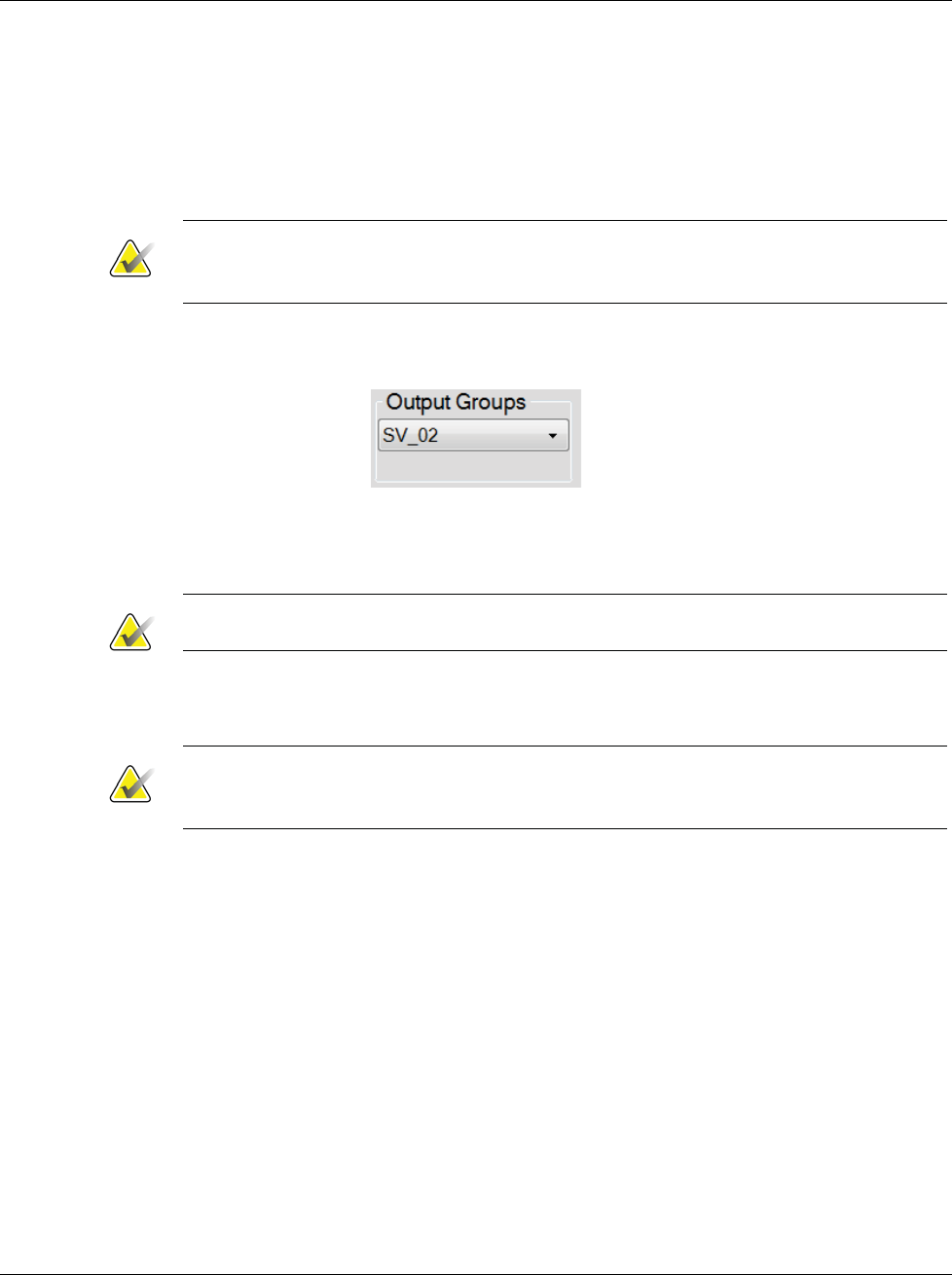
3Dimensions System User Guide
Chapter 5: User Interface
MAN-05085-002 Revision 002 Page 63
DRAFT Preview Copy-Generated May 30, 2018
5.6 Output Groups
The accepted images are sent automatically to the output devices in the selected Output
Group. The system configuration controls if the images are sent after a patient is closed
or after the image is accepted.
Note
Tomosynthesis images are not sent to a print device in the selected Output Group. You
can print selected tomosynthesis images from the Print screen.
5.6.1 Select an Output Group
Figure 35: Output Groups Field
Select an output device group like PACS, Diagnostic Workstations, CAD devices and
printers from the Output Groups drop-down list in the Procedure screen.
Note
Images are not sent if an Output Group is not selected.
5.6.2 Add or Edit an Output Group
Note
The configuration of Output Groups occurs during installation, but you can edit
existing groups or add new groups.
To add a new Output Group:
1. Access the Admin screen.
2. Select the Manage Output Groups button.
3. Select the New button, enter the information, then select the output device(s).
4. Select Add, then select OK in the Update Successful message.
5. You can select any group to set as the default.
To edit an Output Group:
1. Access the Admin screen.
2. Select the Manage Output Groups button.
3. Select the Edit button, then make the changes.
4. Select Save, then select OK in the Update Successful message.
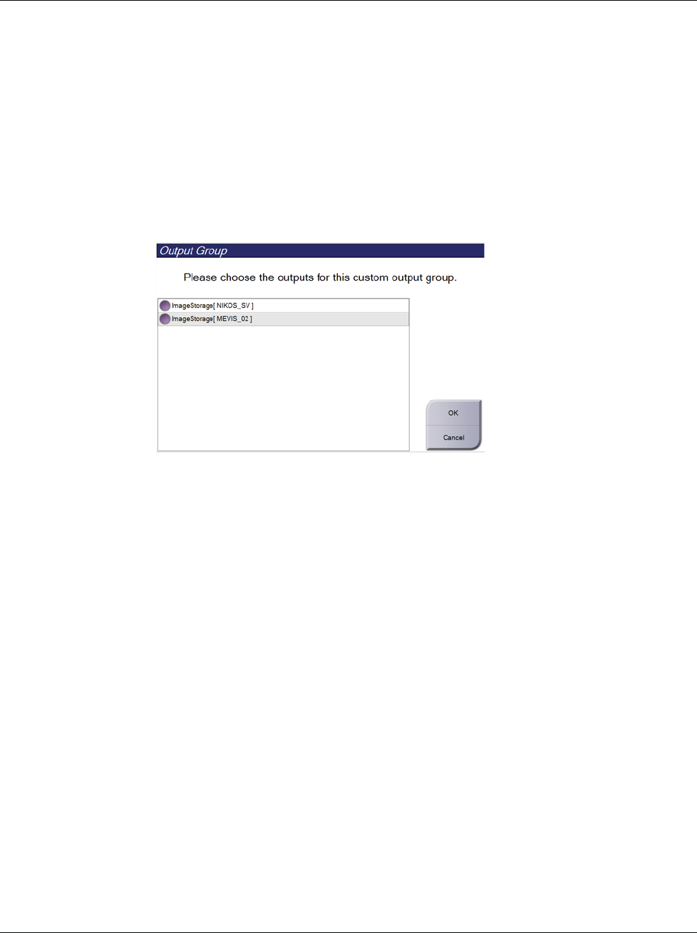
3Dimensions System User Guide
Chapter 5: User Interface
Page 64 MAN-05085-002 Revision 002
DRAFT Preview Copy-Generated May 30, 2018
5.6.3 Custom Output
The Custom Output option lets you make an output group from the Procedure screen. The
custom group that you make stays as the Custom option until another custom group is
made.
To Make a Custom Group from the Procedure screen:
1. In the Procedure screen, select Custom from the Output Groups drop-down menu.
2. In the Output Group screen, select from the list of available devices, then select OK.
Figure 36: An Example Custom Output Group
5.7 On-Demand Outputs
The On-Demand Outputs are Archive/Export or Print. You can manually Archive,
Export, or Print the currently opened patient until the procedure is closed.
When you select an On-Demand Output button, you have the option to send images
from the patient that is open to any of the configured output devices.
5.7.1 Archive
1. Select the Archive/Export button.
2. Select the procedure or views in the On Demand Archive screen:
•Select All button selects all items that show in this screen.
•Clear button deselects items that are selected in this screen.
•Priors button shows previous procedures and views for this patient.
•Rejected button shows rejected views for this patient.
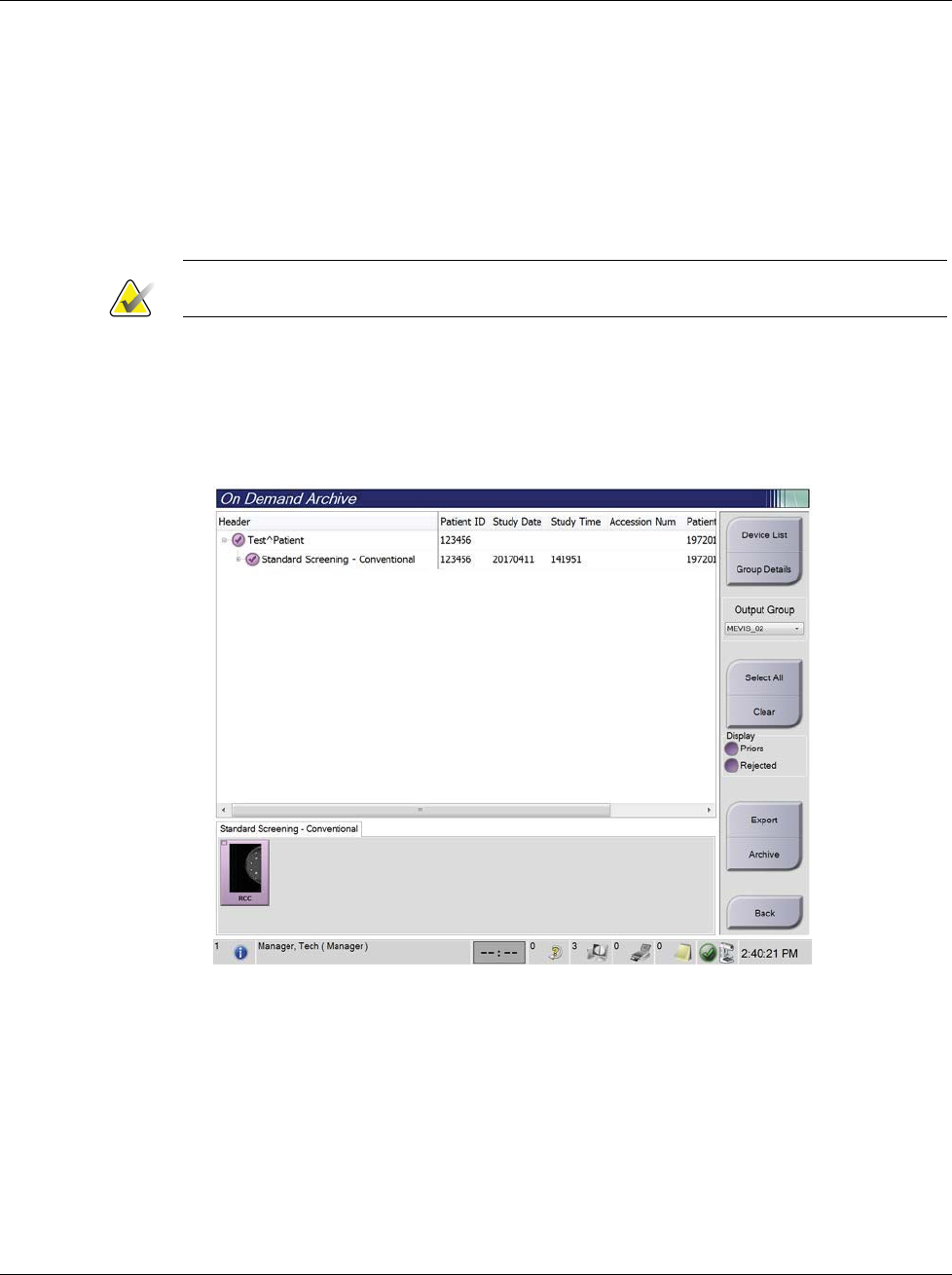
3Dimensions System User Guide
Chapter 5: User Interface
MAN-05085-002 Revision 002 Page 65
DRAFT Preview Copy-Generated May 30, 2018
3. Select a storage device:
•Select the Device List button and make your selection from the options in the
Storage Device drop-down menu.
-OR-
•Select an output group from the Output Group drop-down list.
4. Select the Archive button to send the selected images to the selected archive.
Note
Use the Manage Queue utility in the taskbar to review the archive status.
5.7.2 Export
1. Select the Archive/Export button (on the right side of the Procedure screen).
2. Select the images to export, then select the Export button.
Figure 37: Select the Images for Export
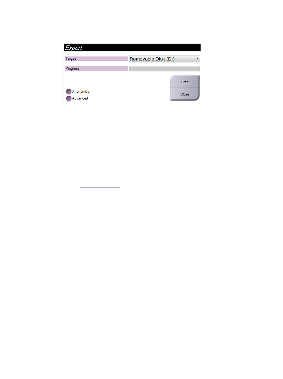
3Dimensions System User Guide
Chapter 5: User Interface
Page 66 MAN-05085-002 Revision 002
DRAFT Preview Copy-Generated May 30, 2018
3. In the Export dialog box, select the target from the drop-down menu of media
devices.
Figure 38: Export Dialog Box
•To anonymize patient data, select Anonymize
•To select a folder on your local systems for storage of your selections and to
select the Export types, select Advanced.
4. Select the Start button to copy the selected images to the selected device.
5.7.3 Print
1. From the Procedure screen, select the Print button to show the Print screen. See the
figure The Print Screen on page 67 to prepare your print data.
2. Select the film format from the film format area of the screen.
3. Select a thumbnail image.
4. Select the image mode (Conventional, Projection, or Reconstruction). The C-View
button shows if the system is licensed for C-View imaging.
5. Select the print preview area (item 16) in the Print screen. The image that shows in
this area is the image that prints on the film.
6. To put other images on the same multiformat film, repeat steps 3 through 5.
7. To print a different film format of the same images, select the New Film button (item
12), then complete steps 2 through 6.
8. Use the buttons in the top left area of the Print screen (item 1 through item 6) to hide
or show patient data, markings and annotations, and to change the orientation of the
image.
9. Select the Print button to print your films.
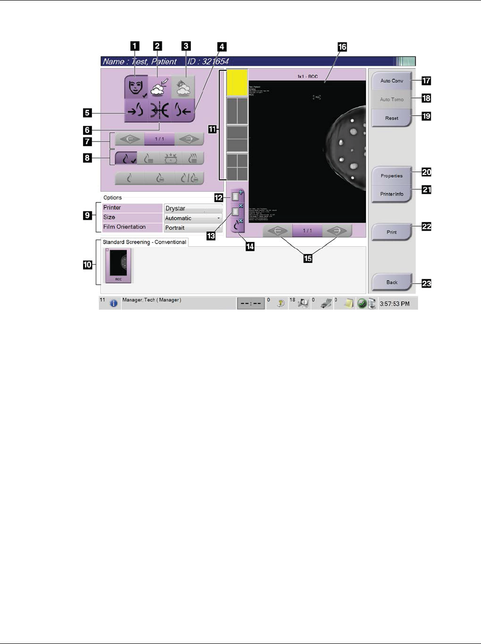
3Dimensions System User Guide
Chapter 5: User Interface
MAN-05085-002 Revision 002 Page 67
DRAFT Preview Copy-Generated May 30, 2018
Figure 39: Print Screen
Figure Legend
1. Show or hide patient data.
2. Show or hide markings and annotations.
3. Show or hide targets in images from a biopsy.
4. Print the image from a dorsal perspective.
5. Print the image from a ventral perspective.
6. Reverse (mirror) the image.
7. Go to previous or next tomosynthesis slice or
projection (Tomosynthesis option).
8. Select Conventional, Projection, or
Reconstruction views (Tomosynthesis option).
The C-View button shows if the system is
licensed for C-View imaging.
9. Select the printer options.
10. View Thumbnail images.
11. Select the film format (number of tiles).
12. Create a new film.
13. Delete a film.
14. Delete an image from a film.
15. Step through the film pages.
16. Print preview area.
17. Print Conventional (and C-View images, if
system is licensed) with the default setup.
18. Print tomosynthesis images (slices or projections)
Tagged for Print (Tomosynthesis option).
19. Return the Print screen to default settings.
20. Open the Properties screen.
21. Show the printer IP address, AE Title, Port and
capability for True Size print.
22. Start the print process.
23. Return to the Procedure screen.
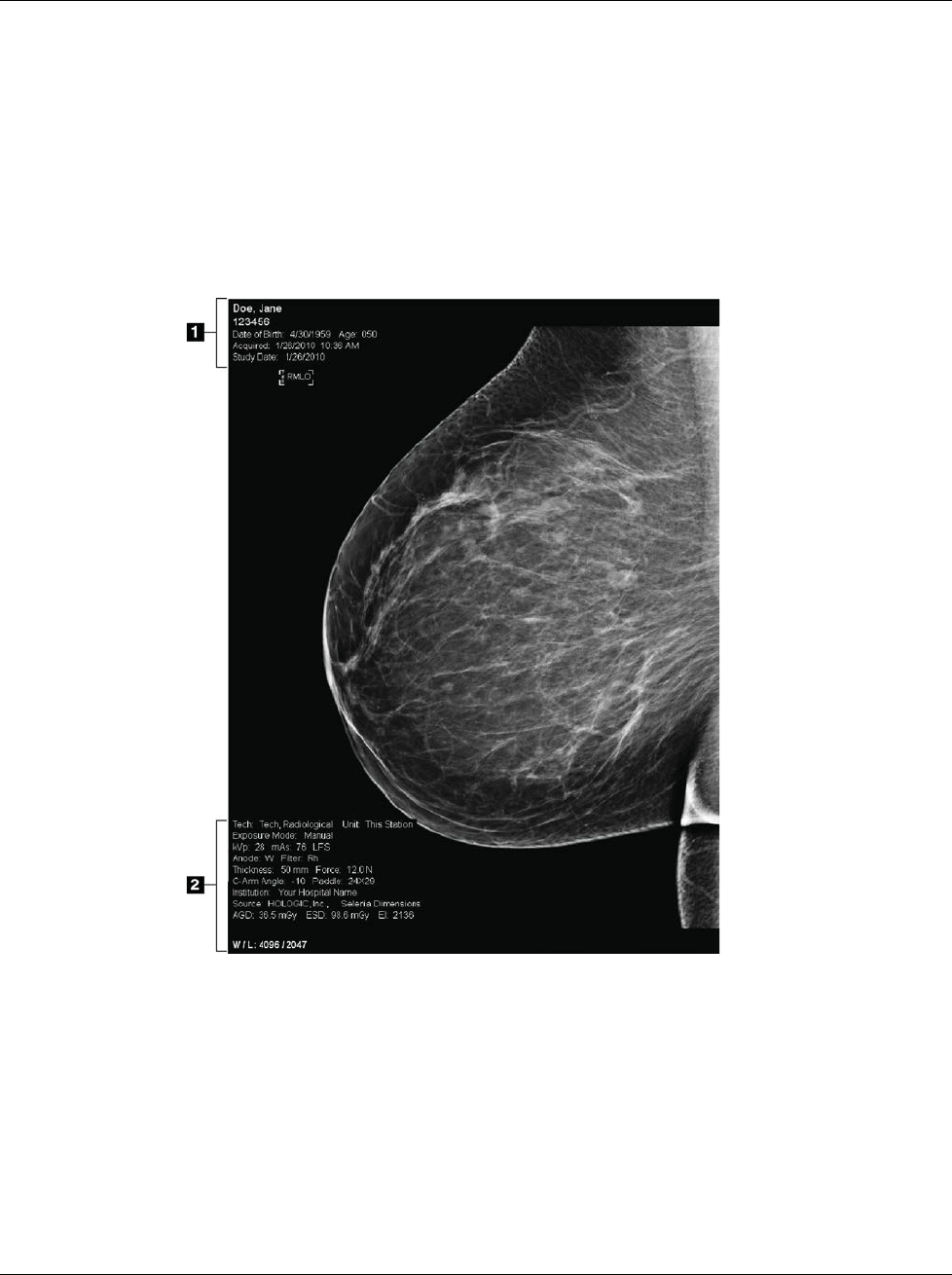
3Dimensions System User Guide
Chapter 6: Images
MAN-05085-002 Revision 002 Page 69
DRAFT Preview Copy-Generated May 30, 2018
6: Images
6.1 Image Display Screen
After you make an exposure, the acquired image opens on the Image Display monitor.
Patient and procedure information can be displayed on the screen. To turn the
information on or off, go to the Tools tab in the Procedure screen and select the Patient
Information button.
Figure 40: Image Display Screen
Figure Legend
1. Patient information and exam date
2. Exposure information, including:
xExposure techniques
xPatient dose
xC-arm angle
xCompression thickness and force
xFacility and technologist information
Chapter 6

3Dimensions System User Guide
Chapter 6: Images
Page 70 MAN-05085-002 Revision 002
DRAFT Preview Copy-Generated May 30, 2018
6.2 How to Set the Exposure Parameters
6.2.1 Select the Image Acquisition Mode (Tomosynthesis Option)
xStandard For routine Tomosynthesis screening procedures
xEnhanced For diagnostic Tomosynthesis views
Warning:
Enhanced acquisition mode with combo mode imaging (DM + BT) can
produce radiation dose that is higher than the MQSA screening limit of 3.0
mGy and therefore should only be used in diagnostic evaluation.
6.2.2 Select the Exposure Mode
Use the Automatic Exposure Control modes (AEC) to let the system control the exposure
techniques. AEC modes are available from 20-49 kV.
xManual The user selects the kV, mAs, Focal Spot, and Filter.
xAEC: Auto-Time The user selects the kV, Focal Spot, and Filter. The system
selects the mAs.
xAEC: Auto-kV The user selects the Focal Spot. The system selects the kV,
mAs, and Filter (Rhodium).
xAEC: Auto-Filter The user selects the Focal Spot. The system selects the kV,
mAs, and Filter.
6.2.3 How to Use the AEC Sensor
The AEC Sensor has seven manual positions and an automatic position. The manual
positions start at the chest wall edge (position 1) and reach toward the nipple edge
(position 7). The automatic position selects two regions within an area that extends from
the chest wall to the nipple.
Use the plus (+) and minus (-) keys on the Compression Device or in the AEC Sensor area
of the screen to change the sensor position. You can select Auto AEC to allow the system
to calculate the best exposure for the breast.
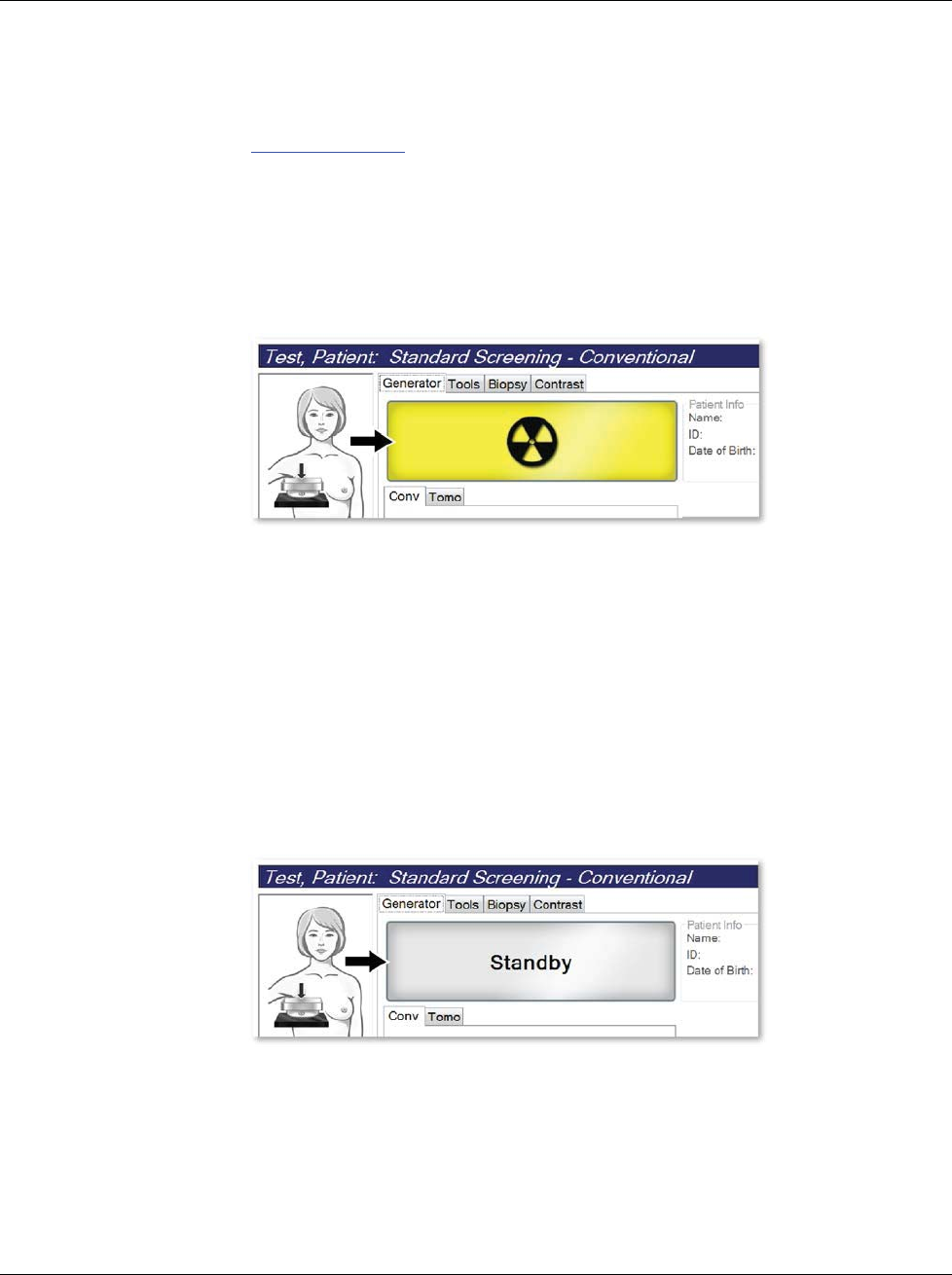
3Dimensions System User Guide
Chapter 6: Images
MAN-05085-002 Revision 002 Page 71
DRAFT Preview Copy-Generated May 30, 2018
6.3 How to Acquire an Image
Refer to Clinical Procedures on page 99 for information about clinical procedures.
1. Select a view from the thumbnail views at the bottom of the Procedure screen.
2. Press and hold the x-ray button and/or the x-ray footswitch for the full exposure.
During the exposure:
•The System Status bar shows the radiation symbol and a yellow background (see
the following figure).
Figure 41: Exposure In Progress
•An audible tone continues to sound during the exposure
The audible tone is a continuous sequence of tones. The tone sounds during the
entire combo acquisition from the initiation of the exposure to the end of the
conventional view. There is no interruption of the audible tone between breast
tomosynthesis and conventional digital mammography exposures. Do not
release the exposure switch during the audible tone.
3. When the tone stops and the System Status bar shows Standby (see the following
figure), release the x-ray button and/or the x-ray footswitch.
Figure 42: Exposure Complete
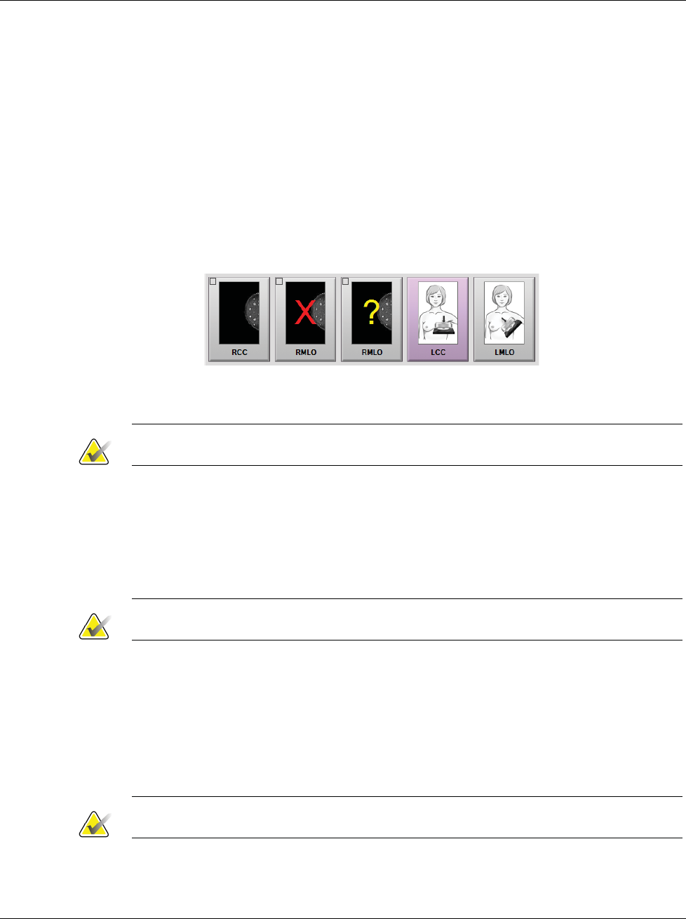
3Dimensions System User Guide
Chapter 6: Images
Page 72 MAN-05085-002 Revision 002
DRAFT Preview Copy-Generated May 30, 2018
4. When the x-ray is finished, the image appears on the Image Display monitor. The
Procedure screen automatically changes to the Tools tab.
Select one of the following options to complete the acquisition:
•Accept the image. The image transmits to output devices with all attributes.
•Reject the image. When the dialog box opens, select the reason for rejecting
the image. The Image Display screen closes. You can repeat the rejected view,
or select another view. If you select Reject, an "X" appears on the thumbnail
image.
•Pend the image. The image saves for future review. If you select Pend, a
question mark "?" appears on the thumbnail image.
Figure 43: Marked Images in a Procedure
5. Repeat steps 1 through 4 for each view.
Note
A manager user can configure the system to Auto-Accept or Auto-Pend new images.
6.3.1 Conventional Imaging Sequence of Events
1. Review the image after the exposure and add a comment, if necessary.
2. Accept, Reject, or Pend the image. A thumbnail image replaces the thumbnail view
in the Case Study area of the screen.
Note
A manager user can configure the system to Auto-Accept or Auto-Pend new images.
6.3.2 Tomosynthesis Imaging Sequence of Events
1. Wait for the image reconstruction to complete.
2. Review the projection images for motion.
3. Accept, Reject, or Pend the images. A thumbnail image replaces the thumbnail view
in the Case Study area of the screen.
Note
A manager user can configure the system to Auto-Accept or Auto-Pend new images.
3Dimensions System User Guide
Chapter 6: Images
MAN-05085-002 Revision 002 Page 73
DRAFT Preview Copy-Generated May 30, 2018
6.3.3 How to Accept a Rejected Image
If a rejected image is better than the new image, you can retrieve and use the old image.
Select the thumbnail image on the Procedure screen to review the image, then Accept the
image.
6.3.4 How to Accept or Reject a Pended Image
To accept or reject a Pended image, select the Pended thumbnail image, then select the
Accept button or the Reject button.
Note
A manager user can configure the system to Auto-Accept or Auto-Pend new images.
6.4 How to Correct and Reprocess Implant Images
You must correct the image if you acquire an implant or an implant displaced view
without the Implant Present button activated.
6.4.1 If the Image Is Not Accepted
Select the Implant Present button on the
Procedure screen to indicate an implant exists.
A check mark appears on the button and the
image reprocesses.
6.4.2 If the Image Is Accepted
1. Select the image.
2. Select the Implant Present button on the Procedure screen to correct the image. A
check mark appears on the button and the image reprocesses.
3. Select the Accept button to accept the changes.
Note
The corrected image is sent automatically to the selected output devices if the system is
set to send images when the Accept button is selected.
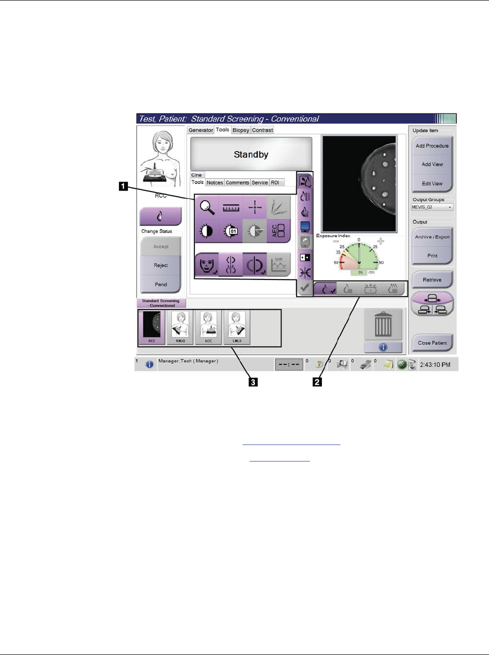
3Dimensions System User Guide
Chapter 6: Images
Page 74 MAN-05085-002 Revision 002
DRAFT Preview Copy-Generated May 30, 2018
6.5 How to Review the Images
Review of the images involves use of the thumbnails, image review tools, and display
modes.
Figure 44: Tools Tab (Tomosynthesis option shown)
Figure Legend
1. Image Review Tools - refer to Image Review Tools Tab on page 75.
2. Image Display Modes - refer to Display Modes on page 77.
3. Thumbnail Views and Thumbnail Images. Select any thumbnail image to display that
image on the Image Display monitor.
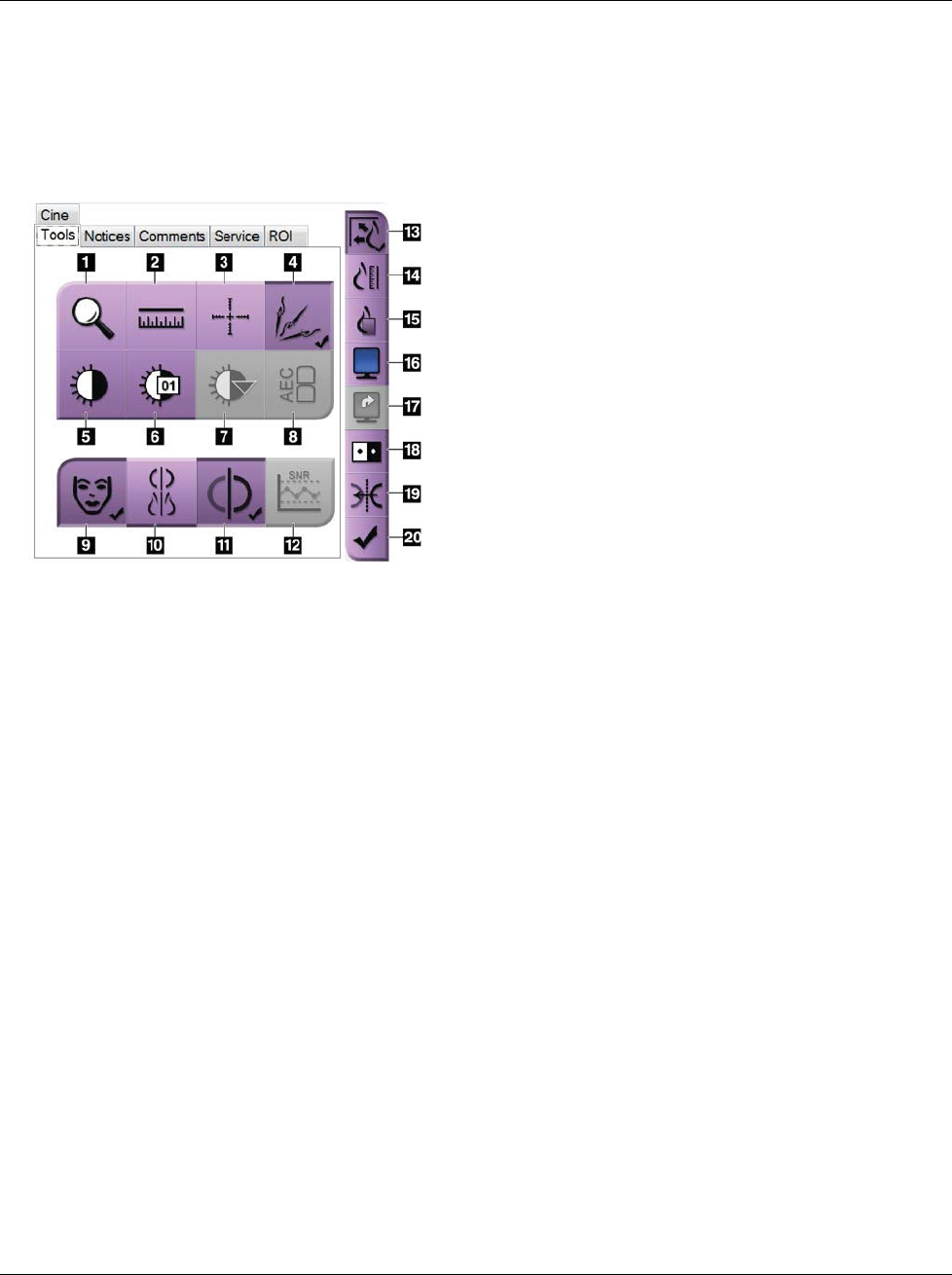
3Dimensions System User Guide
Chapter 6: Images
MAN-05085-002 Revision 002 Page 75
DRAFT Preview Copy-Generated May 30, 2018
6.5.1 Image Review Tools Tab
The Tools tab in the Procedure screen provides the image review tools. A check mark
appears on an active tool.
Figure 45: Image Review Tools
Figure Legend
1. The Zoom tool magnifies a section of the image.
2. The Ruler tool measures the distance between two
points.
3. The Crosshair tool displays a crosshair on the Image
Display screen.
4. The Demetalizer tool for processing tomosynthesis
images that contain metal objects.
5. The Window/Level tool changes the brightness and
contrast.
6. The Window/Level Fine Adjustment tool allows the
entry of specific window and level values.
7. The LUT Selection tool scrolls through available
Window/Level settings for a displayed image with LUTs
attached.
8. The AEC button displays the AEC Sensor areas used for
the exposure calculation. The sensor areas display on the
Image Display screen.
9. The Patient Information button activates the patient information display.
10. The Auto-Hanging button automatically hangs the currently selected study in a 4-up
configuration.
11. The Auto-Pairing button turns off auto-pairing for the currently selected image in a multi-up
configuration.
12. The SNR/CNR button calculates the signal-to-noise ratio and contrast-to-noise ratio on the ACR
Phantom.
13. The Fit-to-Viewport button fits the image within the image tile.
14. The True Size button displays the image in the actual size of the breast.
15. The View Actual Pixels button displays the image in full resolution.
16. The Multi-Up Display button selects the number of tiles to display.
17. The Image Tile Advance button sets the active Multi-Up tile.
18. The Invert Image tool changes blacks to whites and whites to black.
19. The Mirror button reverses (mirrors) the image.
20. The Tag for Print button tags the projection or reconstruction images of a tomosynthesis image to
print later.
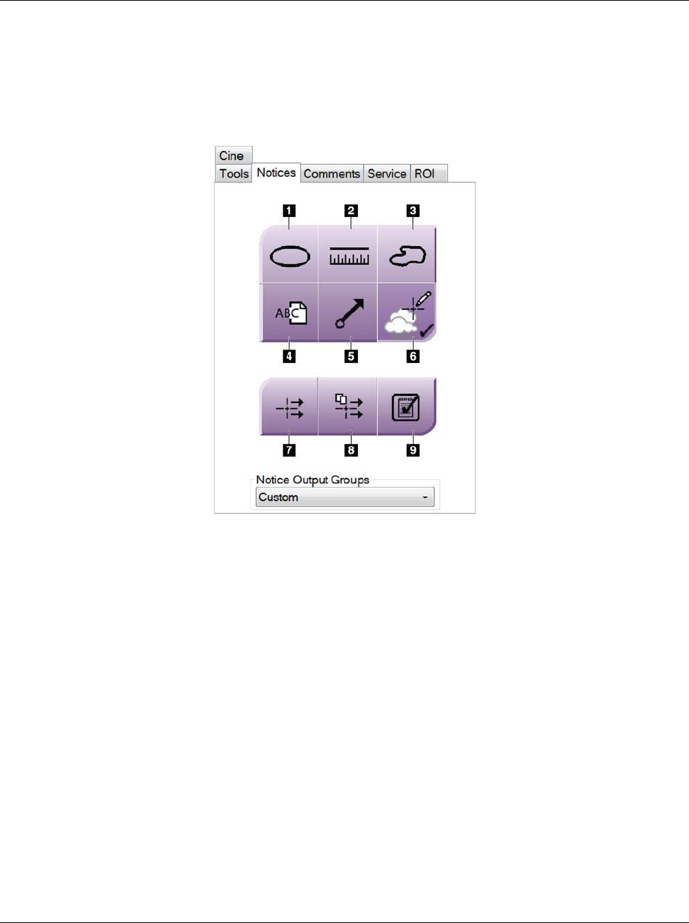
3Dimensions System User Guide
Chapter 6: Images
Page 76 MAN-05085-002 Revision 002
DRAFT Preview Copy-Generated May 30, 2018
6.5.2 Notices Tab
The tools on the Notices tab allow you to mark and annotate images and send notices
about the displayed image or procedure. The Notice Output Groups drop-down menu at
the bottom of the tab allows you to select the destination for the Notices.
Figure 46: Tools on the Notices Tab
Figure Legend
1. The Oval tool draws an oval marking on the image.
2. The Ruler tool measures the distance between two points.
3. The Freehand tool draws a freehand marking on the image.
4. The Text tool adds a text note to the image without a marking.
5. The Arrow tool draws an arrow marking on the image.
6. The Markings tool shows or hides markings and annotations on an image.
7. The Send Notice tool sends a notice for the current image to the selected
destination.
8. The Send All Notices tool sends all notices for all images in the opened procedure
to the selected destination.
9. The Viewed tool changes the Patient Notices status to viewed.
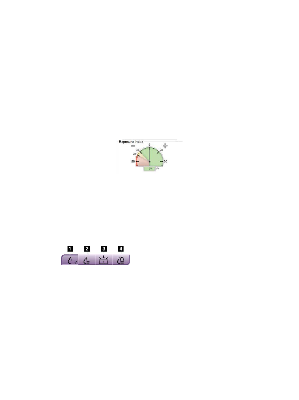
3Dimensions System User Guide
Chapter 6: Images
MAN-05085-002 Revision 002 Page 77
DRAFT Preview Copy-Generated May 30, 2018
6.5.3 Other Image Review Tools
Other Tabs
•Comments: Add comments to an image.
•Service: Mark an image for service use.
•ROI: Draw a Region of Interest on the Image Display monitor.
•Cine: Show a series of images as a movie (Tomosynthesis option).
Exposure Index
The Exposure Index is an image quality guide. When the Exposure Index indicates the
red or yellow area, review the selected image for noise and decide whether to reacquire
the image.
Figure 47: Exposure Index
Display Modes
Use the buttons in the Display Modes area of the screen to select the type of view to show
on the Image Display monitor. You can change between conventional, generated 2D,
projections, and reconstructions to show the combination images.
Figure 48: Display Modes
Figure Legend
1. Conventional button shows conventional images.
2. Generated 2D button shows a conventional 2D image
generated from the acquired tomographic image.
3. Projections button shows the 15° projection images.
4. Reconstructions button shows reconstructed slices.
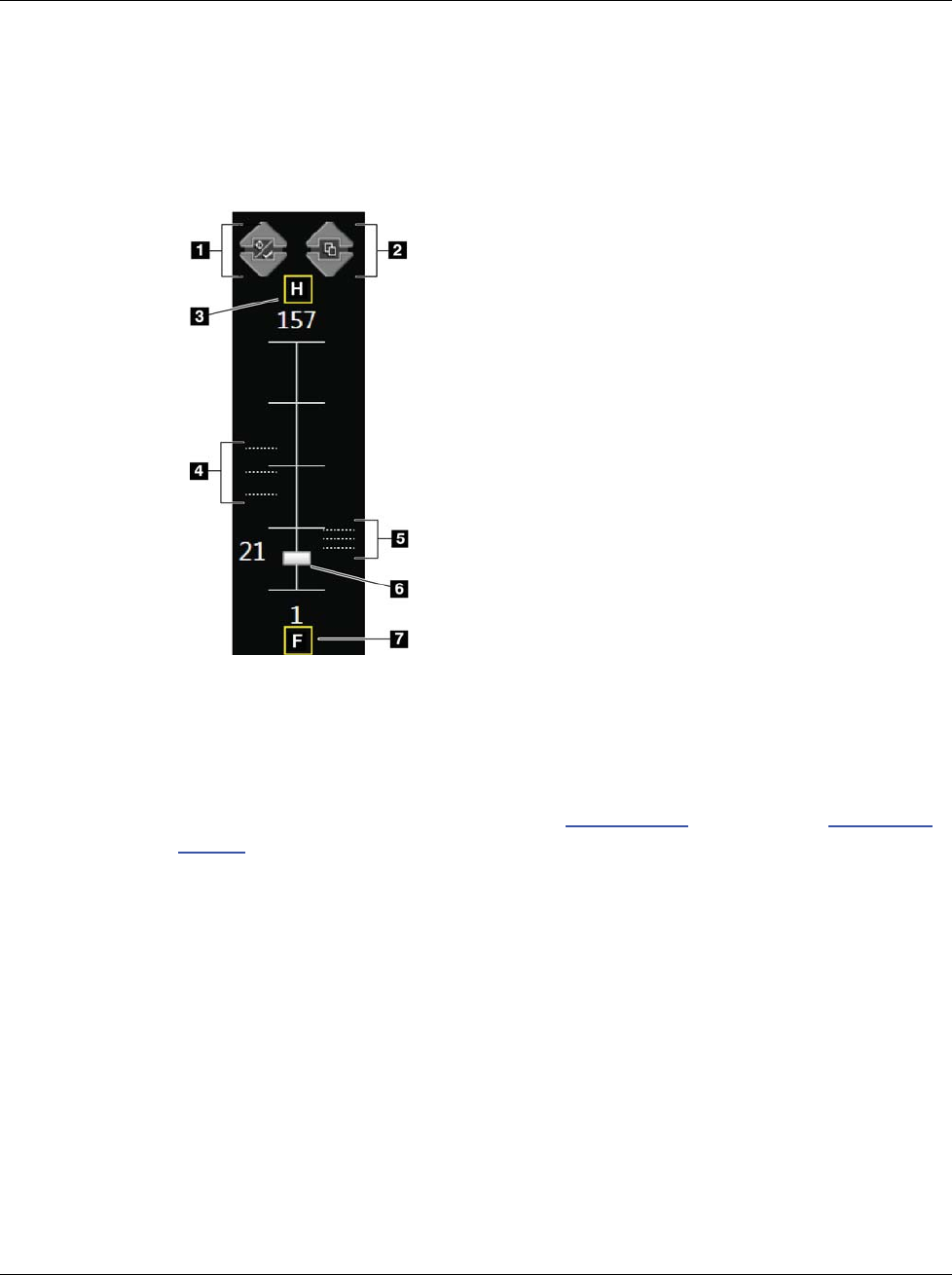
3Dimensions System User Guide
Chapter 6: Images
Page 78 MAN-05085-002 Revision 002
DRAFT Preview Copy-Generated May 30, 2018
6.5.4 Slice Indicator
The Slice Indicator on the Image Display monitor shows only on tomographic
reconstructions.
Figure 49: Slice Indicator
Figure Legend
1. Up and Down arrows let you change between slices that
contain a lesion target and slices that are tagged for printing.
2. Up and Down arrows let you change between slices that
contain notices.
3. “H” (anatomical reference to head direction)
4. Slices that contain targets or are tagged for printing.
5. Slices that contain notices.
6. Scroll bar moves through the slices of the reconstruction.
7. “F” (anatomical reference to foot direction)
6.6 How to Send the Images to the Output Devices
You can send the images to output devices or use the Archive/Export function to copy
images to temporary storage media. Refer to Output Groups on page 63 and On-Demand
Outputs on page 64 for instructions.
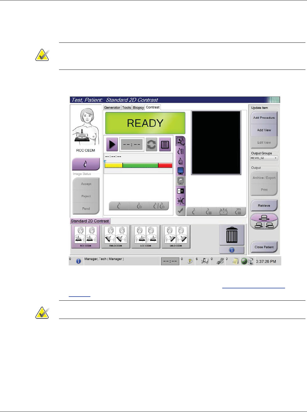
3Dimensions System User Guide
Chapter 6: Images
MAN-05085-002 Revision 002 Page 79
DRAFT Preview Copy-Generated May 30, 2018
6.7 How to Use I-View 2D Contrast
Note
Hologic configures some systems to meet specific requirements. Your system
configuration may not have all the options and accessories included in this manual.
1. Select the Contrast tab to access the I-ViewTM 2D Contrast (CE2D) function.
Figure 50: I-View 2D Contrast Screen
2. Set the contrast settings. For more information, refer to How to Set the Contrast
Defaults on page 119.
Note
When you set contrast information, it appears in the DICOM header of the images.
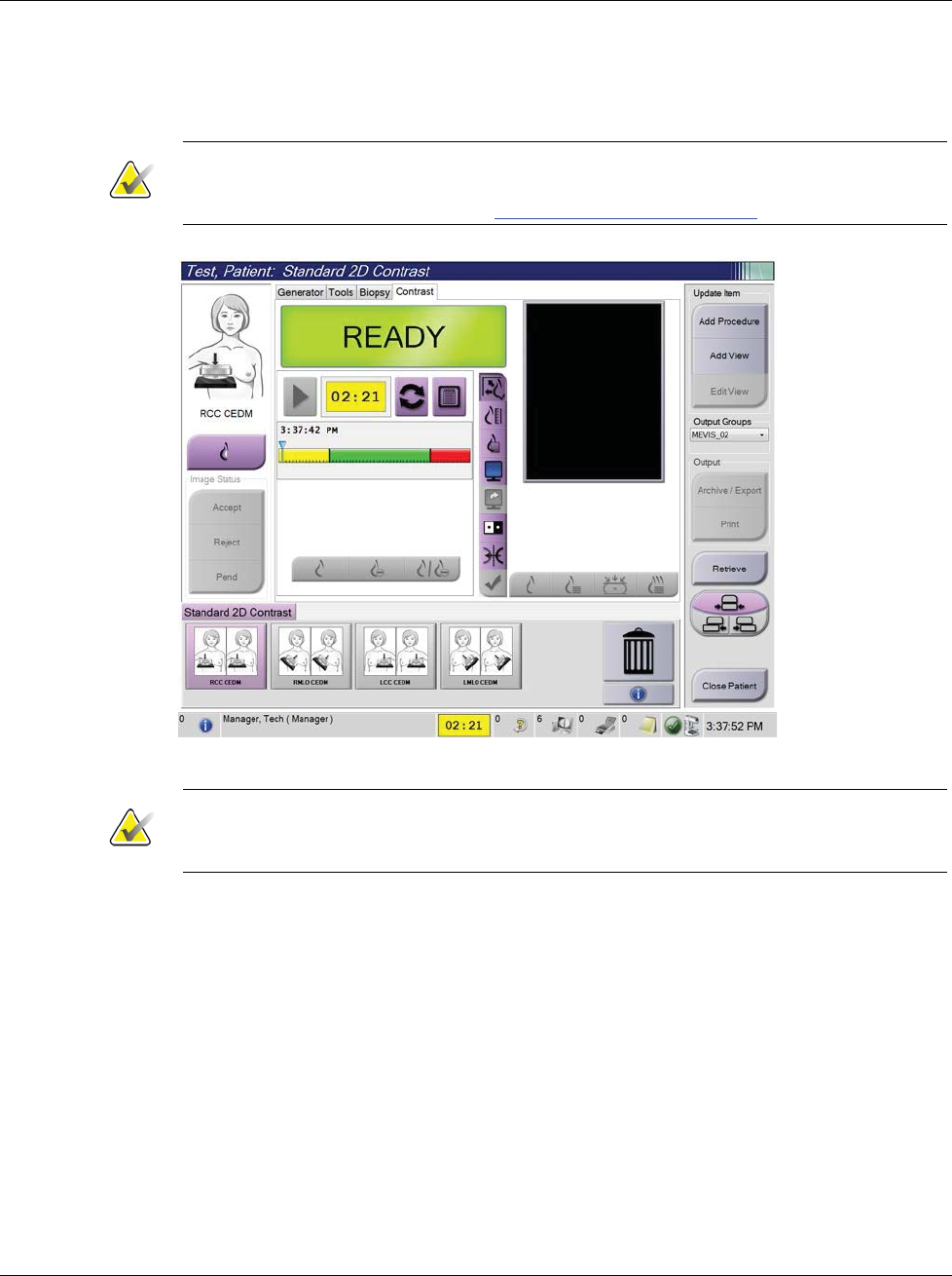
3Dimensions System User Guide
Chapter 6: Images
Page 80 MAN-05085-002 Revision 002
DRAFT Preview Copy-Generated May 30, 2018
3. To begin the contrast dose and start the timer, select the Start (arrow) button.
The timer begins in the Waiting Period, which appears with a yellow background.
Note
You can adjust the default length of time for the Waiting Period and Optimal Imaging
Period phases of the timer. Refer to How to Set the Contrast Defaults on page 119.
Figure 51: I-View 2D Contrast Screen, Waiting Period
Note
The timer function does not allow you to stop the timer, only to start and reset it. The
timer stops only when you exit the patient procedures.
After the Waiting Period, the timer begins the Optimal Imaging Period, which
appears with a green background.
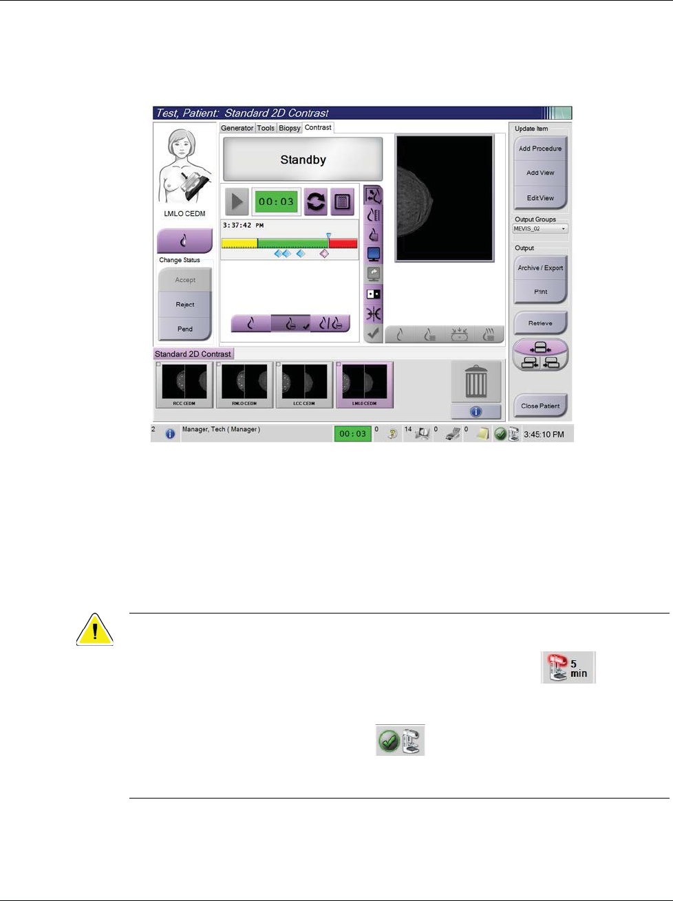
3Dimensions System User Guide
Chapter 6: Images
MAN-05085-002 Revision 002 Page 81
DRAFT Preview Copy-Generated May 30, 2018
4. Acquire the images during the Optimal Imaging Period.
After you acquire an image, a marker will appear below the timer.
Figure 52: I-View 2D Contrast Screen, Optimal Imaging Period
5. Select the low and high exposure buttons to acquire both low and high energy
images.
•Low: Conventional low-energy image
•Sub: Contrasted, subtracted image
•Low Sub: Shows both the low and sub screen images side-by-side in a split
screen.
Caution:
Using I-View 2D Contrast increases the recovery time the machine needs before more
images are acquired. When the x-ray tube status icon appears red , a
recommended wait time is shown. This wait time lets the x-ray tube temperature
decrease to avoid damage that can void the x-ray tube warranty. Always make sure
that the x-ray tube status icon is green before starting an I-View 2D Contrast
procedure. If the x-ray tube status icon turns red during a procedure, complete the
procedure quickly using the minimum number of exposures.
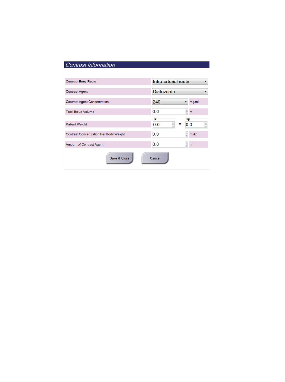
3Dimensions System User Guide
Chapter 6: Images
Page 82 MAN-05085-002 Revision 002
DRAFT Preview Copy-Generated May 30, 2018
6.7.1 How to Configure Contrast Settings
1. From the Contrast tab, select the Configure Contrast button to edit the contrast
settings. The Contrast Information dialog box opens.
Figure 53: I-View 2D Contrast Information
2. Use the drop-down menus to select the appropriate settings.
3. Enter data for the Contrast Concentration Per Body Weight field or the Amount of
Contrast Agent field. The other field automatically populates with the correct
information.
4. Click Save & Close.
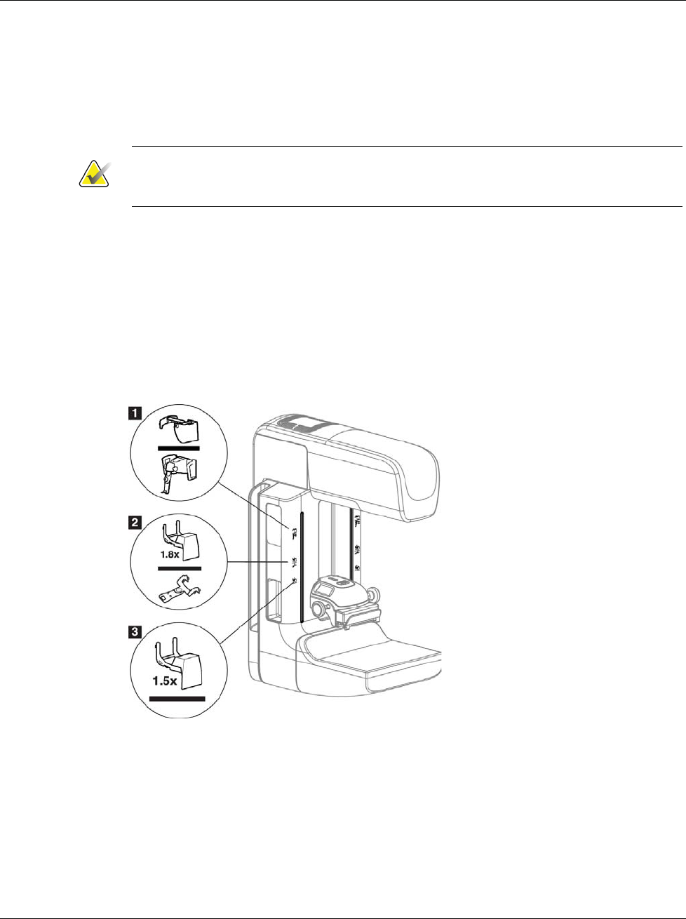
3Dimensions System User Guide
Chapter 7: Accessories
MAN-05085-002 Revision 002 Page 83
DRAFT Preview Copy-Generated May 30, 2018
7: Accessories
The system can perform screening or diagnostic applications with specified accessories.
This chapter describes how to use all possible system accessories.
Note
Hologic configures some systems to meet specific requirements. Your system
configuration may not have all the options and accessories included in this manual.
7.1 How to Install Accessories on the C-Arm
The Retractable Face Shield, Magnification Stand, and Localization Crosshairs are
installed in slots on the C-arm. The slots have labels with icons to indicate the accessory
that attaches in the slot. Each accessory has two lines. Align the accessory with the
related line on the C-arm. When the hook on the accessory is at the correct depth, the
second, thinner line aligns with the line on the C-arm. The next sections contain
installation instructions for each accessory.
Figure 54: C-arm Accessories
Figure Legend
1. Slot for Retractable Face Shield (Tomosynthesis option) or the Affirm® breast biopsy
guidance system (biopsy option)
2. Slot for 1.8x Mag Stand and Localization Crosshairs
3. Slot for 1.5x Mag Stand
Chapter 7
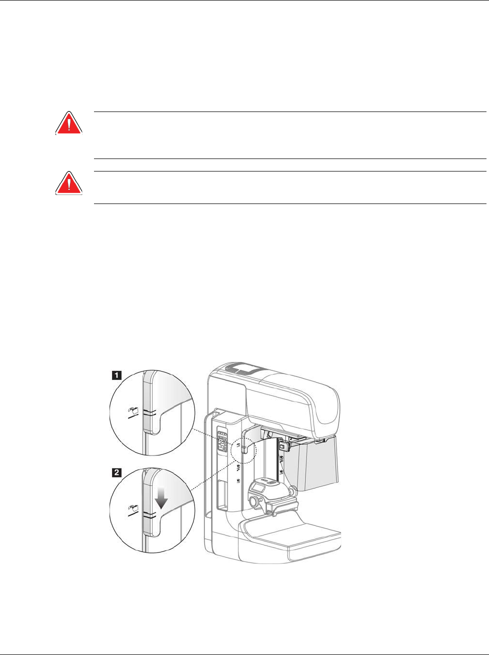
3Dimensions System User Guide
Chapter 7: Accessories
Page 84 MAN-05085-002 Revision 002
DRAFT Preview Copy-Generated May 30, 2018
7.2 Patient Face Shields
The Face Shield keeps the head and face of the patient away from the x-ray field during
the examination. Inspect the shield each day before use.
Warning:
The Face Shield must be attached for all exposures except magnification case
studies.
Warning:
The Face Shield does not protect the patient from radiation.
7.2.1 How to Install and Remove the Retractable Face Shield
To install the Retractable Face Shield:
1. Completely extend the Face Shield to the outer position.
2. Align the hooks of the Face Shield with the mounting slots on the C-arm, indicated
by a face shield icon.
3. Put the hooks on both sides of the Face Shield into the mounting slots on the C-arm.
The Unlock Lever (see item 1 in the following figure) is in the Up position.
4. Push the Face Shield to the down and locked position. The Unlock Lever is in the
Down position when the Face Shield locks.
Figure 55: Align the Retractable Face Shield on the C-arm
To remove the Retractable Face Shield:
1. Press and hold the Unlock Lever (see item 1 in the previous figure) in the Up
position.
2. Lift the Face Shield from the slots and remove from the C-arm.