Homerider Systems TRAK Wireless Sensor User Manual Manual Water Trak
Homerider Systems Wireless Sensor Manual Water Trak
UserManual.wiki
>
Homerider Systems
>
TRAK User Manual
>
Manual Water Trak
Contents
1.
Manual Fuel Trak
2.
Manual Propane Trak
3.
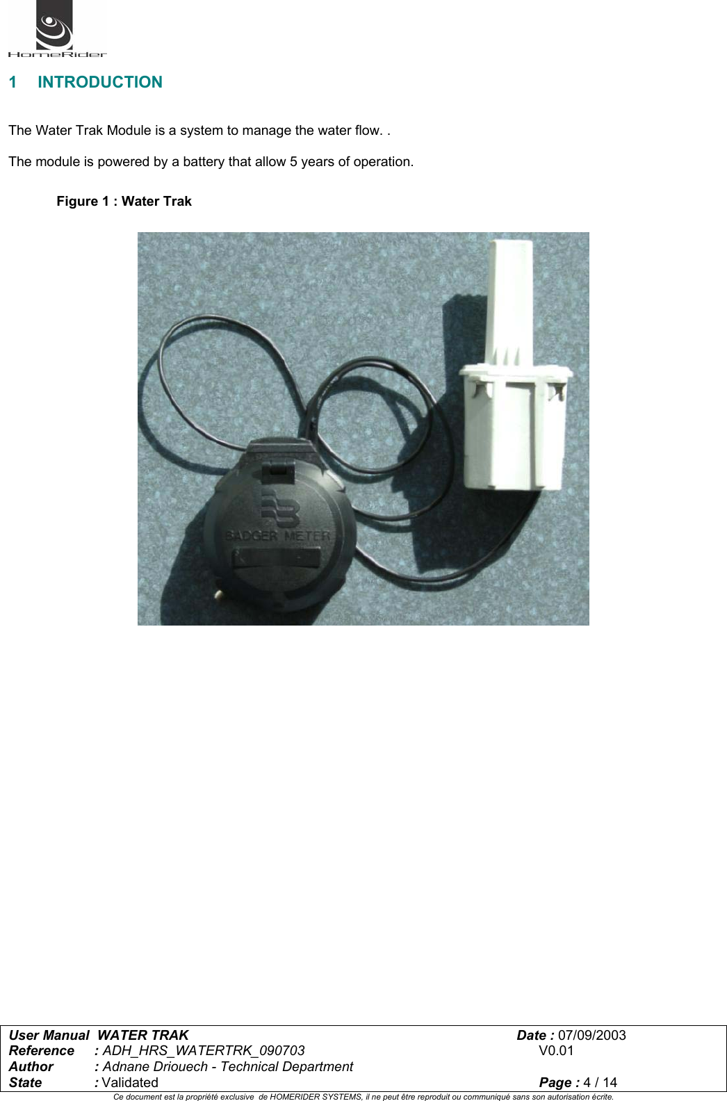
Manual Water Trak
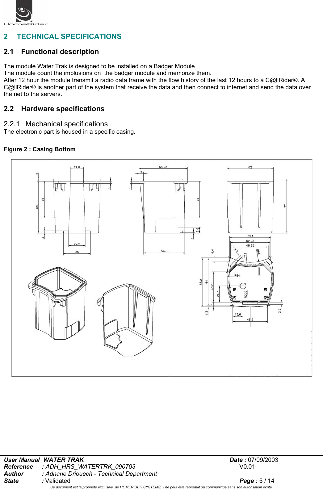
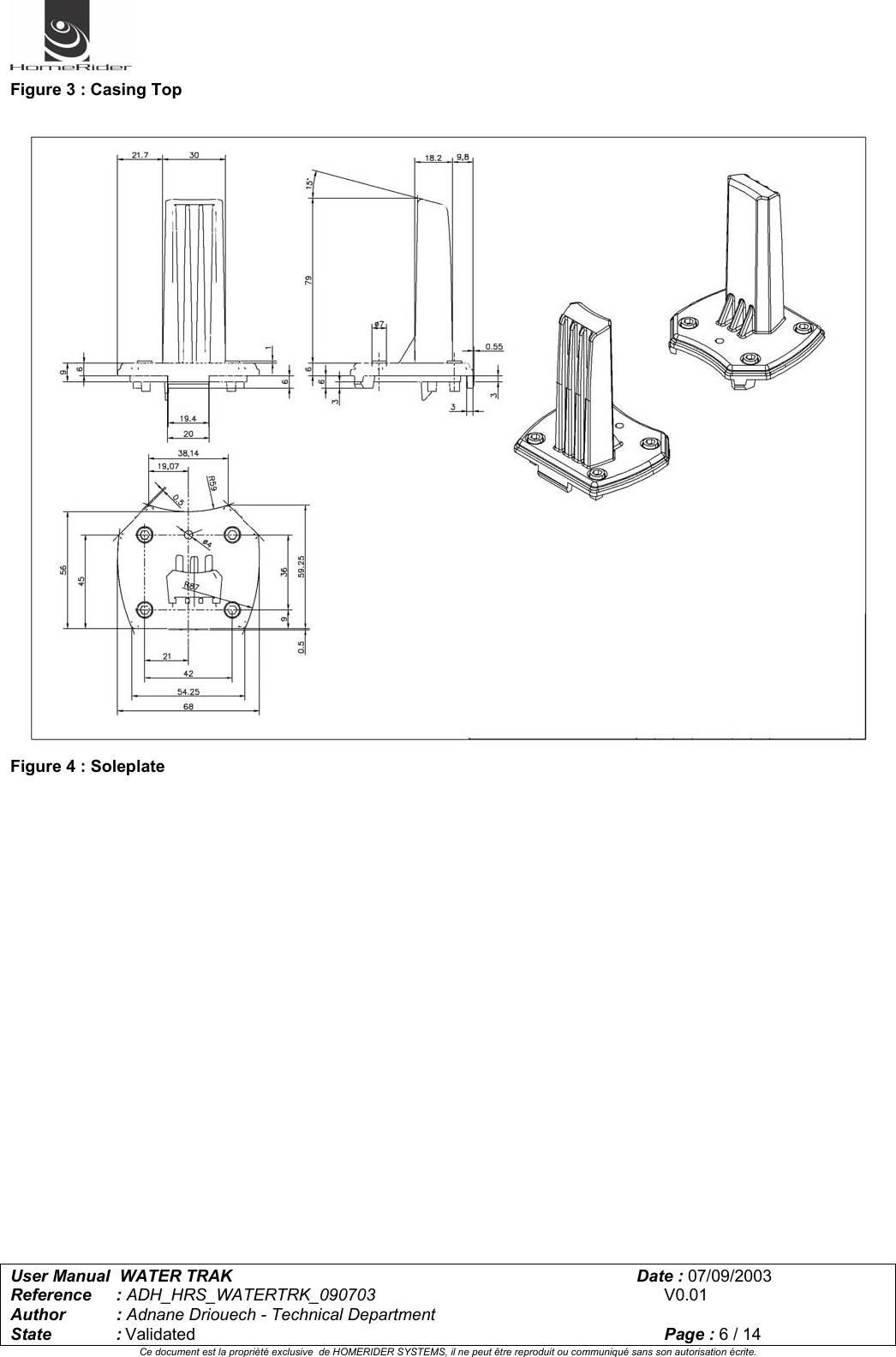
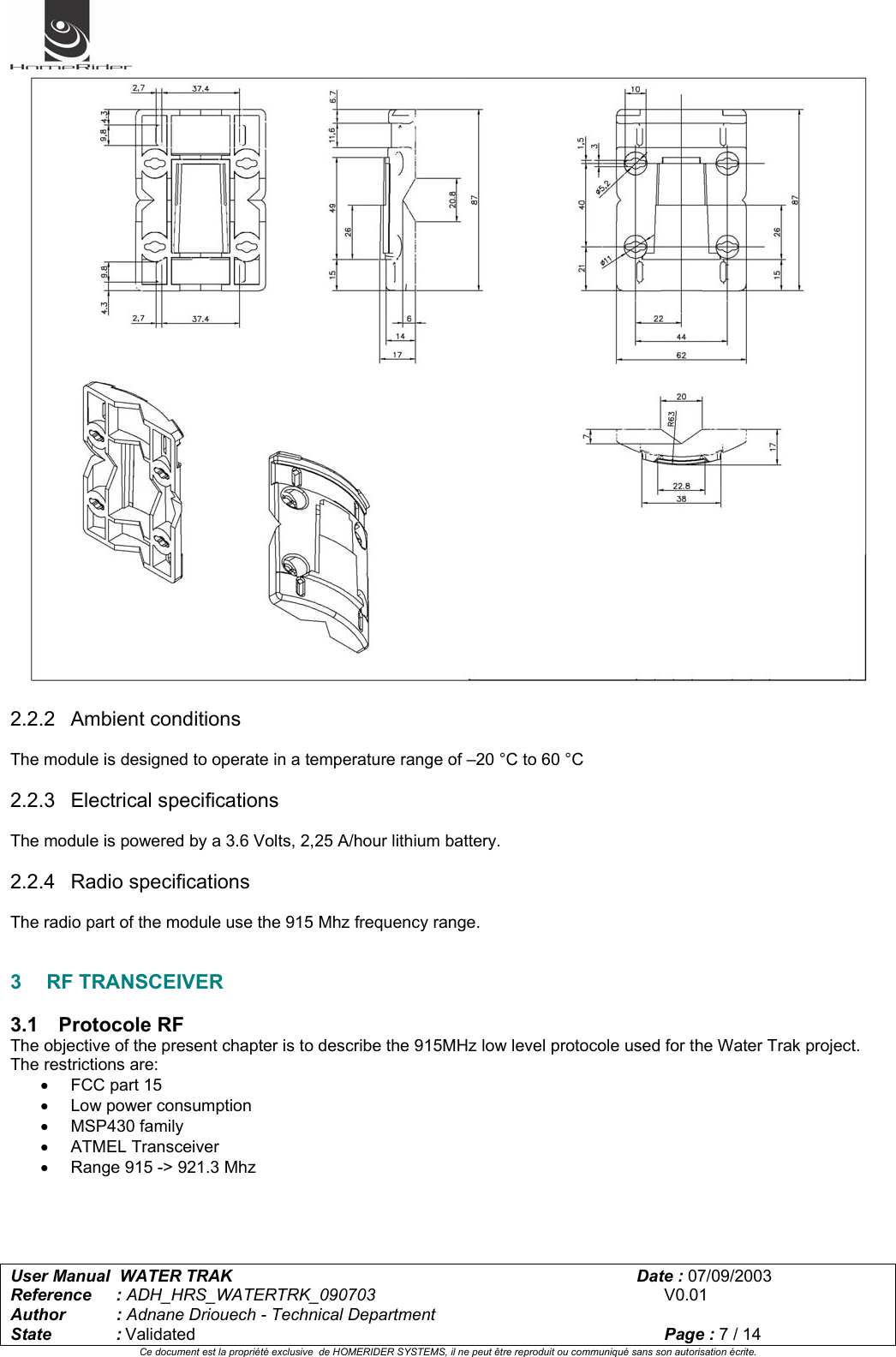
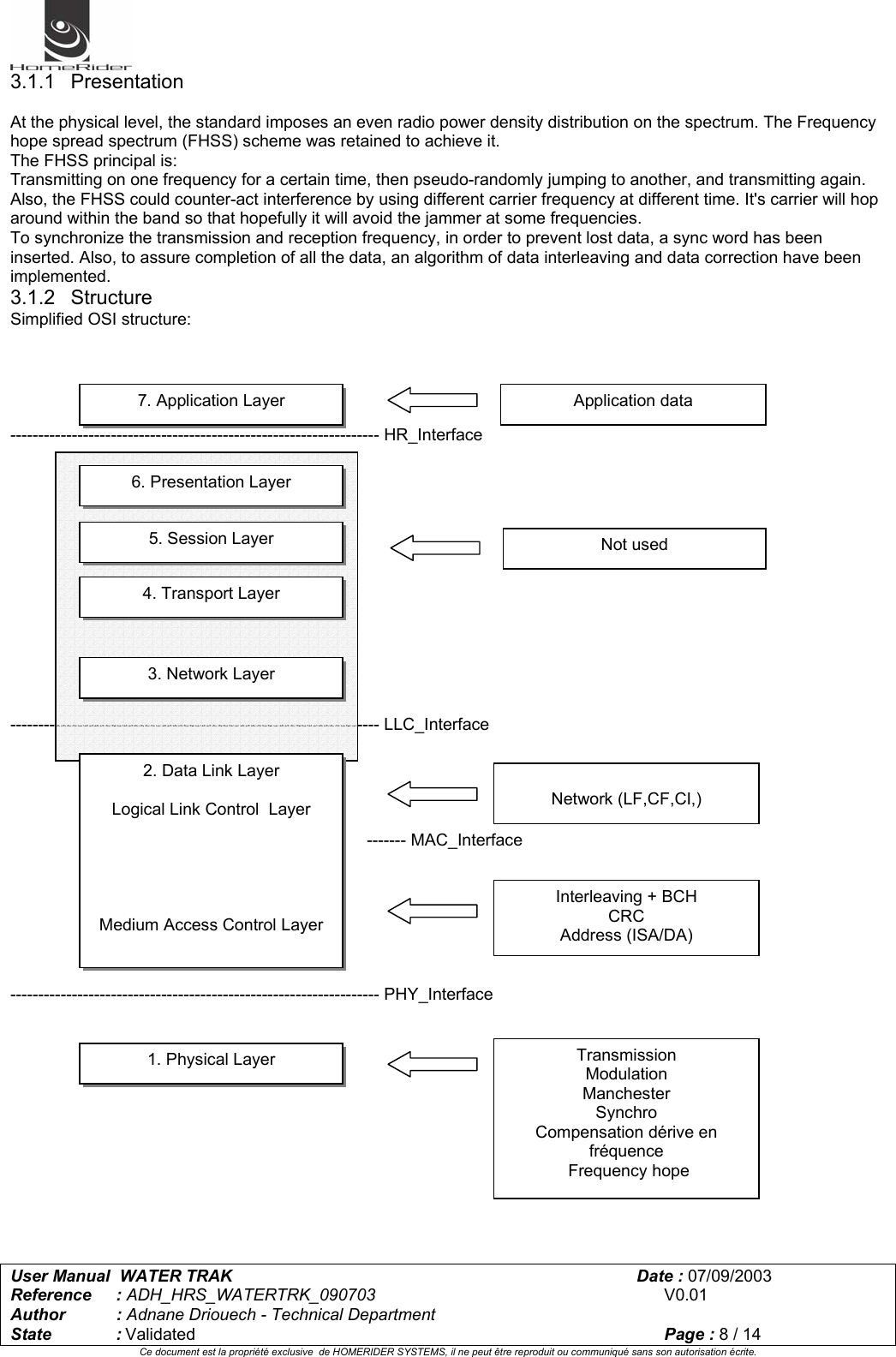
Manual Water Trak
Navigation menu
Upload a User Manual
Namespaces
Wiki Guide
HTML
PDF
Info
Views
User Manual
Discussion / Help
Navigation