Humax HS17 Digital Satellite Receiver(Headless DVR Server) User Manual Product Manual GenieAir 112216 SP 2Editsv1
Humax Co., Ltd. Digital Satellite Receiver(Headless DVR Server) Product Manual GenieAir 112216 SP 2Editsv1
Humax >
Contents
- 1. User Manuel
- 2. User Manual
User Manuel
P
RODUCT
M
ANUAL
–
G
ENIE
A
IR
TM
REVISION HISTORY
Version 1.3.0, 11/22/2016
AT&T DIRECTV, Inc. Proprietary and Confidential

Date
Author
Description of Change
Version
Sept 02,2016 S. Pardue First Draft 0.0.1 DRAFT
Sept 21, 2016
S. Pardue Initial Review with Eng 0.0.2 DRAFT
Oct 7,2016 S. Pardue Review with Eng and Care 0.0.3 DRAFT
Nov 18, 2016 S. Pardue Received Updated tech comm and Product Name 0.0.4 DRAFT
Nov 22, 2016 S.Pardue Updated draft with latest tech comm changes 0.0.5 DRAFT
Apr 8, 2016 S. Wrobel Reviewed Draft 0.0.6 DRAFT
Apr 13, 2016 S. Kobayashi Reviewed STB Features 0.0.7 DRAFT
Apr 13, 2016 G. Bicanek Reviewed HW Details 0.0.8 DRAFT
Apr 14, 2016 T. Brusehaver Reviewed Initial Installation 0.0.9 DRAFT
Apr 18, 2016 B. Toupin Reviewed UE Features 0.1.0 DRAFT
Apr 18, 2016 S. McNabb Reviewed Installation, Verification & Manage 0.1.1 DRAFT
Apr 18, 2016 S. Lee Reviewed Internal WVB 0.1.2 DRAFT
Apr 20, 2016 K. Kaushik Updated tech comm with changes 0.1.3 DRAFT
Apr 22, 2016 K. Kaushik -0- rev for Distribution 1.0.0
July 5, 2016 K. Kaushik Updates to Features 1.0.1 DRAFT
July 19, 2016 S. Wrobel Reviewed draft and made changes to Installation 1.0.2 DRAFT
July 22, 2016 S. Wrobel
S. McNabb
Reviewed draft and made updates to Activation, Manage &
Troubleshooting 1.0.3 DRAFT
July 25, 2016 S. Wrobel Reviewed draft and made additions to Installation 1.0.4 DRAFT
July 26, 2016 K. Kaushik Updated tech comm with changes 1.0.5 DRAFT
July 26, 2016 S. Wrobel Added new sections Menu UI & Feature Changes 1.0.6 DRAFT
July 26, 2016 K. Kaushik Updated tech comm with changes 1.0.7 DRAFT
July 29, 1016 K. Kaushik Updated tech comm with changes after Team Review 1.0.8 DRAFT
Aug 8, 2016 K. Kaushik Updated wireframes with screenshots 1.0.9 DRAFT
Aug 9, 2016 S. Wrobel Reviewed draft 1.0.10 DRAFT
Aug 15, 2016 S. Kobayashi Reviewed STB Features 1.0.11 DRAFT
Aug 16, 2016 T. Wood
T. Brusehaver
Reviewed draft
Reviewed BSL 1.0.12 DRAFT
Aug 17, 2016 M. Gabeler Lee Reviewed draft 1.0.13 DRAFT
Aug 19, 2016 P. Stein
M. Finegan
Reviewed draft
Reviewed Mobile Features 1.0.14 DRAFT
Aug 22, 2016 A. Rathert
C. She
Reviewed draft
Reviewed HW Features 1.0.15 DRAFT
REVISION HISTORY
Date
Author
Description of Change
Version
Aug 23, 2016 B. Toupin
D. Kuether
Reviewed UE Features
Reviewed draft 1.0.16 DRAFT
Aug 24, 2016 E. Mateik Reviewed draft 1.0.17 DRAFT
Aug 30, 2016 S. McNabb Reviewed draft 1.0.18 DRAFT
Aug 31, 2016 K. Hughes Reviewed Recording & Streaming Conflicts 1.0.19 DRAFT
Aug 31, 2016 K. Kaushik Updated tech comm with changes 1.0.20 DRAFT
Sep 1, 2016 K. Kaushik -0- rev for Distribution 2.0.0
Oct 14, 2016 K. Kaushik
S. Wrobel
S. McNabb
Updates to Resource Conflicts, Troubleshooting & Addressing
questions from 2.0 review 2.0.1 DRAFT
Nov 3, 2016 S. Wrobel Reviewed drafts and suggested edits to Installation &
troubleshooting 2.0.2 DRAFT
Nov 4, 2016 K. Kaushik
S. McNabb
Updated LED table with troubleshooting states 2.0.3 DRAFT
Nov 4, 2016 S. Wrobel Reviewed draft 2.0.4 DRAFT
Introduction
Before using the equipment, read the “Important safety instructions” of this manual. This manual outlines safeguards
information. The safety information contained in this manual was developed and provided solely by the manufacturer.
Safety Information is found in the back of this document
Product Manuals are intended to aid a customer in understanding the workings of the hardware
devices. This Product Manual will be posted online at ATT.com for customer access.
The purpose of this document is to communicate information associated with the Genie Air
TM
,
and to provide an overview addressing specific functions of the device.

Field Engineering Technical Communications are internal communiqués that aid in preparing
customer-facing departments ahead of product launches. Technical Communications comprise
much of the source documentation that is subsequently transformed into customer facing
materials such as scripts for Agent Call Center, troubleshooting guidelines, dot com web site
content, and other materials that are customized for various agent or technician audiences.
The purpose of this document is to communicate the technical information associated with the
Genie Air, and to provide an overview addressing how the new capabilities may impact the
customer, agent and field technician.
Any references to specifications developed by other departments defining this release are linked
here, if available.
Field Engineering staff wishes to aid and facilitate DIRECTV departments providing customer
service at all levels. Please send any requests or suggestions for any additional materials or
modifications to sswrobel@DIRECTV.com.

Product Manual – Genie Air
TM
Version 1.3.0 – 11/22/2016
Page i DIRECTV, Inc. Proprietary and Confidential
功
功功
功能變
能變能變
能變數代
數代數代
數代碼變
碼變碼變
碼變更
更更
更
C
ONTENTS
I. Overview ........................................................................................................................... 6
II. Hardware Information ........................................................................................................ 7
A. Front Panel .................................................................................................................. 7
B. Top Panel .................................................................................................................... 7
C. Rear Panel .................................................................................................................. 8
D. Side Panel ................................................................................................................... 9
E. Remote ........................................................................................................................ 9
F. Power Supply .............................................................................................................. 9
G. SIM Card and SIM Card Interface ...............................................................................10
H. Specifications .............................................................................................................10
III. Features ....................................................................................................................... 1211
A. Hardware Feature Comparison ............................................................................... 1211
B. Software Feature Comparison ................................................................................ 1312
IV. Minimum Requirements ................................................................................................ 1413
V. Installation .................................................................................................................... 1514
A. Genie Air
TM
Initial Installation .................................................................................. 1514
1. Physical Installation .......................................................................................... 1514
2. Genie Air
TM
Boot-Up & Activation ...................................................................... 1514
B. Client Installation .................................................................................................... 2019
1. Genie Wired Client ............................................................................................ 2019
2. Genie Wireless Client ....................................................................................... 2019
3. RVU TV / 4K RVU TV ....................................................................................... 2120
C. Add a Client Process .............................................................................................. 2120
D. Add External WVB .................................................................................................. 2322
E. Program Remote to Genie Mini Clients ................................................................... 2423
F. Program Remote to RVU TV using RF4CE to Server ............................................. 2423
VI. Manage (Replace & Remove) ...................................................................................... 2524
A. Replace Genie Air
TM
............................................................................................... 2524
B. Replace Client ........................................................................................................ 2524
C. Remove Client ........................................................................................................ 2524
D. Replace External WVB ........................................................................................... 2524
VII. Internet Configuration ................................................................................................... 2726
A. Never Connected Flow ........................................................................................... 2726
B. Previously Connected Flow .................................................................................... 2928
VIII. Menu and UI Differences .............................................................................................. 3029

Product Manual – Genie Air
TM
Version 1.3.0 – 11/22/2016
Page ii DIRECTV, Inc. Proprietary and Confidential
功
功功
功能變
能變能變
能變數代
數代數代
數代碼變
碼變碼變
碼變更
更更
更
A. Main Menu .............................................................................................................. 3029
B. My DIRECTV .......................................................................................................... 3029
C. Search & Browse .................................................................................................... 3029
D. Recordings ............................................................................................................. 3029
E. Extras ..................................................................................................................... 3029
F. Settings & Help -> Settings ..................................................................................... 3029
1. Settings & Help -> Settings -> Info & Test Screen Differences .......................... 3130
2. Settings & Help -> Settings -> Whole-Home Screen Differences ...................... 3433
3. Settings & Help -> Settings -> Reset Screen Differences .................................. 3635
4. Settings & Help -> Settings -> Remote Control Screen Differences .................. 3837
IX. Updates to Existing Genie OSDs .................................................................................. 3938
A. Video Bridge Connection Failed OSD ..................................................................... 3938
B. Wireless Connection Lost OSD .............................................................................. 3938
C. Internet Never Connected, Content Missing OSD ................................................... 3938
D. Program Requires Internet Connection OSD .......................................................... 3938
E. WVB Not Found OSD ............................................................................................. 3938
F. Connect to the Internet OSD................................................................................... 3938
X. Feature Differences ...................................................................................................... 4039
A. Transcoding ............................................................................................................ 4039
B. Recording & Streaming Conflicts ............................................................................ 4039
XI. Troubleshooting............................................................................................................ 4241
A. New OSD’s ............................................................................................................. 4241
1. Tilt Error OSD ................................................................................................... 4241
2. Thermal Warning OSD ...................................................................................... 4241
3. Bad AV Chip OSD ............................................................................................ 4241
B. System Test Diagnostic Codes ............................................................................... 4342
1. New Wireless IV Diagnostic Codes ................................................................... 4342
2. Updates to MoCA Test Errors ........................................................................... 4342
C. Symptoms .............................................................................................................. 4342
1. 5GHz SSID’s not listed ..................................................................................... 4342
D. Change to Existing Troubleshooting on Client / Server ......................................... 4342
1. Checks at Server .............................................................................................. 4342
2. No Servers Were Detected ............................................................................... 4342
3. Wireless Connection Lost ................................................................................. 4544
XII. LED Summary .............................................................................................................. 4746
A. Front Panel LEDs ................................................................................................... 4746

Product Manual – Genie Air
TM
Version 1.3.0 – 11/22/2016
Page iii DIRECTV, Inc. Proprietary and Confidential
功
功功
功能變
能變能變
能變數代
數代數代
數代碼變
碼變碼變
碼變更
更更
更
1. Status LED Table .............................................................................................. 4746
2. Wireless LED (Internal WVB Status) ................................................................. 4847
B. Top Panel LED – Add Client ................................................................................... 4847
C. Back Panel LEDs .................................................................................................... 4847
1. Power LED ....................................................................................................... 4847
2. MoCA LED ........................................................................................................ 4948
XIII. Appendix ...................................................................................................................... 5049
A. Steps To Connect Mobile Installation App to the WVB: .......................................... 5049
B. Federal Communications Commission Interference Statement ............................... 5150

Product Manual – Genie Air
TM
Version 1.3.0 – 11/22/2016
Page iv DIRECTV, Inc. Proprietary and Confidential
功
功功
功能變
能變能變
能變數代
數代數代
數代碼變
碼變碼變
碼變更
更更
更
FIGURES
Figure 1: Genie Air
TM
Front Panel ............................................................................................. 7
Figure 2: Genie Air
TM
Top Panel ................................................................................................ 7
Figure 3: Genie Air
TM
Rear Panel .............................................................................................. 8
Figure 4: Genie Air
TM
Side Panel ............................................................................................... 9
Figure 5: EPS17 Power Supply ................................................................................................. 9
Figure 6: SIM Card Front & Rear..............................................................................................10
Figure 7: Installation Satellite Setup Screen (Subject to Change)......................................... 1716
Figure 8: Genie Air
TM
Activation Screen (Subject to Change) ............................................... 1716
Figure 9: Genie Air
TM
Installation Verification SCreen (Subject to Change) .......................... 1817
Figure 10: Genie Air
TM
APG Guide Screen ........................................................................... 1817
Figure 11: Genie Air
TM
Data Feed Screens .......................................................................... 1918
Figure 12: Mobile Installation App - Installation Complete Screen (Subject to Change) ......... 1918
Figure 13: Connecting to WVB - Excellent Signal Strength Screen ...................................... 2019
Figure 14: Full Client Tracking - Add a Client Screen ........................................................... 2120
Figure 15: Activate your new Location Screen (Subject to Change) ..................................... 2221
Figure 16: Full Client Tracking - Guided Setup Complete Screen (Subject to Change) ........ 2221
Figure 17: Manage Clients - Stop Looking Screen (Subject to Change) ............................... 2322
Figure 18: Wireless Video Bridge Status Screen .................................................................. 2423
Figure 19: Remove Video Bridges Screen ........................................................................... 2625
Figure 20: Plug in Ethernet Cable Screen ............................................................................ 2726
Figure 21: Checking Connection Status Screen ................................................................... 2726
Figure 22: Internet Setup Complete Screen ......................................................................... 2827
Figure 23: Wireless Internet Confirmation Screen ................................................................ 2827
Figure 24: Select Wireless Network Screen ......................................................................... 2827
Figure 25: Genie Air
TM
Menu SCreen ................................................................................... 3029
Figure 26: Genie Server & Clients connected to a Genie Settings Screen ........................... 3130
Figure 27: Genie Air
TM
Client Settings Screen (Subject to Change) ..................................... 3130
Figure 28: Genie & Clients Connected to Genie - Info & Test Screen .................................. 3231
Figure 29: Genie Air
TM
Info & Test Screen ........................................................................... 3231
Figure 30: Genie Air
TM
Info Screen ....................................................................................... 3332
Figure 31: Manage Clients - Genie Client & Genie Server.................................................... 3433
Figure 32: Genie Air
TM
Manage Clients Screen .................................................................... 3433
Figure 33: Genie Air
TM
Manage Clients - Add Clients Screen ............................................... 3534
Figure 34: Genie Air
TM
Manage Clients - Add Clients Instructions Screen ............................ 3534
Figure 35: Receiver Reset - Genie Client & Server .............................................................. 3635
Figure 36: Genie Air
TM
- Reset Client Screen ....................................................................... 3635
Figure 37: Genie Air
TM
- Reset Client Confirmation SCreen ................................................. 3736
Figure 38: Genie Air
TM
- Reset Client to Default Screen ....................................................... 3736
Figure 39: Genie Air
TM
- Reboot Everywhere Screen ........................................................... 3837
Figure 40: Genie Air
TM
- Everywhere to Default Screen ........................................................ 3837
Figure 41: Resource Conflict - First Run Screen (Subject to Change) .................................. 4039
Figure 42: Resource Conflict - No Option or Cancel Recording Screen................................ 4140
Figure 43: Resource Conflict during Double-Play ................................................................. 4140
Figure 44: Tilt Error OSD Screen ......................................................................................... 4241
Figure 45: Android Settings Screen ...................................................................................... 5049
Figure 46: iOS Settings Screen ............................................................................................ 5150
Product Manual – Genie Air
TM
Version 1.3.0 – 11/22/2016
Page v DIRECTV, Inc. Proprietary and Confidential
功
功功
功能變
能變能變
能變數代
數代數代
數代碼變
碼變碼變
碼變更
更更
更
TERMINOLOGY
Term
Description
Client (RVU) Any RVU certified and DIRECTV approved device that can be
connected to the DIRECTV Genie Server (e.g. TV’s, Blu-ray Players,
etc.)
DIRECTV RVU
clients C31, C41, C41W, C51, C61K, C61W client
non-DIRECTV RVU
clients Samsung RVU TV, Sony RVU TV, PS3 etc.
DECA (CCK) DIRECTV Ethernet to Coaxial Adapter, also known as CCK, facilitates
an easy connection of a DIRECTV receiver with the customer provided
internet, using a single coaxial cable.
DECA (CCK) BB Broadband Ethernet to Coaxial Adapter
HDD Hard Disk Drive
LUI Local User Interface, Samsung RVU TV’s user interface, such as
“Picture”, “Dolby Digital”, “Captioning”, etc., independent of, but
accessed through the DIRECTV RUI.
MoCA Multimedia over Coax Alliance.
Protocol (RVU) A set of instructions defined to do a specific task. In case of RVU, the
instructions will allow non-DIRECTV clients (TV’s) to display and interact
with DIRECTV content without having a physical DIRECTV receiver in
every room.
RUI Remote User Interface, the DIRECTV UI which is accessed and
manipulated directly thru an RVU client.
RVU Standard used by manufacturers of consumer electronics to allow
entertainment devices within the home to share their content with each
other across a home network.
Server (RVU) The DIRECTV HR34, HR44, H44 (with HDD), HR54 HD DVR.
STB Set-top box or receiver.
WVB Wireless Video Bridge
RF4CE RF Remote control technology based on the ZigBee standard for
consumer electronics devices.

Product Manual – Genie Air
TM
Version 1.3.0 – 11/22/2016
Page 6 DIRECTV, Inc. Proprietary and Confidential
功
功功
功能變
能變能變
能變數代
數代數代
數代碼變
碼變碼變
碼變更
更更
更
I. O
VERVIEW
Welcome to AT&T’s DIRECTV video service. Genie Air
TM
is the next generation Genie Server,
satellite receiver that, provides breakthrough features, sophisticated integration and
enhanced customer experience.
Genie Air
TM
is a Headless Server. A Headless Server is a satellite receiver that has no local
display (no TV connection) on its own and is dedicated to providing services to its Genie
clients and RVU TV Clients.
Genie Air
TM
integrates Wireless Video Bridge (Gen 2) and transcoding (Mobile DVR)
capabilities. Genie Air
TM
will use eleven tuners (plus one Network Tuner), is capable of
Transponder Bonding and can support up-to Seven RVU clients simultaneously (two of
which can be 4K streams). Genie Air
TM
has built-in SWiM power and storage of 2TB. Genie
Air
TM
is compatible with all Genie clients and Wireless Video Bridge.
Product Manual – Genie Air
TM
Version 1.3.0 – 11/22/2016
Page 7 DIRECTV, Inc. Proprietary and Confidential
功
功功
功能變
能變能變
能變數代
數代數代
數代碼變
碼變碼變
碼變更
更更
更
II. H
ARDWARE
I
NFORMATION
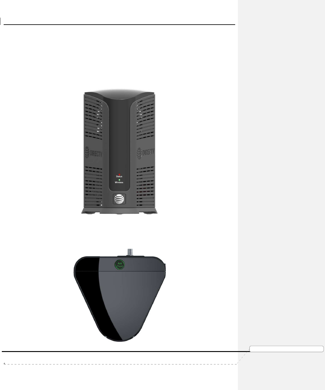
A. FRONT PANEL
• No Front-Panel Buttons.
• ”Status”: Multi-Color Status Indicator LED
• ”Wireless”: Multi-Color Wi-Fi Status Indicator LED (Internal WVB Status)
FIGURE 1: GENIE AIRTM FRONT PANEL
B. TOP PANEL
• ”Add Client”: Add Client Button with Green LED (At the Top)
FIGURE 2: GENIE AIRTM TOP PANEL
Product Manual – Genie Air
TM
Version 1.3.0 – 11/22/2016
Page 8 DIRECTV, Inc. Proprietary and Confidential
功
功功
功能變
能變能變
能變數代
數代數代
數代碼變
碼變碼變
碼變更
更更
更
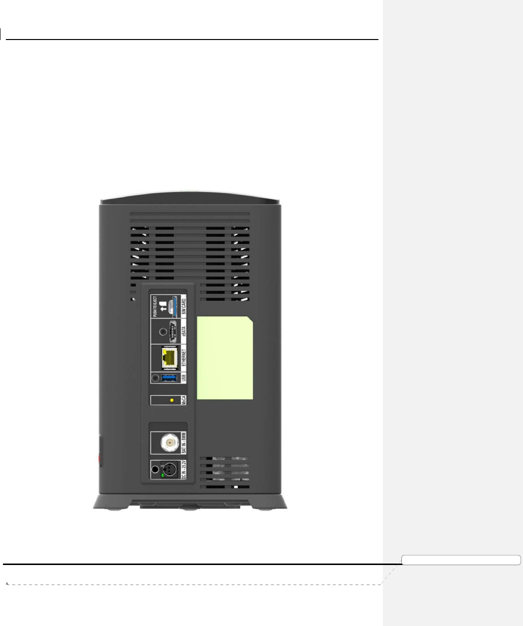
C. REAR PANEL
• “DC IN – 25.2V”: DC power connector with power indicator LED
• “SAT IN - SWM”: One satellite input coax connector (SWiM)
• “MoCA”: One MoCA status indicator LED
• “USB”: One USB 3.0 port
• “Ethernet”: One Ethernet port
• “eSATA”: One eSATA port
• “SIM CARD” with instruction to “PUSH TO EJECT”: One Conditional Access SIM
card slot - Do not access unless instructed by AT&T agent
FIGURE 3: GENIE AIRTM REAR PANEL
Product Manual – Genie Air
TM
Version 1.3.0 – 11/22/2016
Page 9
DIRECTV, Inc. Proprietary and Confidential
功
功功
功能變
能變能變
能變數代
數代數代
數代碼變
碼變碼變
碼變更
更更
更
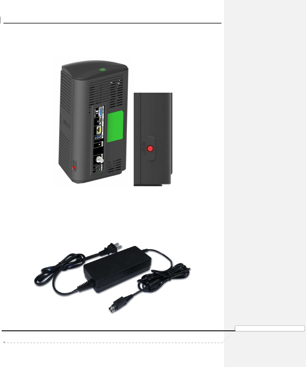
D. S
IDE
P
ANEL
• “RESET”: One red reset button - To be used only when instructed by AT&T agent
during troubleshooting
FIGURE 4: GENIE AIR
TM
SIDE PANEL
E. R
EMOTE
There is no remote with the Genie Air
TM
. However Genie Air
TM
has RF4CE. It will serve to
program remotes (RC71/RC72/RC73) for RVU TV clients
F. P
OWER
S
UPPLY
The Genie Air
TM
requires the EPS17 (DC 25.2V) External Power Supply.
FIGURE 5: EPS17 POWER SUPPLY
Product Manual – Genie Air
TM
Version 1.3.0 – 11/22/2016
Page 10 DIRECTV, Inc. Proprietary and Confidential
功
功功
功能變
能變能變
能變數代
數代數代
數代碼變
碼變碼變
碼變更
更更
更
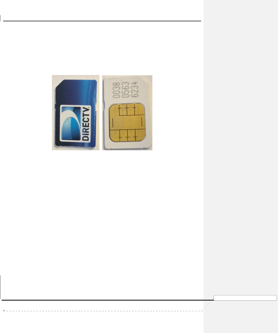
G. SIM CARD AND SIM CARD INTERFACE
Genie Air
TM
has a SIM card in the Rear Panel (Ref: Figure 3). The SIM card replaces the
Access Card. The SIM card will be pre-installed in the Genie Air
TM
. Similar to the Access
card, the SIM card is paired to the Genie Air
TM
(with a Receiver ID) and can be swapped out
with a new SIM card if necessary. The Card Number will be located on the back side of the
SIM. The way to insert the card is explained with an illustration near the SIM card slot.
FIGURE 6: SIM CARD FRONT & REAR
H. SPECIFICATIONS
• Memory : 3 GB DDR4, 8MB SNOR / 256MB NAND Flash
• Processor : BCM7366
• Storage : 2 TB SATA HDD
• Dimensions
• Height: 266 mm (10.47 inches);
• Width: 154 mm (6.06 inches);
• Depth: 142 mm (5.59 inches)
• Video & Audio Formats
• N/A
• Environmental Requirements
• Operating temperature: 32 to 122 ℉ ( 0
℃
to 50
℃
)
• Storage temperature (No Damage): -40 to 150 ℉ ( -40
℃
to 66
℃
)
• Relative humidity: 5-85% non-condensing

Product Manual – Genie Air
TM
Version 1.3.0 – 11/22/2016
Page 11 DIRECTV, Inc. Proprietary and Confidential
功
功功
功能變
能變能變
能變數代
數代數代
數代碼變
碼變碼變
碼變更
更更
更
• Mechanical Housing Design
• Genie Air
TM
needs to be placed in a Vertical position. Sensors will detect
when the orientation is not vertical. The Wireless LED will display
Flashing Yellow, and the clients will display a Tilt Error OSD.
Product Manual – Genie Air
TM
Version 1.3.0 – 11/22/2016
Page 12 DIRECTV, Inc. Proprietary and Confidential
功
功功
功能變
能變能變
能變數代
數代數代
數代碼變
碼變碼變
碼變更
更更
更
III. F
EATURES
• Genie Air
TM
is a Headless Server satellite receiver that has no output to a TV.
• Supports Wired, Wireless, 4K and RVU Clients
• Has built-in capability to connect to an internet Wi-Fi access point.
• Has Built-In Wireless Video Bridge Gen 2.
• Has Built-In Genie GO functionality.
• Capable of Transponder Bonding.
• Uses Eleven (11) Satellite Tuners (+ 1 Network Tuner).
• Support up-to Seven (7) RVU sessions simultaneously (two of which can be 4K
streams).
• Has built-in SWiM Power.
• Has internal storage of 2TB with expansion capability.
• Supports RF4CE Interface.
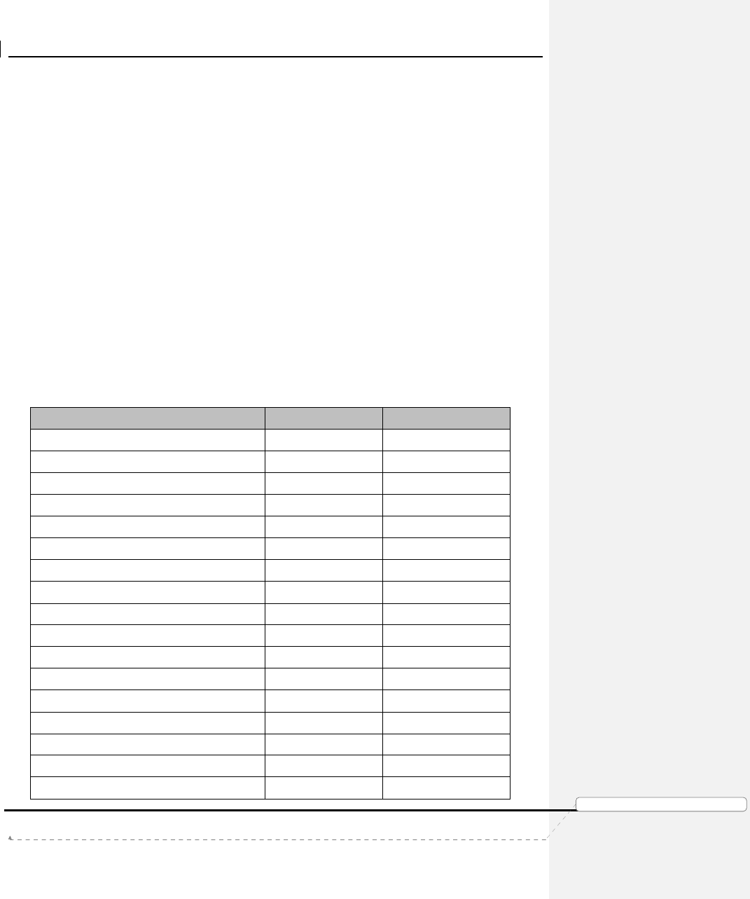
A. HARDWARE FEATURE COMPARISON
Feature
HR54
Genie Air
TM
Built in SWM Power (similar to PI21) Yes Yes
Tuners Used (Video + Network) 7+1 11 + 1
Audio / Video Output Yes No
Transponder Bonding Yes Yes
Built in WVB No Yes
Add Client Button (for Wireless Video) No Yes (At the Top)
Supports MoCA 1.1 Yes Yes
Supports MoCA 2.0 No Yes
Hard drive (Internal) 1TB 2TB
Hard drive expansion capable (eSATA) Yes Yes
Remote control compatible Yes No
Power Button Yes No
Recording LED Yes No
Menu/Guide/Arrows/Select/Res buttons
No No
Resolution LED No No
Reset Button Side Side
Access Card Yes No
Product Manual – Genie Air
TM
Version 1.3.0 – 11/22/2016
Page 13 DIRECTV, Inc. Proprietary and Confidential
功
功功
功能變
能變能變
能變數代
數代數代
數代碼變
碼變碼變
碼變更
更更
更
SIM Card No Yes
Receiver ID Yes Yes
USB 1 (USB 2.0) 1 (USB 3.0)
Power Supply EPS44 (12V) EPS17 (25.2V)
AM21 Support Yes No
B. SOFTWARE FEATURE COMPARISON
Feature
HR54
Genie Air
TM
4K ready (Receive, Record and
Distribute 4K content) Yes Yes
Display 4K content (local decode) No (distribute to
4K client) No (distribute to 4K
client)
Linear 4K Yes Yes
Push 4K Yes Yes
4K VOD Yes Yes
Number of 4K Linear/Recordings at
once 1 2
Total Number of recordings at once 5 7
Total number of registered RVU clients 8 8
Total number of active sessions (RVU,
MRV or Transcode Currently
Streaming)
3 7
Number of active 4K clients within total
number of clients 1 2
MRV Yes Yes
External WVB Compatible Yes Yes
AM21 Compatible Yes No
Built in Wi-Fi connection capability Yes Yes
2.4 GHz Wi-Fi Internet Interface Yes Yes
5 GHz Wi-Fi Internet Interface Yes No
Transcoding Support Yes Yes
Simultaneous SD Transcode 1 1
Simultaneous HD / 4K Transcode 0 0
Built in Transcoding Sync and Go Yes Yes
Built in Transcoding In Home / Out of
Home Streaming Yes Yes

Product Manual – Genie Air
TM
Version 1.3.0 – 11/22/2016
Page 14 DIRECTV, Inc. Proprietary and Confidential
功
功功
功能變
能變能變
能變數代
數代數代
數代碼變
碼變碼變
碼變更
更更
更
IV. M
INIMUM
R
EQUIREMENTS
All Minimum Requirements of Genie are applicable to Genie Air
TM
EXCEPT the Genie Air
TM
requires:
• DSWiM (DSWiM 13 module, SL3DS LNB, 3D2 LNB, 3D2RB LNB or 5D2RB LNB)
• Minimum of 11 available SWiM channels
• Minimum of 1 registered Client.

Product Manual – Genie Air
TM
Version 1.3.0 – 11/22/2016
Page 15 DIRECTV, Inc. Proprietary and Confidential
功
功功
功能變
能變能變
能變數代
數代數代
數代碼變
碼變碼變
碼變更
更更
更
V. I
NSTALLATION
A. GENIE AIR
TM
INITIAL INSTALLATION
The following steps are to be followed by an Installer for new installations (not replacement).
1. Physical Installation
Genie Air
TM
needs to be placed in a vertical position. Since Genie Air
TM
is a Headless
Server, a TV cannot be attached to it, and this provides placement flexibility.
Steps To Install Genie Air
TM
:
1) Install the ODU with a Digital SWiM LNB.
• Refer D-114 H44 Tech Comm for detailed information regarding
installation using the built-in SWiM power inserter.
2) If Internet is available (or will be available soon if known), place the Genie Air
TM
near the customer’s router and connect the Ethernet cable from the customer’s
router to the Genie Air
TM
. Genie Air
TM
will automatically connect to the Internet.
This is the preferred method. The minimum distance from other Wireless
devices is 4 feet (similar to present day wireless video and Wi-Fi guidance).
• Alternate Internet Connection – The Genie Air
TM
can also be Internet
connected using BB-DECA or Internal Wi-Fi (similar to HR44/54).
• Alternate Genie Air
TM
Location: Place the Genie Air
TM
in a location for
optimal signal between the built-in WVB and Wireless Client (per current
WVB placement guidance). Refer D-040 WVB Tech Comm for detailed
information.
3) Connect the coax cable from the wall plate to the Genie Air
TM
.
4) Connect the power cable to the Genie Air
TM
.
2. Genie Air
TM
Boot-Up & Activation
Once the Genie Air
TM
has Power, the Status LED on the front of the Genie Air
TM
goes
through various color state changes.
1) The Status LED remains OFF during boot-up (about 10 seconds). Note: This
initial LED Off state is subject to change before launch.
2) Once the Status LED turns Solid White (approx. 5 seconds), the Installer needs
to press the Add Client button located at the top of the Genie Air
TM
to force a
SWDL to the Genie Air
TM
(if necessary).
• SWDL over Broadband takes priority over SWDL over Satellite.
• The Status LED will change to Flashing White while the download occurs.
• Do not unplug or reset the Genie Air
TM
while it is in the Flashing White
LED state.

Product Manual – Genie Air
TM
Version 1.3.0 – 11/22/2016
Page 16 DIRECTV, Inc. Proprietary and Confidential
功
功功
功能變
能變能變
能變數代
數代數代
數代碼變
碼變碼變
碼變更
更更
更
• The SWDL duration via Satellite will be approx. the same as today while
the broadband download will be faster.
• Once the download completes, the Genie Air
TM
will reboot itself, and LED
sequence will go back to step 1 (Status LED Off for approx. 10 seconds,
Solid White for approx. 5 seconds)
• SWDL failure: In case of any issues during SWDL, the Status LED will
start Flashing Red. At this point the Genie Air
TM
will reboot itself and
attempt to download the software again.
3) The Status LED will turn Flashing Green (approx. 3-4 minutes), and the Add
Client button will begin Flashing Green (this indicates that the Installer’s Mobile
App and Wireless Clients can connect to the Genie Air
TM
).
4) The Installer can see the Initial setup screens by one of the following:
• On the Installer’s mobile device with the Mobile Installation App (that has
been previously configured), turn the Wi-Fi On. Then connect the
Installer’s mobile device to the Genie Air
TM
internal WVB wireless network
and launch the App. The role of the App is to allow the technician to setup
the Genie Air
TM
without a TV connected to it.
• If the Installer’s Mobile Device is unable to detect the WVB
Wireless Network, press the “Add Client” Button on the Genie
Air
TM
.
• This connection does not need Internet or cellular service.
• The steps for the one-time configuration of the Mobile Installation
App is explained in the Appendix.
• Connect a Wireless client to a TV to see the same installation screens
that will be displayed on the Mobile Installation App. If the screens don’t
appear, press the “Add Client” Button on the Genie Air
TM
• Connect a Wired Client to a TV and the Genie Air
TM
MoCA network to see
the same installation screens that will be displayed on the Mobile
Installation App.
5) The following Satellite Dish Setup (Verifying configuration) screen will be
displayed on the Mobile Installation App (or clients).
Product Manual – Genie Air
TM
Version 1.3.0 – 11/22/2016
Page 17 DIRECTV, Inc. Proprietary and Confidential
功
功功
功能變
能變能變
能變數代
數代數代
數代碼變
碼變碼變
碼變更
更更
更
FIGURE 7: INSTALLATION SATELLITE SETUP SCREEN (SUBJECT TO CHANGE)
• If the Genie Air
TM
is unable to detect the dish or auto-configure, the Status
LED will change to solid Yellow and the Satellite Dish Setup (Dish
configuration settings) screen will be displayed. The user needs to
manually configure Dish/Switch type before they can continue further.
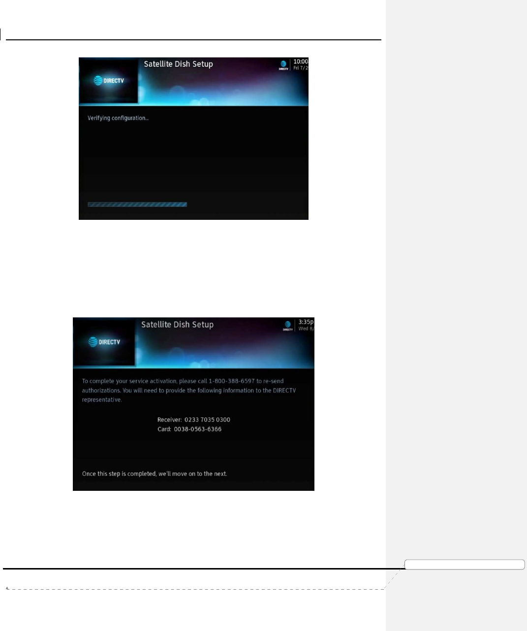
6) The Status LED then displays Solid Blue and Genie Air
TM
is ready for Activation.
Since Genie Air
TM
does not have any display on its own, there is no option to
switch language to Spanish.
FIGURE 8: GENIE AIRTM ACTIVATION SCREEN (SUBJECT TO CHANGE)
7) After Activation, the Satellite IV screen is displayed. The Status LED displays
Flashing Green.

Product Manual – Genie Air
TM
Version 1.3.0 – 11/22/2016
Page 18 DIRECTV, Inc. Proprietary and Confidential
功
功功
功能變
能變能變
能變數代
數代數代
數代碼變
碼變碼變
碼變更
更更
更
FIGURE 9: GENIE AIRTM INSTALLATION VERIFICATION SCREEN (SUBJECT TO CHANGE)
• If Satellite IV fails, the Status LED turns Solid Yellow. Troubleshooting
remains the same as present day install.
8) The Status LED continues to display Flashing Green as the Genie Air
TM
acquires the Advanced Program Guide with the download status as shown on
screen. Unlike the Genie’s, There is no option to “Continue” in the APG screen.
FIGURE 10: GENIE AIRTM APG GUIDE SCREEN
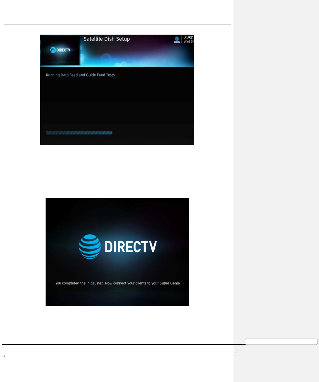
9) Once the APG data is 100% complete, the Genie Air
TM
runs the Data & Guide
Feed Tests. The Status LED remains Flashing Green.
Product Manual – Genie Air
TM
Version 1.3.0 – 11/22/2016
Page 19 DIRECTV, Inc. Proprietary and Confidential
功
功功
功能變
能變能變
能變數代
數代數代
數代碼變
碼變碼變
碼變更
更更
更
FIGURE 11: GENIE AIRTM DATA FEED SCREENS
• If there is an error found during the Data / Guide feed tests, the LED turns
Solid Yellow. Troubleshooting remains the same as present day install.
10) Once Initial Setup is complete, Status LED displays Solid Blue and Genie Air
TM
is ready to Add Client. The following screen is displayed only in the Mobile
Installation App. The Genie Mini clients and RVU TVs will display, the Add
Client screen (Refer – Add A Client section).
FIGURE 12: MOBILE INSTALLATION APP - INSTALLATION COMPLETE SCREEN (SUBJECT TO CHANGE)
Product Manual – Genie Air
TM
Version 1.3.0 – 11/22/2016
Page 20
DIRECTV, Inc. Proprietary and Confidential
功
功功
功能變
能變能變
能變數代
數代數代
數代碼變
碼變碼變
碼變更
更更
更
B. C
LIENT
I
NSTALLATION
The Genie Air
TM
must be Setup and Functioning before any RVU Clients can complete
installation. The following steps are to be followed at Initial Installation or when adding
clients post installation.
1. Genie Wired Client
The following are the Steps to Install the Genie Wired Client.
1) Connect the Genie Wired Client to the SWiM/MoCA network via coax.
2) Connect the Genie Client to a TV.
3) Plug the Genie client power cable into a power source and power on the Wired
Client.
4) Follow the Add A Client Process section below to add clients.
2. Genie Wireless Client
Since Genie Air
TM
has an in-built WVB no Site Survey will be performed.
The following are the Steps to Install Wireless Clients
1) Connect the Genie Wireless Client to a TV.
2) Plug the Genie client power cable into a power source and power on the
Wireless Client.
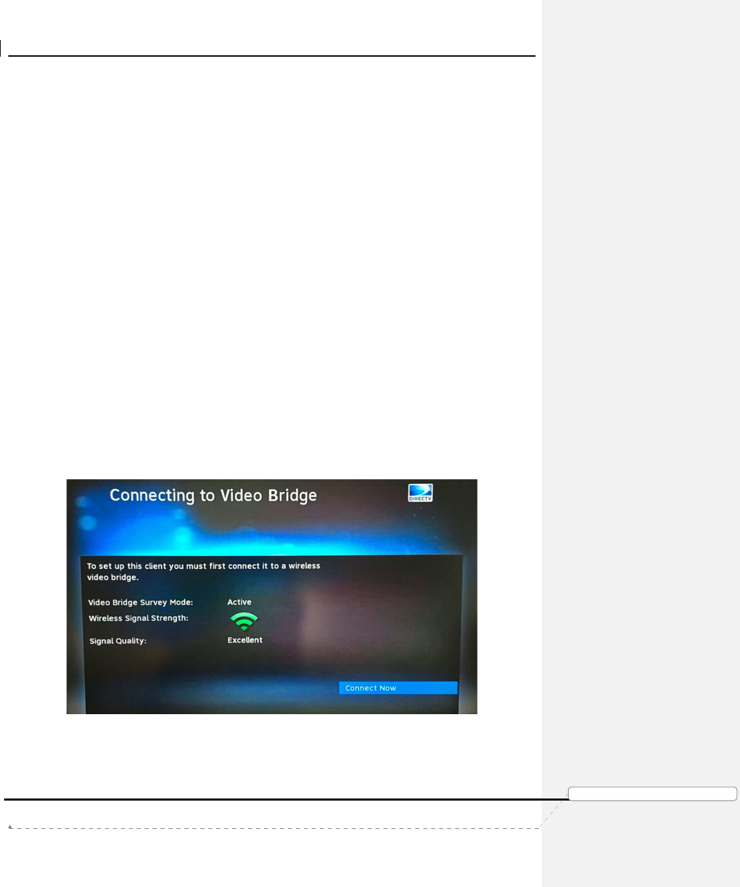
3) The Wireless client will try to connect to the server and the “Connecting to Video
Bridge” screen will be displayed.
• If Wireless Signal Strength is Green / Signal Quality is Excellent or Good,
the following screen is displayed, and the user can select “Connect Now”.
FIGURE 13: CONNECTING TO WVB - EXCELLENT SIGNAL STRENGTH SCREEN
• If Signal Strength/Quality is Yellow/Fair or Red/Poor, the Genie Air
TM
or
Wireless Client should be moved, or an External WVB should be added to
the install (follow normal guidance for WVB and Wireless Client
placement and troubleshooting).
Product Manual – Genie Air
TM
Version 1.3.0 – 11/22/2016
Page 21 DIRECTV, Inc. Proprietary and Confidential
功
功功
功能變
能變能變
能變數代
數代數代
數代碼變
碼變碼變
碼變更
更更
更
• If Video Bridge Survey Mode is “Inactive” and the Signal Quality is
“Waiting”, the user must press the Add Client button on the top of Genie
Air
TM
or on a previously connected client navigate to Menu -> Settings ->
Whole-Home -> Manage Clients -> Add Clients. The Add Client
(Discovery) mode is enabled for a maximum of 20 minutes (each time the
Add Client button is pressed), and it will time out. Once Signal Strength
becomes Excellent or Good, the user can select “Connect Now”.
4) The Wireless Client will connect to the Genie Air
TM
. Follow the Add A Client
Process section below to add clients.
3. RVU TV / 4K RVU TV
The following are the steps to install the RVU / 4K RVU TV client.
1) Connect the RVU / 4K RVU TV to the SWiM/MoCA network (Normal install
using the DECA or USB DECA)
2) Connect the power cable and turn on the TV.
3) Get to the DIRECTV Ready input.
4) Follow the Add A Client Process section below to add RVU / 4K RVU TV.
C. ADD A CLIENT PROCESS
The Add Client process will be different than current Genie process.
Full Client Tracking process will be used to Add Clients (Genie Air
TM
does not use Lenient
Mode). Full Client Tracking is documented in detail in the D-088 Goliath-Flower SWDL Tech
Comm (Refer the Appendix).
In Full Client Tracking, the users do not need the Server Pin to Add or Replace clients.
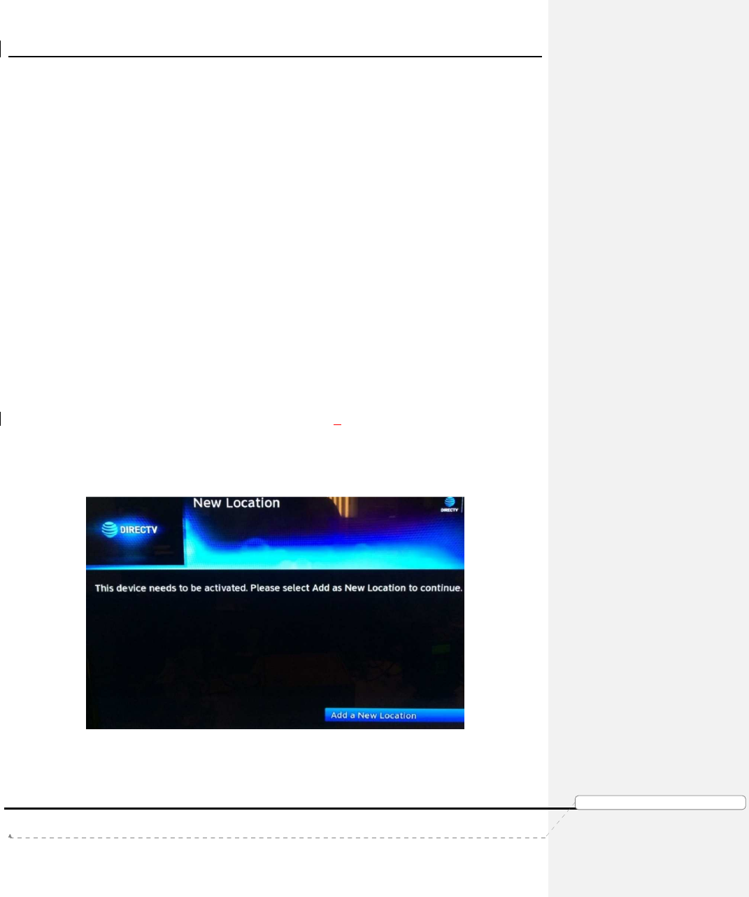
1) Once the clients are connected, the following screen is displayed in the client.
FIGURE 14: FULL CLIENT TRACKING - ADD A CLIENT SCREEN
2) The user needs to follow on-screen instructions to Add the client. Refer D-088
Goliath-Flower Tech Comm (Refer the Appendix). See “Add a Client when in
Lenient Mode or when in FCT mode” section III.B.3.b
Product Manual – Genie Air
TM
Version 1.3.0 – 11/22/2016
Page 22 DIRECTV, Inc. Proprietary and Confidential
功
功功
功能變
能變能變
能變數代
數代數代
數代碼變
碼變碼變
碼變更
更更
更
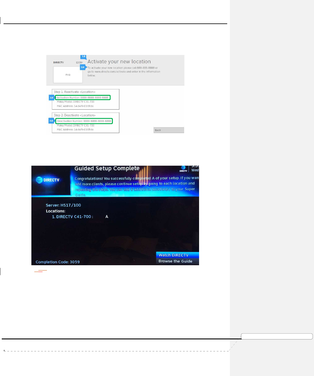
3) The “Activate Location” screen has been modified to include a new “Activation
Number”/“Deactivation Number” that will be used for future automated activation
process (This feature will not be available during pilot/product launch).
FIGURE 15: ACTIVATE YOUR NEW LOCATION SCREEN (SUBJECT TO CHANGE)
4) After the location has been added, the following “Guided Setup Complete”
screen is displayed at the client. The “Completion Code” is displayed in the
screen.
FIGURE 161615: FULL CLIENT TRACKING - GUIDED SETUP COMPLETE SCREEN (SUBJECT TO CHANGE)
5) After the first Client has been added the Status LED on the Genie Air
TM
turns
Solid Green.
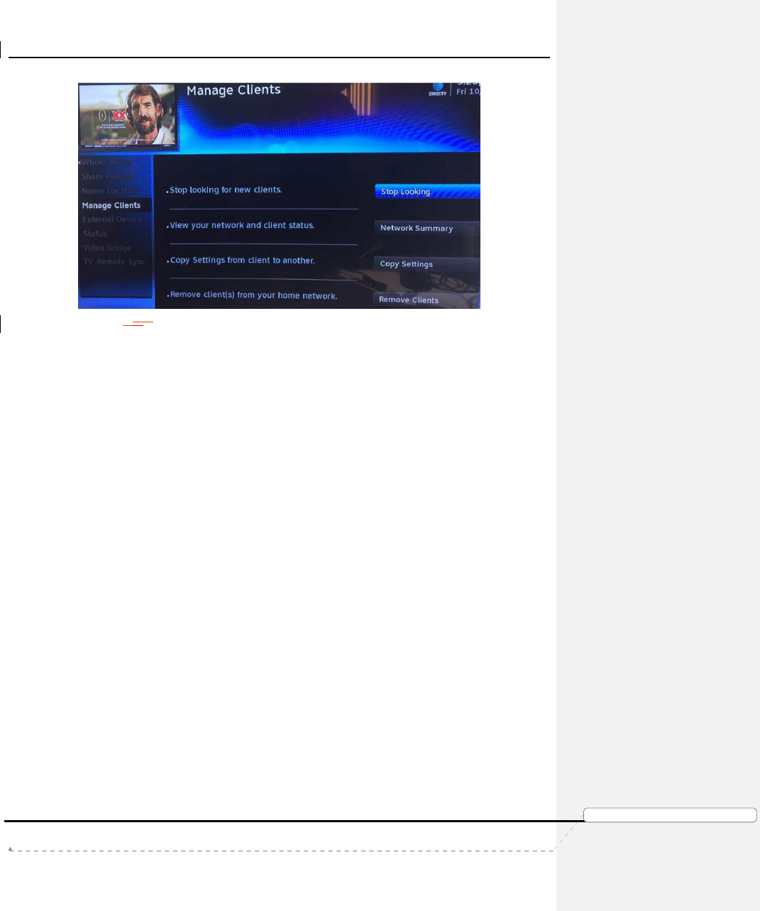
6) After all the clients have been added, the Add Client mode must be turned Off
by selecting Menu -> Settings -> Whole Home -> Manage Clients -> Stop
Looking.
Product Manual – Genie Air
TM
Version 1.3.0 – 11/22/2016
Page 23 DIRECTV, Inc. Proprietary and Confidential
功
功功
功能變
能變能變
能變數代
數代數代
數代碼變
碼變碼變
碼變更
更更
更
FIGURE 171716: MANAGE CLIENTS - STOP LOOKING SCREEN (SUBJECT TO CHANGE)
• If the user skips the Stop Looking step, the Add Client mode will
automatically timeout within 1 hour (during initial install) or 20 minutes (if
Add Client button was pressed).
D. ADD EXTERNAL WVB
Genie Air
TM
supports the configuration of an External WVB as a Wireless Extender to the
Internal WVB.
The following are the steps to install an External WVB.
1) Install the WVB in an optimal location as per current WVB placement guidance.
2) Ensure the Genie Air
TM
server is Turned On.
3) Ensure all the Wireless clients are turned Off (in standby).
4) Connect the power and coax cables to the external Wireless Video Bridge.
5) After the WVB boots up (WVB LED turns Solid Green / Blue), turn On the
Wireless clients.
6) The clients will display “A wireless video bridge has been found and configured
successfully”.
7) The client will automatically connect to the new WVB if it has a better signal
than to the Genie Air
TM
.
8) Ensure the Wireless clients have a Green LED and show video.
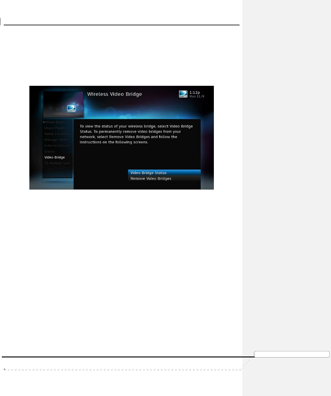
9) When the user selects Menu -> Settings -> Whole-Home -> Video Bridge ->
Video Bridge Status, the external WVB will be listed in addition to the internal
WVB.

Product Manual – Genie Air
TM
Version 1.3.0 – 11/22/2016
Page 24 DIRECTV, Inc. Proprietary and Confidential
功
功功
功能變
能變能變
能變數代
數代數代
數代碼變
碼變碼變
碼變更
更更
更
FIGURE 18: WIRELESS VIDEO BRIDGE STATUS SCREEN
E. PROGRAM REMOTE TO GENIE MINI CLIENTS
The procedure to program the Remote to Genie Mini remains the same as present day
install.
F. PROGRAM REMOTE TO RVU TV USING RF4CE TO SERVER
The procedure to program the Remote to the DIRECTV Ready RVU TVs is the same as the
present day (see D-137 Mimic SWDL Tech Comm for detailed programming steps). See
“DIRECTV Ready RVU TV Client Remote Control Programming” section III.A.2 in the Mimic
tech comm.
However since the Genie Air
TM
is Headless, during the steps to “Programming the Genie
Remote at the Genie Server” the user will be instructed to program the Remote using the
TV-Remote Sync option (Menu -> Settings -> Whole Home -> TV-Remote Sync). cannot be
used.

Product Manual – Genie Air
TM
Version 1.3.0 – 11/22/2016
Page 25 DIRECTV, Inc. Proprietary and Confidential
功
功功
功能變
能變能變
能變數代
數代數代
數代碼變
碼變碼變
碼變更
更更
更
VI. M
ANAGE
(R
EPLACE
&
R
EMOVE
)
A. REPLACE GENIE AIR
TM
The following are steps to be followed when the user needs to replace an old Genie Air
TM
with a new one.
1) Swap the old Genie Air
TM
with the new Genie Air
TM
.
2) Follow normal steps to Reset Connection (Reset to Default) on the Wireless
Client (if any).
3) Activate the new Genie Air
TM
as described in the Installation (Genie Air
TM
Boot-
Up & Activation) section V.A.2 above.
4) Follow the steps to add a client as described in the Installation (Add A Client)
section V.C above and pair all the clients to the new Genie Air
TM
.
B. REPLACE CLIENT
Full Client Tracking process is used to Add / Replace clients.
1) To replace a client, Follow the steps in the Installation (Client Installation)
section V.B above to swap the old client with the new client.
2) If using a Wireless Client, press the Add Client button at the top of the Genie
Air
TM
and select Connect Now on the wireless client.
3) Select Replace a Location.
4) Follow the Full Client Tracking steps to replace the Client. Refer D-088 Goliath-
Flower Tech Comm for detailed information (Refer the Appendix). See “Replace
an RVU Client when in Lenient Mode or when in FCT mode” section III.B.3.c
C. REMOVE CLIENT
The Genie Air
TM
should always have at-least one client connected to it. These steps are to
be followed only to remove the 2nd through 8th clients and not when replacing a client.
1) Physically remove the specific client.
2) From another client location select Menu -> Settings -> Whole-Home -> Manage
Clients -> Remove Locations.
3) Follow the Full Client Tracking steps to remove the client. Refer D-088 Goliath-
Flower Tech Comm for detailed information (Refer the Appendix). See “Delete
or Remove a Client when in Lenient Mode or when in FCT mode” section III.B.4
D. REPLACE EXTERNAL WVB
The Internal Video Bridge cannot be removed as it is built-into the Genie Air
TM
. If an External
WVB is configured to the network, the “Remove Video Bridges” option will be enabled.
The following are the steps to be followed when removing an External WVB.
1) Ensure the Genie Air
TM
server is has powered On.
2) Ensure all the Wireless clients are turned Off (in standby).
3) Physically remove the old WVB.
Product Manual – Genie Air
TM
Version 1.3.0 – 11/22/2016
Page 26 DIRECTV, Inc. Proprietary and Confidential
功
功功
功能變
能變能變
能變數代
數代數代
數代碼變
碼變碼變
碼變更
更更
更
4) Plug in the new WVB.
5) Power on all the Wireless clients.
6) Ensure the Wireless clients connected to the new WVB have a Green LED and
show video. Else troubleshoot Wireless clients as present day troubleshooting.
7) At any client (wired or wireless), select Menu -> Settings -> Whole-Home ->
Video Bridge -> Remove Video Bridges
FIGURE 19: REMOVE VIDEO BRIDGES SCREEN
8) Select the Checkbox for Wireless Video Bridge with "Not Found" after the
number, click Continue.
9) Press the Dash key. The OSD “You have successfully removed one Wireless
Video Bridge from your Whole-Home network” will be displayed.
Product Manual – Genie Air
TM
Version 1.3.0 – 11/22/2016
Page 27 DIRECTV, Inc. Proprietary and Confidential
功
功功
功能變
能變能變
能變數代
數代數代
數代碼變
碼變碼變
碼變更
更更
更
VII. I
NTERNET
C
ONFIGURATION
Genie Air
TM
connects to the Internet by leveraging the existing “Get Connected” process flow.
Genie Air
TM
performs better when connected in a Wired Broadband Connection. Once the
physical connection is made (Ethernet or BB DECA), the Genie Air
TM
should automatically
connect to the internet. If it does not get connected, the following steps need to be followed.
A. NEVER CONNECTED FLOW
The following are the steps to be followed when connecting a Genie Air
TM
to the Internet.
1) Connect the Ethernet cable to the Genie Air
TM
. The server will automatically
connect to the Internet. At the client press the Menu button and check if the
Genie Air
TM
is “Connected”. If it’s not Internet connected proceed to the next
step.
2) Select “Connect Now” at the client.
3) Once the user selects “Connect Now” the following “Plug in Ethernet Cable”
screen will be displayed. This screen is to promote the Wired broadband
connection. A graphic will be displayed to show the way to connect via Ethernet
cable.
FIGURE 20: PLUG IN ETHERNET CABLE SCREEN
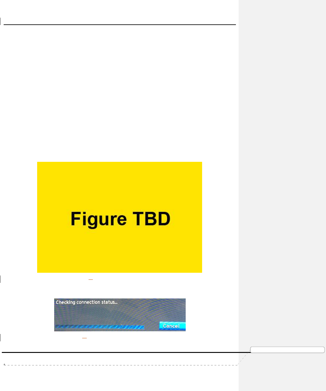
4) When the user plugs the Ethernet cable and selects “Check Connection”, the
following “Checking Connection Status” screen will be displayed.
FIGURE 21: CHECKING CONNECTION STATUS SCREEN
Product Manual – Genie Air
TM
Version 1.3.0 – 11/22/2016
Page 28
DIRECTV, Inc. Proprietary and Confidential
功
功功
功能變
能變能變
能變數代
數代數代
數代碼變
碼變碼變
碼變更
更更
更
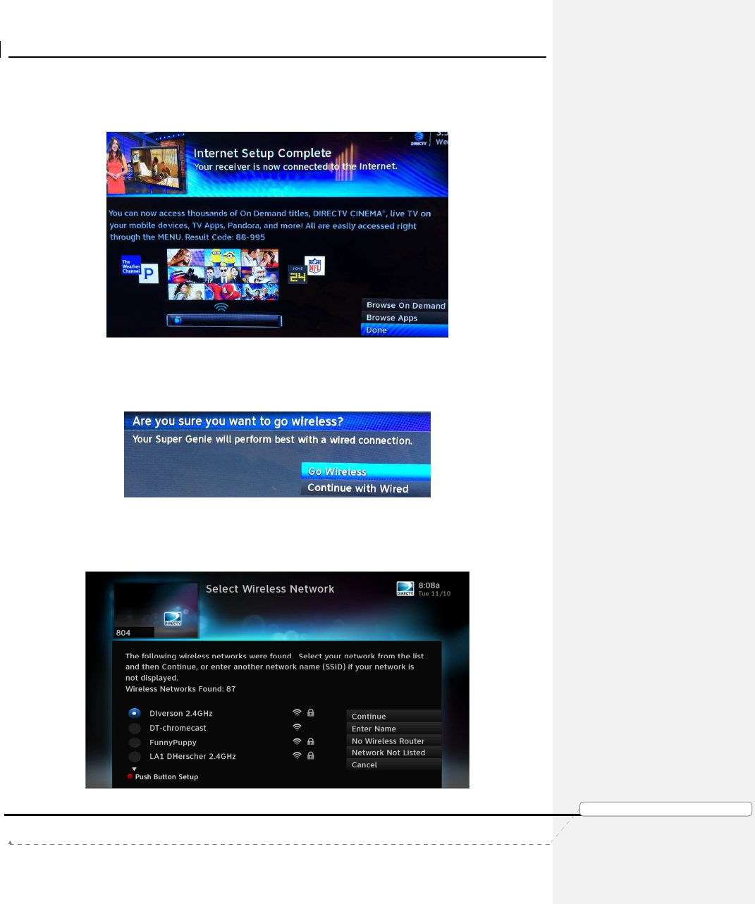
5) The Genie Air
TM
will check if its Internet connected. If it connects, the Internet
Setup Complete screen will be displayed else the “Checking Connection Status”
screen will continue to be displayed.
FIGURE 22: INTERNET SETUP COMPLETE SCREEN
6) If the user selects “Go Wireless Instead” at Figure 20, another Wireless Warning
confirmation screen will be displayed. This screen is used to re-confirm Wireless
broadband connection since Genie Air
TM
performs better in Wired broadband.
FIGURE 23: WIRELESS INTERNET CONFIRMATION SCREEN
7) If the user selects “Continue with Wired”, the previous “Plug in Ethernet Cable”
screen will be displayed (Ref: Figure 20). If the user selects “Go Wireless”, the
following “Select Wireless Network” screen is displayed.
FIGURE 24: SELECT WIRELESS NETWORK SCREEN

Product Manual – Genie Air
TM
Version 1.3.0 – 11/22/2016
Page 29 DIRECTV, Inc. Proprietary and Confidential
功
功功
功能變
能變能變
能變數代
數代數代
數代碼變
碼變碼變
碼變更
更更
更
8) The user can select the desired Wireless Network to join and proceed with the
exiting Get Connected Flow. For detailed information refer D-140 Neo SWDL
Tech Comm.
B. PREVIOUSLY CONNECTED FLOW
1) If the Genie Air
TM
was previously Internet connected, the “Reconnect Now”
screen will be displayed.
2) When the user selects “Reconnect Now”, the “Is your Internet connection
working” screen will be displayed (current existing Get Connected Flow).
3) When the user selects Yes, the Plug in Ethernet Cable screen will be displayed
(Ref: Figure 20). The purpose is to redirect the user to prefer Wired Internet
over Wireless connection.
4) Follow the same steps as in Never Connected flow to connect the Genie Air
TM
to
the Internet.
Product Manual – Genie Air
TM
Version 1.3.0 – 11/22/2016
Page 30 DIRECTV, Inc. Proprietary and Confidential
功
功功
功能變
能變能變
能變數代
數代數代
數代碼變
碼變碼變
碼變更
更更
更
VIII.
M
ENU AND
UI
D
IFFERENCES
Genie Air
TM
is a headless server and has no local display on its own. All the Server
information will be displayed on each RVU Clients. The screens that are displayed on a
client connected to Genie Air
TM
are different from the present screens in the Genie server
and clients connected to a Genie.
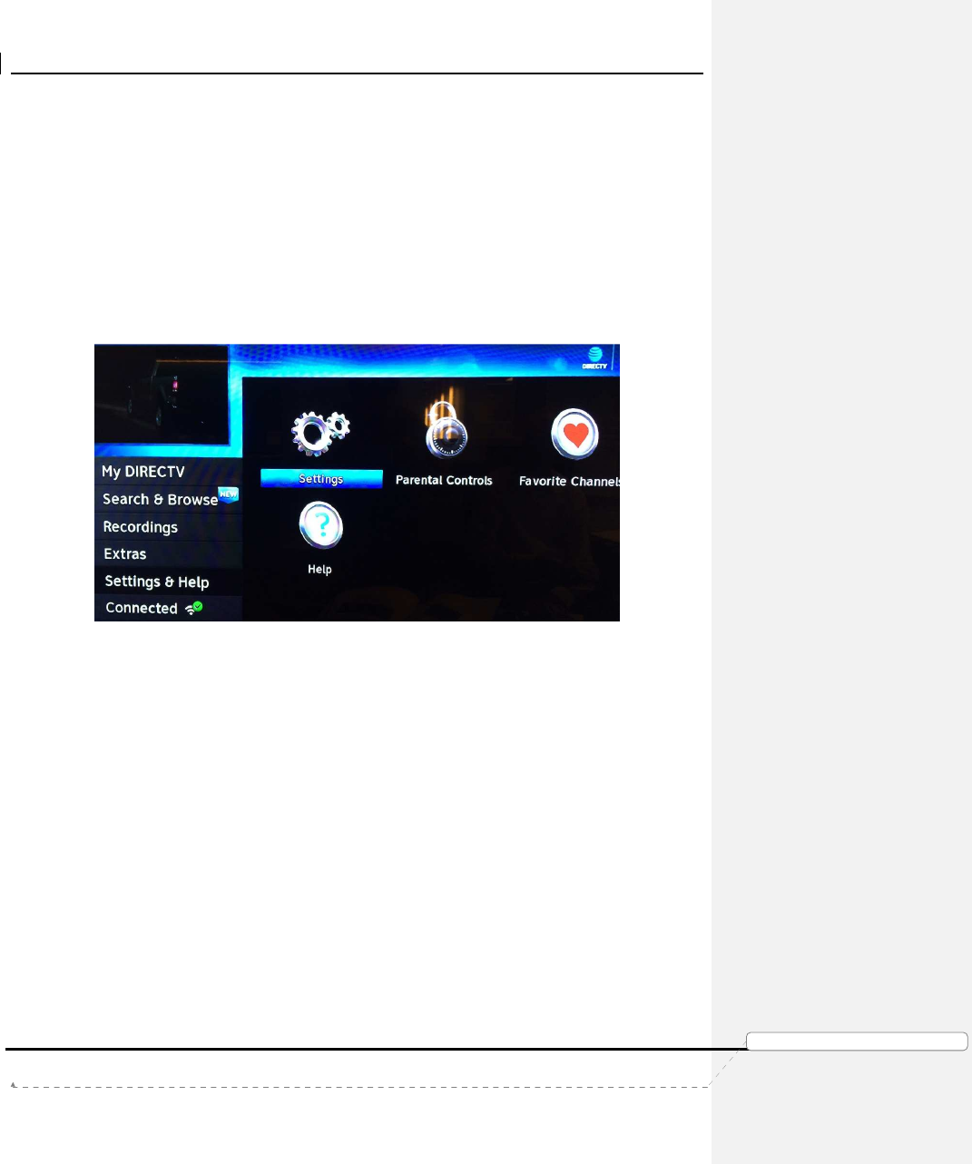
A. MAIN MENU
When the user selects the Menu button, the same Menu screen is displayed on the Genie,
clients connected to the Genie and clients connected to the Genie Air
TM
. The Menu options
like “My DIRECTV”, “Search & Browse”, “Recordings”, “Extras”, and “Connected” remain the
same.
FIGURE 25: GENIE AIRTM MENU SCREEN
B. MY DIRECTV
All Menu Options under the My DIRECTV option will remain the same.
C. SEARCH & BROWSE
All Menu Options and screens under the Search & Browse option will remain the same.
D. RECORDINGS
All Menu Options and screens under the Recordings option will remain the same.
E. EXTRAS
All Menu Options and screens under the Extras option will remain the same.
F. SETTINGS & HELP -> SETTINGS
Menu -> Settings & Help -> Settings screens will change and have some differences from
present Genie and Clients.
All Left Menu Options in the Setting Screen seen on a Client connected to an Genie Air
TM
will remain the same.
Product Manual – Genie Air
TM
Version 1.3.0 – 11/22/2016
Page 31
DIRECTV, Inc. Proprietary and Confidential
功
功功
功能變
能變能變
能變數代
數代數代
數代碼變
碼變碼變
碼變更
更更
更
The following screens from the Settings left menu are no different than what is normally
seen on a Client, whether the client is connected to a Genie or Genie Air
TM
.
• Display
• Audio
• Internet Setup
•
• Power Saving
• Satellite
These are the Settings screen on the Genie and Client Connected to a Genie today:
FIGURE 26: GENIE SERVER & CLIENTS CONNECTED TO A GENIE SETTINGS SCREEN
This is the Settings screen on a Client connected to an Genie Air
TM
:
• Genie Air
TM
client will display the Server Info and the Client Info.
• Client information will be displayed above the Server information.
• Client information will be specific to the client.
• Server information will be displayed on all clients.
FIGURE 27: GENIE AIR
TM
CLIENT SETTINGS SCREEN (SUBJECT TO CHANGE)
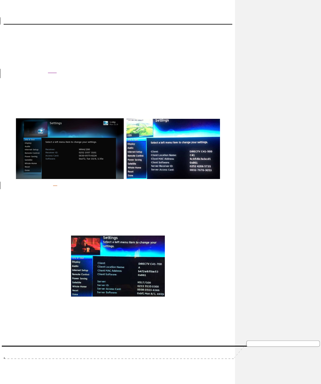
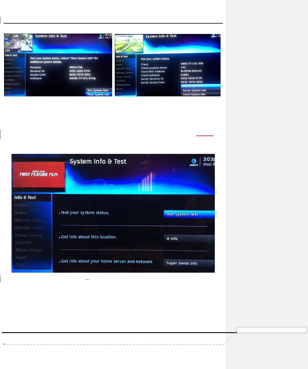
1. Settings & Help -> Settings -> Info & Test Screen Differences
Menu -> Settings & Help -> Settings -> Info & Test screens will change and have some
differences from present Genie and Clients.
These are the Info & Test screen on the Genie and Client connected to a Genie today:
Product Manual – Genie Air
TM
Version 1.3.0 – 11/22/2016
Page 32 DIRECTV, Inc. Proprietary and Confidential
功
功功
功能變
能變能變
能變數代
數代數代
數代碼變
碼變碼變
碼變更
更更
更
FIGURE 28: GENIE & CLIENTS CONNECTED TO GENIE - INFO & TEST SCREEN
This is the Setting screen on a Client connected to an Genie Air
TM
:
• Genie Air
TM
client will display the Run System Test, <Client Location
Name> Info and Super Genie Info.
• Run System Test is used to run system test on the Genie Air
TM
server.
• <Client Location Name> Info will display details about the specific client. It
is the same as the present Client System Info screen.
FIGURE 29: GENIE AIRTM INFO & TEST SCREEN
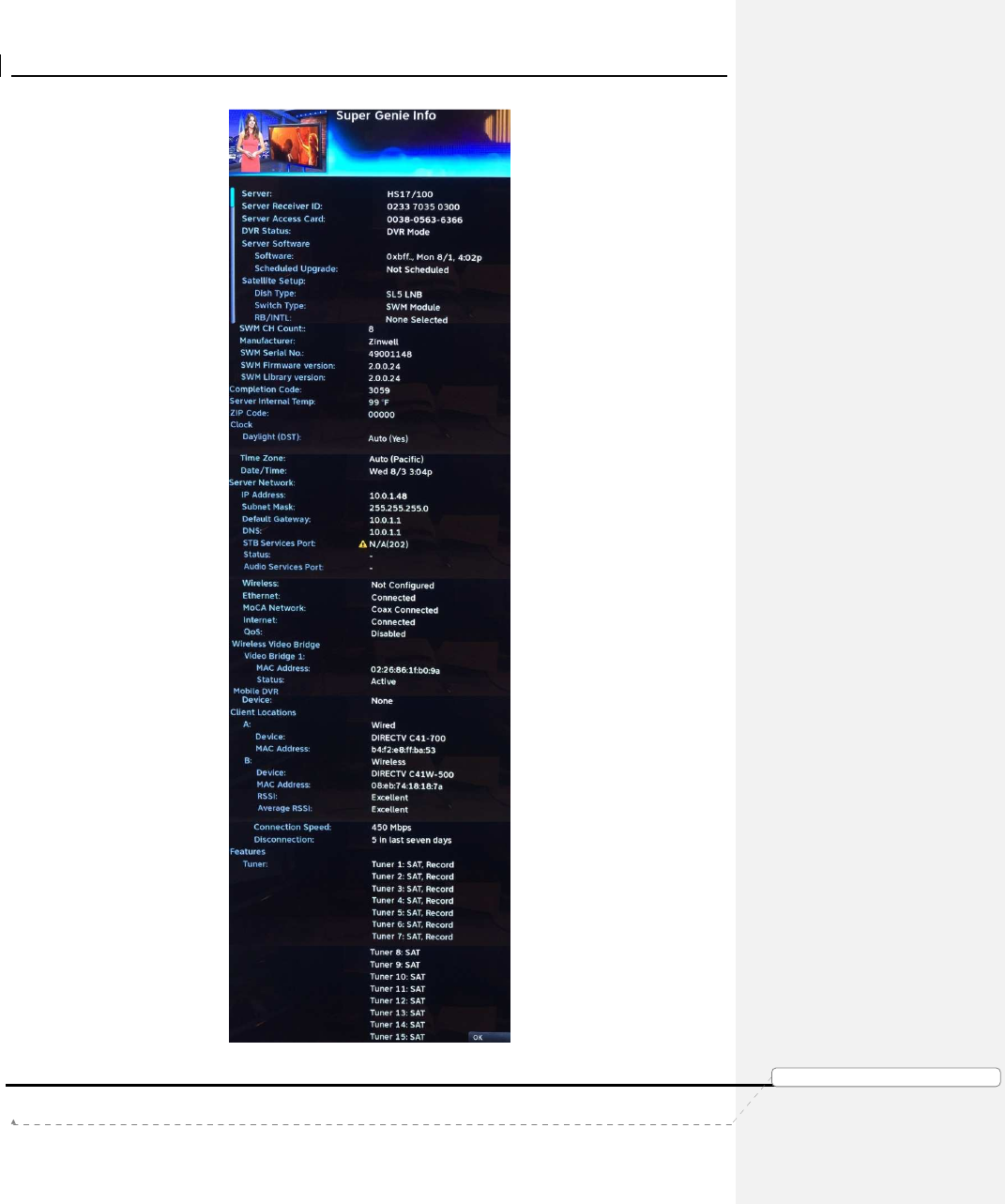
• Selecting the Super Genie Info option will display all server information. It
will NOT display any details regarding Display, Audio, Remote Control,
Captioning, HDTV, Favorites, Parental Controls and Caller ID. These
details are maintained only at specific client locations.
Product Manual – Genie Air
TM
Version 1.3.0 – 11/22/2016
Page 33 DIRECTV, Inc. Proprietary and Confidential
功
功功
功能變
能變能變
能變數代
數代數代
數代碼變
碼變碼變
碼變更
更更
更
FIGURE 30: GENIE AIRTM INFO SCREEN
Product Manual – Genie Air
TM
Version 1.3.0 – 11/22/2016
Page 34 DIRECTV, Inc. Proprietary and Confidential
功
功功
功能變
能變能變
能變數代
數代數代
數代碼變
碼變碼變
碼變更
更更
更
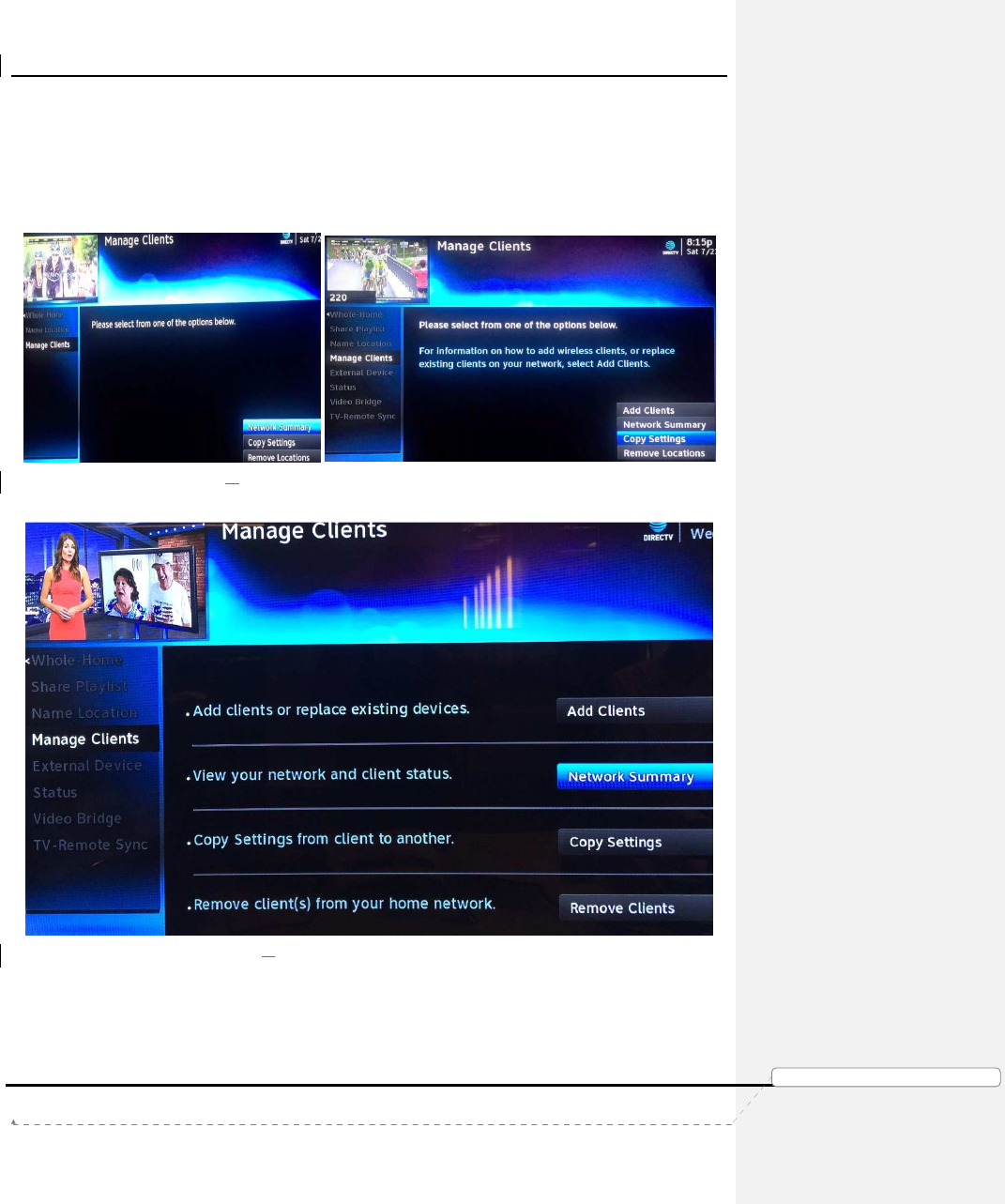
2. Settings & Help -> Settings -> Whole-Home Screen Differences
Menu -> Settings & Help -> Settings -> Whole-Home -> Manage Clients screens will
have some differences from present Genie and Clients.
These are the Manage Client screens on the Genie and Client connected to a Genie
today:
FIGURE 31: MANAGE CLIENTS - GENIE CLIENT & GENIE SERVER
This is the Manage Client screen on a Client connected to an Genie Air
TM
:
FIGURE 32: GENIE AIRTM MANAGE CLIENTS SCREEN
Product Manual – Genie Air
TM
Version 1.3.0 – 11/22/2016
Page 35 DIRECTV, Inc. Proprietary and Confidential
功
功功
功能變
能變能變
能變數代
數代數代
數代碼變
碼變碼變
碼變更
更更
更
The following are the differences in Manage Clients for a Client connect to a Genie
server versus a Client Connected to an Genie Air
TM
.
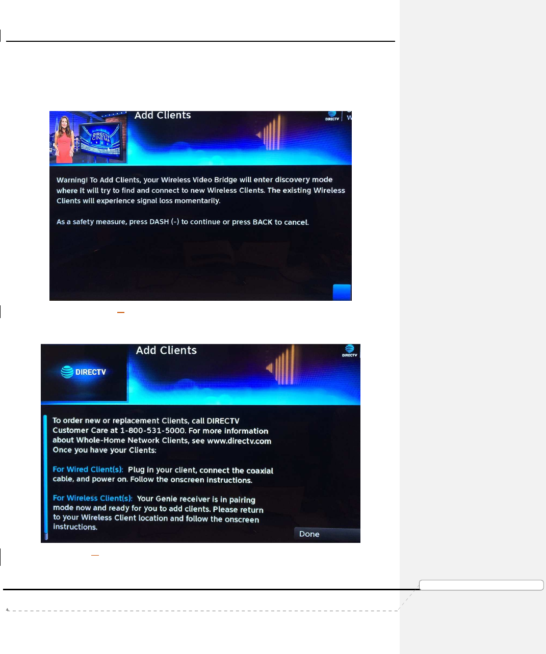
1) When the user selects the “Add Clients” button, the following screen is
displayed.
FIGURE 33: GENIE AIRTM MANAGE CLIENTS - ADD CLIENTS SCREEN
2) When the user presses the “Dash” key the following screen is displayed with on-
screen instructions to Add the client.
FIGURE 34: GENIE AIRTM MANAGE CLIENTS - ADD CLIENTS INSTRUCTIONS SCREEN
Product Manual – Genie Air
TM
Version 1.3.0 – 11/22/2016
Page 36 DIRECTV, Inc. Proprietary and Confidential
功
功功
功能變
能變能變
能變數代
數代數代
數代碼變
碼變碼變
碼變更
更更
更
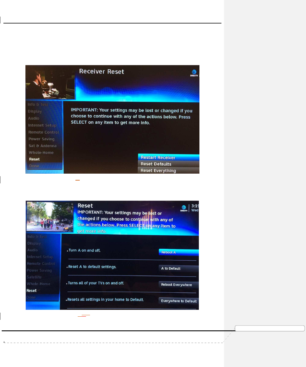
3. Settings & Help -> Settings -> Reset Screen Differences
Menu -> Settings & Help -> Settings -> Reset screen will have some differences from
present Genie and Clients.
This is the Reset screen on the Genie and Client connected to a Genie today:
FIGURE 35: RECEIVER RESET - GENIE CLIENT & SERVER
This is the Reset screen on a Client connected to an Genie Air
TM
:
FIGURE 363634: GENIE AIRTM - RESET CLIENT SCREEN
Product Manual – Genie Air
TM
Version 1.3.0 – 11/22/2016
Page 37 DIRECTV, Inc. Proprietary and Confidential
功
功功
功能變
能變能變
能變數代
數代數代
數代碼變
碼變碼變
碼變更
更更
更
When the user selects “Reboot <Client Location Name>”, the following confirmation
screen is displayed and when the user presses the Dash key, the client will reboot.
FIGURE 37: GENIE AIRTM - RESET CLIENT CONFIRMATION SCREEN
When the user selects “Reboot <Client Location Name> to Default”, a confirmation
screen is displayed and when the user press the Dash key, the specific client will reset
to defaults.
FIGURE 38: GENIE AIRTM - RESET CLIENT TO DEFAULT SCREEN
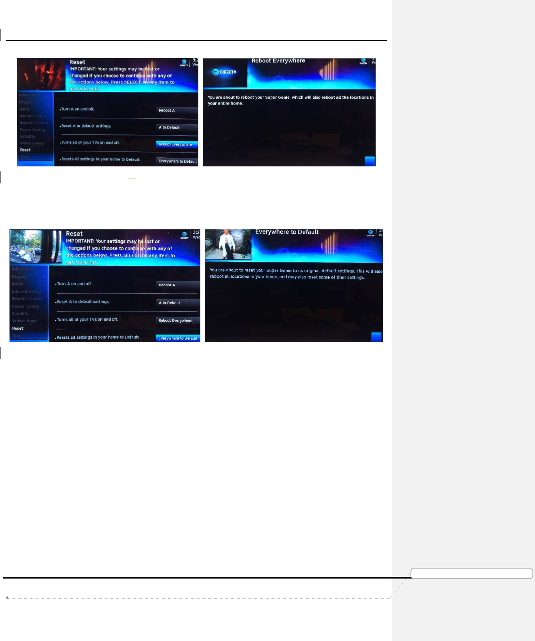
When the user selects “Reboot Everywhere”, the following confirmation screen is
displayed and when the user presses the Dash key, all the client locations will reboot.
This functionality is similar to “Reset Everything” on the Genie server and clients.
Product Manual – Genie Air
TM
Version 1.3.0 – 11/22/2016
Page 38 DIRECTV, Inc. Proprietary and Confidential
功
功功
功能變
能變能變
能變數代
數代數代
數代碼變
碼變碼變
碼變更
更更
更
FIGURE 39: GENIE AIRTM - REBOOT EVERYWHERE SCREEN
When the user selects “Everywhere to Default”, the following confirmation screen is
displayed and when the user presses the Dash key the server and all the client
locations are reset to default. This functionality is similar to the Reset Defaults on the
Genie server and clients.
FIGURE 40: GENIE AIRTM - EVERYWHERE TO DEFAULT SCREEN
4. Settings & Help -> Settings -> Remote Control Screen Differences
All the remote screens and functions are the same as when a Client is connected to a
Genie, except the texts have been modified such that the word “receiver” has been
replaced with “location”.

Product Manual – Genie Air
TM
Version 1.3.0 – 11/22/2016
Page 39 DIRECTV, Inc. Proprietary and Confidential
功
功功
功能變
能變能變
能變數代
數代數代
數代碼變
碼變碼變
碼變更
更更
更
IX. U
PDATES TO
E
XISTING
G
ENIE
OSD
S
The following OSDs have been included / updated for Genie Air
TM
. Troubleshooting remains
the same as today.
A. VIDEO BRIDGE CONNECTION FAILED OSD
Genie Text: “Unable to connect to Wireless Video Bridge. Make sure that the WVB is in Add
Client Mode and this client is within range of your video bridge signal. ”
Genie Air
TM
client Text: “Regretfully, we can’t connect your client. Make sure you are in Add
Client Mode from an existing location and the client is within range of the Super Genie’s
wireless video signal.”
B. WIRELESS CONNECTION LOST OSD
Genie Text: “The connection to your Wireless Video Bridge (WVB) has been lost. Please
make sure the WVB and Genie server are properly connected and that they have not been
moved.”
Genie Air
TM
client Text: “Oh no! Your wireless video connection was lost.”
C. INTERNET NEVER CONNECTED, CONTENT MISSING OSD
Genie Text: “Connect your Receiver to the Internet to access DIRECTV's massive On
Demand library, including thousands of free & premium shows and movies! Select Learn
More for details.”
Genie Air
TM
client Text: “Connect your receiver to the Internet and get access to DIRECTV’s
huge On Demand library of free & paid movies and shows! Select Learn More for details”
D. PROGRAM REQUIRES INTERNET CONNECTION OSD
Genie Text: “Connect your Receiver to the Internet to watch this program and access
DIRECTV's huge On Demand library! Select Connect Now for details.”
Genie Air
TM
client Text: “Connect your Receiver to the Internet to watch this program and
access DIRECTV’s huge On Demand library! Select Connect Now and follow the onscreen
steps.”
E. WVB NOT FOUND OSD
If WVB is not found, this OSD is displayed at the client locations. Text remains the same as
Genie.
F. CONNECT TO THE INTERNET OSD
This OSD is displayed over Live TV to encourage users to connect to the internet both in
Never Connected and Previously Connected state. Text remains the same as Genie.
Product Manual – Genie Air
TM
Version 1.3.0 – 11/22/2016
Page 40 DIRECTV, Inc. Proprietary and Confidential
功
功功
功能變
能變能變
能變數代
數代數代
數代碼變
碼變碼變
碼變更
更更
更
X. F
EATURE
D
IFFERENCES
A. TRANSCODING
Genie Air
TM
has Two Built-In Transcoders. It supports Transcoding of One SD stream (at-
launch). Transcoding of HD / 4K streams will be supported in future.
B. RECORDING & STREAMING CONFLICTS
In the current Genie products, when a user exceeds streaming limits, a Streaming Conflict
OSD is displayed, and when a user tries to record on too many tuners, a Recording Conflict
warning is displayed. On a Client connected to an Genie Air
TM
, these two limitations will be
combined into one screen.
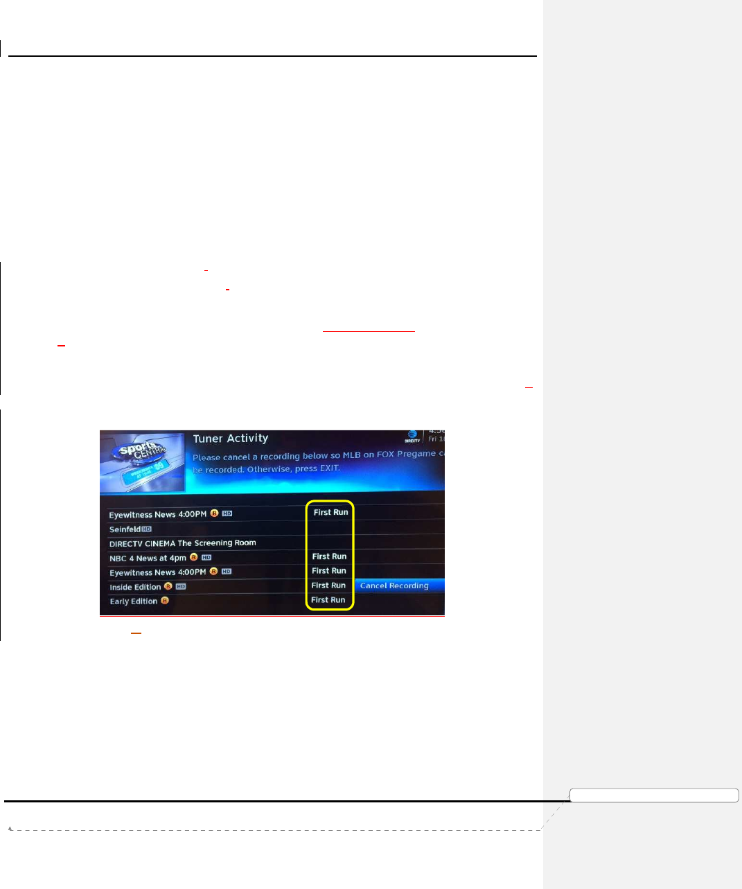
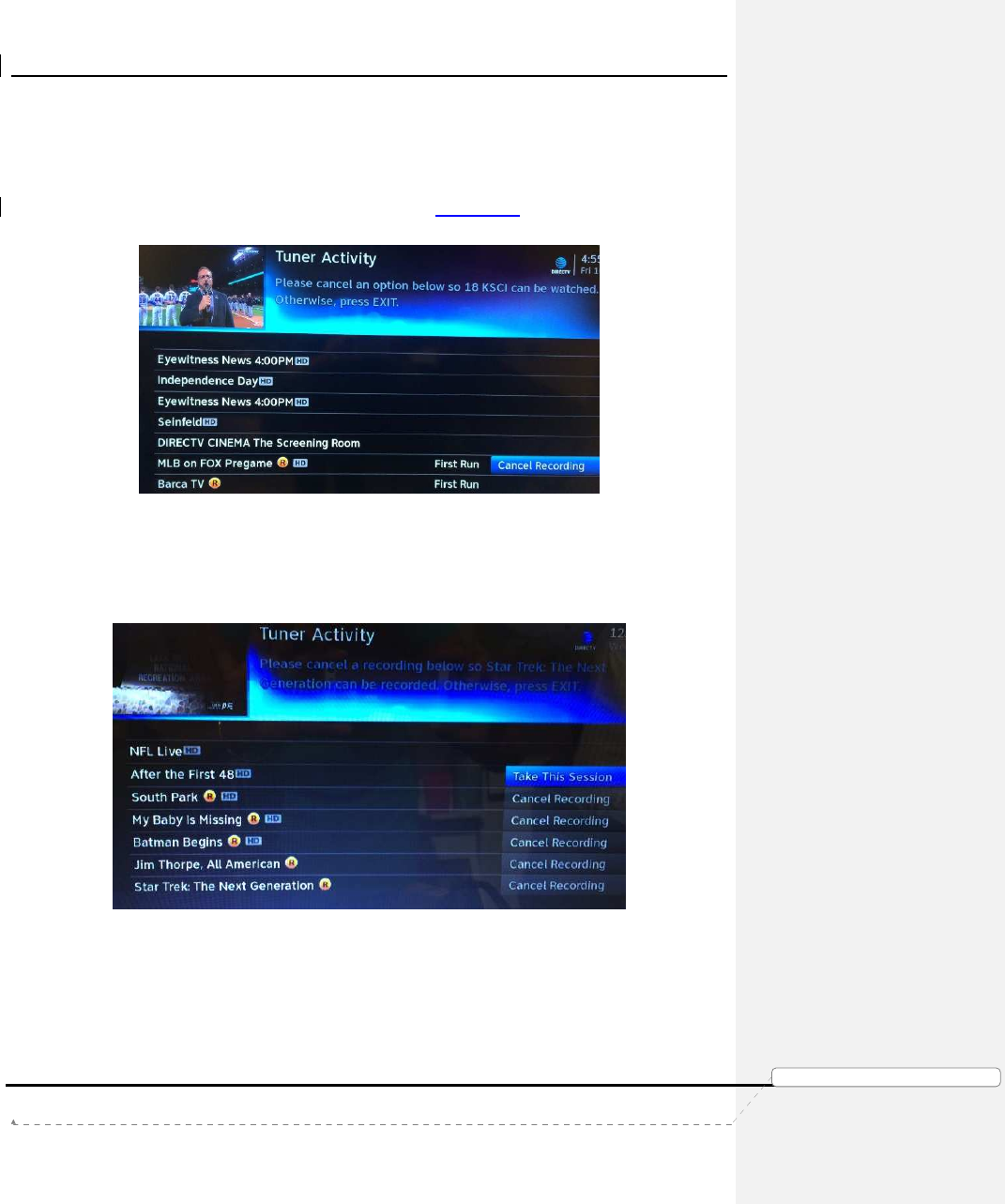
When the user tries to watch or / record an eighth program, a conflict occurs, the following
Resource Conflict OSD is displayed.
Draft Text:
“Please cancel a recording below so <New Conflict> can be recorded. Otherwise press
EXIT.”
(Or)
“Please cancel an option below so <New Conflict> can be watched. Otherwise press EXIT.”
To help provide users with better information to choose their cancellation, a new tag (First
Run) has been added to indicate First Running of a particular program.
FIGURE 41: RESOURCE CONFLICT - FIRST RUN SCREEN (SUBJECT TO CHANGE)
Each title listed corresponds to a streaming session on a client, a recording and/or a
Double-Play occurrence. The user will have the following options to resolve the conflict.
• “Cancel Recording”
• This will cancel the recoding so the tuner can be used to record/watch
another channel/title.
• No Option Available
• There will be no option if a client is currently tuned to the channel/title that
is listed, even if the title is being recorded
Product Manual – Genie Air
TM
Version 1.3.0 – 11/22/2016
Page 41 DIRECTV, Inc. Proprietary and Confidential
功
功功
功能變
能變能變
能變數代
數代數代
數代碼變
碼變碼變
碼變更
更更
更
• Clients could be either a Genie Client or a MRV Client
• If the user does not wish to cancel and there is a title with no option, they
should find the Genie Client that is watching the blocking title and put it in
Standby to release the session; or find a MRV client and stop the
playback of the recording from the Genie Air
TM
. Once this is done the
other client can start streaming a session.
FIGURE 42: RESOURCE CONFLICT - NO OPTION OR CANCEL RECORDING SCREEN
• “Take This Session”
• The “Take this session” button will be displayed if a session can be taken
during Double-Play. Selecting this will disable Double-Play at the location
the Double-Play was enabled.
FIGURE 43: RESOURCE CONFLICT DURING DOUBLE-PLAY
• Press Exit
• During conflict, if the user presses “Exit” while trying to record, the
recording will not take place. If the user presses Exit while trying to
stream a channel, it will go back to the channel the user was watching
previously before the conflict.
Product Manual – Genie Air
TM
Version 1.3.0 – 11/22/2016
Page 42 DIRECTV, Inc. Proprietary and Confidential
功
功功
功能變
能變能變
能變數代
數代數代
數代碼變
碼變碼變
碼變更
更更
更
XI. T
ROUBLESHOOTING
A. NEW OSD’S
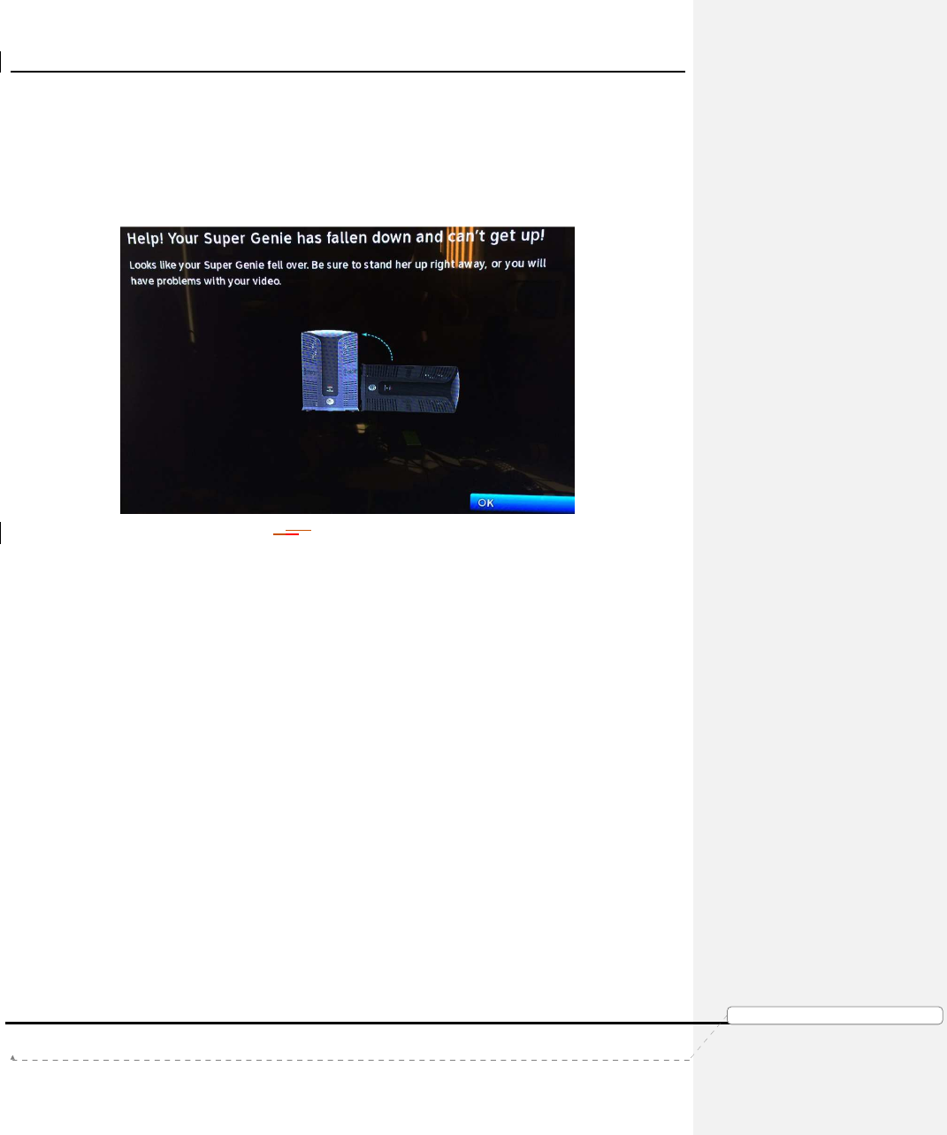
1. Tilt Error OSD
Draft Text: “Help, Your Super Genie has fallen down …”
FIGURE 444440: TILT ERROR OSD SCREEN
Cause: If the Genie Air
TM
has Tilted or fallen over this OSD will be displayed.
Troubleshooting: The user needs to set the Genie Air
TM
upright vertically. The graphic
in the OSD will inform the user the appropriate state / position the Genie Air
TM
should
be in. Set the Genie Air
TM
straight and select OK to dismiss the OSD.
2. Overheating Warning OSD
Draft Text: “Is it hot in here, or is it just me….”
Cause: If there is something blocking the Genie Air
TM
, it will restrict the airflow and
cause the Genie Air
TM
to overheat. Hence this OSD is displayed.
Troubleshooting: Check and make sure that nothing is blocking airflow to the Genie
Air
TM
. The graphic in the OSD will inform the user the state / position the Genie Air
TM
should be placed in. Select OK to restart the Genie.
3. Bad AV Chip OSD
Draft Text: “Oops, Something Went Wrong”
Cause: There is a display issue with the Genie Air
TM
which prevents it from displaying
video as soon as one client is connected to it.
Troubleshooting: Select Reboot Now to reboot the Genie Air
TM
. If problem persists, the
Genie Air
TM
needs to be replaced.

Product Manual – Genie Air
TM
Version 1.3.0 – 11/22/2016
Page 43 DIRECTV, Inc. Proprietary and Confidential
功
功功
功能變
能變能變
能變數代
數代數代
數代碼變
碼變碼變
碼變更
更更
更
B. SYSTEM TEST DIAGNOSTIC CODES
1. New Wireless IV Diagnostic Codes
TBD
2. Updates to MoCA Test Errors
All Genie MoCA test errors apply to Genie Air
TM
also. The following Error text strings
have been updated.
a. System Test Error Code 47 or 48
Genie Text: “Home Network Distribution Problem. The %s receiver has a poor
network connection. If you are having a problem viewing recordings from this
receiver, please call Customer Service at 1-800-531-5000 and report the
diagnostic code displayed above.”
Genie Air
TM
Text: “Home Network Distribution Problem. Locations below have
reduced network performance. If you are having a problem viewing recordings
from these receivers, please call Customer Service at 1-800-531-5000 and report
the diagnostic code displayed above.”
C. SYMPTOMS
1. 5GHz SSID’s not listed
Clients connected to a Genie Air
TM
will not list any 5GHz SSID’s while connecting to the
customer’s router.
Troubleshooting: Customer Education. Genie Air
TM
only uses the 2.4 GHz Wi-Fi band to
connect to the customer’s router. Hence it won’t list any 5GHz SSID’s in the network.
D. CHANGE TO EXISTING TROUBLESHOOTING ON CLIENT / SERVER
Since there is no Genie Server to help troubleshoot, there will be some changes to
troubleshooting steps. The following are changes to troubleshooting for existing client and
server scenarios.
1. Checks at Server
For all troubleshooting that has the user troubleshoot at the Genie server location,
troubleshoot as follows. The only exception is when troubleshooting “No Servers Were
Detected” and “Wireless Connection Lost”.
• If the issue occurs only on one client, troubleshoot at the specific client
using another client as a reference of the Genie server.
• If the issue occurs on all clients or there is only one client in the home,
reboot the Genie server.
2. No Servers Were Detected
Symptoms: OSD displays: “No Servers were detected, Check your network
connections”.
Cause:
• Genie Air
TM
may not be plugged in.
Product Manual – Genie Air
TM
Version 1.3.0 – 11/22/2016
Page 44 DIRECTV, Inc. Proprietary and Confidential
功
功功
功能變
能變能變
能變數代
數代數代
數代碼變
碼變碼變
碼變更
更更
更
• One of the clients may be on a screen such as:
• System Test
• Signal Strength
• Satellite Setup
• There may be a connection issue between the Genie Air
TM
and the
wired client.
• There may be a connection issue between the Genie Air
TM
and the
Wireless Video Bridge.
• The Genie Air
TM
was replaced and the Add Client steps were not
completed.
Troubleshooting:
Scenario
Genie Mini Client
Wireless Genie Mini Client
If other Clients
do not have this
OSD;
1) Check for loose connections at the
Genie Mini clients that have this OSD.
• Ensure there are no Band-Stop
Filters connected to the Genie
Mini Clients
2) Reset the Genie Mini client.
3) Reset the Genie Air
TM
.
4) Schedule service call.
1) Ensure the Network LED on the client is
Solid Green
2) If not solid green, troubleshoot Wireless
Client using existing troubleshooting
steps.
3) Reset Wireless Genie Mini client.
4) Reset the Genie Air
TM
.
5) Schedule service call.
If all Clients have
the same OSD;
Or if there are no
other Clients in
the home:
1)
Is this the first time using the Genie
Mini clients after a Genie Air
TM
server
replacement?
•
If No, continue.
•
If Yes: Follow the Add Client
process and add the Genie Mini
clients.
2)
Check if the following services are
active on the user’s account.
•
Advanced Receiver Service
•
Whole Home DVR Service
•
DVR Service
•
HD Access
3)
Go to the Genie Air
TM
and check if the
Status LED is Solid Green.
• If not solid green, troubleshoot
as per the Status LED table.
4)
Check if the MoCA LED at the back
panel of the Genie Air
TM
is Solid Green.
• If not solid green, troubleshoot
as per the MoCA LED table.
5)
If there are no other clients in the home
(Single client home), first reset the
Genie Mini client. If OSD is still present
reset the Genie Air
TM
.
6)
In case of multiple client household,
reset the Genie Air
TM
.
7)
Is the OSD still present on all clients?
• Yes: Schedule service call.
• No: Check the other Clients
and if the OSD is still present then
1)
Is this the first time using the Wireless
Genie Mini after a Genie Air
TM
server
replacement?
•
If No, continue.
•
If Yes: Reset the Wireless Connection as
with a Genie then follow the Add Client
process
2)
Check if the following services are active
on the user’s account.
•
Advanced Receiver Service
•
Whole Home DVR Service
•
DVR Service
•
HD Access
3)
Go to the Genie Air
TM
and check if the
Status LED is Solid Green.
• If not solid green, troubleshoot as
per the Status LED table.
4)
Check if the Wireless LED is Solid Green.
• If not solid green, troubleshoot as
per the Wireless LED table.
5)
If there are no other clients in the home
(Single client home), first reset the
Wireless Genie Mini client. If OSD is still
present reset the Genie Air
TM
.
6)
In case of multiple client household, reset
the Genie Air
TM
.
7)
Is the OSD still present on all clients?
• Yes: Schedule service call.
• No: Check the other Clients and if
the OSD is still present then
troubleshoot as per “Other clients do
Product Manual – Genie Air
TM
Version 1.3.0 – 11/22/2016
Page 45 DIRECTV, Inc. Proprietary and Confidential
功
功功
功能變
能變能變
能變數代
數代數代
數代碼變
碼變碼變
碼變更
更更
更
troubleshoot as per “Other clients do
not have this OSD” script above.
not have this OSD” script above.
3. Wireless Connection Lost
Symptoms: OSD displays: “Wireless Connection Lost. The connection to wireless
video bridge has been lost. Please make sure all wireless video bridges and
server are properly connected and that this client is within range of the wireless
video bridge”.
Cause: • The internal Wireless Video Bridge lost power or is rebooting.
• The Wireless client is not in range of the Wireless Video Bridge or
Genie Air
TM
.
• The Genie Air
TM
was replaced.
Troubleshooting:
Initial troubleshooting steps remain the same as present Wireless Genie Mini
client.
Scenario
Wireless Genie Mini Client
If other Clients do not have
this OSD;
1)
Check if the Network LED on the wireless client
is Solid Green
• If not solid green, troubleshoot using
existing troubleshooting steps for
Wireless Client LEDs.
2)
Reset Wireless Genie Mini client.
3)
At the Genie Air
TM
check if the Status LED is
Solid Green.
• If not solid green, troubleshoot as per the
Genie Air
TM
Status LED table.
4)
Check if the Wireless LED is Solid Green.
• If not solid green, troubleshoot as per the
Genie Air
TM
Wireless LED table.
5)
Reset the Genie Air
TM
.
• If the Wireless Genie Mini client still has
the OSD, schedule service call.
If all Clients have the
same
OSD;
Or if there are no other
Clients in the home:
1)
Is this the first time using the Wireless Genie
Mini after a Genie Air
TM
server replacement?
•
If No, continue.
•
If Yes: Reset the Wireless Connection as with a
Genie then follow the Add Client process
2)
Check if the following services are active on the
user’s account.
•
Advanced Receiver Service
•
Whole Home DVR Service
•
DVR Service
•
HD Access
3)
At the Genie Air
TM
check if the Status LED is
Solid Green.
• If not solid green, troubleshoot as per the
Genie Air
TM
Status LED table.
4)
Check if the Genie Air
TM
Wireless LED is Solid
Green.
•
If not solid green, troubleshoot as per the

Product Manual – Genie Air
TM
Version 1.3.0 – 11/22/2016
Page 46 DIRECTV, Inc. Proprietary and Confidential
功
功功
功能變
能變能變
能變數代
數代數代
數代碼變
碼變碼變
碼變更
更更
更
Genie Air
TM
Wireless LED table.
5)
Reset the Genie Air
TM
.
• If the Wireless Genie Mini clients still have
the OSD, schedule service call.
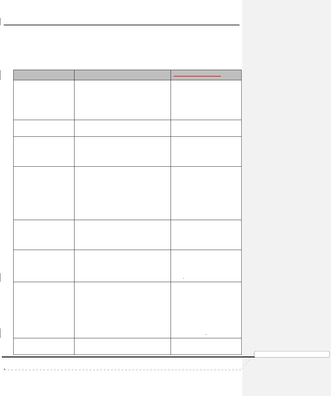
Product Manual – Genie Air
TM
Version 1.3.0 – 11/22/2016
Page 47 DIRECTV, Inc. Proprietary and Confidential
功
功功
功能變
能變能變
能變數代
數代數代
數代碼變
碼變碼變
碼變更
更更
更
XII. LED
S
UMMARY
A. FRONT PANEL LEDS
1. Status LED Table
Color
Interpretation
Troubleshooting
Off/No Color
No Power
Check if the Power LED at
the back panel is Green and
wait for 10 seconds.
If LED continues to remain
Off, reboot server.
Flashing Green
Booting (
Also IV Active, Data Feed Tests
)
N
ormal
Behavior during
boot-up
Solid
Blue
Activation / Client Add Ready
(Internal WVB has a good Connection to
the Server but No Clients paired with
Wireless Video Bridge)
Normal Behavior during
guided setup.
Solid
Yellow
Dish Not Detected (
or
) IV / Data Feed
Failed
This state occurs during
guided setup.
Check the Mobile
Installation App or RVU
client to see the error screen
and troubleshoot
accordingly.
Solid Green System Ready / Config Complete
(Wireless Clients should have a
connection to the server)
(normal operating color)
Normal Behavior on boot-up
complete. (Normal operating
state).
Solid Red
System Error
Restart the
Genie Air
TM
.
If LED continues to display
Solid Red, replace the Genie
Air
TM
.
Flashing Red
System
Error, trying to self
-
repair
Wait for TBD minutes to
check if the LED changes to
another state.
Else restart the Genie Air
TM
.
If the LED continues to
display Flashing Red, replace
the Genie Air
TM
.
Flashing White
Downloading Software
Normal Behavior during
SWDL.
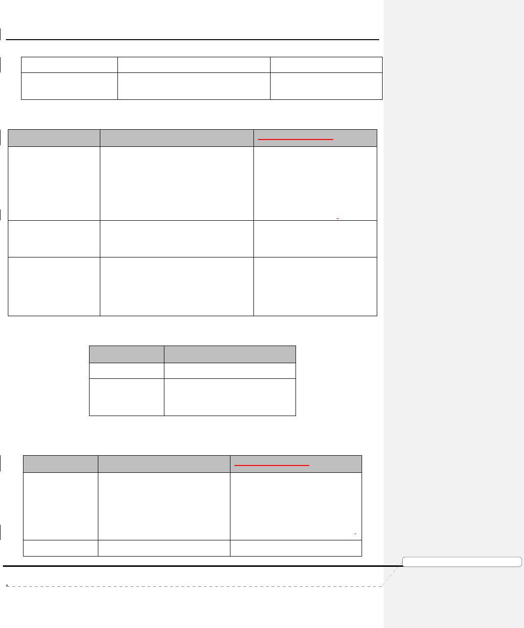
Product Manual – Genie Air
TM
Version 1.3.0 – 11/22/2016
Page 48 DIRECTV, Inc. Proprietary and Confidential
功
功功
功能變
能變能變
能變數代
數代數代
數代碼變
碼變碼變
碼變更
更更
更
Solid White
Power On, Boot
ing up
Normal Behavior during
boot-up
2. Wireless LED (Internal WVB Status)
Color
Interpretation
Troubleshooting
Off
Wireless Video Not Transmitting (
Can’t
detect WVB)
(Device Error)
Wait for TBD minutes to check if
the LED changes to another
state.
Else restart the Genie Air
TM
.
If LED continues to remain Off,
replace the Genie Air
TM
.
Solid Green Wireless Video Ready
(Wireless Clients should have a
connection to the server)
Normal operating state.
Flash Yellow Degraded Wireless Video due to Tilt
(The Wireless Video Bridge has a good
connection to the Genie server; however
there is a Poor Wireless connection to
one or more C41W clients)
Set the Genie Air
TM
is in a Vertical
upright position.
B. TOP PANEL LED – ADD CLIENT
Color
Interpretation
Off
WCA Off
Flash Green WCA Active
(WVB in Beacon Mode. Coax
Network connected)
C. B
ACK PANEL LEDS
1. Power LED
Color
Interpretation
Troubleshooting
Off/No color
Genie Air
TM
has no power Connect the power cord and
ensure there is Power at the
outlet.
If no Power replace Power Supply.
If issue persists replace Genie Air
TM
.
Green Genie Air
TM
has power Normal operating state.
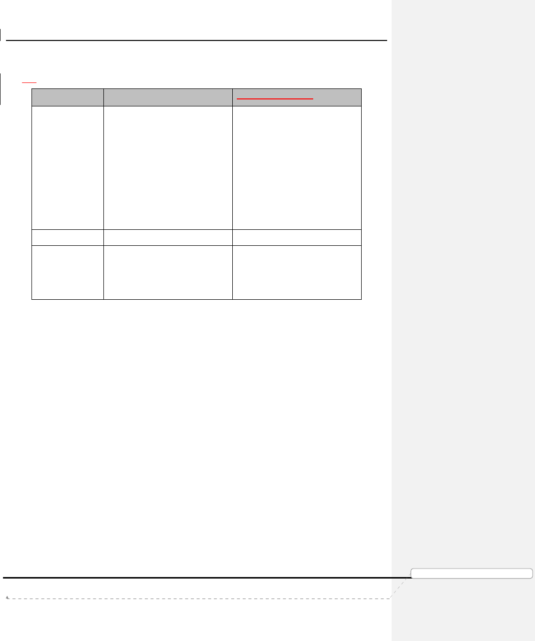
Product Manual – Genie Air
TM
Version 1.3.0 – 11/22/2016
Page 49 DIRECTV, Inc. Proprietary and Confidential
功
功功
功能變
能變能變
能變數代
數代數代
數代碼變
碼變碼變
碼變更
更更
更
2. MoCA LED
Color
Interpretation
Troubleshooting
Off/no color
No link
When there is a wired client or
external WVB in the network,
the MoCA LED will turn On or
change states. It will remain Off
when there are Only wireless
clients in the network.
In case of wired clients, check
connections at all wired
locations.
If issue persists, reboot server.
Solid Green Good MoCA link Normal operating state.
Solid Yellow
Poor
MoCA
link
Check connections at all wired
locations.
If issue persists, schedule service
call.
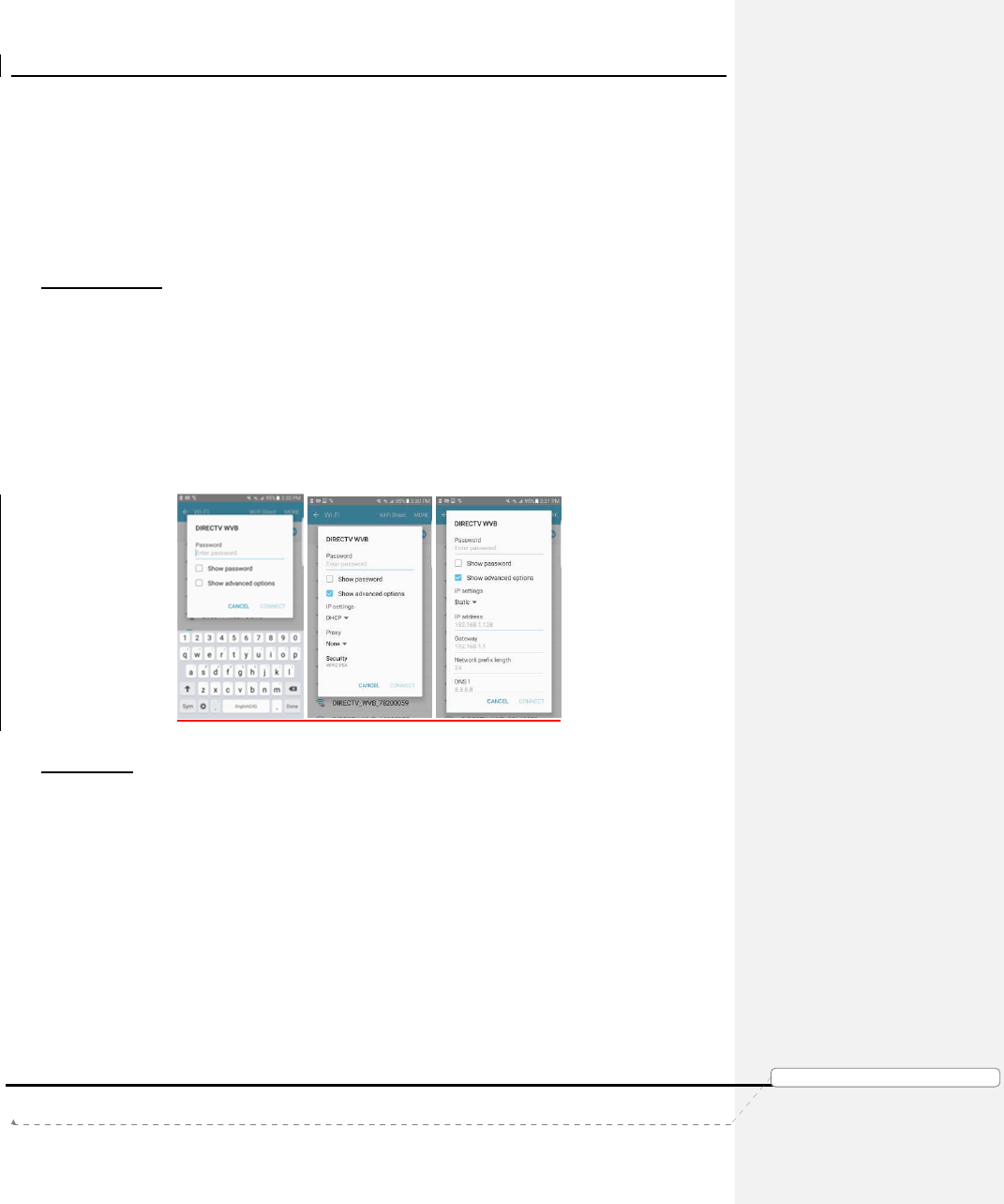
Product Manual – Genie Air
TM
Version 1.3.0 – 11/22/2016
Page 50
DIRECTV, Inc. Proprietary and Confidential
功
功功
功能變
能變能變
能變數代
數代數代
數代碼變
碼變碼變
碼變更
更更
更
XIII. A
PPENDIX
A. S
TEPS
T
O
C
ONNECT
M
OBILE
I
NSTALLATION
A
PP TO THE
WVB:
Follow the below steps to configure the Installer’s mobile device so that it can connect to the
WVB. The Mobile Installation App is a One-time setup. Once these steps are completed the
Installer’s mobile device should automatically connect to any WVB and Genie Air
TM
that is in
Add Client mode.
Android Devices
1. Enter Wi-Fi settings on the Android Device.
2. Find and select network titled DIRECTV WVB
3. Enter password S!te $urvey Mod3 0nly
4. Select “Show advanced options”
5. Under IP settings, change setting from DHCP to Static
6. Manually enter IP address below as 169.254.9.99 (double check that Gateway address
below automatically updates to 169.254.9)
7. Change Network prefix length to 16
8. Select Connect
FIGURE 45: ANDROID SETTINGS SCREEN
iOS Devices
1. Enter Wi-Fi settings on the iOS device.
2. Find network titled DIRECTV WVB and select the info button
3. Under IP Address, change setting from DHCP to Static
4. Manually enter IP address below as 169.254.9.99
5. Select Join Network
6. Enter password S!te $urvey Mod3 0nly
7. Select Subnet Mask
8. Enter 255.255.0.0
9. Select Join
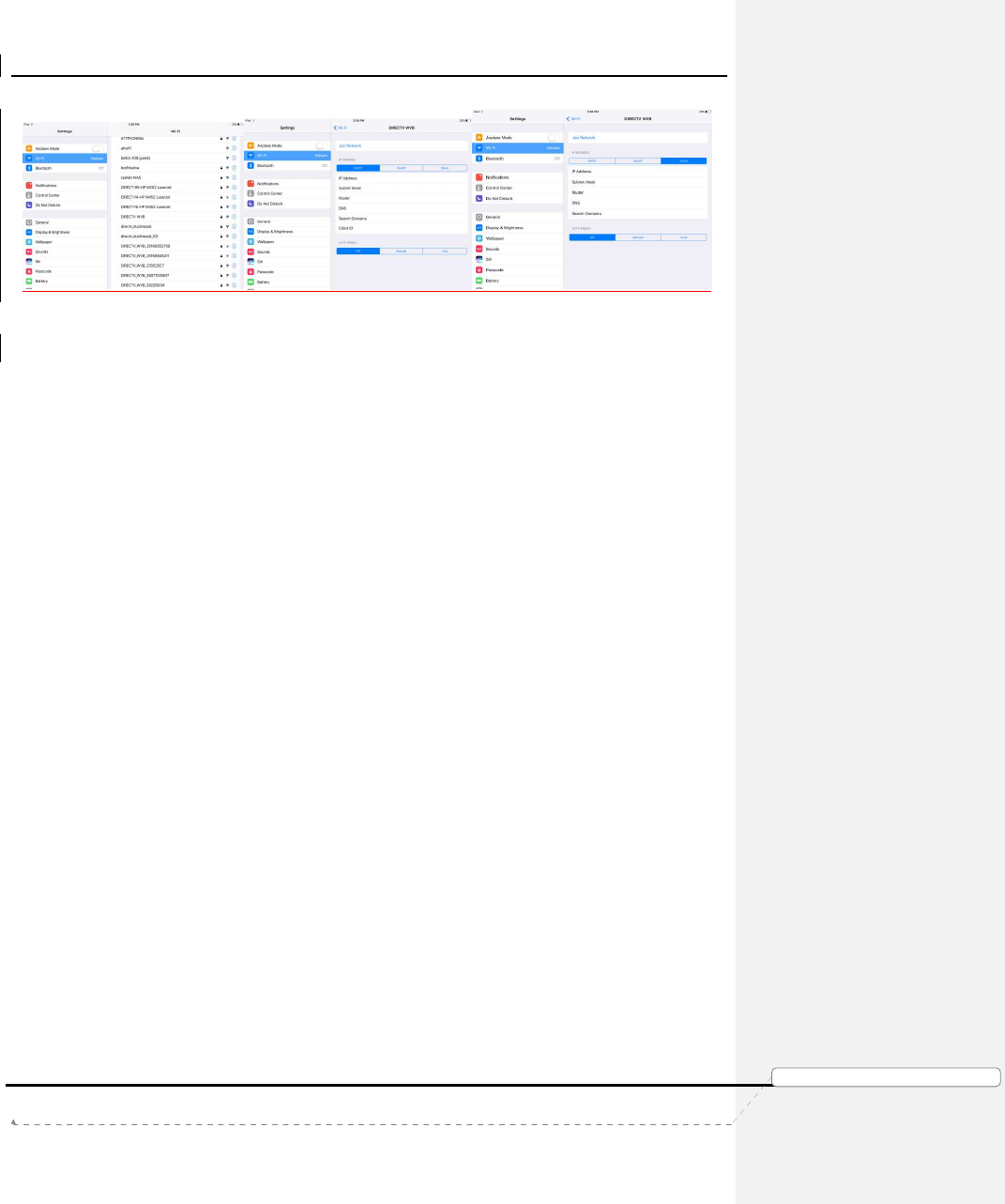
Product Manual – Genie Air
TM
Version 1.3.0 – 11/22/2016
Page 51 DIRECTV, Inc. Proprietary and Confidential
功
功功
功能變
能變能變
能變數代
數代數代
數代碼變
碼變碼變
碼變更
更更
更
FIGURE 46: IOS SETTINGS SCREEN
B. FEDERAL COMMUNICATIONS COMMISSION INTERFERENCE STATEMENT
Federal Communication Commission Interference Statement
This equipment has been tested and found to comply with the limits for a Class B digital device,
pursuant to Part 15 of the FCC Rules. These limits are designed to provide reasonable
protection against harmful interference in a residential installation. This equipment generates,
uses and can radiate radio frequency energy and, if not installed and used in accordance with
the instructions, may cause harmful interference to radio communications. However, there is no
guarantee that interference will not occur in a particular installation. If this equipment does
cause harmful interference to radio or television reception, which can be determined by turning
the equipment off and on, the user is encouraged to try to correct the interference by one of the
following measures:
●
Reorient or relocate the receiving antenna.
●
Increase the separation between the equipment and receiver.
●
Connect the equipment into an outlet on a circuit different from that to which the receiver is
connected.
●
Consult the dealer or an experienced radio/TV technician for help.
FCC Caution: Any changes or modifications not expressly approved by the party responsible for
compliance could void the user’s authority to operate this equipment.
This device complies with Part 15 of the FCC Rules. Operation is subject to the
following two conditions: (1) This device may not cause harmful interference, and
(2) this device must accept any interference received, including interference that
may cause undesired operation.
This device is restricted for indoor use.
Product Manual – Genie Air
TM
Version 1.3.0 – 11/22/2016
Page 52 DIRECTV, Inc. Proprietary and Confidential
功
功功
功能變
能變能變
能變數代
數代數代
數代碼變
碼變碼變
碼變更
更更
更
IMPORTANT NOTE:
FCC Radiation Exposure Statement:
This equipment complies with FCC radiation exposure limits set forth for an uncontrolled
environment. This equipment should be installed and operated with minimum distance 20cm
between the radiator & your body.
FCC
警語
.doc
FE
TC_D-088_HR34-44_Goliath-Flower SWDL 3.2.0 13 1219 ABRIDGED.docx
功
功功
功能變
能變能變
能變數代
數代數代
數代碼變
碼變碼變
碼變更
更更
更
功
功功
功能變
能變能變
能變數代
數代數代
數代碼變
碼變碼變
碼變更
更更
更