Hypermedia Systems 3-4-7-K Cellular Gateway User Manual HG4000 Admin Guide PR
Hypermedia Systems Ltd. Cellular Gateway HG4000 Admin Guide PR
Contents
- 1. User manual I
- 2. User manual II
User manual I
Hypermedia Gateways
HG-4000 3U and 6U
Product Manual
6U
3U

HMC Product Manual
Release 3.4: May 2010
Contact Information
2b, Professor Bergman St.,
Rabbin Science Park,
Rechovot, 76100,
Israel
Phone: +972-8-936-3077
Fax: +972-8-936-3066
For general inquiries: info@hyperms.com
For sales inquiries: sales@hyperms.com
For Technical Support: support@hyperms.com
Web site: http://www.hyperms.com/
Document Information
© May 2010 Hypermedia Systems, Ltd. All rights reserved.
No part of this document may be reproduced or transmitted in any form or
by any means, electronic or mechanical, for any purpose, without the
express written permission of Hypermedia, Inc. Under the law, repro-
ducing includes translating into another language or format.
Every effort has been made to ensure that the information in this manual
is accurate. Hypermedia, Inc. is not responsible for printing or clerical
errors. Information in this document is subject to change without notice.
Trademarks and Software Information
Hypermedia ® and the Hypermedia logo design are registered trade-
marks of Hypermedia, Inc. in the United States and various other coun-
tries. All other trademarks are the property of their respective owners.
Software Protection
As between the parties, Hypermedia Systems, Ltd. retains title to, and
ownership of, all proprietary rights with respect to the software contained
within its products. The software is protected by United States copyright
laws and international treaty provision. Therefore, you must treat the soft-
ware like any other copyrighted material (e.g. a book or sound recording).

HMC Product Manual
Release 3.4: May 2010
Hypermedia Systems Ltd. LICENSE AGREEMENT AND WARRANTY
IMPORTANT — READ CAREFULLY
This Hypermedia Systems Ltd. License Agreement (the "AGREEMENT") is a legal agreement between you (either
an individual or a single entity) and Hypermedia Systems Ltd. for the product accompanying this AGREEMENT.
The product includes computer software, associated media and printed materials, and may include "online" or elec-
tronic documentation (the "SOFTWARE"). The PRODUCT may also include hardware (the “HARDWARE”). The
SOFTWARE and the HARDWARE are referred to, collectively, as the PRODUCT.
BY INSTALLING AND/OR USING THE PRODUCT YOU AGREE TO BE BOUND BY THE TERMS OF THIS
AGREEMENT.
IF YOU DO NOT AGREE TO THE TERMS OF THIS AGREEMENT, PROMPTLY ERASE ALL COPIES OF THE
SOFTWARE IN YOUR POSSESSION, AND RETURN THE SOFTWARE AND ANY ACCOMPANYING HARD-
WARE TO THE PLACE FROM WHICH YOU OBTAINED IT.
COPYRIGHT.
All title and copyrights in and to the PRODUCT are owned by Hypermedia Systems Ltd. The PRODUCT is pro-
tected by copyright laws and international copyright treaties, as well as other intellectual property laws and treaties.
GRANT OF LICENSE FOR THE SOFTWARE.
The SOFTWARE is licensed, not sold. Hypermedia Systems Ltd. grants to you a non-exclusive, non-transferable,
royalty-free right to install and use the SOFTWARE, provided that the SOFTWARE will be used by a single person
on a single computer and for personal non-commercial, internal use only. If accompanied by a proof-of-purchase
document specifying "site license," "company license," or any other multiple-user type license scheme, then the
terms of that document shall override this single-user restriction. Any rights not expressly granted herein are
retained by Hypermedia Systems Ltd.
OTHER RESTRICTIONS.
This AGREEMENT is your proof of license to exercise the rights granted herein and must be retained by you. You
may not rent, lease, reverse engineer, decompile, modify, or disassemble the PRODUCT, or create derivative
works based on the PRODUCT.
LIMITED HARDWARE WARRANTY
The HARDWARE is protected against defects in material and workmanship, under normal use, for one (1) year
from the original purchase date.
If the HARDWARE fails to perform within the abovementioned warranty period, you must return the PRODUCT to
Hypermedia Systems Ltd. and prepay any shipping charges, export taxes, custom duties and taxes, or any
charges associated with transportation of the Product. In addition, you are responsible for insuring the PRODUCT
shipped or returned and assume the risk of loss during shipment.
All returned PRODUCTS must be accompanied by a description of the problem, a proof of the place and date of
purchase, and the original shipping and packing materials.
Hypermedia Systems Ltd. shall, at its sole discretion, either repair the PRODUCT or replace it with a product of the
same functionally. Replacement products may be refurbished or contain refurbished materials. If Hypermedia Sys-
tems Ltd. cannot repair or replace the PRODUCT, Hypermedia Systems Ltd. will refund the depreciated purchase
price of the PRODUCT.
This limited warranty does not apply to any PRODUCT not purchased from Hypermedia Systems Ltd., or from a
Hypermedia Systems Ltd. authorized reseller, or on which the serial number has been removed or defaced. This
limited warranty also does not cover any PRODUCT that has been damaged or rendered defective as a result of
(a) improper transportation or packing when returning the PRODUCT to Hypermedia Systems Ltd.; (b) use of the
PRODUCT other than in accordance with its instructions, or other misuse or abuse of the PRODUCT; (c) modifica-
tion of the PRODUCT; (d) service by anyone other than a Hypermedia Systems Ltd.-approved agent; (e) unusual
physical or electrical stress or interference, failure or fluctuation of electrical power, lightning, static electricity,
improper temperature or humidity, fire, or acts of God.

HMC Product Manual
Release 3.4: May 2010
The maximum liability of Hypermedia Systems Ltd. under this limited warranty is limited to the purchase price of the
PRODUCT covered by the warranty.
Hypermedia Systems Ltd. reserves the right to refuse PRODUCTS (i) that are not covered by the warranty; or (ii)
for which there is no problem found. Such PRODUCTS shall be returned to the purchaser at purchaser’s expense.
DISCLAIMER.
EXCEPT AS EXPRESSLY STATED ABOVE OR AS REQUIRED BY LAW, Hypermedia Systems Ltd. DISCLAIMS
ANY WARRANTY FOR THE PRODUCT. THE PRODUCT IS PROVIDED "AS IS" WITHOUT REPRESENTATION
OR WARRANTY OF ANY KIND, EITHER EXPRESS OR IMPLIED, INCLUDING, WITHOUT LIMITATION, THE
IMPLIED WARRANTIES OF MERCHANTABILITY, FITNESS FOR A PARTICULAR PURPOSE, OR NON-
INFRINGEMENT. Hypermedia Systems Ltd. ASSUMES NO RISK ARISING OUT OF THE USE OR PERFOR-
MANCE OF THE PRODUCT.
NO LIABILITY FOR CONSEQUENTIAL DAMAGES.
IN NO EVENT SHALL Hypermedia Systems Ltd., ITS AGENTS OR ITS SUPPLIERS BE LIABLE FOR ANY DAM-
AGES WHATSOEVER (INCLUDING, WITHOUT LIMITATION, DIRECT, INDIRECT, SPECIAL OR OTHER CON-
SEQUENTIAL OR INCIDENTAL DAMAGES; DAMAGES FOR LOSS OF BUSINESS PROFITS, BUSINESS
INTERRUPTION, LOSS OF BUSINESS INFORMATION, OR ANY OTHER PECUNIARY LOSS) ARISING
DIRECTLY OR INDIRECTLY OUT OF THE USE OF OR INABILITY TO USE THE PRODUCT, EVEN IF Hyper-
media Systems Ltd. HAS BEEN ADVISED IN ADVANCE OF THE POSSIBILITY OF SUCH DAMAGES.
Because some states or jurisdictions do not allow the exclusion or limitation of liability for consequential or inci-
dental damages, the above limitation may not apply to you.
U.S. GOVERNMENT RESTRICTED RIGHTS.
For purchases made in the United States: The SOFTWARE and any accompanying documentation are provided
with restricted rights. Use, duplication or disclosure by the Government is subject to restrictions as set forth in sub-
paragraph (b) (3) and (c) (1) (ii) of The Rights in Technical Data and Computer Software clause at DFARS
252.227-7013 or subparagraphs (c) (1) and (2) of the Commercial Computer Software-Restricted Rights at 48 CFR
52.227-19, as applicable.
AMENDMENTS.
Hypermedia Systems Ltd. may amend these terms and conditions at any time by posting a notice on one or more
of its websites. Your continued use of the PRODUCT shall constitute your acceptance of such amended terms.
Accordingly, we urge you to visit our websites periodically to review the current and effective terms and conditions
for use of our products. Certain provisions of these terms and conditions may be superceded by expressly desig-
nated legal notices or terms outlined on our websites.
GOVERNING LAW.
This AGREEMENT and any and all claims relating to the PRODUCT shall be governed by the laws of the State of
Israel, without regard to or application of choice of law or principles, and the courts of Tel-Aviv Jaffa shall have sole
and exclusive jurisdiction over any dispute arising in connection with this Agreement and/or the use of the
PRODUCT.
NO WAIVER.
No delay or failure to take action under these terms and conditions will constitute a waiver by Hypermedia Systems
Ltd. unless expressly waived in writing by a duly authorized officer of Hypermedia Systems Ltd.

HMC Product Manual i
Release 3.4: May 2010
Table of Contents
Hardware and Installation............................................................................ 1
Overview ............................................................................................................................... 2
Contents of Package ...................................................................................................... 2
Safety Information................................................................................................................. 3
System Components.............................................................................................................. 4
Installation............................................................................................................................. 7
Pre-Installation Preparation ........................................................................................... 7
Installing the D-Link DIR100 Router............................................................................ 8
Installing the RO 1.1 Embedded Router Card ............................................................. 10
Installing the Media Gateway (MG) Card ................................................................... 11
Installing the Cellular Card.......................................................................................... 12
Powering Up and LEDs....................................................................................................... 14
LEDs.................................................................................................................................... 15
HMC Quick Start ........................................................................................ 17
Installation........................................................................................................................... 18
Start-up and Initial Connection ........................................................................................... 20
User Interface Overview ..................................................................................................... 23
HMC Navigation ................................................................................................................. 24
Save/Load Configuration .................................................................................................... 26
Call Parameters ................................................................................................................... 27

HMC Product Manual ii
Release 3.4: May 2010
Configuring a Cellular Card ...................................................................... 29
Cellular Card and System Terminology.............................................................................. 30
Volume Settings .................................................................................................................. 31
Media Connections.............................................................................................................. 32
Associating/Linking Cellular Channels....................................................................... 32
Unlinking Cellular Allocations.................................................................................... 33
Callbacks ............................................................................................................................. 34
Resources..................................................................................................................... 34
Call Triggers ................................................................................................................ 35
SMS Triggers............................................................................................................... 35
Callthroughs ........................................................................................................................ 37
Dial Filters........................................................................................................................... 39
PIN Codes ........................................................................................................................... 40
MSN Values ........................................................................................................................ 41
Reset .................................................................................................................................... 42
Information Screens ............................................................................................................ 43
Module Info ................................................................................................................. 43
Serial Numbers ............................................................................................................ 43
Locks ................................................................................................................................... 44
SIM Select ........................................................................................................................... 45
SIM Counters ...................................................................................................................... 46
SIM Auto Manage............................................................................................................... 47
Call Counter Steps............................................................................................................... 48
CLI Blocking....................................................................................................................... 49
Call Limits........................................................................................................................... 50
Cell Selection ...................................................................................................................... 51
USSD SIM Balance............................................................................................................. 53
Settings ................................................................................................................................ 54
Monitoring Cellular Cards .................................................................................................. 55
All Cells....................................................................................................................... 55

HMC Product Manual iii
Release 3.4: May 2010
Reception ..................................................................................................................... 56
Status............................................................................................................................ 57
Configuring LCR......................................................................................... 59
Overview ............................................................................................................................. 60
Linking to LCR ................................................................................................................... 61
Linking from a Media Branch ..................................................................................... 61
Linking from the LCR Branch..................................................................................... 63
Editing a Target Link................................................................................................... 65
Breaking a Link (Unlink)............................................................................................. 65
Groups ................................................................................................................................. 66
Creating a Group.......................................................................................................... 66
Using the Default Group Settings................................................................................ 67
Resource Map...................................................................................................................... 68
Sample Assignment ..................................................................................................... 68
Assigning LCR Resources........................................................................................... 69
Rules.................................................................................................................................... 72
Creating a Rule ............................................................................................................ 72
Creating a Default Set of Rules ................................................................................... 74
Deleting a Rule ............................................................................................................ 74
Filters................................................................................................................................... 75
Time Frames........................................................................................................................ 76
Creating a Time Frame ................................................................................................ 76
Disabling Time Frames................................................................................................ 77
Advanced Call Routing (ACR) ........................................................................................... 78
Modifying the Existing ACR Number List ................................................................. 78
Creating a New ACR Number List File ...................................................................... 79
ACR Rules ................................................................................................................... 80
Callthrough.......................................................................................................................... 83
Number Filters..................................................................................................................... 85
Creating a Number Filter ............................................................................................. 85

HMC Product Manual iv
Release 3.4: May 2010
Applying a Callthrough Filter...................................................................................... 87
Callback Triggers ................................................................................................................ 88
CDR..................................................................................................................................... 90
Enabling Collection of CDR........................................................................................ 90
Downloading a CDR File ............................................................................................ 91
Deciphering the CDR File ........................................................................................... 91
Activating LCR in PC Cards............................................................................................... 94
LCR CDRs .......................................................................................................................... 96
Deciphering the CDR File ........................................................................................... 96
Configuring the VoIP Card ........................................................................ 99
VoIP Media Connections .................................................................................................. 100
Associating/Linking VoIP Channels ......................................................................... 100
Unlinking VoIP Allocations ...................................................................................... 102
Callthrough........................................................................................................................ 103
VoIP Settings..................................................................................................................... 105
VoIP Management Features .............................................................................................. 107
IP Filters..................................................................................................................... 107
DDI Filters (Direct Dial-in) ....................................................................................... 108
Dial Filters ................................................................................................................. 110
Call Routing............................................................................................................... 111
Phone2Net Dial Plan.................................................................................................. 111
DDI Blocking............................................................................................................. 112
Cause Codes............................................................................................................... 113
Monitoring VoIP Cards..................................................................................................... 115
Review VoIP Card Information................................................................................. 115
Controlling VoIP Line Activity ................................................................................. 116
VoIP CDRs ................................................................................................................ 117
Deciphering the VoIP CDR File................................................................................ 117

HMC Product Manual v
Release 3.4: May 2010
Managing via the HMC............................................................................. 121
User Management ............................................................................................................. 122
Add User.................................................................................................................... 122
User List..................................................................................................................... 123
VPN Groups ...................................................................................................................... 124
Number Filters................................................................................................................... 125
Scheduler........................................................................................................................... 127
Switch SIM per Slot................................................................................................... 127
Switch SIM per System ............................................................................................. 129
Reset SIM Counter .................................................................................................... 130
Set Multi SIM ............................................................................................................ 132
VoIP Channels ........................................................................................................... 133
Manual Command ..................................................................................................... 135
Callback............................................................................................................................. 137
Remote Delegation .................................................................................................... 137
Ext. Authentication .................................................................................................... 138
Callback and Callthrough......................................................................... 139
Callback Overview............................................................................................................ 140
Callback Best Practice....................................................................................................... 141
Determine a Trigger Strategy .................................................................................... 141
Allocate the Trigger Resource ................................................................................... 142
Allocate the Callback Resource................................................................................. 144
Optionally, Require PIN Code Authorization ........................................................... 146
Authorize the User..................................................................................................... 147
Inform Users .............................................................................................................. 148
Callthrough Overview ....................................................................................................... 149
Callthrough Best Practice.................................................................................................. 150
Allocate the Callthrough Resource............................................................................ 150
Determine and Configure a User Authentication Strategy ........................................ 153

HMC Product Manual vi
Release 3.4: May 2010
Inform Users .............................................................................................................. 153
CB/CT CDRs..................................................................................................................... 154
Console Suite and other Tools .................................................................. 155
Console Suite..................................................................................................................... 156
CDR Console ............................................................................................................. 156
Log Console............................................................................................................... 157
Decoding Logs........................................................................................................... 158
Service Console ......................................................................................................... 167
HGS Setup Parameters Tool ............................................................................................. 168
PRI Cause Conversion ...................................................................................................... 170
Hypermedia Gateway Server List ..................................................................................... 172
Adding a New Server................................................................................................. 172
Accessing Other Tools via the Server List ................................................................ 173
Troubleshooting ................................................................................................................ 174
Index ........................................................................................................... 177

HMC Administrator’s Guide 1 Hardware and Installation
Release 3.4: May 2010
Chapter 1
HARDWARE and INSTALLATION
Hardware and installation vary depending upon the features included with the Hypermedia
Gateway system. Skip the sections that do not apply to your system.
This section includes:
• “Contents of Package” on page 2
• “Safety Information” on page 3
• “System Components” on page 4
• “Pre-Installation Preparation” on page 7
• “Installing the D-Link DIR100 Router” on page 8
• “Installing the Media Gateway (MG) Card” on page 11
• “Installing the Cellular Card” on page 12
• “Powering Up and LEDs” on page 14
• “LEDs” on page 15

HMC Administrator’s Guide 2 Hardware and Installation
Release 3.4: May 2010 Overview
Overview
The HyperGateway family of scalable platforms empowers cost-effective corporate telephony
over fixed, cellular and IP networks. HyperGateway systems provide integrated voice commu-
nications for both on-site and remote users of small-to-large enterprises. Acting as legacy
PBX VoIP enablers, the flexible systems are easily expanded to meet evolving corporate tele-
phony needs over time.
The Hypermedia Gateway unit is a 19" x 6U or 19" x 3U rack-mountable box that connects to
the local PBX or network via a PRI card or VoIP card. It also connects to the cellular network
via up to 8 cellular cards, each card with 4 modules of cellular channels. The system enables
any combination of connectivity between its various interfaces.
Running on the HyperGateway family of platforms, HyperSaving Package is a corporate com-
munications software add-on that minimizes expenses of local, national and international calls.
The scalable system provides secure and flexible control of on-site and remote calls over fixed,
cellular and IP networks. Leveraging organizational communications resources, Web-based
management capabilities, and operators' various service tariffs, HyperSaving Package
empowers significant savings in corporate telephony expenses. HyperSaving Package
includes any combination of Corporate Call-Back, Corporate Call-Order and Corporate Call-
Through services that improve the organization's bottom line.
Contents of Package
Depending upon configuration, the package should contain some or all of the following:
• The Hypermedia Gateway unit
• PRI cables
• Ethernet cables
• 1 or 2 power cords, depending upon the configuration
• 1 to 8 indoor antennas, depending upon the configuration
• 1 control cord
• Optionally, a D-Link DIR-100 router
• The warranty certificate
• Hypermedia Software CD-ROM

HMC Administrator’s Guide 3 Hardware and Installation
Release 3.4: May 2010 Safety Information
Safety Information
Hypermedia Gateway works with a nominal mains supply voltage of 110–240V AC. Haz-
ardous voltages are present inside of this equipment. Some of the parts can also have high
operating temperatures.
To avoid injury and prevent equipment damage, observe the following safety precautions:
• Installation, service, and maintenance of the Hypermedia Gateway should be done by
qualified technicians only.
• Do not connect the Hypermedia Gateway to any power source other than the indicated
nominal source.
• The power supply cord must be connected to a socket with a valid ground. This equip-
ment should only be used in buildings with proper safety ground.
• When connecting the equipment, first, ensure that the ground connection is connected to
the rack ground or building ground.
• When disconnecting the equipment, disconnect the ground connection last.
• Opening the housing may be dangerous and invalidates the warranty. Only a qualified
technician should open the housing. Before opening, disconnect the power cable from the
equipment.
• The Hypermedia Gateway complies with all necessary safety standards. Equipment con-
nected to the Hypermedia Gateway must also comply with the applicable safety standards.
• The packaging is designed to protect against mechanical damage and should be stored.
Do not ship equipment unless it is properly packed in its original wrapping and shipping
containers.
• Make sure that the equipment top and bottom are not blocked to air movement. Leave 1U
under and on top of the equipment for proper ventilation.
• Do not operate the Hypermedia Gateway in close proximity to potentially hazardous
areas. These includes areas such as, but not exclusively, fuel stations, fuel depots, chemi-
cal works or during blasting.
• Operate the device in its normal operating position only.
• The operation of radio transmitters, which includes cellular engines, can impair the func-
tion of medical devices that have not been properly shielded. Please ask the advice of
your doctor or the manufacturer of the medical device.
• To avoid moisture condensation, allow time for the unit to adapt to the ambient tempera-
ture before switching it on.
HMC Administrator’s Guide 4 Hardware and Installation
Release 3.4: May 2010 System Components
System Components
The Hypermedia Gateway system consists of the components described below:
• The Hypermedia Gateway unit is a 19" x 6U or 19" x 3U rack-mountable box that con-
nects to the local PBX or network. The system enables any combination of connectivity
between its PRI, BRI, VoIP, and cellular interfaces.
• The unit contains a back-plan and slots for the boards described in Table 1, “Hypermedia
Gateway Boards,” on page 5. Placement of the boards varies according to product.
• The unit contains a single power supply module. A dual power supply module is also
available.
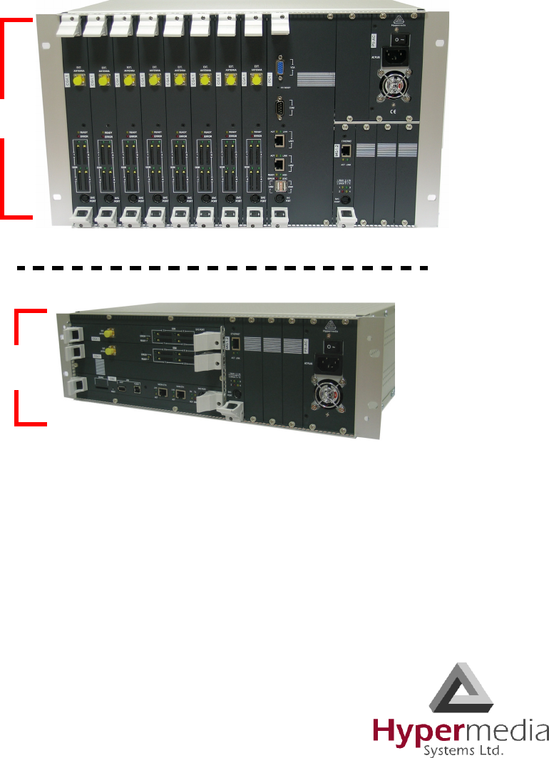
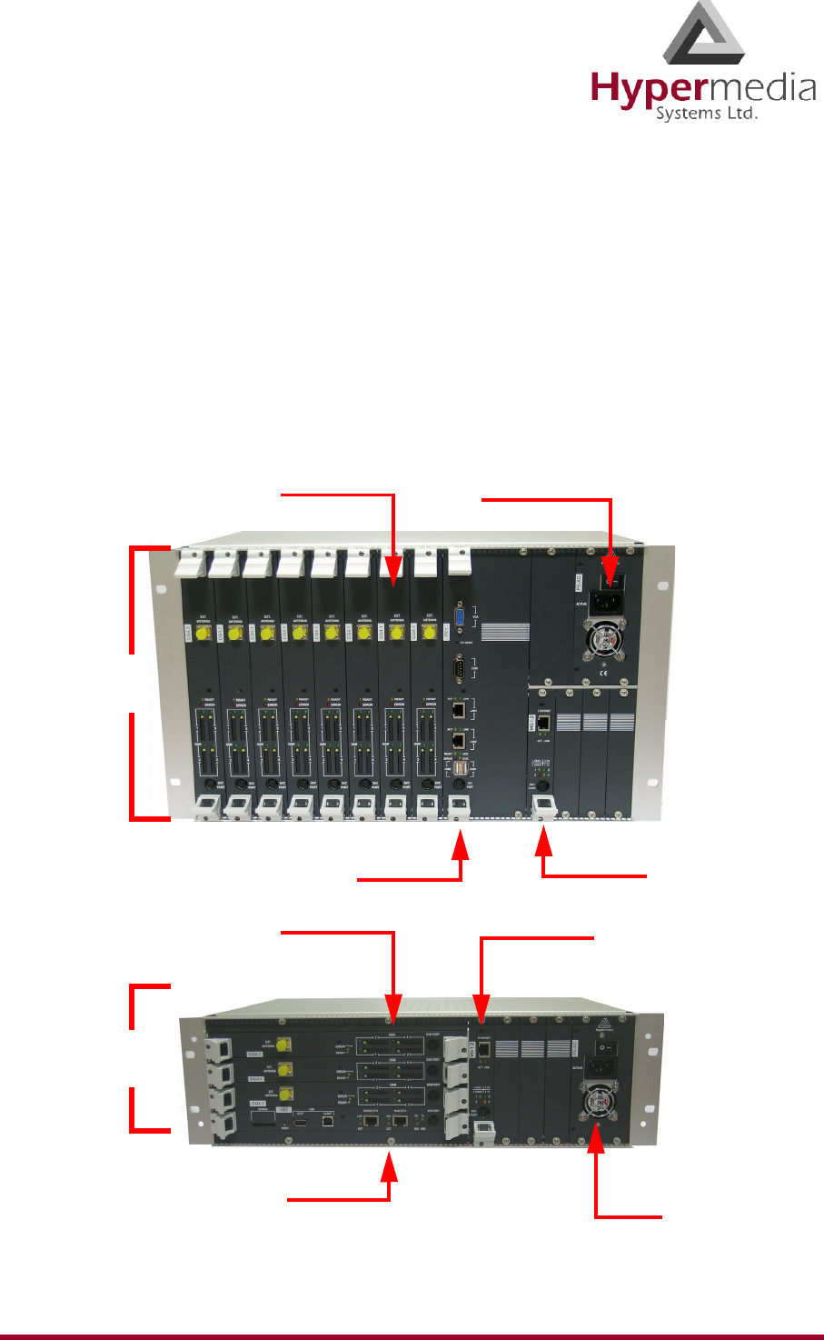
Figure 1: Examples of Boards within a Hypermedia Gateway
6U
PC Board
CG Boards Power Supply
MG Board
3U
CB Board
CG Boards MG Board
Power
Supply

HMC Administrator’s Guide 5 Hardware and Installation
Release 3.4: May 2010 System Components
• The D-LINK DIR-100 is an Ethernet Broadband Router equipped with NAT network
address translation technology. It enables the Hypermedia Gateway to connect to a public
IP and to operate behind firewalls equipped with Network Address Translation (NAT);
this provides maximum network security.
• The HyperGateway Server is an application that is embedded in the Control Board, the
PRI 2.1 board, and on the PC1/2 board. The HyperGateway Server is controlled and man-
aged by the browser-based Hypermedia Management Console.
• The Hypermedia Management Console (HMC) is used by the system administrator for
remote configuration and monitoring of the Hypermedia Gateway system. It runs over
TCP/IP and is accessed via a standard WEB browser.
Table 1: Hypermedia Gateway Boards
Board Name Description
CB1/2
Control Board
The CB1/2 module is designed for remote TCP/IP access, advanced
application and enhanced new features. It comes in two configura-
tions:
• Stand-alone embedded HyperGateway Server for some dual-
PRI configurations (single PRI with the HyperGateway Server
runs on the PRI 2.1 board mentioned below)
• VoIP Gateway add-on supporting the VoIP interface and provid-
ing a SIP/H323 interface
PC1/2
Control Board
The PC1/2 is a double-slot computer designed for use by alternative
carriers. It enables TCP/IP access and supports the VoIP Gateway.
The PC1/2 runs the HyperGateway Server for direct remote access,
and provides a SIP/H323 interface when VoIP is implemented.
CG41/CC41
Cellular Gateway
CG41 for GSM and CC41 for CDMA is a single-slot card that
enables inbound and outbound cellular voice calls for GSM and
CDMA networks.
QBRI
Quad BRI Board
The QBRI boards are single-slot cards that enable signaling over a
BRI channel on public or private ISDN. The HyperGateway Server
runs on the single QBRI board.

HMC Administrator’s Guide 6 Hardware and Installation
Release 3.4: May 2010 System Components
MG-1.1/1.2
Media Matrix and
Media Gateway
The MG-1.1/1.2- Media Matrix is a single-slot card that enables flex-
ible, pre-defined, and dynamic allocation of GSM channels, E1 PRI
B-channels, and VoIP channels.
It comes in two configurations:
• The basic Matrix slot board
• VoIP Gateway add-on supporting the VoIP interface and capable
of carrying 32–72 concurrent VoIP calls. It is designed for use
by alternative carriers.
PRI-1.1 (EOL)
and
PRI-2.1/2.2
PRI ISDN
The PRI boards are single-slot cards that enables signaling over a
Primary Rate Interface (PRI) channel on public or private Integrated
Services Digital Networks (ISDN) at E1 and T1 reference points.
The PRI-1.1 module supports a single PRI channel.
The PRI-2.x comes in two configurations:
• 2.1 single PRI with the HyperGateway Server
• 2.2 dual PRI with Bypass
RO 1.1
Router Card
The RO 1.1 module is a single-slot card that provides Ethernet
Broadband Router functionality. It is equipped with NAT network
address translation technology and enables the Hypermedia Gateway
to connect to a public IP and to operate behind firewalls equipped
with Network Address Translation (NAT)
HYD2 and HBS2
Hybrid Card
These cards combine the functionality of the MG and PRI cards.
Optionally, these cards can also support VoIP functionality. The
HYD2 supports dual PRI channels and the HBS2 supports a single
PRI channel.
Table 1: Hypermedia Gateway Boards
Board Name Description

HMC Administrator’s Guide 7 Hardware and Installation
Release 3.4: May 2010 Installation
Installation
Installation varies depending upon the boards included with the Hypermedia Gateway
system. Skip the sections that do not apply to your system.
This section is subdivided into:
• “Pre-Installation Preparation” on page 7
• “Installing the D-Link DIR100 Router” on page 8
• “Installing the Media Gateway (MG) Card” on page 11
• “Installing the Cellular Card” on page 12
• “Powering Up and LEDs” on page 14
Pre-Installation Preparation
1. Install the Hypermedia Gateway in a 19” rack. Depending upon the physical configura-
tion, the unit requires a height of either 3U or 6U. In addition, we recommend:
• Avoid installing the device near computer rooms, computer monitors, electrical
cabinets, metal objects, and windows with fold aluminum sheet.
• Perform a cellular signal check before mounting the system. This can be done by
checking the Signal Strength and the Bit Error Rate ratio on another mobile phone's
display from the same operator and system.
• Ensure that the device is protected against direct sunlight and heat. This increases
both the reliability of the operation as well as its service life.
• The antennas are for indoor use only.
• The cables to the devices should be installed so that they do not cause any physical
risk. Power cables should be installed separate from the signal cables.
2. Depending upon the configuration of your system, verify that you have some or all of the
following:
• an Ethernet or WAN socket with a fixed IP address
• a spare PRI card in your PBX
• SIM cards from your GSM operator. One SIM card is required for each GSM channel
• in case of CDMA network, a MIN or NAM from your local operator
3. To configure the Router, get the following information from your Internet Service Pro-
vider:
• WAN IP Address
• Subnet Mask, and WAN Gateway
HMC Administrator’s Guide 8 Hardware and Installation
Release 3.4: May 2010 Installation
Installing the D-Link DIR100 Router
1. Connect the D-Link DIR 100 Router to the Hypermedia Gateway. There are two ways to
connect the router depending upon whether or not the system has a CB card. Choose the
method that matches the configuration of the Hypermedia Gateway.
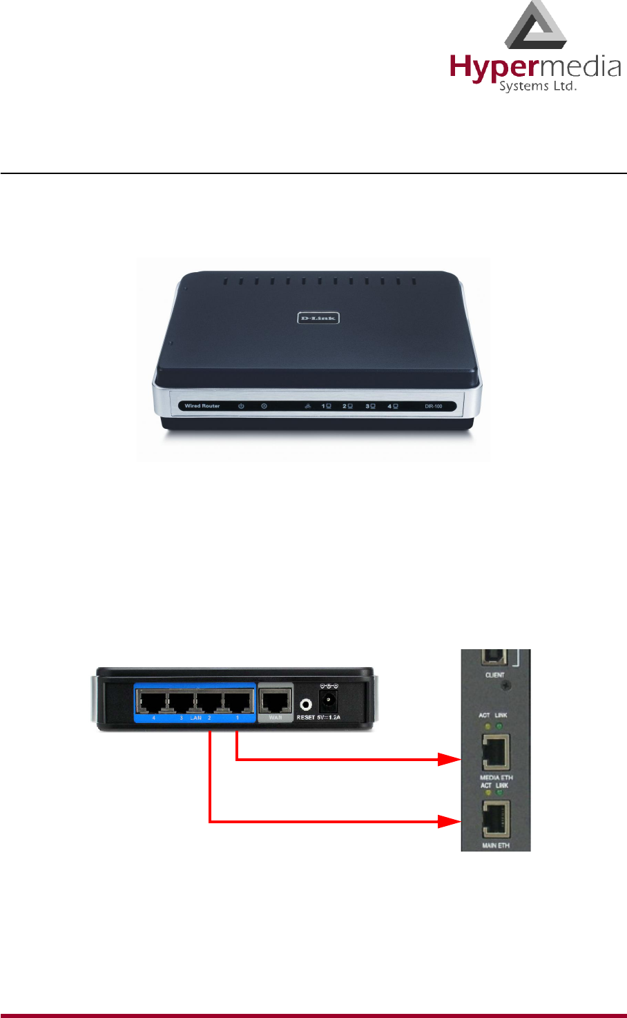
Figure 2: D-Link DIR 100 Router
System with a CB Card
If the system has a CB card, both D-Link Router cables attach to it.
a. Attach Port 1 of the D-Link Router to the Control Board (CB) port marked MEDIA
ETH.
b. Attach Port 2 of the D-Link Router to the Control Board (CB) port marked MAIN
ETH.
Figure 3: D-Link Connection for System with CB Card
c. Connect the D-Link’s WAN port to an appropriate network port.
MEDIA ETH
MAIN ETH

HMC Administrator’s Guide 9 Hardware and Installation
Release 3.4: May 2010 Installation
System without a CB Card
If the system does not have a CB card, connect the D-Link Router cables as follows:
a. Attach Port 1 of the D-Link Router to the MG card’s port marked ETHERNET.
b. Attach Port 2 of the D-Link Router to the PC card’s port marked LAN.
Figure 4: D-Link Connection for System with CB Card
c. Connect the D-Link’s WAN port to an appropriate network port.
2. Plug in the router and wait until its Status LED starts blinking green. This indicates that
the unit is functioning properly. A prolonged steady green light indicates a problem.
3. Configure the router.
a. Get the following information from your Internet Service Provider:
• WAN IP Address
• WAN Subnet Mask
• WAN Gateway,
b. Using a computer connected to the same LAN as the Hypermedia Gateway, open a
browser.
c. Configure the computer to automatically accept its IP address. This is done via the
Windows Network Connections tool. (Refer to Windows on-line Help and search for
DHCP.)
d. Enter the IP address of the DIR-100 into a browser’s Address field and press “Enter.”
The default IP address on a system using a CB is 192.168.9.254. The default IP
address on a system using a PC is 192.168.0.1. The Log In screen is displayed.
e. Enter the username admin and the password hypergateway.
f. Click Log In. The Setup Wizard is displayed.
g. Click Manual Internet Connection Setup.
To PC Card
To MG Card
HMC Administrator’s Guide 10 Hardware and Installation
Release 3.4: May 2010 Installation
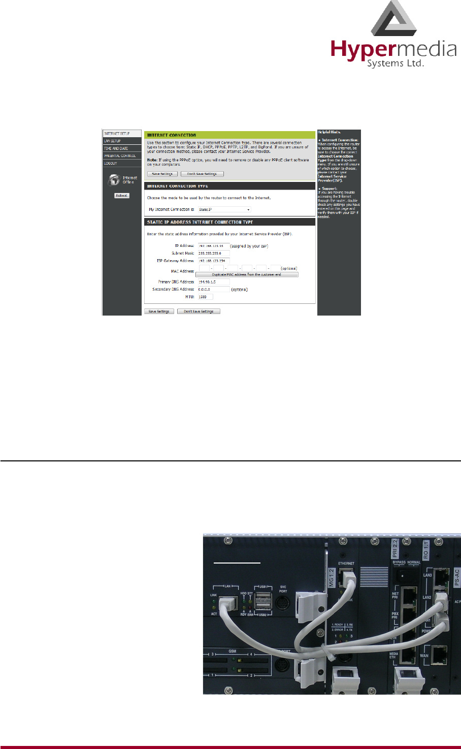
h. Click WA N . The Internet Connections screen is displayed.
Figure 5: D-Link Internet Connections Screen
i. Enter the WAN (Public) IP address information provided to you by your ISP.
j. Click Save Settings.
Note: For additional documentation, see the D-Link Manual found on the CD-ROM.
Installing the RO 1.1 Embedded Router Card
The RO 1.1 module is a single-slot card that provides Ethernet Broadband Router function-
ality. It is equipped with NAT network address translation technology and enables the Hyper-
media Gateway to connect to a public IP and to operate behind firewalls equipped with
Network Address Translation (NAT).
1. Connect a cable from the PC card’s
LAN port to the RO card’s LAN1
port.
2. Connect a cable from the MG
card’s ETHERNET port to the RO
card’s LAN2 port.
3. Configure the router. Begin con-
figuration with step 3 on page 9.
PC Card
HMC Administrator’s Guide 11 Hardware and Installation
Release 3.4: May 2010 Installation
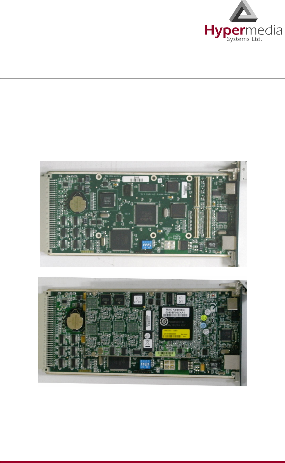
Installing the Media Gateway (MG) Card
The MG-1.1/1.2- Media Matrix is a single-slot card that enables flexible, pre-defined, and
dynamic allocation of GSM channels, E1 PRI B-channels, and VoIP channels. It comes in two
configurations:
• the basic Matrix slot board (pictured)
• VoIP Gateway add-on supporting the VoIP interface
Every Hypermedia Gateway system has an MG card. The MG card has an array of manual
Dual In-line Package (DIP) switches. Set them to match the system configuration.
Figure 6: MG Card 1.2 Without VoIP (above) and 1.1 (below) With VoIP
HMC Administrator’s Guide 12 Hardware and Installation
Release 3.4: May 2010 Installation
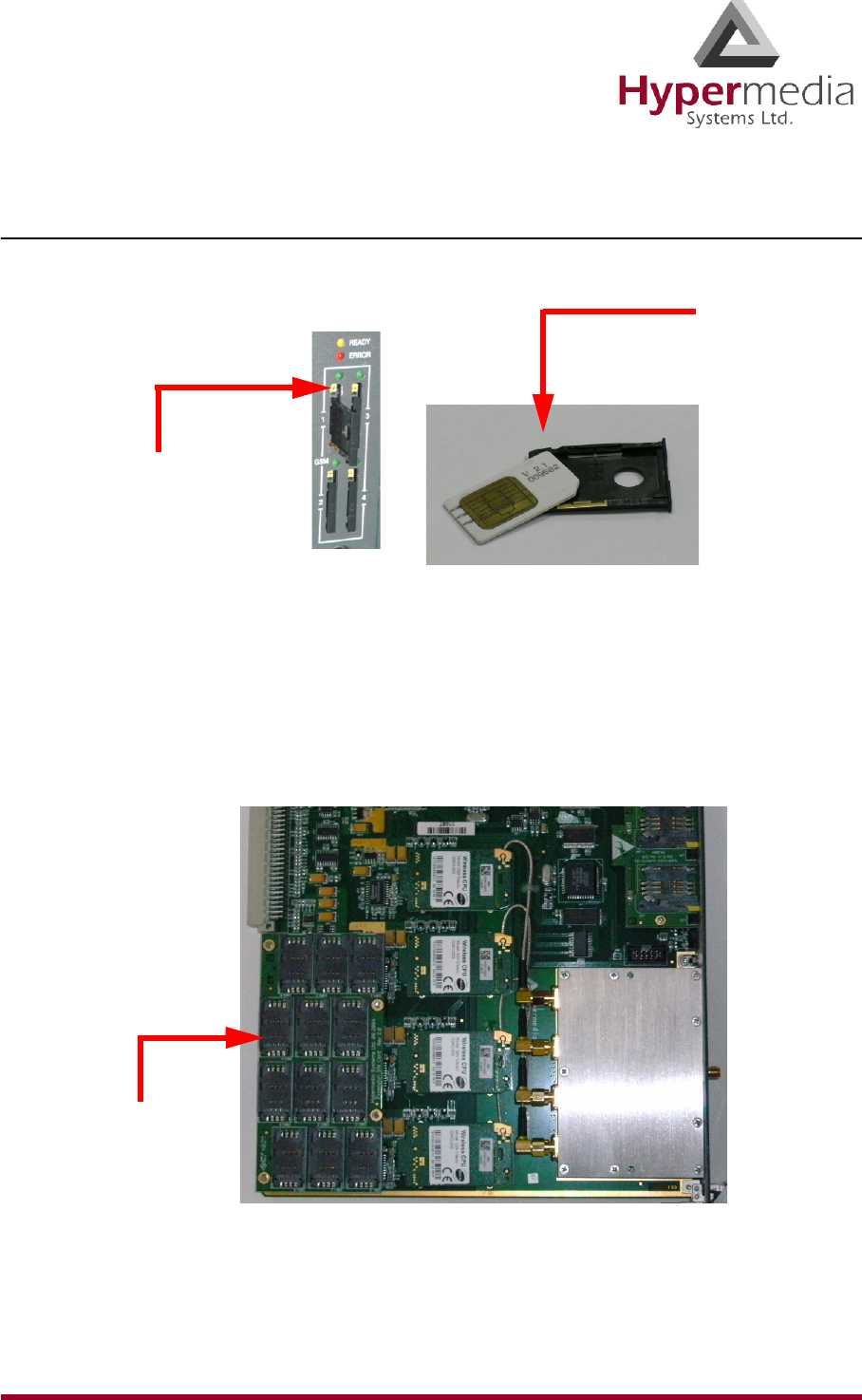
Installing the Cellular Card
1. Insert the GSM SIM Cards. One SIM card should be used per each cellular channel.
a. Push the small yellow button. This pushes SIM drawer out of the slot.
b. Remove the SIM drawer.
c. Place the SIM card in the SIM drawer.
d. Replace the SIM drawer.
e. Optionally, to use the CG board’s multi-SIM extender:
i. Pull out the CG board.
Figure 7: CG Card Multi-SIM Extender
ii. Slide back and pull up the SIM socket.
WARNING! Do not use force on the SIM sockets.
Push small,
yellow button
to extract the
SIM drawer.
Insert the SIM
card into the
SIM drawer.
Multi-SIM
Extender

HMC Administrator’s Guide 13 Hardware and Installation
Release 3.4: May 2010 Installation
iii. Slide in the SIM cards.
iv. Lock the SIM sockets.
2. Install the antennas. Each cellular card requires one antenna.
a. Locate the antenna socket ( ). The socket is above the SIM drawers.
b. Fasten the antenna using the SMA connector. Do not use excess force.
c. Tether all cables securely. Tethering helps prevents breakage of connectors and
damage to cellular cards.
WARNING! The antennas are for indoor use only. The antennas will be irreversibly
damaged if placed outdoors.
d. Place the antenna indoors, where the reception level is high.
e. Optionally, to improve reception, place the magnetic back of the antenna on a metal
plate larger than 20 x 20 cm.
HMC Administrator’s Guide 14 Hardware and Installation
Release 3.4: May 2010 Powering Up and LEDs
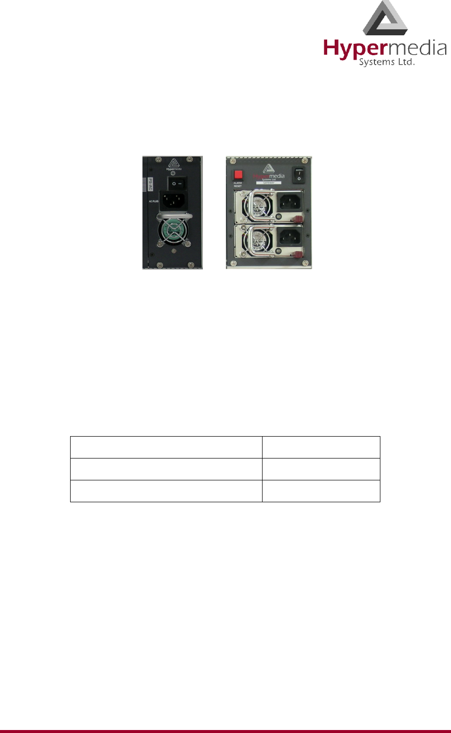
Powering Up and LEDs
1. Turn on the unit. The power panel is located at the top right corner of the system.
Figure 8: Power Panel
Note: Redundant power supplies are optional. When installed, if one fails, or if you power up
the system with just one power supply, an alarm will sound. To stop the alarm, press
the Alarm Reset button at the top left of the panel.
2. Check the LEDs. LED behavior is explained in the following tables:
Table 2: Table of LED Tables
MG Card’s Ethernet LEDs Table 3 on page 15
VoIP LEDs Table 4 on page 15
Cellular Card Green SIM LEDs Table 5 on page 16
HMC Administrator’s Guide 15 Hardware and Installation
Release 3.4: May 2010 LEDs
LEDs
Following are explanations of LED behavior for each of the Hypermedia Gateway’s cards.
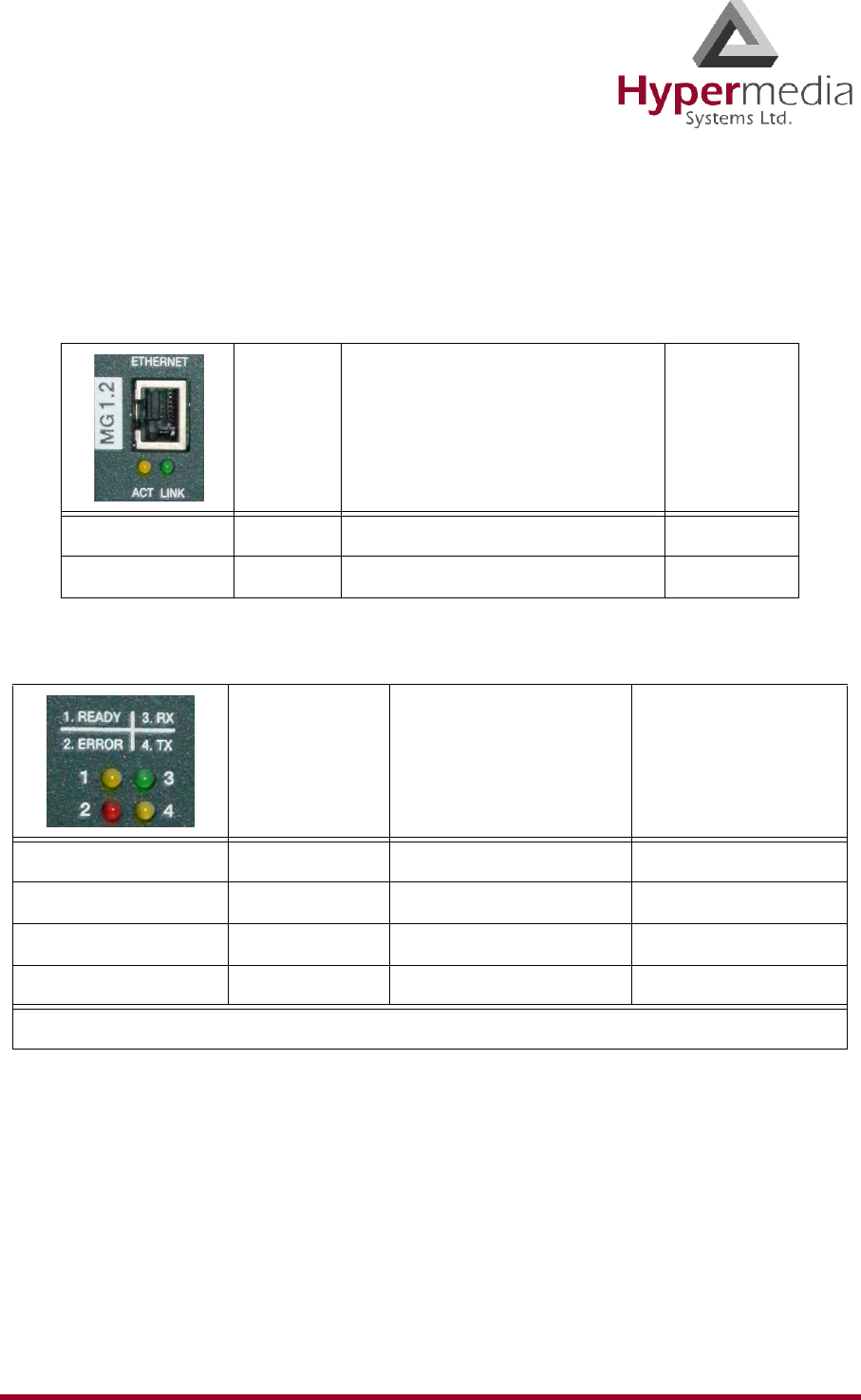
Table 3: MG Card’s Ethernet LEDs
Off On Blinking
ACT Active traffic
LINK LAN Connection established
Table 4: VoIP LEDs
Off On Blinking
Ready / Yellow Power is off Connected on 95% Maintenance mode
Error / Red Error
Rx / Green Internal communication
Tx / Yellow Internal communication
* The VoIP LEDs appear on the MG Card and the CB card.
HMC Administrator’s Guide 16 Hardware and Installation
Release 3.4: May 2010 LEDs
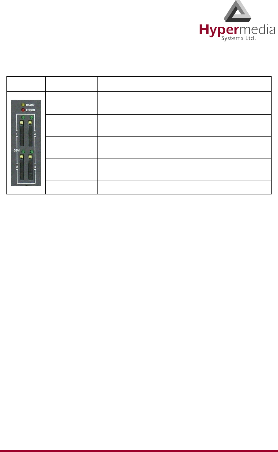
Table 5: Cellular Card Green SIM LEDs
State Explanation
Flashing No SIM card. The channel does not contain an installed
SIM card.
LED is off No reception. The channel is not connected to a cellular
network.
Short blink Stand by. The channel is connected but there is no call
in progress.
Long blink Dialing out or receiving a call. User is either dialing out
or receiving a call in this channel.
Constantly on In use. A call is in progress.

HMC Product Manual 17
Release 3.4: May 2010
Chapter 2
HMC QUICK START
Use the Hypermedia Management Console (HMC) to configure and monitor a Hypermedia
Gateway from a remote location. Access to the Gateway is over TCP/IP using a standard ver-
sion of Internet Explorer.
Note: The Hypermedia Management Console is customized to match the specific order.
Some branches of the HMC may or may not appear based upon the customization.
This section includes:
• “Installation” on page 18
• “Start-up and Initial Connection” on page 20
• “User Interface Overview” on page 23
• “HMC Navigation” on page 24
• “Save/Load Configuration” on page 26
• “Call Parameters” on page 27
HMC Product Manual 18
Release 3.4: May 2010 Installation
Installation
To install the Hypermedia Management Console program:
1. Ensure that the computer matches the following minimum system requirements:
• Windows 2000, XP, or Vista
• Internet Explorer 6 or 7
2. Ensure that you have access to the installation file. It is included with the Hypermedia
Gateway CD-ROM.
Figure 9: Hypermedia Gateway CD-ROM
The installation file name begins with the letter HMC and ends with the extension .exe.
The specific name depends upon the type of installation.
3. Double-click the file HMCxxx-xxx.exe file. The Setup program starts.
Figure 10: Setup Welcome Screen
4. Click Next. The License Agreement is displayed.
HMC Product Manual 19
Release 3.4: May 2010 Installation
5. To continue, you must accept the terms of the agreement. Click I accept the agreement
and click Next. The Select Destination Location window is displayed.
6. Define the location where the program files will be installed. The default location is
"C:\ProgramFiles\Hypermedia". Click Next. The Select Start Menu Folder is displayed.
7. Define the name of the program group that will be added to the Start Menu. The default
name is Hypermedia. Click Next. The Additional Tasks window is displayed.
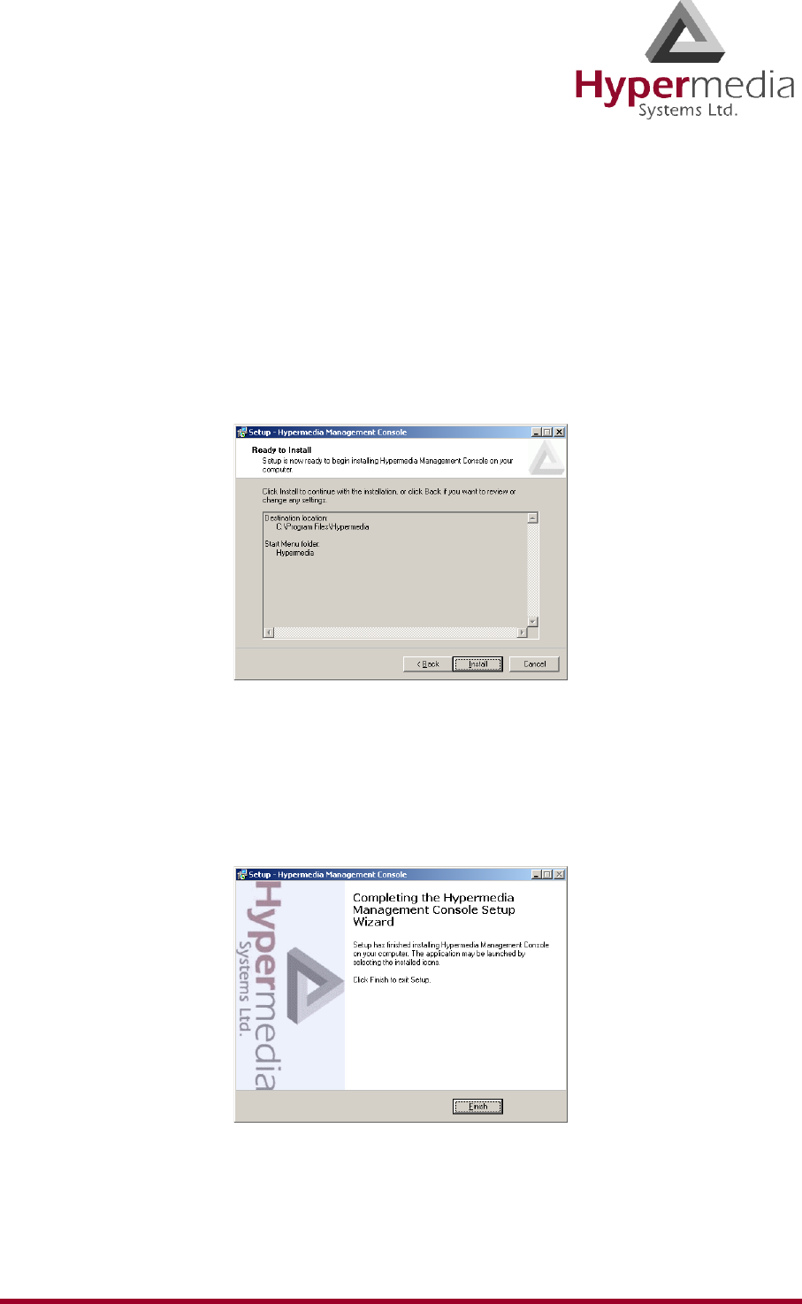
8. Optionally, select the checkbox to create a Desktop shortcut. Click Next. The Ready to
Install window is displayed.
Figure 11: Setup Ready to Install Screen
9. Click Install. The installation process begins. A progress bar reports on the progress of
the installation.
10. After the installation is complete, click Finish. The installation program creates a pro-
gram group in the Start menu and, optionally, a Desktop shortcuts.
Figure 12: Setup Finish Screen
HMC Product Manual 20
Release 3.4: May 2010 Start-up and Initial Connection
Start-up and Initial Connection
To run the Hypermedia Management Console:
1. Click the Windows Start button > Programs > Hypermedia. The Hypermedia program
group expands.
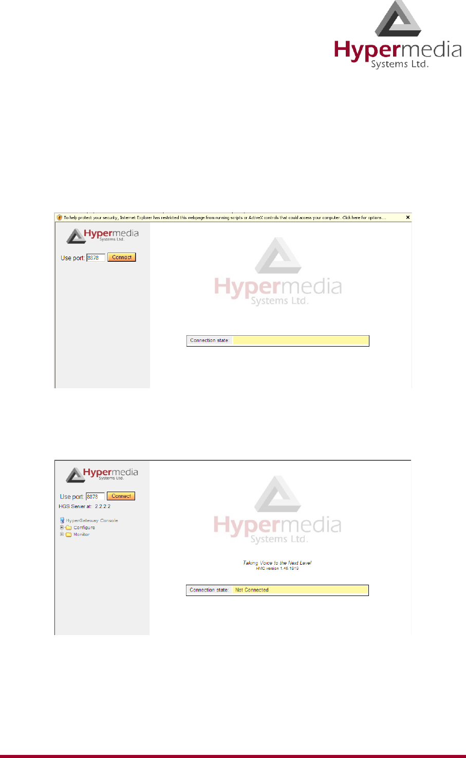
2. Click Hypermedia Management Console. The program opens in the default browser.
Figure 13: HMC Connection Screen
3. Click the warning bar at the top of the screen and, from the dropdown menu, click Allow
Blocked Content. Confirm your choice by clicking Ye s at the confirmation message.
Figure 14: HMC Connection Screen
Note: To avoid recurring displays of the warning bar, from the menu bar click Tools >
Internet Options > Advanced > Allow active content to run in files on My Computer.
HMC Product Manual 21
Release 3.4: May 2010 Start-up and Initial Connection
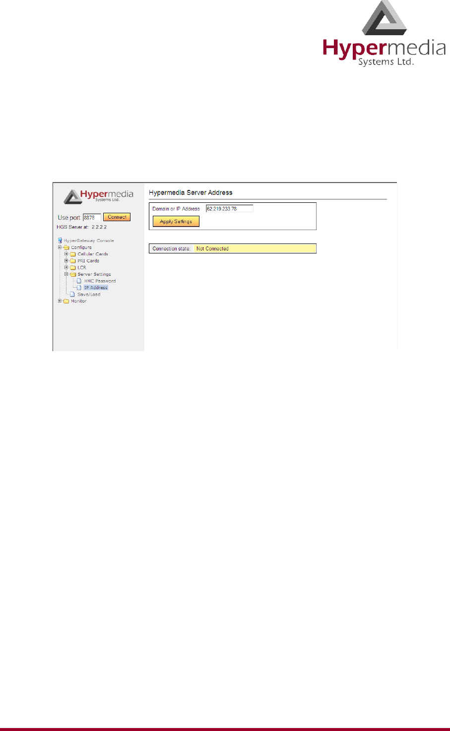
4. Enter the IP address:
a. Expand the Configure branch.
b. Expand the Server Settings branch.
c. Select IP address. The Server Address screen is displayed.
Figure 15: HMC Server Address Screen
Note: For a local connection, use the default IP address. The default address is 127.0.0.1.
For a remote connection, enter the remote IP address and use port 80.
d. Enter the IP address and click Apply Settings.
Note: If the Gateway is located behind a firewall, enable traffic on TCP port 8878. Contact
the network administrator for details.
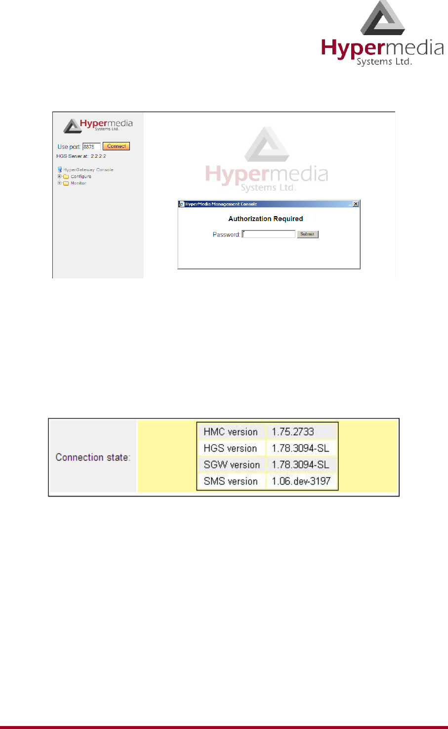
5. Either press F5 or click the browser’s Refresh button. The authorization screen is dis-
played.
HMC Product Manual 22
Release 3.4: May 2010 Start-up and Initial Connection
Figure 16: HMC Login Authorization Request
Note: The default password is admin.
6. Enter the password and click Submit. A confirmation message is displayed. The confir-
mation message indicates that you have successfully connected to the Hypermedia
Gateway.
Figure 17: HMC Connection State Display
HMC Product Manual 23
Release 3.4: May 2010 User Interface Overview
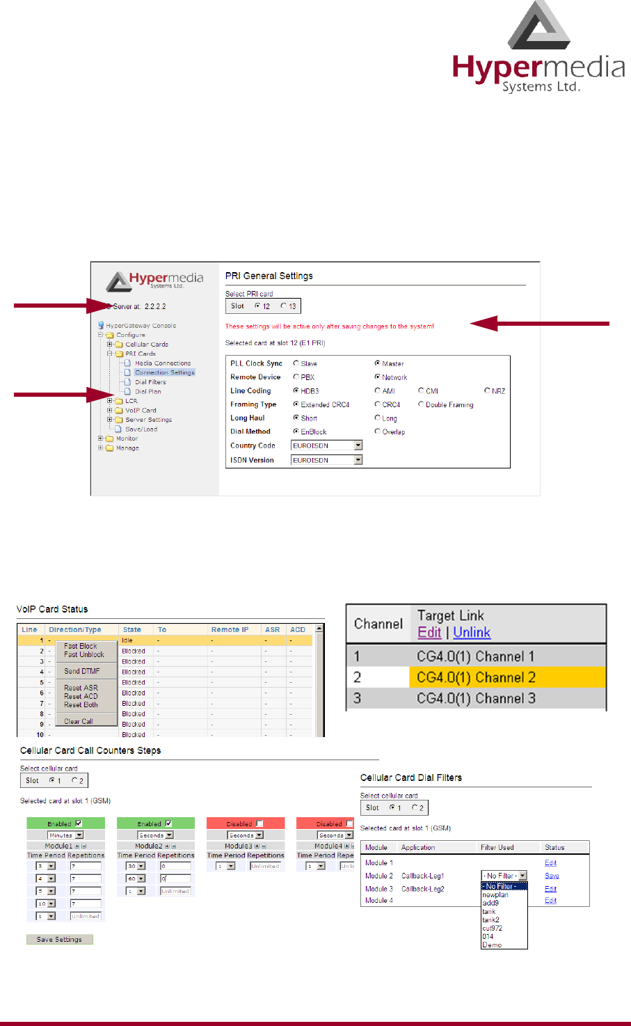
User Interface Overview
The Hypermedia Management Console opens in a browser. The interface is divided into a
Navigation Pane and a Configuration and Monitor Pane.
In addition, the interface includes identifying information.
Figure 18: The Hypermedia Management Console Interface
Popup and dropdown menus, are available from the Configuration and Monitor pane. Color is
used to indicate editing mode and changes of status.
Figure 19: Samples of the HMC Configuration and Monitor Pane
Navigation
Pane
Server IP
Address
Configuration and
Monitor Pane

HMC Product Manual 24
Release 3.4: May 2010 HMC Navigation
HMC Navigation
The Navigation Pane includes the branches and sub-branches from which access is gained to
the configuration, monitoring, management, and Save/Load panes.
Table 6: Summary of the Navigation Pane Branches and Sub-branches
Branch and Sub-branch Uses
Configure > SMS Server Open the SMS Server branch to configure SMS settings,
channels, and Advanced Call Routing (ACR).
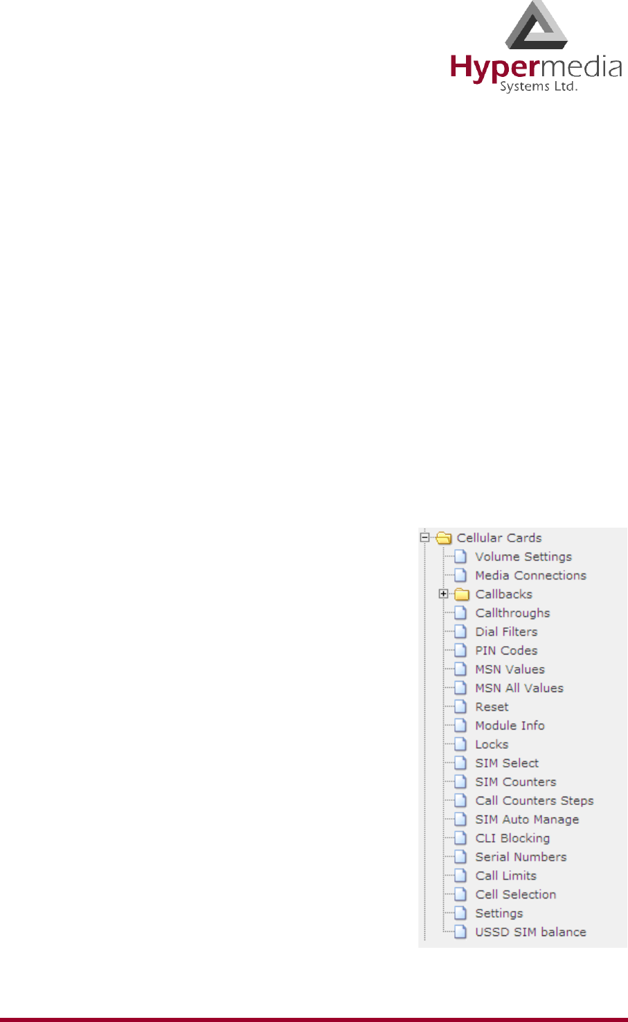
Configure > Cellular Cards
Open the Cellular Cards branch to configure parameters
controlling the cellular service. These parameters
include, for example, volume control and PIN codes.
Configure > LCR Cards
Open the LCR branch to configure Least Cost Routing
(LCR). Gateways with LCR route calls based on rules
created by the administrator. This results in per-call
routing. In contrast, when using gateways without LCR,
all call routes are fixed.
Configure > PRI Cards
Open the PRI Cards branch to configure parameters con-
trolling the connections between the digital PBX and the
Hypermedia Gateway and to configure the associations
between PRI channels and cellular cards.
Configure > BRI Cards
Open the BRI Cards branch to configure parameters
controlling the connections between the digital PBX and
the Hypermedia Gateway and to configure other param-
eters and settings affecting the BRI connection.
Configure > VoIP Cards
Open the VoIP Cards branch to configure connections
from a VoIP card to other cards and channels in the sys-
tem and to configure VoIP parameters.
Configure > Server Settings
Open the Configure > Server Settings branch to config-
ure the Hypermedia PRI Server’s IP address and the
Hypermedia Management Console’s password.
Configure > Save/Load
Open the Save/Load branch to store settings, save an
existing configuration, restore a saved configuration,
and delete a configuration.
Monitor > Cellular Cards Open the Monitor > Cellular Cards branch to view the
quality of the cellular card reception and their status.

HMC Product Manual 25
Release 3.4: May 2010 HMC Navigation
Monitor > PRI Cards Open the Monitor > PRI Cards branch to view the status
of each of the PRI channels.
Monitor > BRI Cards Open the Monitor > BRI Cards branch to view the status
of each of the BRI ports and the Bypass status.
Monitor > VoIP Cards
Open the Monitor > VoIP Cards branch to view the sta-
tus of VoIP lines, and to download a file containing VoIP
CDRs.
Monitor > LCR CDRs Open the Monitor > LCR CDRs branch to download a
file containing VoIP CDRs.
Manage > Number Filters
Open the Number Filters branch to perform advanced
manipulations on numbers that are sent to, or received
by, the Gateway.
Manage > Scheduler Open the Task Scheduler to configure the Gateway to
repeat commands at scheduled intervals.
Manage > VoIP
Open the VoIP Management branch to enhance the over-
all performance of the VoIP network. VoIP Management
Features enable you to restrict incoming calls, refine
routing, and review VoIP messages.
Table 6: Summary of the Navigation Pane Branches and Sub-branches
Branch and Sub-branch Uses
HMC Product Manual 26
Release 3.4: May 2010 Save/Load Configuration
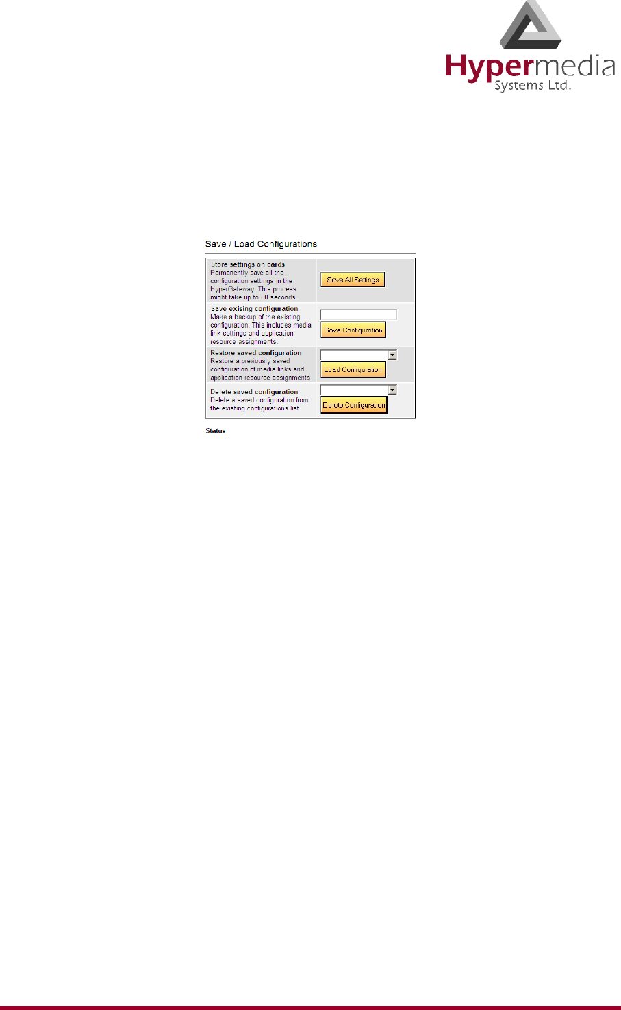
Save/Load Configuration
Use Save/Load Configuration branch to download and upload system settings via a configura-
tion file.
Figure 20: HMC Save and Load Options
There are four possibilities:
Store settings on cards
Use this option to write the entire configuration onto the Flash Memory of the slot’s
module, that is, to permanently save all the configuration settings in the Hypermedia
Gateway. This process might take up to 60 seconds.
Save existing configuration
Use this option to make a backup of the existing configuration. This option backs-up
media link settings and application resource assignments.
Restore saved configuration
Use this option to restore a previously saved configuration of media links and application
resource assignments.
Delete saved configuration
Use this option to delete a saved configuration from the existing configurations list.
HMC Product Manual 27
Release 3.4: May 2010 Call Parameters
Call Parameters
Use the Call Parameter branch to configure parameters affecting Callback and Callthrough and
general parameters effecting the Media Card.
To define Call Parameters:
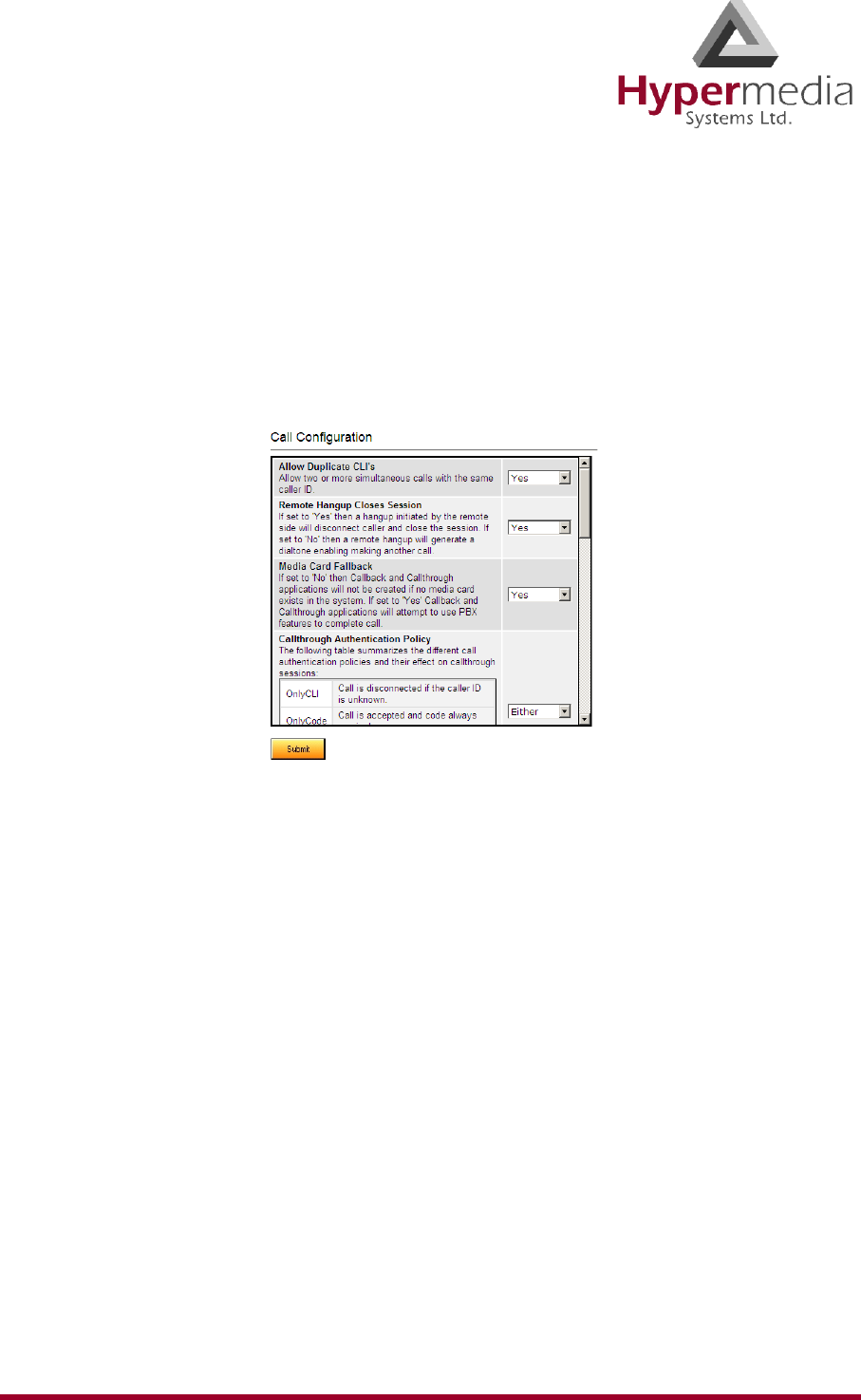
1. From the Configure branch of the HMC navigation pane, click the Call Parameters sub-
branch. The Call Configuration screen is displayed.
Figure 21: HMC Call Configuration Screen
2. Configure the following parameters:
Allow Duplicate CLIs
If Yes is selected, the Gateway allows two or more simultaneous calls with the same caller
ID.
Remote Hang up Closes Session
Is Yes is selected, a hang-up initiated by the remote side will disconnect the caller and
close the session. If No is selected, a remote hang-up will generate a dial tone enabling
the user to make another call.
Media Card Fallback
If No is selected, Callback and Callthrough applications will not be created if the system
does not include a Media Card. If Yes is selected, Callback and Callthrough applications
will attempt to use the PBX’s features to complete the call.
Callthrough Authentication Policy
From the dropdown menu, select an option described in the table of authentication
policies.
Callback Authentication Policy
If Yes is selected, users are required to enter a personal access code when receiving
callbacks.

HMC Product Manual 28
Release 3.4: May 2010 Call Parameters
Callback Dial Timeout
Enter a period of time, measured in milliseconds, during which the Gateway will attempt
to call the party that requested a Callback.
Remote Party Answer Timeout
Enter a period of time, measured in milliseconds, during which the Gateway will attempt
to call the remote party.
Number Send Delay
Entered a period of time, measured in milliseconds, after which a dialed number will be
automatically sent. This parameter applies only when the Media Card is present.
Dial tone Length
Enter a period of time, measured in milliseconds, during which the dial tone is played for
Callthrough or Callback sessions. This parameter applies only when the Media Card is
present.
Callback Automatic DTMF Send Delay
Enter a period of time, measured in milliseconds, after which the automatic DTMF
sequence is sent when the Callback returns call (if one is defined for the callback number).
This parameter applies only when the Media Card is present.
Callback Automatic DTMF Digit Duration
Entered a period of time, measured in milliseconds, which determines the length of a
DTMF digit sent for automatic Callback DTMF digits.
Callback Automatic Inter-Digit Duration
Enter a period of time, measured in milliseconds, that defines the period of silence
between DTMF digits sent for automatic Callback DTMF digits.
Delay after DTMF Code is Sent
Enter a period of time, measured in milliseconds, that determines the delay before the
Gateway dials the second leg of the callback (if a DTMF code is sent to the first leg of the
call).
Callback Activation/Delegation Delay
Enter period of time, measured in milliseconds, which determines how long the Gateway
waits before returning a Callback to a requesting phone or delegating a Callback request
to a remote HGS. This is used so that the remote Callback will not be triggered too early,
which can possibly result in receiving a busy signal from the endpoint that requested it.
Enable Using Callthrough Resources for Callbacks
If No is selected, only Callback resources are used to dial callback. If Yes is selected, the
Gateway attempts to use Callthrough resources if a Callback is requested but no Callback
resources are available.
3. Click Submit and wait for the “Successfully updated … Server refresh returned: OK”
messages.
HMC Product Manual 29
Release 3.4: May 2010
Chapter 3
CONFIGURING a CELLULAR CARD
This section contains:
• “Cellular Card and System Terminology” on page 30
• “Volume Settings” on page 31
• “Media Connections” on page 32
• “Callbacks” on page 34
• “Callthroughs” on page 37
• “Dial Filters” on page 39
• “PIN Codes” on page 40
• “MSN Values” on page 41
• “Reset” on page 42
• “Information Screens” on page 43
• “Locks” on page 44
• “SIM Select” on page 45
• “SIM Counters” on page 46
• “SIM Auto Manage” on page 47
• “Call Counter Steps” on page 48
• “CLI Blocking” on page 49
• “Call Limits” on page 50
• “Cell Selection” on page 51
• “Settings” on page 54
• “USSD SIM Balance” on page 53
• “Monitoring Cellular Cards” on page 55
Note: The HMC is customized
to match the specific order.
Some branches of the HMC
may or may not appear based
upon the customization.
HMC Product Manual 30
Release 3.4: May 2010 Cellular Card and System
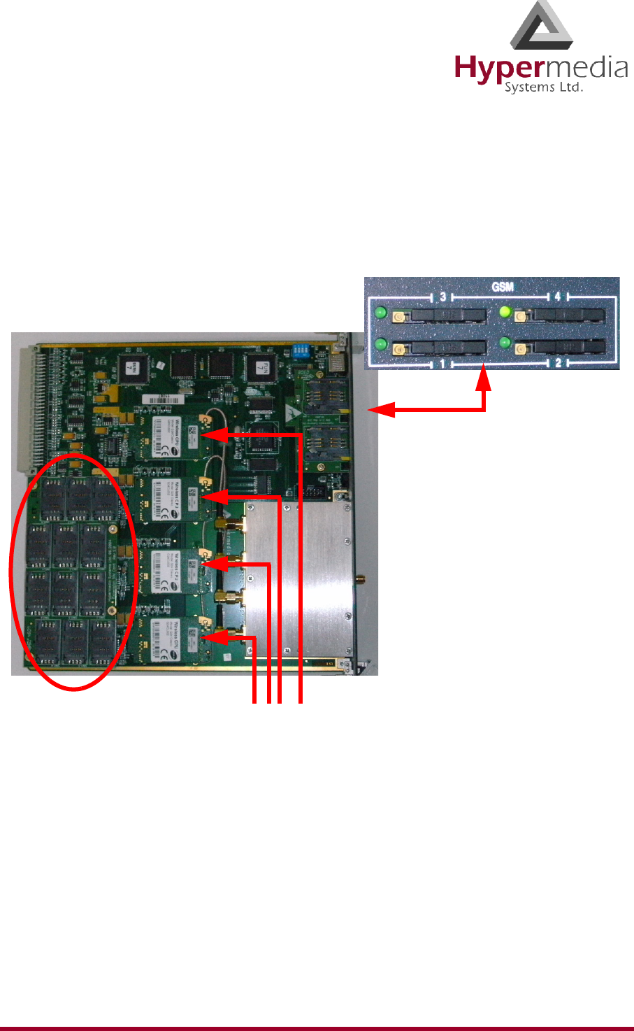
Cellular Card and System Terminology
A cellular card has 4 modules, each of which can have 1 to 4 SIM holders. Therefore, each
card can hold up to 16 SIM cards. In addition, a Hypermedia Gateway can include several
SIM cards.
Some parameters can be applied either to specific SIM cards, or to specific modules, or to the
entire cellular card, or to all the cards in the system.
The first SIM cards of each
module are loaded from the
front of the Cellular Card.
Additional SIM cards are
loaded at the rear of the
Cellular Card.
Controllers
for modules
1 through 4
HMC Product Manual 31
Release 3.4: May 2010 Volume Settings
Volume Settings
Use Volume Settings to adjust a cellular module’s audio level. This can be done for each of the
cellular modules on a Hypermedia Gateway.
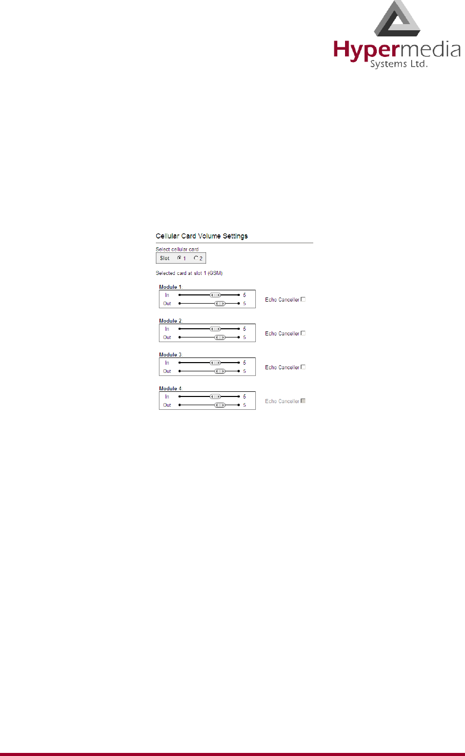
To adjust the audio level:
1. From the Cellular Cards branch of the HMC navigation pane, click the Volume Settings
sub-branch. The Volume Settings screen is displayed.
Figure 22: HMC Volume Settings Screen
2. If more than one slot is displayed, select a specific Cellular Card. The Volume Settings
screen of that cellular card is displayed.
3. To increase the volume, move the slider to the right. Each module includes two sliders:
In
“In” adjusts the volume heard by the party on the PBX (or local network) side of the
conversation.
Out
“Out” adjusts the volume heard by the remote party.
Note: Changes to volume are saved automatically. The message “New volumes set
successfully” is displayed.
4. Select or clear the Echo Canceller checkbox. There are several different causes of the
echo effect. Selecting Echo Canceller minimizes or cancels the echo effect.
5. After enabling Echo Canceller, from the HMC navigation pane, click the Save/Load
branch and then click Save All Settings.
HMC Product Manual 32
Release 3.4: May 2010 Media Connections
Media Connections
Use the Media Connection screen to configure the connections from the channels of a Cellular
card to other cards and channels in the system, including the PRI cards (E.1) and the VoIP
cards (MG). Connections can be either static or dynamic, as in the case of LCR.
For example, you can assign each cellular channel to a specific E1 channel. In this case, every
time there is an incoming call from a specific E1 channel, it will be routed to the configured
channel on the cellular card and vice versa.
Note: The matrix can be configured in any combination. Routing can be assigned between
any cellular channel and any other channel in the system, including other cellular
channels.
Associating/Linking Cellular Channels
To associate a cellular channel with another media channel:
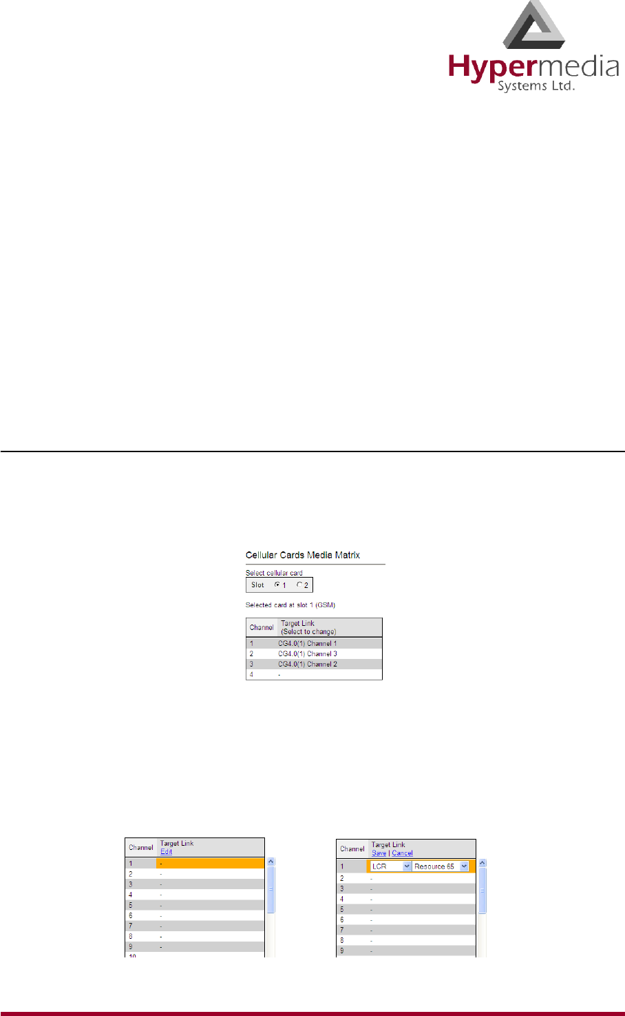
1. From the Cellular Cards branch of the HMC navigation pane, click the Media Connec-
tions sub-branch. The Media Matrix is displayed.
Figure 23: Cellular Media Matrix screen
2. If more than one slot is displayed, select a specific cellular card. The Media Matrix of that
cellular card is displayed.
3. Click within a channel row. The row turns yellow.
4. Click Edit. The row becomes configurable.
Figure 24: Media Matrix Row when Configurable
HMC Product Manual 33
Release 3.4: May 2010 Media Connections
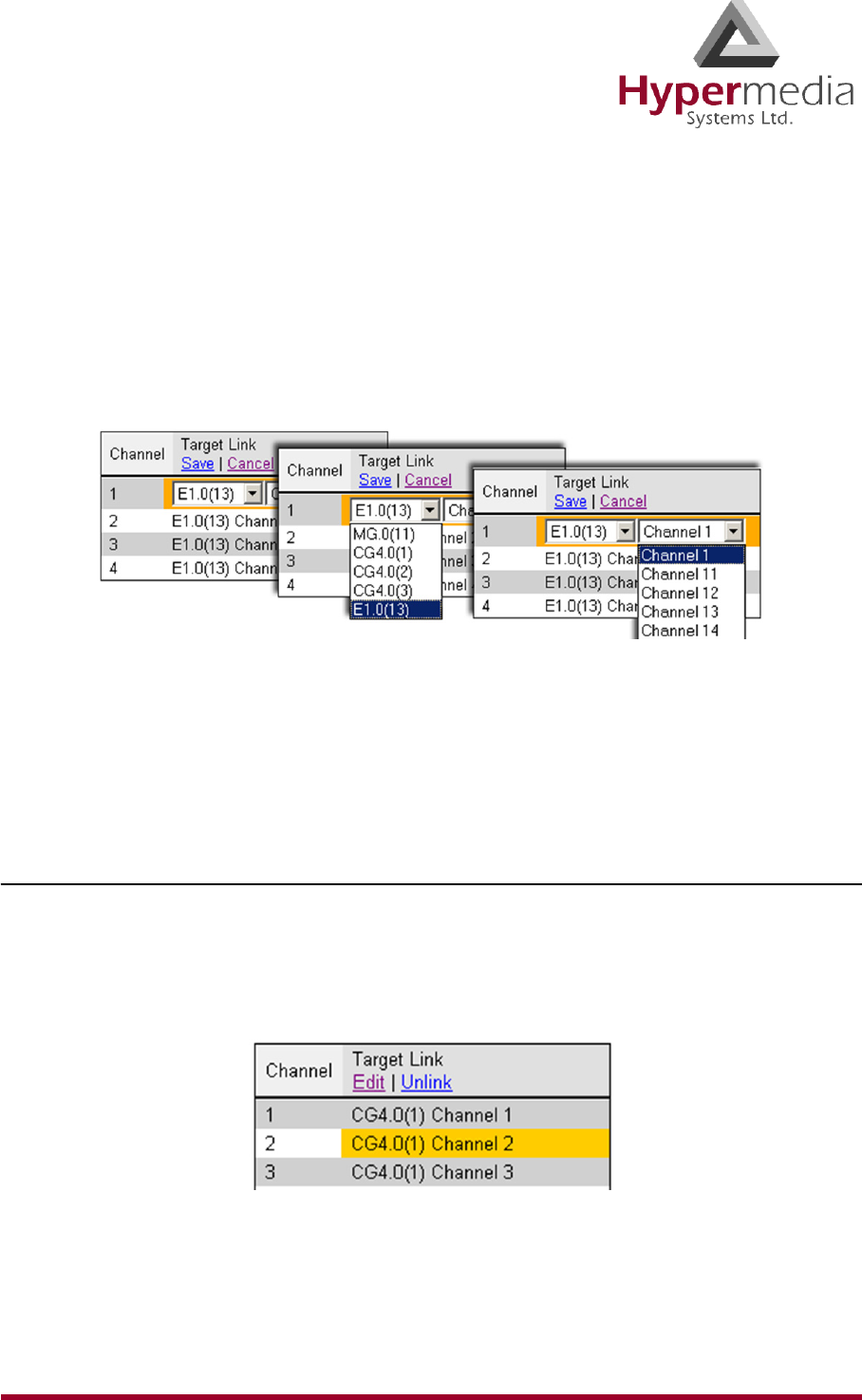
5. From the first dropdown list, allocate this channel to a card by selecting the card.
Note: If all of the card’s channels are already allocated, the message “Fully allocated”
appears.
6. From the second dropdown list, assign this channel to a specific channel on the target
card.
Figure 25: Assigning a Target Link
7. Click Save. The configuration dropdown boxes are hidden.
8. Optionally, repeat the process for additional channels and other media types.
9. Click Apply Settings and wait for Configuration Saved to be displayed.
Unlinking Cellular Allocations
To break an allocation:
1. From the Cellular Card branch of the HMC navigation pane, click the Media Connec-
tions sub-branch. The Media Matrix is displayed.
2. Click within a channel row. The row turns yellow.
Figure 26: Breaking a Target Link
3. Click Unlink.
4. Click Apply Settings and wait for Configuration Saved to be displayed.
HMC Product Manual 34
Release 3.4: May 2010 Callbacks
Callbacks
Use Callback to cause the Gateway to authorize an incoming call, disconnect the incoming
call, and then call-back the User. A Callback is initiated by a trigger. The trigger can be either
a phone call, an SMS message, or a message sent via the Hypermedia Web-based Callback
dialer.
Note: Callback belongs to the Hypersavings Package and requires a separate license.
Resources
For a Resource to be available for Callback, it must be linked to itself. Then, Resources must
be allocated to the Callback feature. To allocate resources to Callback:
1. Ensure that at least one Cellular Card > Media Connection channel is linked to a Cellular
Gateway (CG) and is unallocated (see “Media Connections” on page 32).
2. From the HMC navigation pane’s Cellular branch, expand the Callbacks sub-branch.
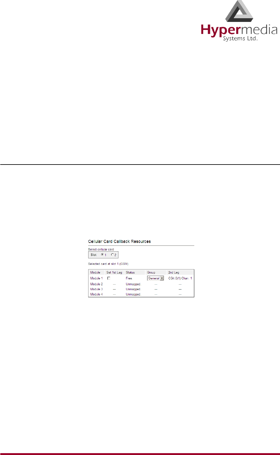
3. Click Resources. The Resources screen is displayed.
Figure 27: HMC Cellular Resources Screen
4. Select a Resource’s Set 1st Leg checkbox. When selected, this Resource can accept Call-
back requests. Also, when selected, this Resource is not used for standard calls.
Note: To clear a checkbox, from the Cellular Card Media Connection branch, select the
channel and click Unlink.
5. From the Group dropdown list, select the Group that will be allowed to use this Callback
Resource. These are the Groups that are defined in the VPN Groups sub-branch of the
Manage branch.
Note: The 2nd Leg column displays the channel used for the 2nd leg of the Callback.
HMC Product Manual 35
Release 3.4: May 2010 Callbacks
6. Repeat the procedure for other Resources that will be allocated to Callback calls.
7. Click Apply Settings and wait for Configuration Saved to be displayed.
Call Triggers
Use Call Triggers to configure the gateway to respond to a call to a specific channel as a Call-
back request.
1. Ensure that at least one Cellular Card > Media Connection channel is linked to a Cellular
Gateway (CG) and is unallocated (see “Media Connections” on page 32).
2. From the HMC navigation pane’s Cellular branch, expand the Callbacks sub-branch.
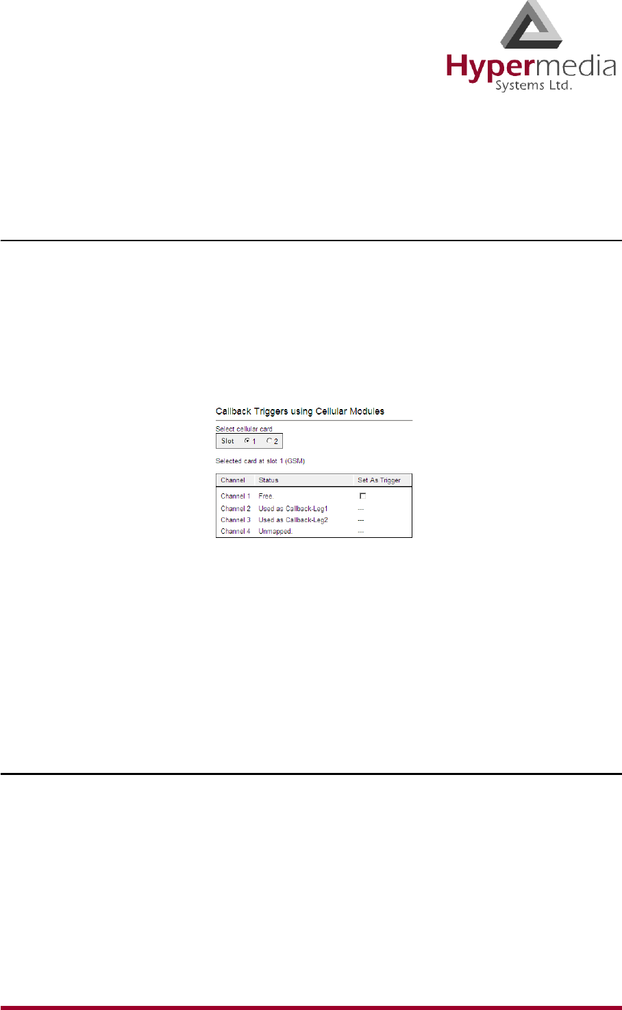
3. Click Call Triggers. The Callback Triggers screen is displayed.
Figure 28: HMC Cellular Call Triggers Screen
4. Select the checkbox. When selected, the channel is allocated to Callback.
Note: To clear a checkbox, from the Cellular Card Media Connection branch, select the
channel and click Unlink.
5. Click Apply Settings and wait for Configuration Saved to be displayed.
SMS Triggers
Use the SMS Triggers screen to enable use of SMS messages to command the Gateway to call
back the party who sent the SMS message.
Note: The SMS message must contain the telephone number that the Gateway is to call.
To enable use of SMS triggers:
1. From the HMC navigation pane’s Cellular branch, expand the Callbacks sub-branch.
2. Click the SMS Triggers sub-branch. The SMS Triggers screen is displayed.

HMC Product Manual 36
Release 3.4: May 2010 Callbacks
Figure 29: HMC SMS Triggers Screen
3. If more than one slot is displayed, select a specific Cellular Card. The SMS Trigger
screen of that cellular card is displayed.
4. Optionally, select a Number Filter (see “Number Filters” on page 125).
5. Select or clear the checkbox for each module. When selected, an SMS from the user to a
SIM card on that module will initiate a Callback.
6. Click Apply Settings and wait for Configuration Saved to be displayed.
HMC Product Manual 37
Release 3.4: May 2010 Callthroughs
Callthroughs
Use Callthrough to place calls, via the Hypermedia Gateway, to external numbers.
Note: Callthrough belongs to the Hypersavings Package and requires a separate license.
Users receive a dial-tone from the Hypermedia Gateway and can then place calls either:
• via the PBX to a corporate extension
• to a VoIP phone number
• to a Cellular phone number
• to a PSTN phone number
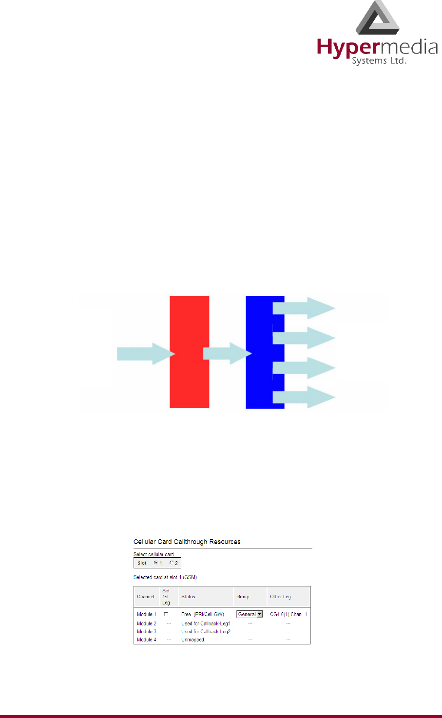
Figure 30: The Callthough Sequence
To configure Callthrough:
1. Ensure that at least one Cellular Card > Media Connection channel is linked to the target
Callthrough equipment and is unallocated (see “Media Connections” on page 32).
2. From the Cellular Cards branch of the HMC navigation pane, click the Callthrough sub-
branch. The Callthrough screen is displayed.
Figure 31: The Callthrough Screen
1st Leg 2nd Leg
PBX
Cellular
HyperGateway
}
VoIP
Cellular
PSTN
VoIP
PSTN

HMC Product Manual 38
Release 3.4: May 2010 Callthroughs
3. Select a Module’s Set 1st Leg checkbox. When selected, this Module can accept
Callthrough calls from the user. Also, when selected, this Module is not used for standard
calls.
Note: To clear a checkbox, from the Cellular Card Media Connection branch, select the
channel and click Unlink.
4. From the Group dropdown list, select the Group that will be allowed to use this
Callthrough Resource. These are the Groups that are defined in the VPN Groups sub-
branch (see “VPN Groups” on page 124).
Note: The Other Leg column displays the equipment used for the 2nd leg of the Callthrough.
5. Repeat the procedure for other Resources that will be allocated to Callthrough calls.
6. Click Apply Settings.
HMC Product Manual 39
Release 3.4: May 2010 Dial Filters
Dial Filters
Filters enable consistent, automatic management of phone numbers before they are routed.
Note: The Dial Filters feature is relevant only to Hypermedia HG4000 Gateways.
Filters are created on the Manage > Number Filters screen (see “Number Filters” on
page 125).
Cellular card’s Dial Filters can be used only if linked to a VoIP channel or used with
Callback/Callthrough features.
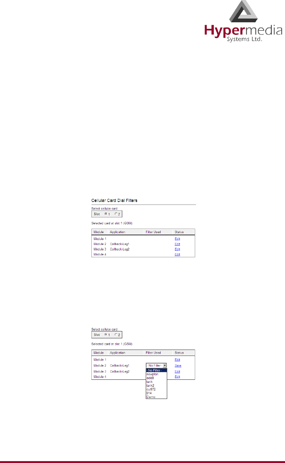
To apply a dialing filter to a module:
1. From the Cellular Cards branch of the HMC navigation pane, click the Dial Filters sub-
branch. The Cellular Card Dial Filters screen is displayed.
Figure 32: Cellular Card Dial Filters Screen
2. If more than one slot is displayed, select a specific Cellular card. The Dial Filters of that
Cellular card are displayed.
3. Click Edit. A dropdown list of existing filters is displayed.
4. Expand the list and select a filter.
Figure 33: Filters Dropdown List
5. Click Save.
6. Click Apply Settings and wait for Configuration Saved to be displayed.
HMC Product Manual 40
Release 3.4: May 2010 PIN Codes
PIN Codes
Use the PIN Codes screen to configure the PIN code that the gateway uses when a SIM card
with an active PIN is inserted. Consult your cellular provider for more information regarding
the PIN code.
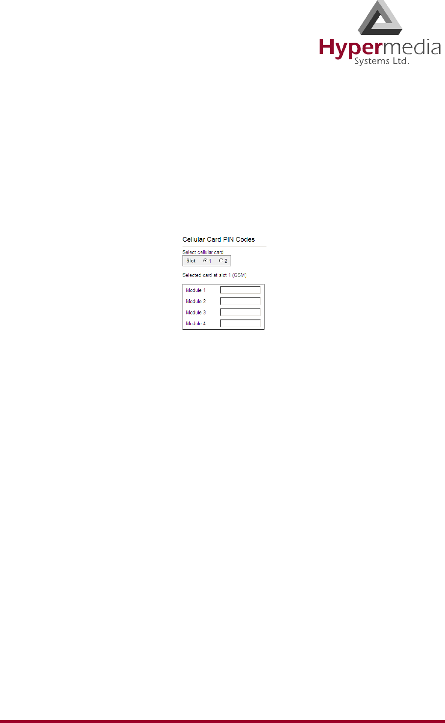
To enter a SIM card’s PIN code:
1. From the Cellular Cards branch of the HMC navigation pane, click the PIN Codes sub-
branch. The PIN Codes screen is displayed.
Figure 34: HMC Cellular PIN Codes Screen
2. If more than one slot is displayed, select a specific Cellular Card. The PIN Codes screen
of that cellular card is displayed.
3. Enter the PIN code into the associated Module’s field.
4. Click Apply Settings and wait for Configuration Saved to be displayed.
HMC Product Manual 41
Release 3.4: May 2010 MSN Values
MSN Values
Use Multiple Subscriber Number (MSN) values to route incoming calls to a specific extension
on the PBX. You can assign a different extension for each channel or route all channels to the
same extension.
Note: Hypermedia’s use of MSN differs from the traditional ISDN use. MSN is an incoming
call routing method in which a group of phone numbers is assigned to a particular PRI
ISDN line by the telephone company.
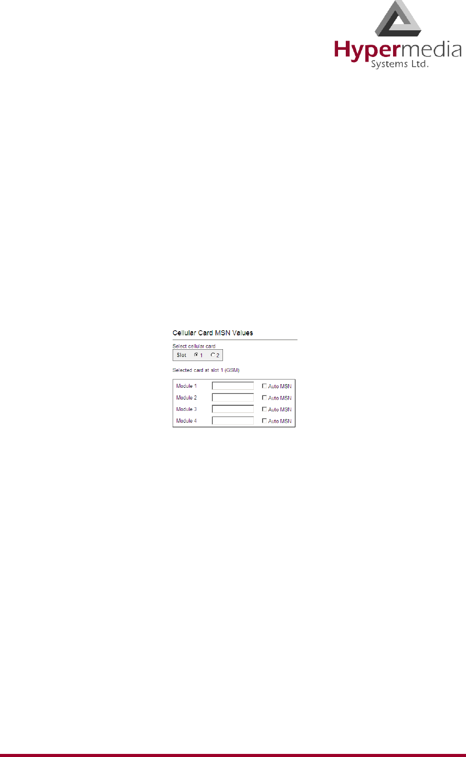
To route incoming calls to a specific extension on the PBX:
1. From the Cellular Cards branch of the HMC navigation pane, click the MSN Values sub-
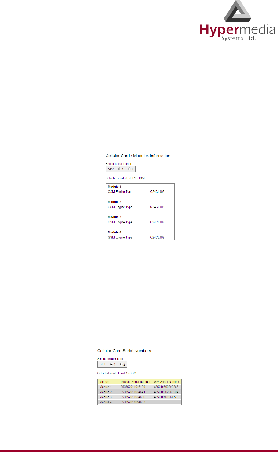
branch. The MSN Values screen is displayed.
Figure 35: Cellular MSN Values
2. If more than one slot is displayed, select a specific Cellular Card. The MSN Values screen
of that cellular card is displayed.
3. Enter a PBX extension number.
4. Select or clear the Auto MSN checkbox. When selected, if a local user “A” called a
remote user “B” through a cellular module and later “B” calls the cellular module’s
number, the system will automatically route the incoming call to “A”. The system
remembers that “A” was the last local user to call “B” through that cellular module.
5. Click Apply Settings and wait for Configuration Saved to be displayed.
HMC Product Manual 42
Release 3.4: May 2010 Reset
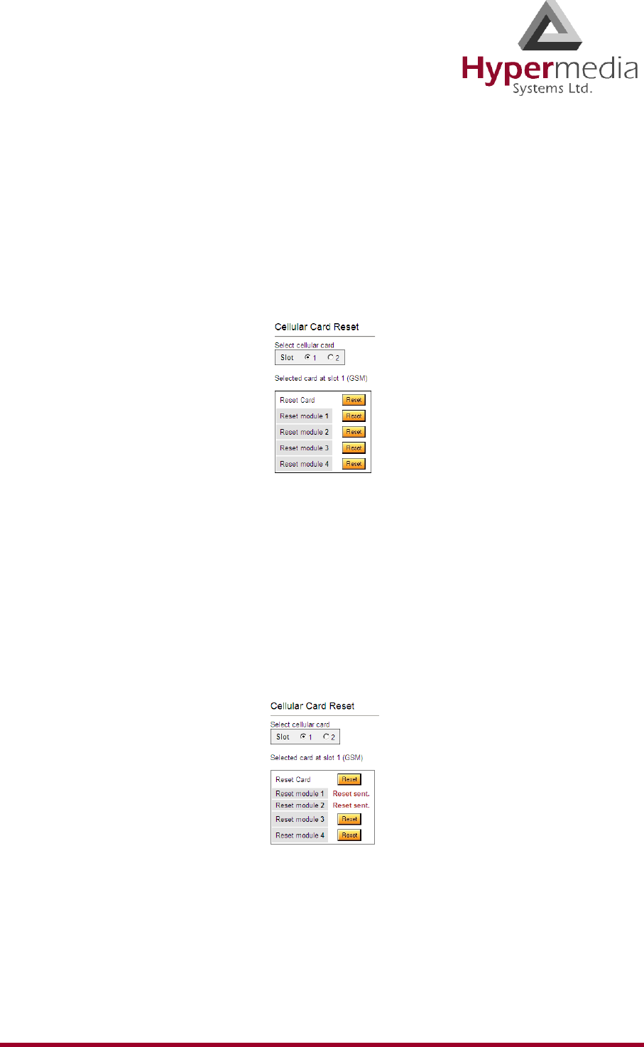
Reset
Use the Cellular Card Reset screen to reset either the entire cellular card or a specific cellular
module.
To reset a cellular card or module:
1. From the Cellular Cards branch of the HMC navigation pane, click the Reset sub-branch.
The Reset screen is displayed.
Figure 36: Cellular Card Reset screen
2. If more than one slot is displayed, select a specific Cellular Card. The Reset screen of that
cellular card is displayed.
WARNING! There is no confirmation message. The Reset command is sent as soon as the
reset button is clicked.
3. Click Reset. The screen confirms that the Reset command has been sent.
Figure 37: Reset Screen After Sending the Reset Command
HMC Product Manual 43
Release 3.4: May 2010 Information Screens
Information Screens
Several of the HMC screens display information.
Module Info
Use the Module Info screen to review information about the modules of a cellular card.
1. From the Cellular Cards branch of the HMC navigation pane, click the Module Info sub-
branch. The Module Info screen is displayed.
Figure 38: HMC Module Info Screen
2. If more than one slot is displayed, select a specific Cellular Card. The Module Info screen
of that cellular card is displayed.
Serial Numbers
Use the Serial Numbers screen to view the GSM Modules IMEI (International Mobile Equip-
ment Identity) and the SIMs IMSI (International Mobile Subscriber Identity).
1. From the Cellular Cards branch of the HMC navigation pane, click the Serial Numbers
sub-branch. The Serial Numbers screen is displayed.
Figure 39: HMC Serial Numbers Screen
2. If more than one slot is displayed, select a specific Cellular Card.
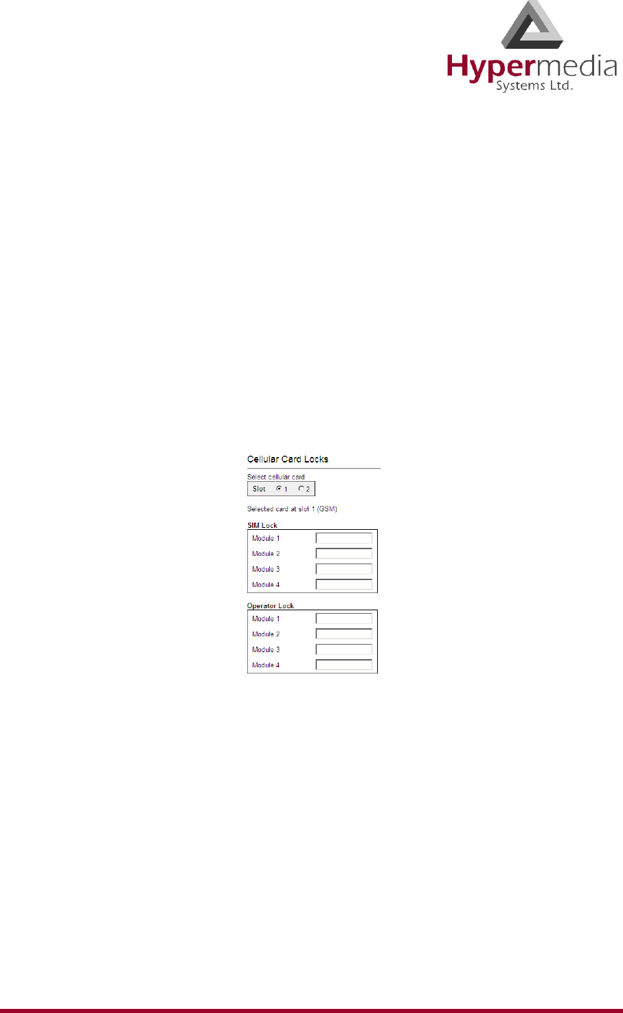
HMC Product Manual 44
Release 3.4: May 2010 Locks
Locks
Use Locks to restrict access to specific GSM operators and/or a specific SIM card. When a
lock is defined, the Gateway will only accept calls from an operator or a SIM card that matches
the Lock number.
In addition, use Locks to prevent roaming handover in cases where the Gateway is located
close to county or country borders.
To define a Lock number:
1. Ensure that:
• you have obtained the codes from the cellular operator
• the cellular modules support SIM locks
2. From the Cellular Cards branch of the HMC navigation pane, click the Locks sub-branch.
The Locks screen is displayed.
Figure 40: HMC Cellular Locks Screen
3. If more than one slot is displayed, select a specific Cellular Card. The Locks screen of
that cellular card is displayed.
4. Enter:
SIM Lock
Use SIM Locks to avoid using SIM cards other than those whose Mobile Network Code
(MNC) and Mobile Country Code (MCC) values have been entered.
Operator Lock
Use Operator Locks to avoid registration to any network other than the one whose MNC
and MCC values have been entered.
5. Click Apply Settings and wait for Configuration Saved to be displayed.
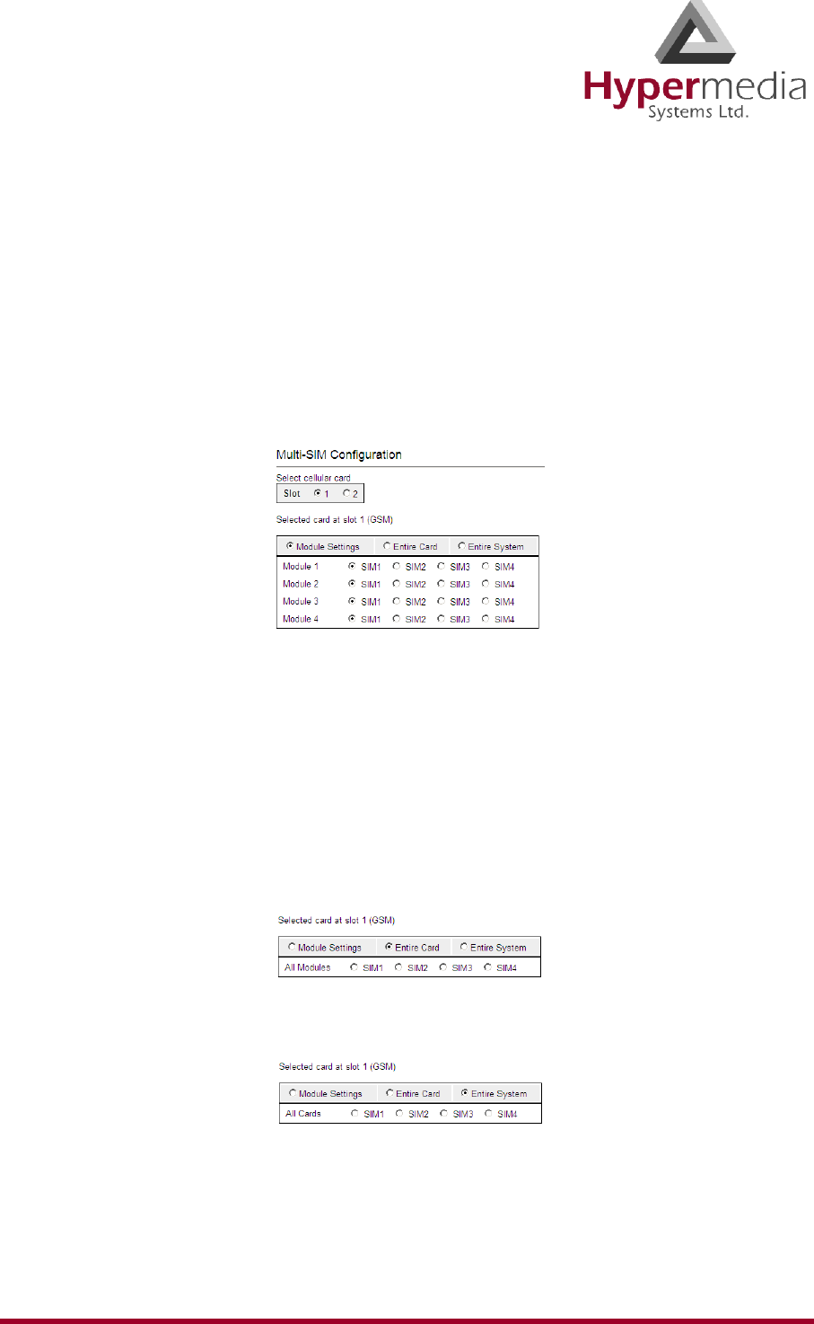
HMC Product Manual 45
Release 3.4: May 2010 SIM Select
SIM Select
Use the SIM Select screen to manually select and activate a SIM card for current use. SIM
Select should not be used when SIM Auto-Manage is active (see “SIM Auto Manage” on
page 47). The definition can be applied just to the module, to all 4 modules on the card, or to
all the cellular cards in the system (see “Cellular Card and System Terminology” on page 30).
To define which of a module’s SIM cards are associated with the SIM Auto Manage feature:
1. From the Cellular Cards branch of the HMC navigation pane, click the SIM Select sub-
branch. The SIM Select screen is displayed.
Figure 41: HMC SIM Select Screen
2. If more than one slot is displayed, select a specific Cellular Card. The SIM Select screen
of that cellular card is displayed.
3. Select an application option.
Module Settings
Applies the SIM configuration to the specific module.
Entire Card
Applies the SIM configuration to all the modules on the card.
Entire System
Applies the SIM configuration to all the cards in the system.
4. Click Apply Settings and wait for Configuration Saved to be displayed.
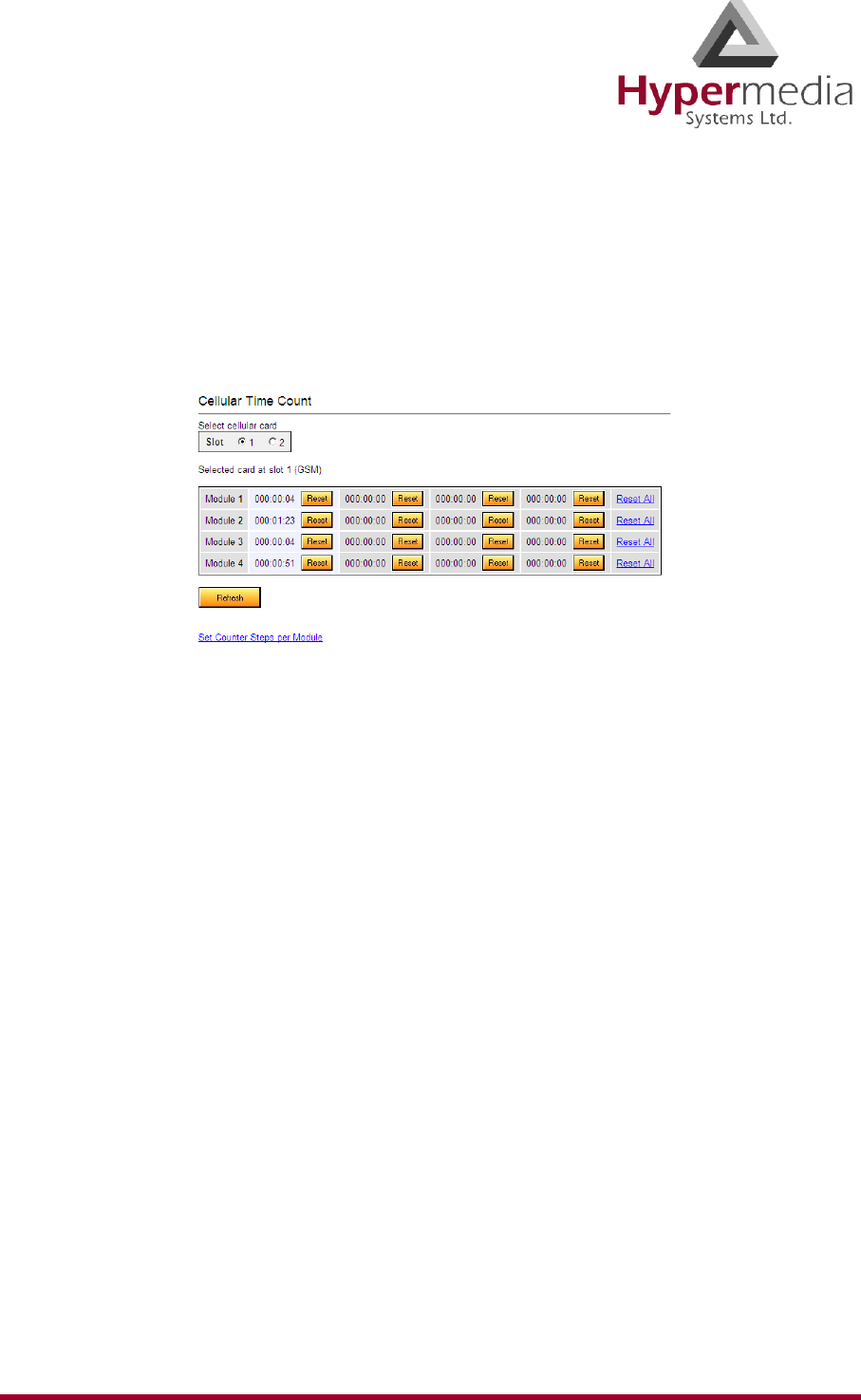
HMC Product Manual 46
Release 3.4: May 2010 SIM Counters
SIM Counters
Use the SIM Counter screen to review the actual usage time of each SIM card and to set
counter steps per module.
1. From the Cellular Cards branch of the HMC navigation pane, click the SIM Counters
sub-branch. The SIM Counters screen is displayed.
Figure 42: HMC SIM Counters Screen
2. If more than one slot is displayed, select a specific Cellular Card. The SIM Counters
screen of that cellular card is displayed.
3. Optionally, select from the following controls:
Reset
Resets the counter for the specific step.
Reset All
Resets all the counters in that module.
Refresh
Updates the information.
4. Optionally, click Set Counter Steps per Module to set the exact period of time per
counting step. The Cellular Card Call Counters Steps screen is displayed (see “Call
Counter Steps” on page 48).
Note: Setting Counter Steps is important when using the SIM Auto Manage with pre-paid
SIM cards.
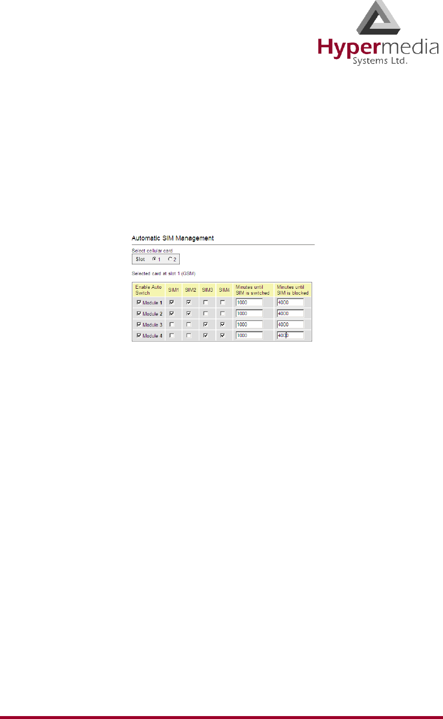
HMC Product Manual 47
Release 3.4: May 2010 SIM Auto Manage
SIM Auto Manage
Use the SIM Auto Manage screen to configure the Gateway to automatically alternate—and/or
discontinue—use of SIM cards. This enables load-balancing between a GSM module’s SIM
cards based on preconfigured switched time cycle.
To enable automatic management of SIM cards:
1. From the Cellular Cards branch of the HMC navigation pane, click the SIM Auto Man-
age sub-branch. The SIM Auto Manage screen is displayed.
Figure 43: HMC SIM Auto Manage Screen
2. If more than one slot is displayed, select a specific Cellular Card. The SIM Auto Manage
screen of that cellular card is displayed.
3. Select the checkbox beside a module number in the Enable Auto Switch column. The
SIM column checkboxes and Minutes column fields are displayed.
4. To assign a SIM card to a module, select the checkboxes in the SIM column.
Note: In Figure # 43, each module has two SIM cards assigned to it. The Gateway will allow
a SIM card to function for 1000 minutes and then switch to the second SIM card. Once
a SIM card has functioned for 4000 minutes—that is, 4 cycles—it is blocked. It can
only be unblocked manually.
5. In the Minutes until SIM is switched field, enter an amount of time measured in minutes.
This is the how long each SIM card will be used until the Gateway automatically switches
to the next SIM card assigned to that module.
6. In the Minutes until SIM is blocked field, enter an amount of time measured in minutes.
The is the totally amount of time a SIM card is used before the Gateway discontinues use
of it.
7. Click Apply Settings and wait for Configuration Saved to be displayed.
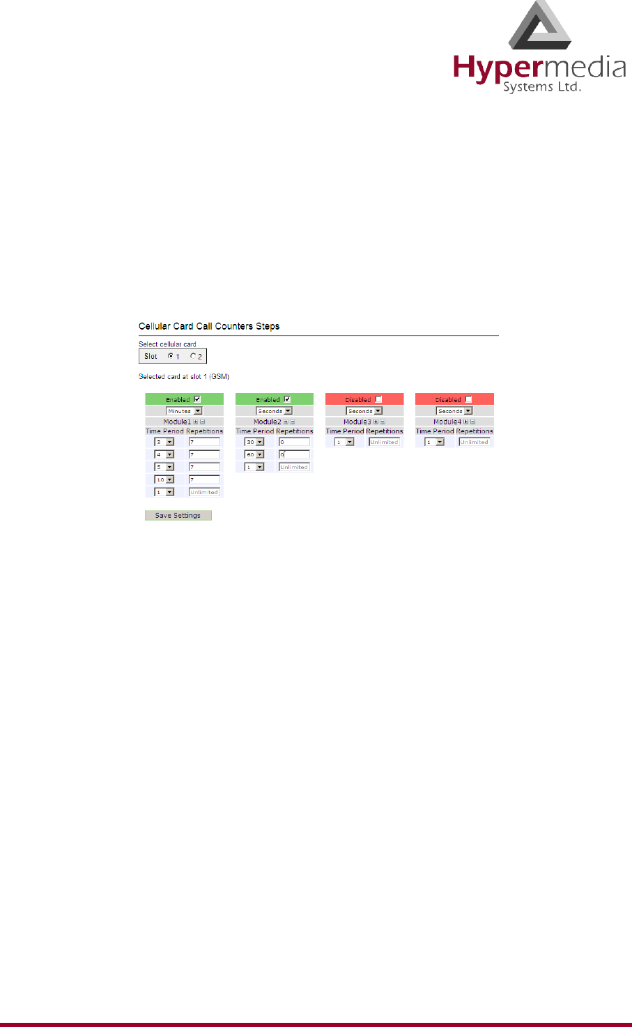
HMC Product Manual 48
Release 3.4: May 2010 Call Counter Steps
Call Counter Steps
Steps, Time Periods, and Repetitions work as follows: If the Time Period = 60 seconds and
Repetition = 3, and the caller speaks for 10 seconds, he will be charged for Time Period = 60
seconds. If the caller speaks for 110 seconds, he will be charged for Time Period = 120 sec-
onds. This charging policy—that is, step—expires after 180 seconds that being the Time
Period (= 60 seconds) times the Repetition (= 3). Then, the next step is applied. The final step
will always be 1 x Unlimited.
Figure 44: HMC Cellular Call Counter Steps Screen
To configure Counters Steps:
1. If more than one slot is displayed, select a specific Cellular Card. The SIM Counters
screen of that cellular card is displayed.
2. Select a checkbox to enable the step. When enabled, the area is displayed in the color
green.
3. From the upper dropdown menu, select either Seconds or Minutes. This determines the
duration of time indicated by the numbers in the Time Period column.
4. Increase the number of steps by clicking the plus sign beside the module number.
5. For each step, define the Time Period—that is, how long—the step is applied.
6. For each step, define the number of repetitions.
7. Repeat the procedure for additional modules.
8. Click Save Settings and wait for Configuration Saved to be displayed.
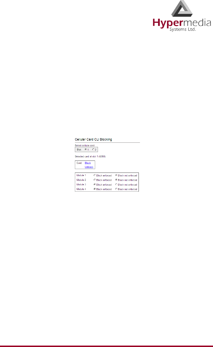
HMC Product Manual 49
Release 3.4: May 2010 CLI Blocking
CLI Blocking
Use the Calling Line Identification (CLI) Blocking screen to hide the caller’s phone number
from the person receiving the call.
Note: Some operators do not allow CLI Blocking. In some cases, if the CLI is blocked, the
call does not go through. Check the operator’s policy.
To block CLI:
1. From the Cellular Cards branch of the HMC navigation pane, click the CLI Blocking
sub-branch. The CLI Blocking screen is displayed.
Figure 45: HMC Cellular CLI Blocking Screen
2. If more than one slot is displayed, select a specific Cellular Card. The CLI Blocking
screen of that cellular card is displayed.
3. Use one of the two options:
Card
•Block
Click Block to block CLI for all 4 of a card’s SIM modules.
•Unblock
Click Unblock to allow CLI for all 4 of a card’s SIM modules.
Module
•Block enforced
Select Block enforced to block CLI for a specific SIM card.
•Block not enforced
Select Block not enforced to allow CLI for a specific SIM card.
4. Click Apply Settings and wait for Configuration Saved to be displayed.
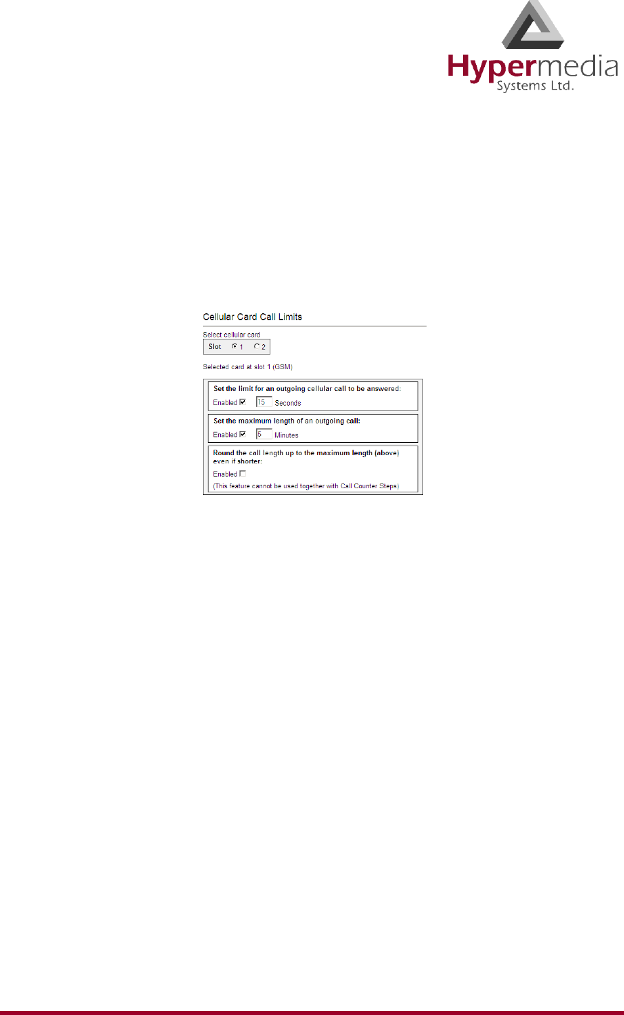
HMC Product Manual 50
Release 3.4: May 2010 Call Limits
Call Limits
Use the Call Limits screen to set the amount of time the Gateway will wait for an outgoing call
to be answered and to set the maximum length of outgoing call.
To set Call Limits:
1. From the Cellular Cards branch of the HMC navigation pane, click the Call Limits sub-
branch. The Call Limits the screen is displayed.
Figure 46: HMC Cellular Call Limits Screen
2. If more than one slot is displayed, select a specific Cellular Card. The Call Limits screen
of that cellular card is displayed.
3. Select or clear the following limits:
Set the limit for an outgoing cellular call to be answered
When enabled, enter a duration of time measured in seconds that the gateway will wait for
the call to be answered.
Set the maximum length of an outgoing call
When enabled, enter a duration of time measured in minutes that is the maximum
permitted length of a phone call. Calls are disconnected at the beginning of the last
minute, rather than its end.
Round the call length up to the maximum length
When enabled, callers are charged for the maximum length (defined above) even when the
conversation is shorter than the maximum length.
Note: Round the call up to the maximum length cannot be used with SIM Counters steps (see
“Call Counter Steps” on page 48).
4. Click Apply Settings and wait for Configuration Saved to be displayed.
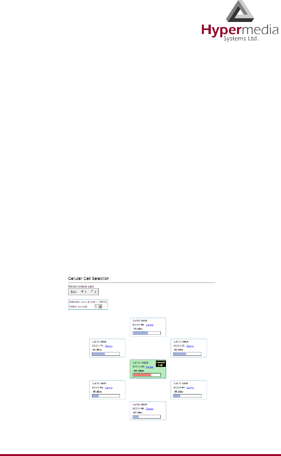
HMC Product Manual 51
Release 3.4: May 2010 Cell Selection
Cell Selection
Use the Cell Selection screen to manually camp on a cellular site. Most often, a user selects
the strongest cell site. However, if the Base Transceiver Station (BTS) or tower is locked, this
service cannot be applied.
Notes: What is Camp On? After completing the cell selection process a MS (Mobile Station)
or UE (User Equipment) will camp onto the cell that offers what seems to be the best
radio connection within the network.
What is BCCH? BCCH stands for Broadcast Control Channel. This downlink channel
contains specific parameters needed by a mobile in order that it can identify the
network and gain access to it. Typical information includes the LAC (Location Area
Code) and RAC (Routing Area Code), the MNC (Mobile Network Code) and BA
(BCCH Allocation) list.
dBm is an abbreviation for the power ratio in decibels (dB) of the measured power
referenced to one milliwatt (mW). It is used in radio and fiber optic networks as a
measure of absolute power because of its capability to express values in a short form.
This feature functions only with Wavecom GSM modules.
To camp on a site:
1. From the Cellular Cards branch of the HMC navigation pane, click the Cell Selection
sub-branch. The Cell Selection screen is displayed.
Figure 47: HMC Cellular Cell Selection Screen
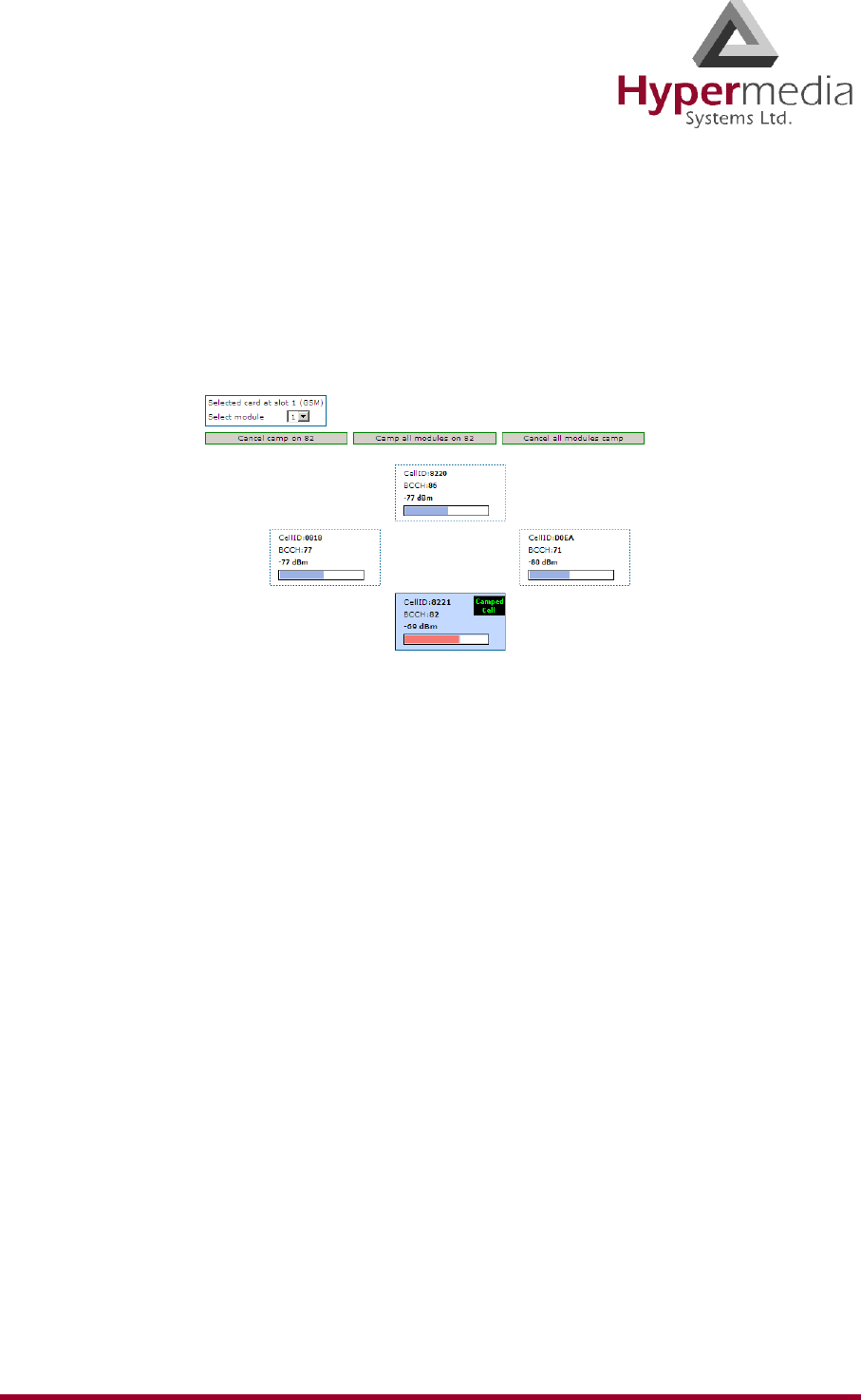
HMC Product Manual 52
Release 3.4: May 2010 Cell Selection
2. If more than one slot is displayed, select a specific Cellular Card. The Cell Selection
screen of that cellular card is displayed.
3. From the Select module dropdown box, select a module. This is the module that the
Camp selection will be applied to.
4. In one of the CellID boxes, click Camp. The screen indicates Camp Cell and new con-
trols are displayed at the top of the screen.
5. Optionally, to camp all the card’s modules on the same cell, click Camp all modules on.
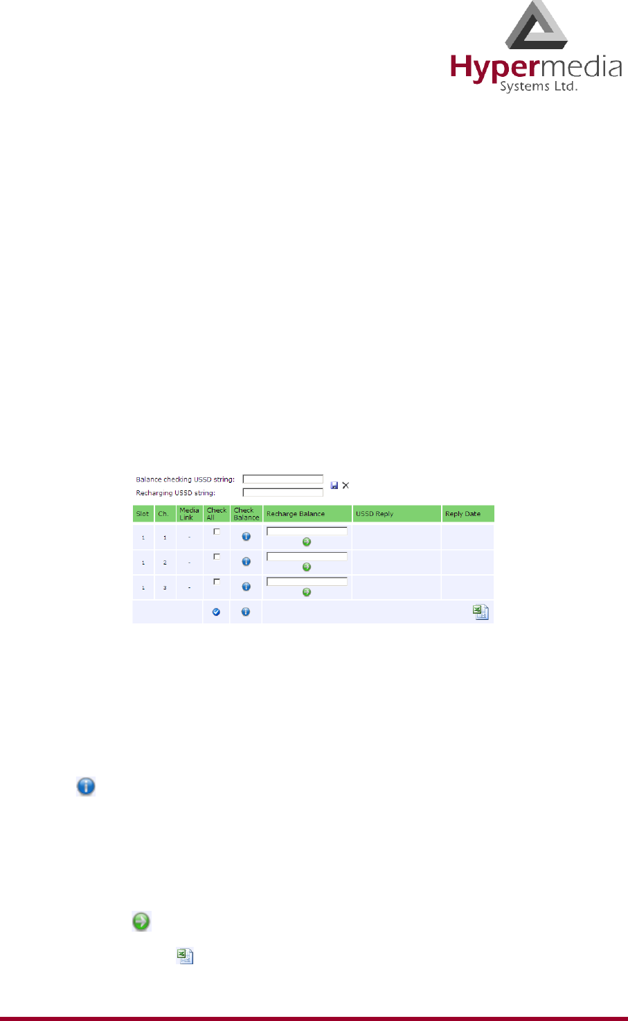
HMC Product Manual 53
Release 3.4: May 2010 USSD SIM Balance
USSD SIM Balance
Use the USSD SIM Balance screen to check the balance remaining on a SIM card and to add
value to (charge) a SIM card.
Note: Unstructured Supplementary Service Data is a standard for transmitting information
over GSM signalling channels. It is mostly used as a method to query the available
balance and other similar information in pre-paid GSM services. The function that is
triggered when sending USSD is network-dependent and depends on the specific
services the operator is offering. (Wikipedia)
1. Ensure that your Service Provider has given you a USSD string for checking balance and
a second string for adding value (charging) the SIM card.
2. From the Cellular Cards branch of the HMC navigation pane, click the USSD SIM Bal-
ance sub-branch. The USSD SIM Balance screen is displayed.
Figure 48: HMC Cellular USSD SIM Balance Screen
3. Enter the Balance checking USSD string.
4. Enter the Recharging USSD string.
5. Select or clear the Check All checkbox. When selected, the Hypermedia Management
Console will check the balance of all the SIM cards.
6. Click (Check Balance). The balance is displayed in the USSD Reply column.
7. Optionally, recharge the SIM card:
a. Ensure that you have a recharge string. Often, the string is displayed on recharge
cards after a removing a layer of ink that hides the string.
b. Enter the string into the Recharge Balance field.
c. Click the (Recharge Balance) button.
8. Optionally, click the (Microsoft Excel) icon to save the results as an Excel file.
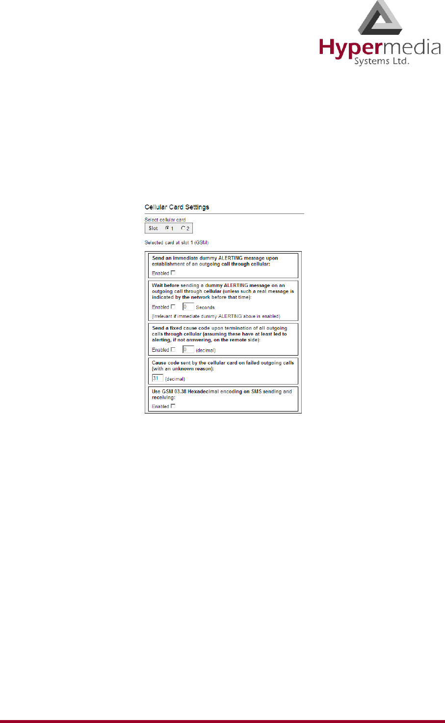
HMC Product Manual 54
Release 3.4: May 2010 Settings
Settings
Use the Settings screen to enable and disable advanced parameters. For assistance with these,
contact Technical Support.
1. From the Cellular Cards branch of the HMC navigation pane, click the Settings sub-
branch. The Cellular Card Settings screen is displayed.
Figure 49: HMC Cellular Card Settings Screen
2. If more than one slot is displayed, select a specific Cellular Card. The Cellular Card Set-
tings screen of that cellular card is displayed.
3. Click Apply Settings and wait for Configuration Saved to be displayed.
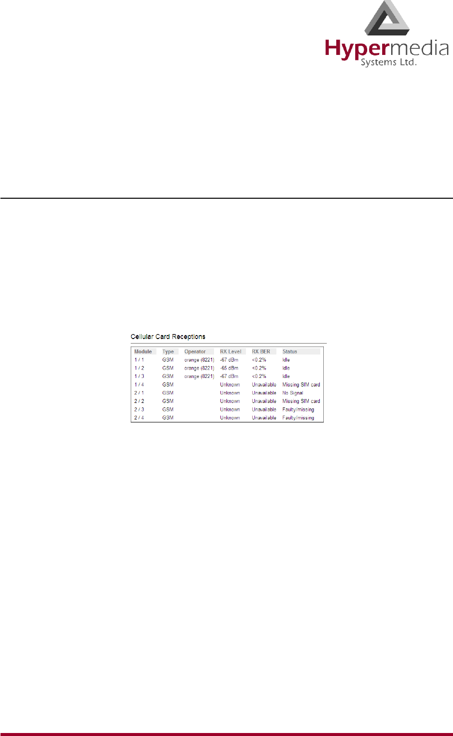
HMC Product Manual 55
Release 3.4: May 2010 Monitoring Cellular Cards
Monitoring Cellular Cards
To monitor the cellular cards, open the Monitor > Cellular branch of the Hypermedia Manage-
ment Console. There are three views.
All Cells
To view information about all the SIM slots on all the cellular modules, expand the Monitor >
Cellular Cards sub-branch and select All Cells. The Cellular Cards Reception screen is dis-
played.
Note: The status of a SIM slot is displayed here and on the Status screen, but not on the
Reception screen.
Figure 50: Cellular Cards Reception Screen
The screen displays the following information:
Module
This indicates the card and the SIM slot number.
Type
The module can support either GSM or CDMA.
Operator
This is the cellular network associated with the SIM card and the Cell ID.
RX Level
This indicates the received power level in dBm. This number can be between –51 dBm
and –110 dBm (see “RX Level” on page 56).
RX BER
Bit Error Rate (BER) is a calculated figure for the quality of the signal received from the
base (see “RX BER” on page 56).
Status
This displays the status of the specific SIM slot.
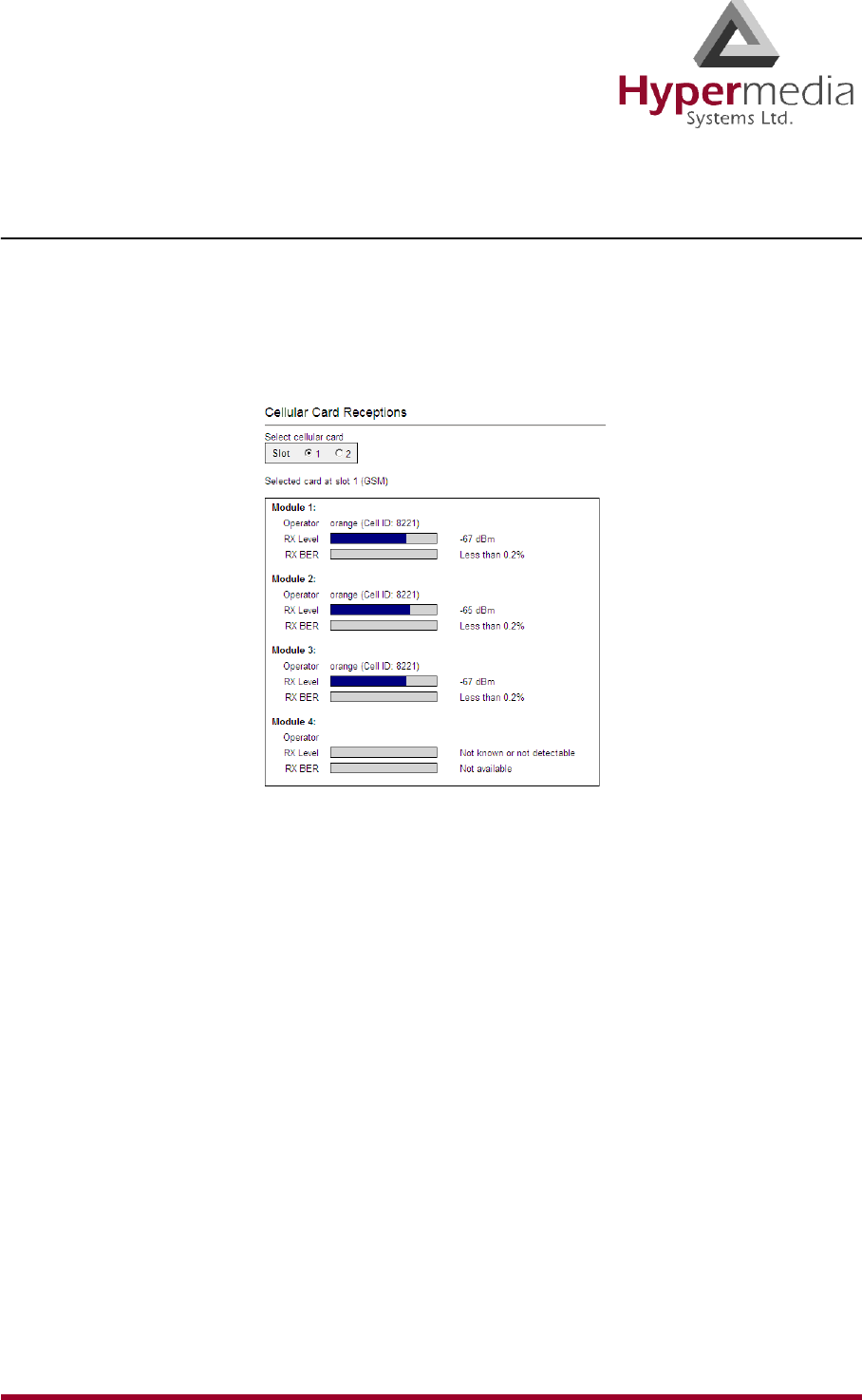
HMC Product Manual 56
Release 3.4: May 2010 Monitoring Cellular Cards
Reception
To view information about the SIM slots on a specific cellular modules, especially the recep-
tion level and the BER level:
1. Expand the Monitor > Cellular Cards sub-branch and select Reception.
2. Select a specific slot. The Cellular Cards Reception screen for that card is displayed.
Figure 51: Specific Card’s Cellular Reception Screen
The screen displays the following information:
Type
This information is displayed between the Slot selection box and the reception
information. A module can support either GSM or CDMA.
Module 1 / 2 / 3 / 4
This indicates the card’s SIM slot number.
Operator
This is the cellular network associated with the SIM card and the Cell ID.
RX Level
This indicates the received power level in dBm. This number can be between –51 dBm
and –110 dBm.
RX BER
Bit Error Rate (BER) is a calculated figure for the quality of the signal received from the
base. It is an indication of the number of errors detected in the signal received by the
cellular channel, graded into quality ratings according to the percentage of errors in the
data. Typical values for BER are between “Not Available” (which represents less than
0.2%) and 6.4%.
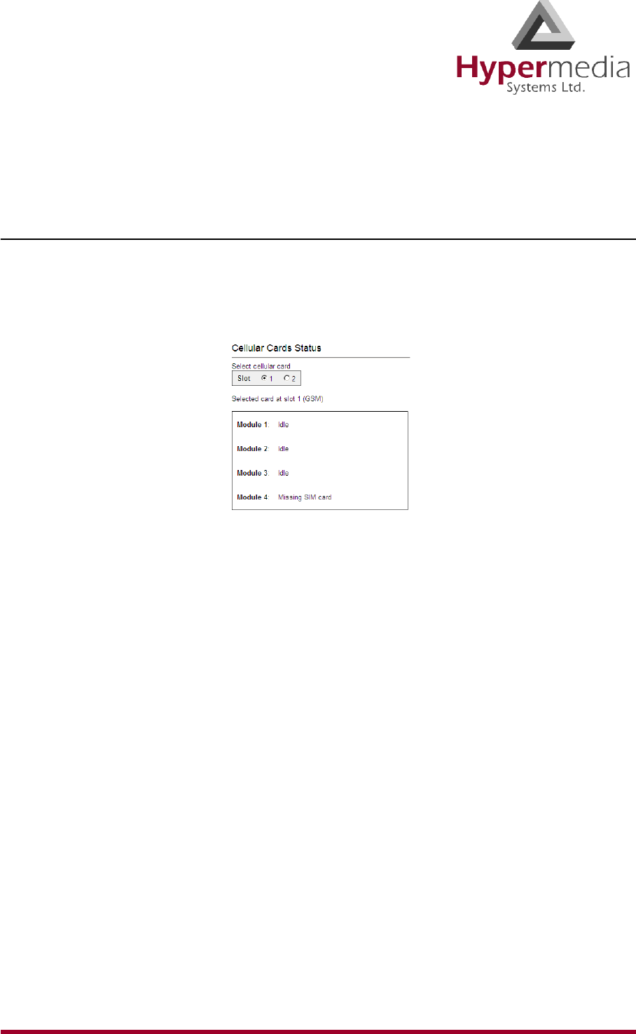
HMC Product Manual 57
Release 3.4: May 2010 Monitoring Cellular Cards
BER of more than 6.4 will result in calls being disconnected as well as “noisy” calls. If
this occurs, find a better location for the antenna or check the connections to the antenna.
Status
To view information about the status of SIM slots on a specific cellular module:
1. Expand the Monitor > Cellular Cards sub-branch and select Status.
2. Select a specific slot. The Cellular Cards Status screen for that card is displayed.
Figure 52: Cellular Cards Status Screen
3. Review the status. Common possibilities include:
• Module doesn’t exist or is faulty
• Idle
• Incoming call from cellular network
• Remote side ringing
• Call connected
• Call cleared
• Dialing out through cellular network
• No Signal
• Missing SIM card

HMC Product Manual 58
Release 3.4: May 2010 Monitoring Cellular Cards
This page is intentionally blank.
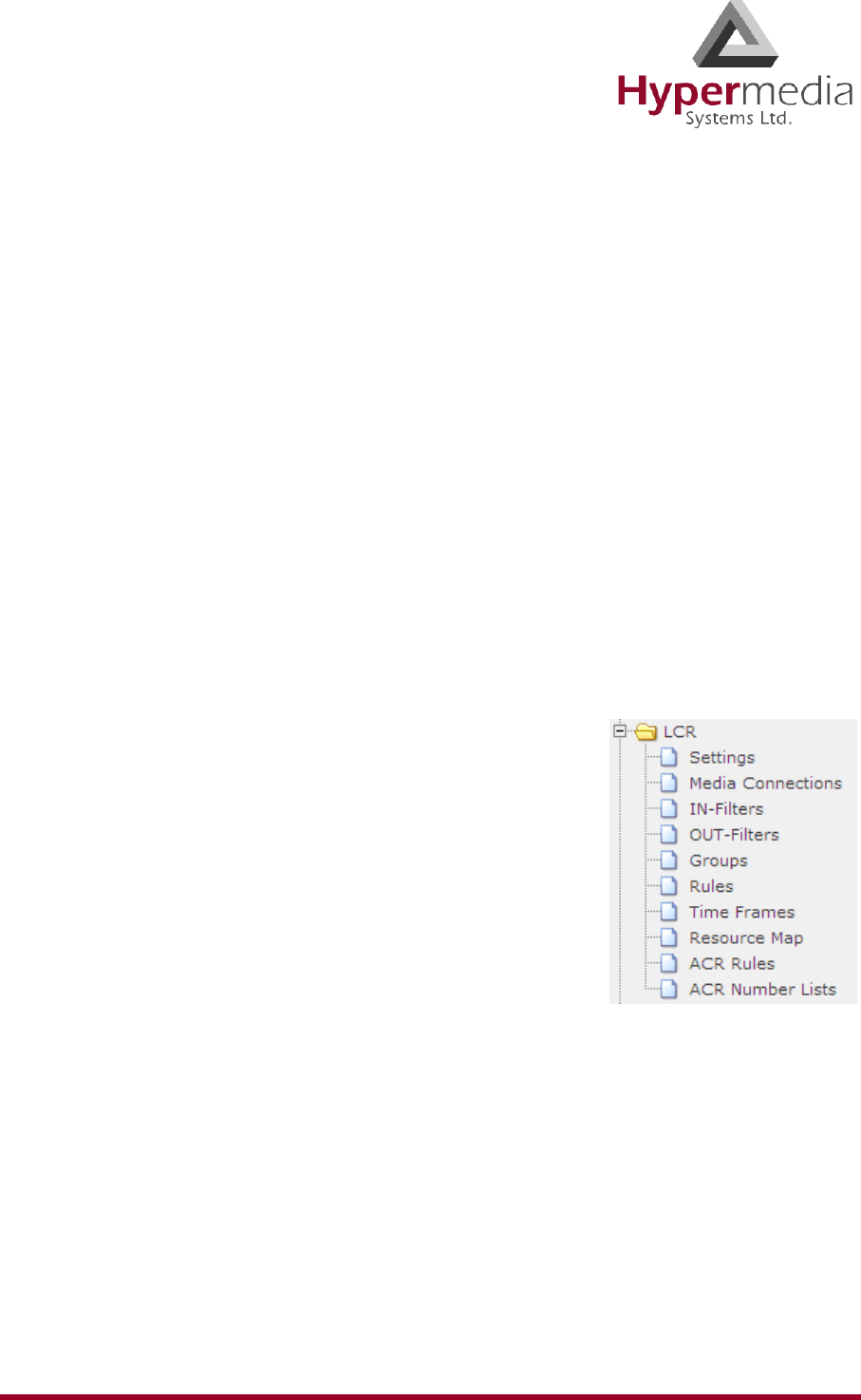
HMC Product Manual 59
Release 3.4: May 2010
Chapter 4
CONFIGURING LCR
Note: The Hypermedia Management Console is customized to match the specific order.
Some branches of the HMC may or may not appear based upon the customization.
This section includes:
• “Overview” on page 60
• “Linking to LCR” on page 61
• “Groups” on page 66
• “Resource Map” on page 68
• “Rules” on page 72
• “Filters” on page 75
• “Time Frames” on page 76
• “Advanced Call Routing (ACR)” on page 78
• “Callthrough” on page 83
• “Number Filters” on page 85
• “Callback Triggers” on page 88
• “CDR” on page 90
• “Activating LCR in PC Cards” on page 94
• “LCR CDRs” on page 96

HMC Product Manual 60
Release 3.4: May 2010 Overview
Overview
Gateways with Least Cost Routing (LCR) route calls based on rules created by the adminis-
trator. This results in per-call routing. In contrast, when using gateways without LCR, all call
routes are fixed.
LCR enables greater customizing and, potentially, saves money.
The best-practice order of building the LCR plan is:
Note: A best-practice is a technique or methodology that, through experience and research,
has been proven to efficiently and reliably lead to the desired result.
1. Link media to the LCR module
2. Create Groups
3. Assign the LCR Resources to Groups
4. Create Rules
The following are optional:
• Create IN or OUT filters
• Create Time Frames and apply them to the Rules
This section follows the best-practice order.
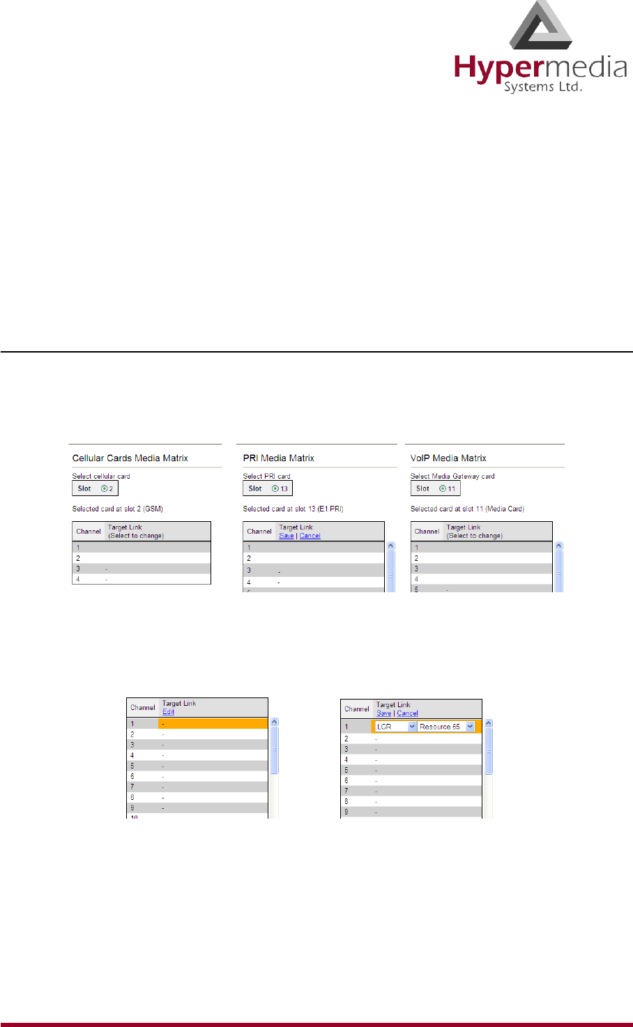
HMC Product Manual 61
Release 3.4: May 2010 Linking to LCR
Linking to LCR
Each media type must be configured to refer calls to the LCR module. This can be done either
from the specific media branch or from the LCR branch.
Note: Each of the three media type branches—Cellular, PRI, and VoIP—includes a sub-
branch named Media Connections.
Linking from a Media Branch
To link a media to LCR:
1. From the HMC navigation pane, click a Media Connections sub-branch. The Media
Matrix is displayed.
Figure 53: Media Matrix before LCR
2. Click within a channel row. The row turns yellow.
3. Click Edit. The row becomes configurable.
Figure 54: Channel Row when Configurable
4. From the dropdown lists, select LCR and the Resource number.
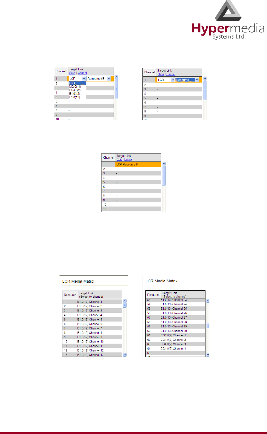
HMC Product Manual 62
Release 3.4: May 2010 Linking to LCR
Figure 55: Channel Row Dropdown Lists
5. Click Save. The configuration dropdown boxes are hidden.
Figure 56: Channel Row Configured
6. Optionally, repeat the process for additional channels and other media types.
7. Click Apply Settings and wait for Configuration Saved to be displayed.
8. When finished, from the LCR branch, select Media Connections. The LCR Media
Matrix displays the links.
Figure 57: Two Views of the LCR Media Matrix Display
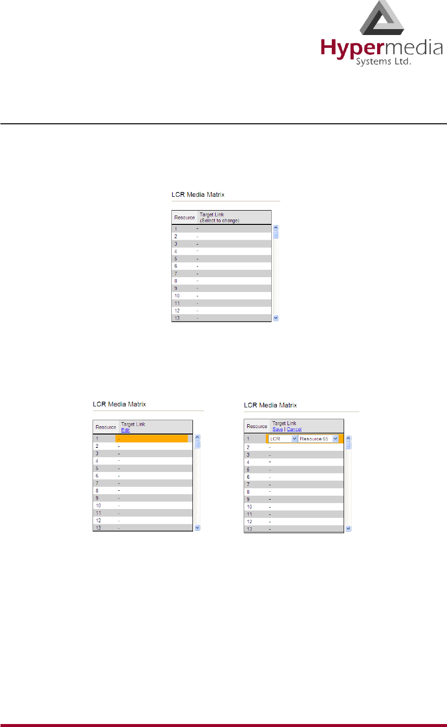
HMC Product Manual 63
Release 3.4: May 2010 Linking to LCR
Linking from the LCR Branch
To link a media to LCR:
1. From the HMC navigation pane’s LCR branch, click the Media Connections sub-branch.
The LCR Media Matrix is displayed.
Figure 58: LCR Media Matrix
2. Click within a Resource row. The row turns yellow.
3. Click Edit. The row becomes configurable.
Figure 59: LCR Row when Configurable
4. From the dropdown menus, select the media and the Resource number.
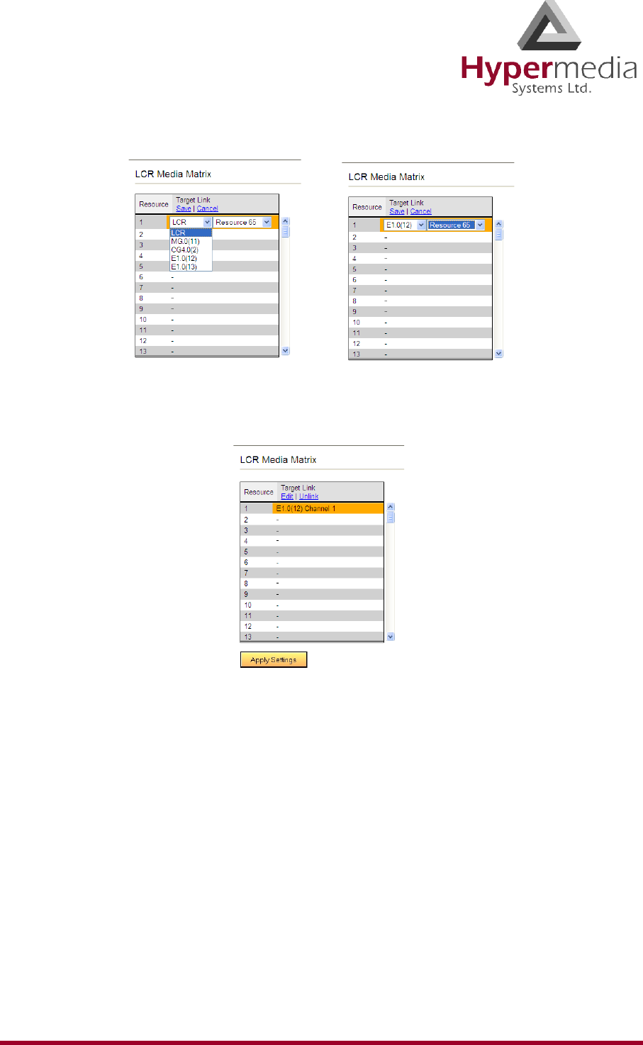
HMC Product Manual 64
Release 3.4: May 2010 Linking to LCR
Figure 60: LCR Row Dropdown Lists
5. Click Save. The configuration dropdown boxes are hidden.
Figure 61: LCR Row Configured
6. Click Apply Settings and wait for Configuration Saved to be displayed.
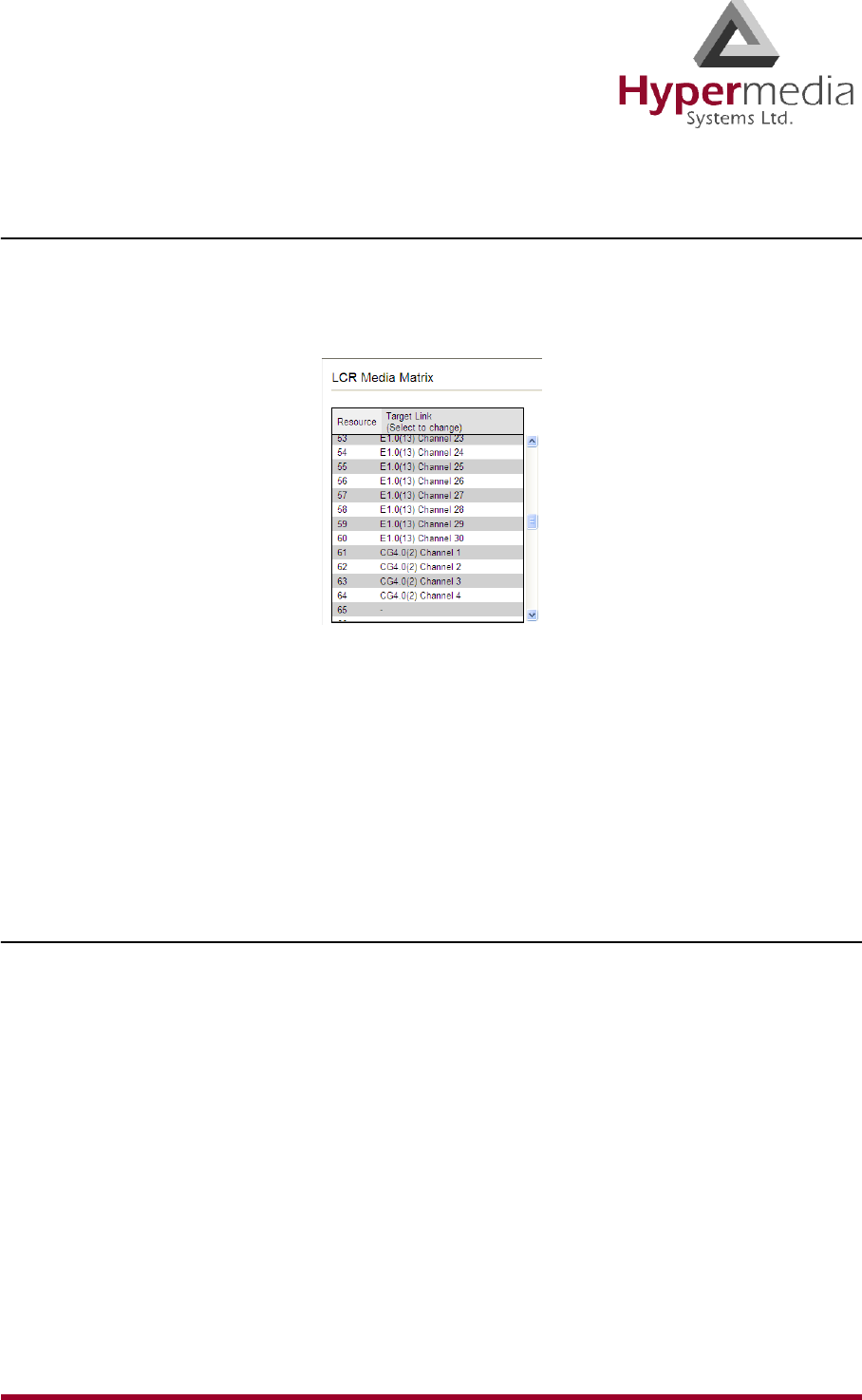
HMC Product Manual 65
Release 3.4: May 2010 Linking to LCR
Editing a Target Link
To edit a link:
1. From the HMC navigation pane’s LCR branch, click the Media Connections sub-branch.
The LCR Media Matrix is displayed.
Figure 62: LCR Media Matrix
2. Click within a Resource row. The row turns yellow.
3. Click Edit. The row becomes configurable.
4. From the dropdown menus, edit the settings.
5. Click Save. The configuration dropdown boxes are hidden.
6. Click Apply Settings and wait for Configuration Saved to be displayed.
Breaking a Link (Unlink)
To break a link:
1. From the HMC navigation pane’s LCR branch, click the Media Connections sub-branch.
The LCR Media Matrix is displayed.
2. Click within a Resource row. The row turns yellow.
3. Click Unlink. The settings disappear.
4. Click Apply Settings and wait for Configuration Saved to be displayed.
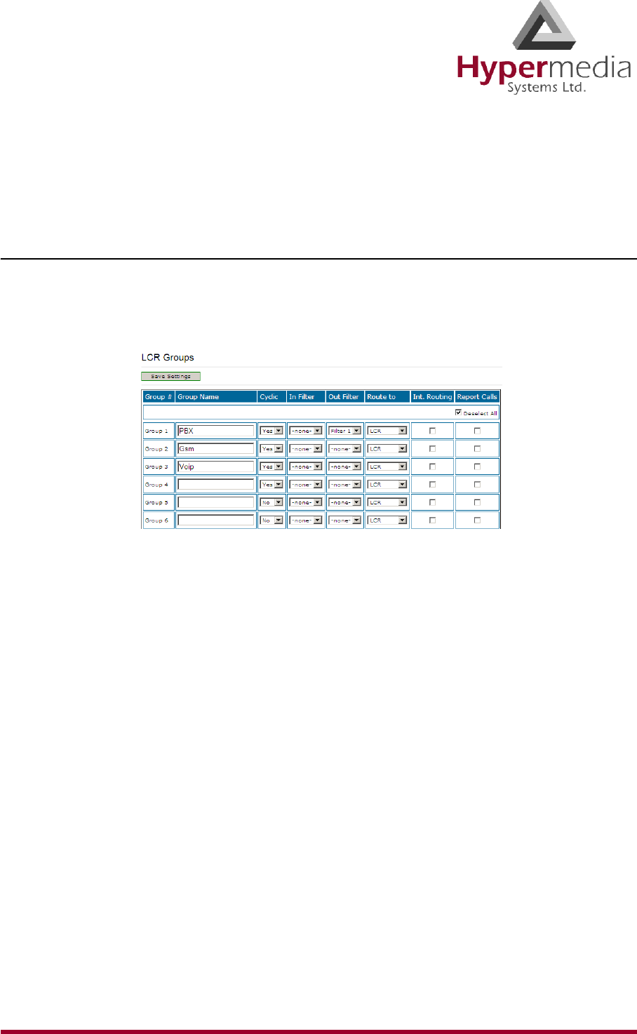
HMC Product Manual 66
Release 3.4: May 2010 Groups
Groups
Creating Groups simplifies consistent application of LCR strategies.
Creating a Group
To create a group:
1. From the HMC navigation pane’s LCR branch, click the Groups sub-branch. The Groups
screen is displayed.
Figure 63: LCR Groups Screen
2. Name the Group. Since the Group name appears in other places, we recommend using an
identifiable name.
3. In the Cyclic column dropdown menu, define whether or not the Group will be cyclic.
Yes
The LCR module begins searching for an available channel from the last used channel.
No
The LCR module begins searching for an available channel from the first channel in that
group.
4. Optionally, and if already defined, from the In Filter dropdown menu, select an In Filter.
See “Filters” on page 75.
5. Optionally, and if already defined, from the Out Filter dropdown menu, select an Out
Filter. See “Filters” on page 75.
6. From the Route to Group dropdown menu, define whether or not calls arriving to that
Group will be rerouted to a specific Group.
none
The LCR Rules are applied before the call is routed to a specific channel.
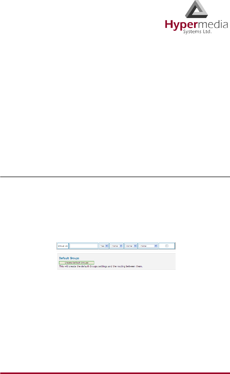
HMC Product Manual 67
Release 3.4: May 2010 Groups
< Specific Group Name >
All calls coming from Resources assigned to this Group are rerouted to the selected
Group. The LCR rules are not analyzed for calls entering the LCR module from this
group.
7. Select or clear the Int. Routing checkbox. When selected, all outgoing calls through the
group are logged. The logs are then checked to determine the destination number for an
incoming calls. If a match is found, the original destination number is ignored.
8. Select or clear the Report Calls checkbox. When selected, calls are sent to an external
Hypermedia application for billing.
Note: To purchase the billing application, contact Hypermedia.
9. Click Save Settings.
Using the Default Group Settings
The HMC includes pre-defined Group settings. These can be used instead of customized set-
tings.
To apply the default Group settings:
1. From the HMC navigation pane’s LCR branch, click the Groups sub-branch. The Groups
screen is displayed.
2. Scroll to the bottom of the screen. The Create Default Groups button appears within the
Default Groups prompt.
Figure 64: Create Default Groups Button
3. Click Create Default Groups.
4. Scroll to the top of the page.
5. Click Save Settings.
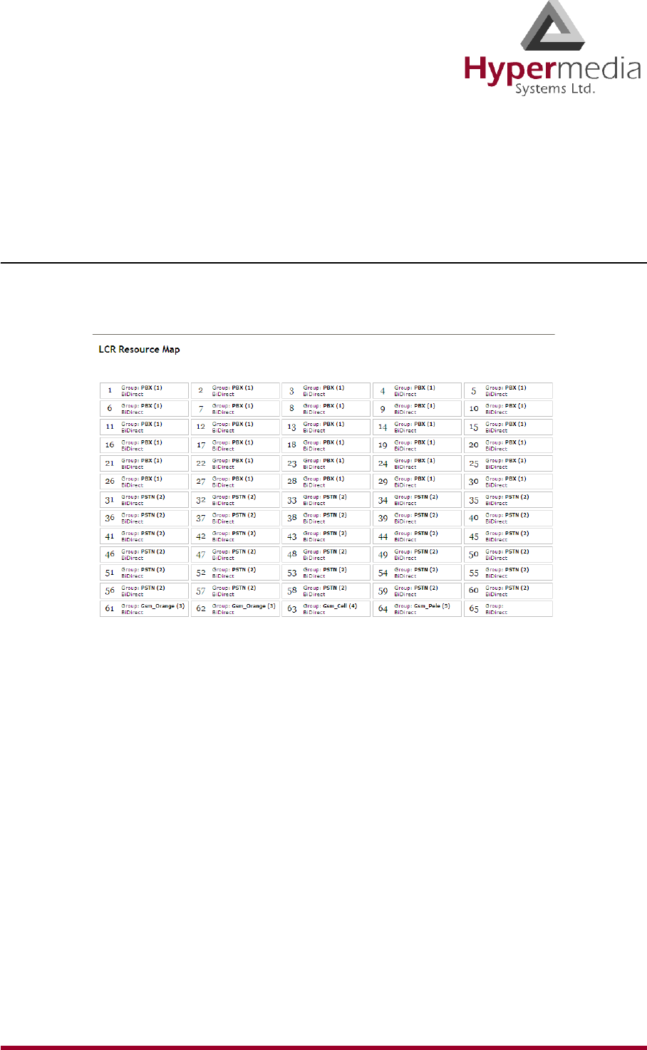
HMC Product Manual 68
Release 3.4: May 2010 Resource Map
Resource Map
Use the LCR Resource Map to assign Resources to Groups.
Sample Assignment
The picture below illustrates Resource assignment. The first 30 Resources are assigned to the
PBX, the second 30 are assigned to the PSTN, and the final 4 are assigned to Cellular.
Figure 65: Sample Resource Assignment
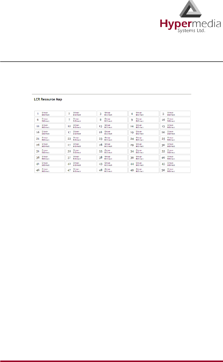
HMC Product Manual 69
Release 3.4: May 2010 Resource Map
Assigning LCR Resources
To assign LCR Resources to Groups:
1. From the HMC navigation pane’s LCR branch, click the Resource Map sub-branch. The
Resource Map screen is displayed.
Figure 66: LCR Resource Map Before Assignments
2. Click a cell to select it. To select many cells, hold down the Shift key and click a cell else-
where on the map. The selected cells are shaded blue and the Set Group and Set Resource
Type dropdown lists appear near the top of the screen.
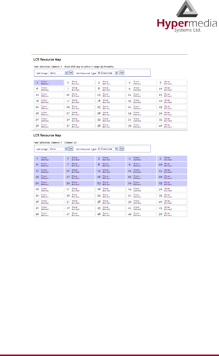
HMC Product Manual 70
Release 3.4: May 2010 Resource Map
Figure 67: Selecting LCR Resources
3. From the Select Group dropdown list, select a Group. This is the Group the shaded cells
will be associated with.
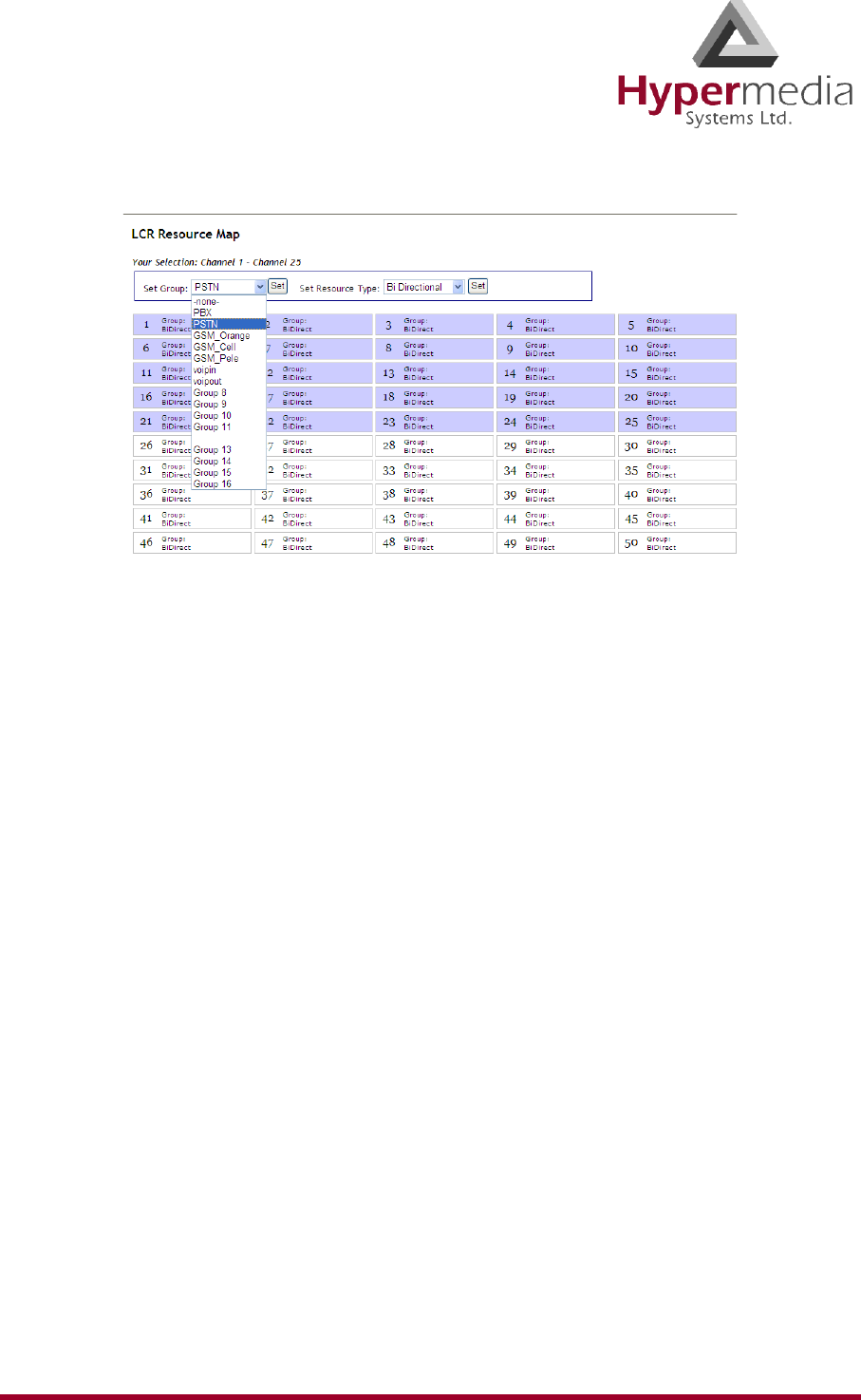
HMC Product Manual 71
Release 3.4: May 2010 Resource Map
Figure 68: Group Dropdown List
4. Click Set. The assignment is applied and saved.
5. From the Resource Type dropdown list, select either:
Bi Directional
This Resource can be used for both incoming calls and for outbound calls.
Outbound Only
This Resource can only be used for outbound calls.
6. Click Set. This completes the procedure.
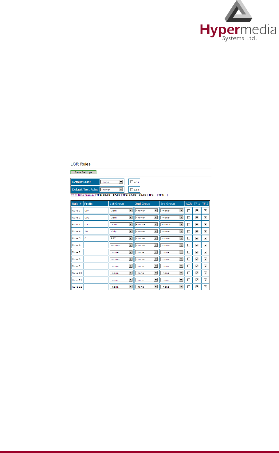
HMC Product Manual 72
Release 3.4: May 2010 Rules
Rules
Rules determine to which Group a call is routed. When Time Frames are not used, the Rule is
applied continuously. See “Time Frames” on page 76.
Creating a Rule
To create a Rule:
1. From the HMC navigation pane’s LCR branch, click the Rules sub-branch. The Rules
screen is displayed.
Figure 69: LCR Rules Screen
2. Place the cursor in an empty Rule # Prefix cell.
3. Enter the Prefix, that is, the first numbers of the destination number. The Prefix is often
the first numbers of a mobile phone service provider.
4. Configure the following:
1st Group
From the dropdown list, select the Group to which the LCR module will first route calls
with this prefix.
2nd / 3rd Group
Optionally, enter a second and third choice for where the call should be routed. These
choices are used when the 1st Group’s Resources are busy.

HMC Product Manual 73
Release 3.4: May 2010 Rules
ACR
When this checkbox is selected, the gateway redirects the call to a database containing
Advanced Call Routing lists. The call is routed according to rules on an external
application with advanced routing options.
Note: The number of TF columns is determined by the number of Time Frames defined.
TF1 / TF2
Select or clear the Time Frame checkboxes. When selected, the Time Frame is applied to
the Rule.
5. Optionally, repeats steps 2 until 4 for additional rules.
6. Ensure that the Rules are in the correct order. Rules are applied from top to bottom.
Therefore, place a Rule with a prefix identical to but shorter than another Rule’s prefix
after the longer Rule.
For example, if Rule 1’s prefix is 082 and Rule 2’s prefix is 08, calls beginning with 082
will be routed according to Rule 1 and all other calls beginning with 08 will be routed
according to Rule 2. If Rule 2 is placed above, the 082 calls will also be routed according
to it and the 082 Rule will be rendered ineffective.
7. Optionally, select a Default Rule.
WARNING! Do not confuse this Default Rule with the Default Rule Wizard at the bottom
of the screen. For an explanation of the second Default Rule Wizard, see “Creating a
Default Set of Rules” on page 74.
This rule is applied when a call’s prefix does not match one of the defined prefixes. Time
Frames are not applied to the Default Rule.
a. From the dropdown list, select a rule.
b. Select or clear the ACR checkbox. When selected, the gateway redirects the call to a
database containing Advanced Call Routing lists. The call is routed according to
rules on an external application with advanced routing options.
8. Disregard the Default Text Rule. For more information, contact Technical Support.
9. Click Save Settings.
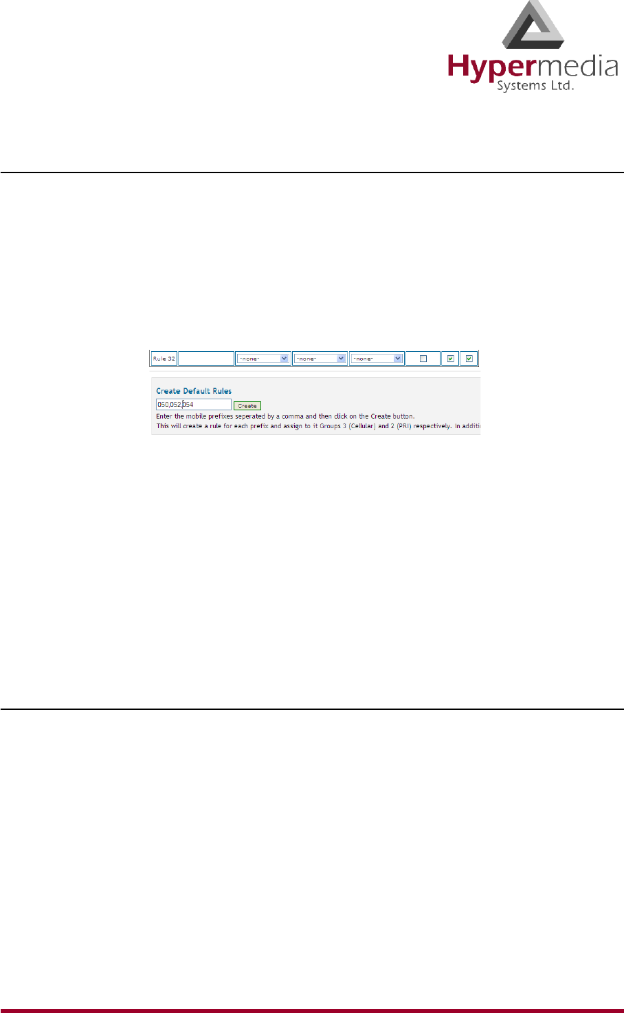
HMC Product Manual 74
Release 3.4: May 2010 Rules
Creating a Default Set of Rules
The HMC includes a Wizard for defining a set of simple Rules. These can be used instead of
customized Rules.
To use the Default Rules Wizard:
1. From the HMC navigation pane’s LCR branch, click the Rules sub-branch. The Rules
screen is displayed.
2. Scroll to the bottom of the screen. The Create button appears within the Create Default
Rules prompt.
Figure 70: Create Default Rules Button
3. Enter the first numbers (prefixes) of phone numbers used by mobile service providers.
Note: Separate prefixes with a comma. Do not add spaces.
4. Click Create.
5. Scroll to the top of the page.
6. Click Save Settings.
Deleting a Rule
To delete a Rule:
1. From the HMC navigation pane’s LCR branch, click the Rules sub-branch. The Rules
screen is displayed.
2. Place the cursor in the Prefix cell on the Rule’s row.
3. Delete the entry.
4. Click Save Settings.
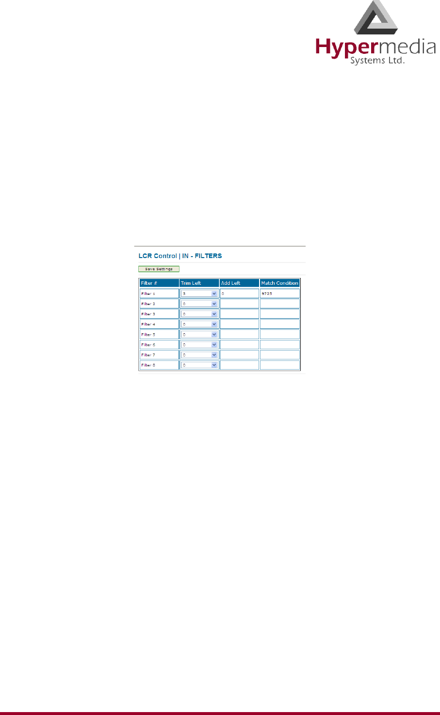
HMC Product Manual 75
Release 3.4: May 2010 Filters
Filters
Filters enable consistent, automatic management of phone numbers before they are routed.
An IN filter changes the destination number before the list of rules is processed. An OUT filter
changes the destination number after the list of rules has been processed and the destination
group has been chosen. The process is identical for both.
To create a Filter:
1. From the HMC navigation pane’s LCR branch, click either the IN or OUT Filters sub-
branch. The Filters screen is displayed.
Figure 71: LCR Filters Screen
2. Configure the following for up to eight filters:
Trim Left
From the dropdown menu, select the quantity of numbers that will be deleted from the
beginning of the destination number.
Add Left
Enter the number or numbers that will be added to the beginning of the destination
number.
Match Condition
Enter the exact numbers appearing in the incoming calls that this filter will be applied to.
“Condition” means the numbers appearing at the beginning of the phone number. This
filter will be applied to phone numbers with exactly those numbers.
3. Click Save Settings.
4. From the HMC navigation pane’s LCR branch, click the Groups sub-branch. The Groups
screen is displayed.
5. Optionally, from a Group’s In Filter dropdown menu, select an In Filter. The IN filter
will be applied to calls entering the LCR module from one of the system’s interfaces.
6. Optionally, from a Group’s Out Filter dropdown menu, select an Out Filter. The OUT
filter will be applied to calls exiting the LCR module to one of the system's interfaces.
7. Click Save Settings.
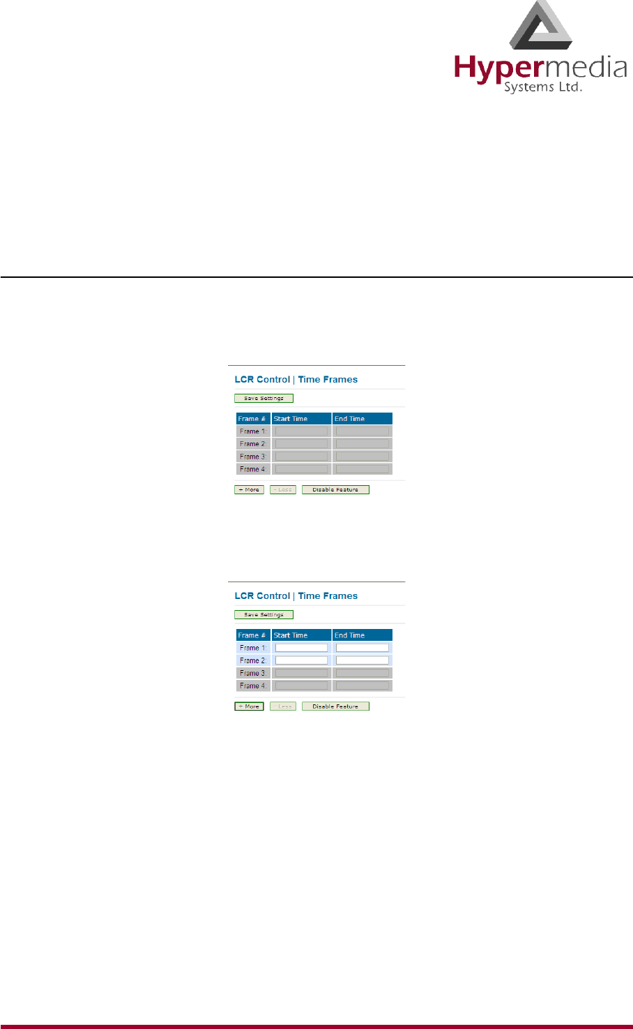
HMC Product Manual 76
Release 3.4: May 2010 Time Frames
Time Frames
The Time Frame determines the hours of the day when a Rule is applied. When Time Frames
are not used, the Rule is applied continuously.
Creating a Time Frame
To create a Time Frame:
1. From the HMC navigation pane’s LCR branch, click the Time Frames sub-branch. The
Time Frames screen is displayed. All four rows are gray.
Figure 72: LCR Time Frames Screen
2. Click More. Two rows are enabled.
Figure 73: Time Frame Rows when Configurable
3. In the Frame 1: Start Time cell, enter the time of day the first Time Frame will begin.
Disregard the Frame 1: End Time cell.
4. In the Frame 2: Start Time cell, enter the time of day the second Time Frame will begin.
Set the cursor in the End Time cell and the Frame 1 and Frame 2: End Time cells display
the alternate times.
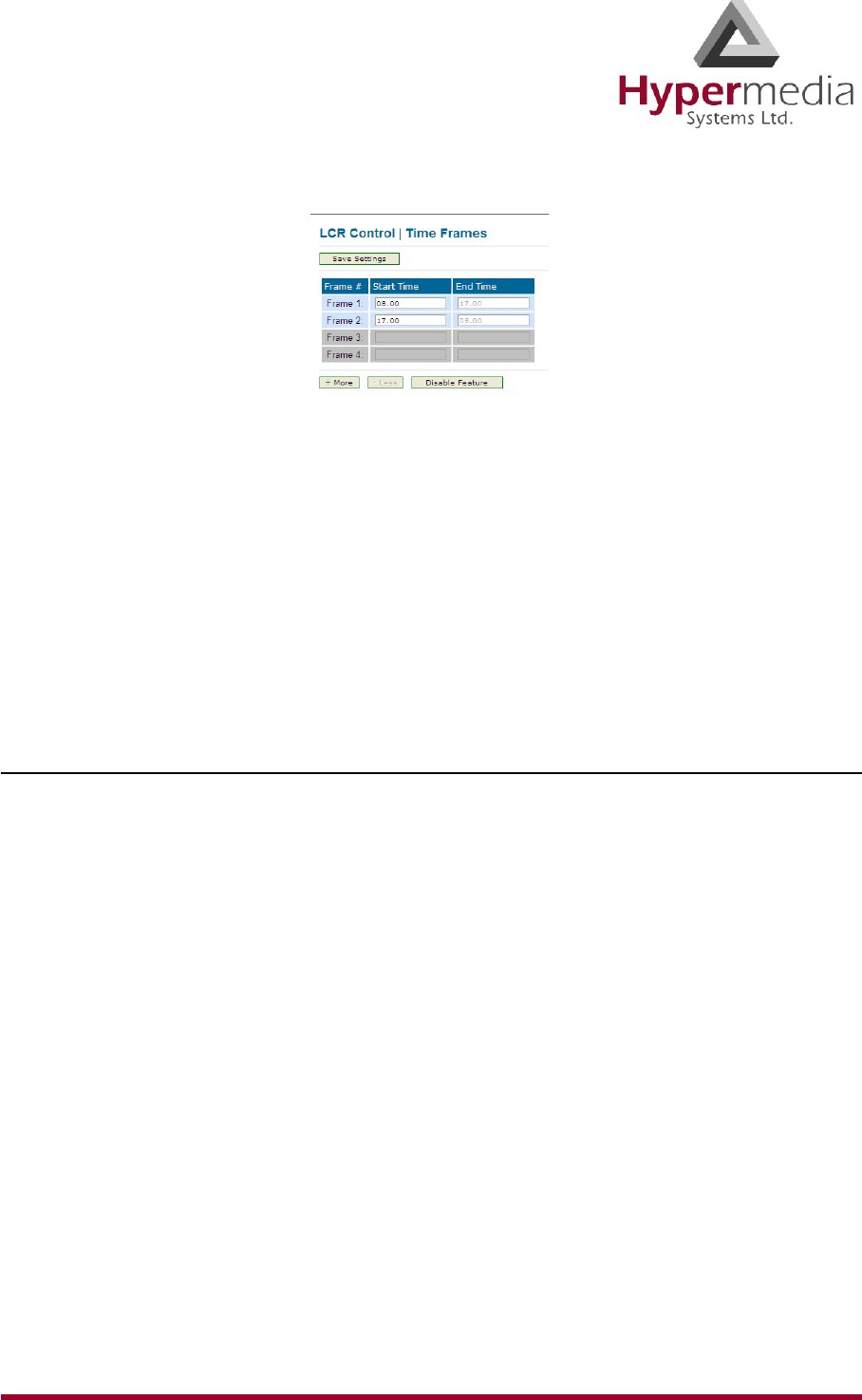
HMC Product Manual 77
Release 3.4: May 2010 Time Frames
Figure 74: End Time Displayed Automatically
Note: To erase all the entries and start over, or to disable use of Time Frames, click Disable
Feature.
5. Optionally, to add additional Time Frames, click More and enter the Start Time.
6. Click Save Settings.
Disabling Time Frames
To disable the Time Frames feature:
1. From the HMC navigation pane’s LCR branch, click the Time Frames sub-branch. The
Time Frames screen is displayed.
2. Click Disable Feature. All Time Frame definitions are erased.
3. Click Save Settings.
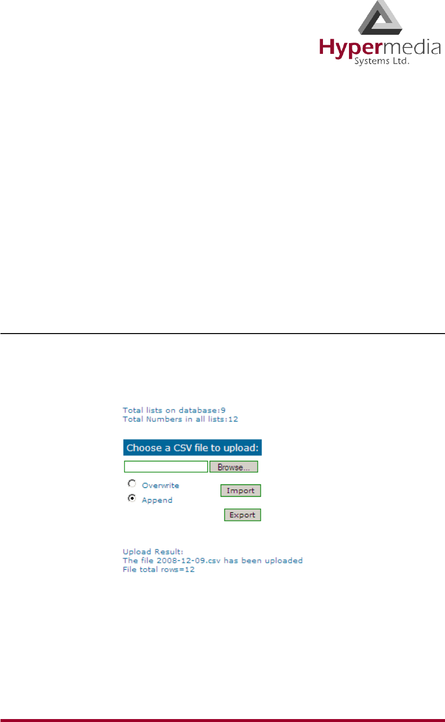
HMC Product Manual 78
Release 3.4: May 2010 Advanced Call Routing (ACR)
Advanced Call Routing (ACR)
Use ACR to define, for example, white lists and black lists. ACR supplements the LCR rules
created on the Rules screen.
Note: A white list includes the phone numbers that are authorized to use LCR whereas a
black list includes the phone numbers that are prevented from using the LCR.
Enabling ACR requires the following three steps:
a. Prepare and upload the Number List.
b. Define the ACR rules.
c. Enable a specific rule, or the default ACR rule, on the LCR Rules screen.
Modifying the Existing ACR Number List
To modify the existing ACR Number List:
1. From the HMC navigation pane’s LCR branch, click the ACR Numbers Lists sub-
branch. The ACR Number Lists screen is displayed.
Figure 75: ACR Number Lists Screen
2. Click Export. The standard Windows browse dialog box is displayed.
3. Save the .csv file.
4. Open the file in a text-editor, such as Notepad.
5. Modify the file. Preserve the format, that is, the words tag,number must appear as the
first row of the list.

HMC Product Manual 79
Release 3.4: May 2010 Advanced Call Routing (ACR)
6. Save and close the file.
7. On the ACR Number Lists Screen, click Browse. The standard Windows browse dialog
box is displayed.
8. Locate the .csv file containing the lists. Select it and click Open. The path to the .csv file
is displayed on the Number Lists Screen.
9. Select either:
Overwrite
When selected, the old .csv file is deleted and the new file replaces it.
Append
When selected, the entries on the new .csv file are added to the entries on the old .csv file.
10. Click Import. The report of total lists and total numbers is automatically updated.
Creating a New ACR Number List File
To define a number list:
1. Create a new file whose file-name ends with the extension .csv.
2. Open the file in a text-editor, such as Notepad.
3. Enter the words tag,number as the first row of the list.
Note: In step 4, the term “list” indicates all entries that are share the same tag.
4. Add the tag and number of each entry. Ensure that a comma separates the tag and number.
The following example includes 5 lists:
tag,number
XYZ,0774445004
XYZ,0509080704
XYZ,0523030303
ABC,0509380137
ABC,0509380136
CLCOM,052
PHONE,054
CELLC,050
WARNING! A comma must separate the tag and the number or the list will not register
properly.
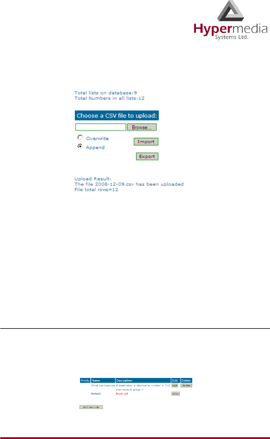
HMC Product Manual 80
Release 3.4: May 2010 Advanced Call Routing (ACR)
5. From the HMC navigation pane’s LCR branch, click the ACR Numbers Lists sub-
branch. The ACR Number Lists screen is displayed.
Figure 76: ACR Number Lists Screen
6. Click Browse. The standard Windows browse dialog box is displayed.
7. Locate the .csv file containing the lists. Select it and click Open. The path to the .csv file
is displayed on the Number Lists Screen.
8. Select either:
Overwrite
When selected, the old .csv file is deleted and the new file replaces it.
Append
When selected, the entries on the new .csv file are added to the entries on the old .csv file.
9. Click Import. The report of total lists and total numbers is automatically updated.
ACR Rules
To create an ACR Rule:
1. Ensure that an up-to-date ACR Number Lists .csv file has been uploaded to the Gateway.
2. From the HMC navigation pane’s LCR branch, click the ACR Rules sub-branch. The
ACR Rules screen is displayed.
Figure 77: ACR Rules Screen
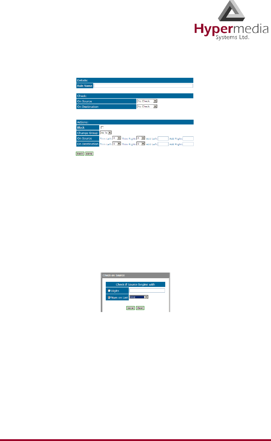
HMC Product Manual 81
Release 3.4: May 2010 Advanced Call Routing (ACR)
3. Click Add new rule. The Add New Rule screen is displayed.
Figure 78: Add New Rule Screen
4. In the Rule Name field, enter the name of the rule.
5. In the Check area, from either or both the On Source and the On Destination dropdown
menu, define the indication the rule will evaluate.
Note: On Source checks the origination phone number, that is, the phone number from which
the call was placed. On Destination checks the target phone number, that is, the phone
number of the called party.
If an indication is selected, a dialog box similar to the following is displayed:
Figure 79: Sample Check Dialog Box
No Check
The rule does not check the Source number.
Begins With
The rule checks if the On Source begins with either specific digits or a tag that appears on
the list.
Ends With
The rule checks if the On Source ends with either specific digits or a tag that appears on
the list.
In Range
The rule checks if the On Source range is within a specific range.

HMC Product Manual 82
Release 3.4: May 2010 Advanced Call Routing (ACR)
Identical to
The rule checks if the On Source is exactly the specific digits or tag that appears on the
list.
6. Complete the dialog box and click Save.
7. In the Actions area, define what ACR does when it identifies a number matching the indi-
cations defined in the Check area.
No Actions are Defined
If no actions are defined, the call are allowed as is.
Block
Calls matching the indications are not allowed.
Change Group
Calls matching the indications are routed through the LCR Group defined here.
On Source
Phone numbers of calls matching the indications are altered as defined here.
On Destination
Phone numbers of calls matching the indications are altered as defined here.
8. Click Save. The new rule is added to the ACR Rules screen.
9. Prioritize the rule. Use the arrows in the Priority column to increase or decrease a rules
prioritization.
Figure 80: Rule Prioritization Arrows
10. From the HMC navigation pane’s LCR branch, click the Rules sub-branch. The Rules
screen is displayed.
11. From the ACR column, select the checkbox in the Rule row that the ACR rules will be
applied to and click Save Settings.
HMC Product Manual 83
Release 3.4: May 2010 Callthrough
Callthrough
Use Callthrough to place calls, via the Hypergateway, to external numbers.
Note: Callthrough belongs to the Hypersavings Package and requires a separate license.
Users receive a dial-tone from the Hypergateway and can then place calls either:
• via the PBX to a corporate extension
• to a VoIP phone number
• to a Cellular phone number
• to a PSTN phone number
Figure 81: The Callthrough Sequence
To configure Callthrough:
1. From the HMC navigation pane’s LCR branch, click the Callthrough sub-branch. The
Callthrough screen is displayed.
Note: The Resources column lists the Resources found on the LCR Media Matrix screen. See
“Linking from the LCR Branch” on page 63.
1st Leg 2nd Leg
PBX
Cellular
HyperGateway
}
VoIP
Cellular
PSTN
VoIP
PSTN

HMC Product Manual 84
Release 3.4: May 2010 Callthrough
Figure 82: The Callthrough Screen
2. Select a Resource’s Set 1st Leg checkbox. When selected, this Resource can accept
Callthrough calls from the user. Also, when selected, this Resource is not used for stan-
dard calls.
Note: To clear a checkbox, from the LCR Media connections branch, select the Resource and
click Unlink.
Note: The Status column indicates if the Resource is or is not available. It also
indicates the type of equipment used to process the Callthrough.
Note: The Other Leg column displays the equipment used for the 2nd leg of the
Callthrough.
3. From the Group dropdown list, select the Group that will be allowed to use this
Callthrough Resource. These are the Groups that are defined in the VPN Groups sub-
branch of the Manage branch.
4. Repeat the procedure for other Resources that will be allocated to Callthrough calls.
5. Click Apply Settings.
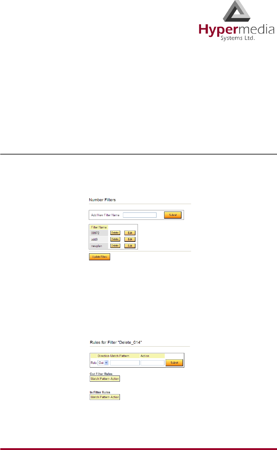
HMC Product Manual 85
Release 3.4: May 2010 Number Filters
Number Filters
Use Number Filters to manipulate numbers that are sent to, or received by, the Gateway. All
numbers are compared to the configured set of rules. If the number matches a rule, the rule is
applied and a new number is dialed.
Note: Number Filters belong to the Hypersavings Package and require a separate license.
Creating a Number Filter
To create a Number Filter:
1. From the HMC navigation pane, expand the Manage branch.
2. Click the Number Filters sub-branch. The Number Filters screen is displayed.
Figure 83: Number Filters Screen
3. In the Add New Filter Name field, enter a name for the new filter.
4. Click Submit. The Number Filters screen is displayed; the new filter appears in the list of
Filter Names.
5. Click the Edit button beside the new filter’s name. The Rules for Filter <name> screen
is displayed.
Figure 84: Edit Number Filters Screen
6. Select a Rule Direction.
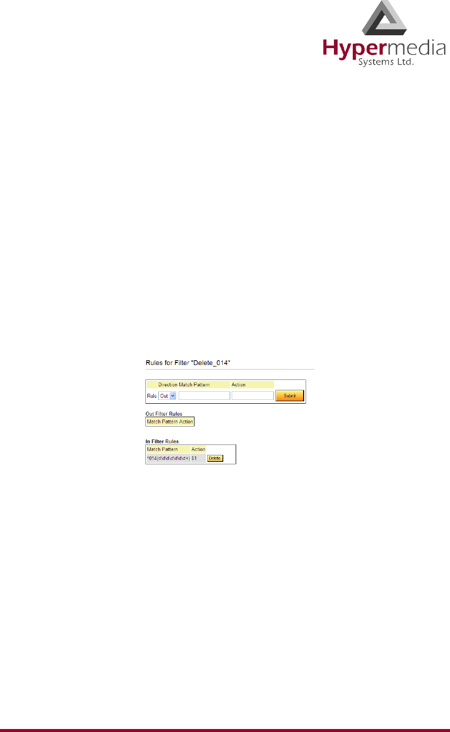
HMC Product Manual 86
Release 3.4: May 2010 Number Filters
Out
Use Out filters to apply the filters to outgoing calls. For example, if a number begins with
the Country Code 44 and is followed by seven or more digits, this filter—
^44(d\d\d\d\d\d\d+) $1 —removes the country code and dials only the digits following
the Country Code.
This second example is an Out filter that adds the suffix ‘9’ to all outgoing calls which
have five or more digits (for getting an outside line)— (\d\d\d\d\d+) 9$1
In
Use In filters to apply the filters to incoming calls.
7. Using standard Regular Expressions, enter the Match Pattern and the Action that will
occur when the pattern is matched.
Note: For more information about Regular Expressions, see:
http://www.regular-expressions.info
8. Click Submit. The Rule is listed in either the Out Filter Rules or the In Filter Rules list.
Figure 85: New Filter is Displayed
9. Click the Number Filters sub-branch.
10. Click Update Filters.
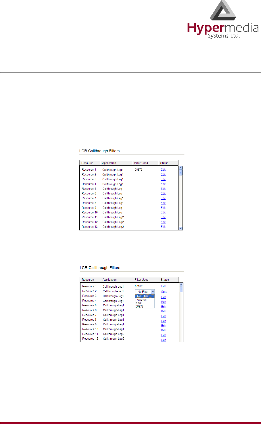
HMC Product Manual 87
Release 3.4: May 2010 Number Filters
Applying a Callthrough Filter
To apply a Callthrough Filter:
Note: Callthrough Filters belong to the Hypersavings Package and require a separate
license.
1. From the HMC navigation pane’s LCR branch, click the Callthrough Filters sub-branch.
The Callthrough Filters screen is displayed.
Figure 86: Callthrough Filter Screen
2. In the Status column, click Edit. In the Filter Used column, a dropdown list is displayed.
Figure 87: Filter Dropdown List
3. Select the filter.
4. Click Save.
5. Click Apply Settings.
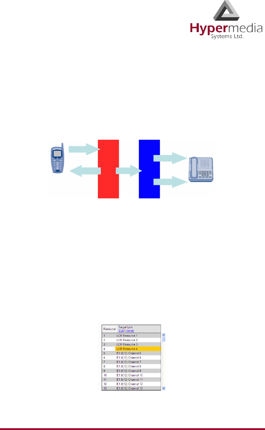
HMC Product Manual 88
Release 3.4: May 2010 Callback Triggers
Callback Triggers
A Callback Trigger is a number dialed by a User that causes the Gateway to authorize the user,
disconnect the call, and then call-back the User.
Note: Callback belongs to the Hypersavings Package and requires a separate license.
The most common type of Callback Trigger is a dedicated channel.
Figure 88: Callback Triggers Diagram
Note: If several Resources are dedicated to Callback, incoming calls are automatically
routed to the first available Resource.
For a Resource to be allocated to Callback, it must be linked to itself. Its Target Link from the
LCR Media Matrix must be “LCR Resource #” (see Figure # 89).
To configure Callback Trigger Resources:
1. From the HMC navigation pane’s LCR branch, click the Media Connections sub-branch.
The LCR Media Matrix is displayed.
2. Link an unassigned Resource to LCR. See “Linking from the LCR Branch” on page 63.
Figure 89: LCR Media Linked as Dedicated Channel
Trigger
1st Leg 2nd Leg
Extensions
PSTN
HyperGateway
Office PBX
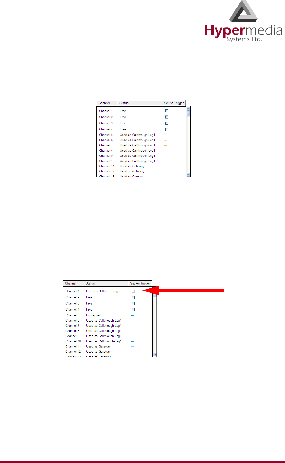
HMC Product Manual 89
Release 3.4: May 2010 Callback Triggers
3. From the HMC navigation pane’s LCR branch, click the Callback Triggers sub-branch.
The Callback Triggers page is displayed. A checkbox appears beside Resources that can
now be allocated as Callback Triggers.
Figure 90: LCR Callback Triggers Screen
4. Select the checkboxes. When selected, the Resource is allocated to Callback.
Note: To clear a checkbox, from the LCR Media connections branch, select the Resource and
click Unlink.
5. Click Apply Settings and wait for Configuration Saved to be displayed. The status
changes to “Used as Callback Trigger”.
Figure 91: Status “Used as Callback Trigger”
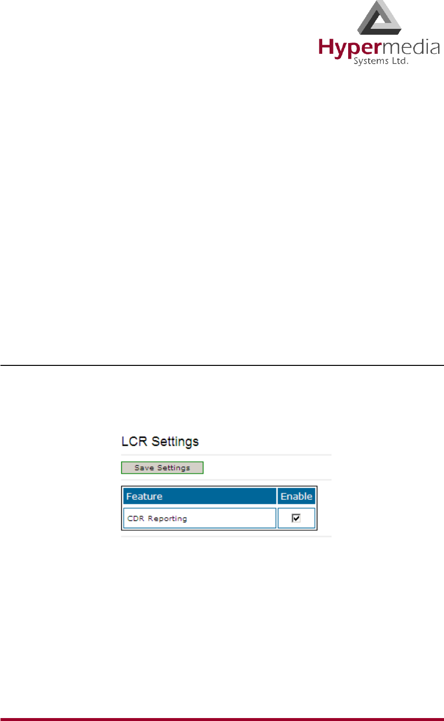
HMC Product Manual 90
Release 3.4: May 2010 CDR
CDR
Use the LCR Settings branch to enable the collection of Call Detail Records (CDR) and to
access CDR files.
On systems equipped with a CB card, an external storage device must be used. An SD card is
usually used but a USB disk-on-key may be used as well. The active file is located within the
internal system memory while completed files are moved onto the external storage device
during the night.
WARNING! Failure to plug in an external storage device will result in loss of CDR data.
The memory device should not be removed.
On PC-based systems, the CDR files are stored on the hard-drive.
On CB as well as PC based systems, the user is responsible for deleting old CDR files. This is
required both in order to prevent memory overflow as well as to be able to easily locate a file.
Enabling Collection of CDR
To enable collection of CDR files:
1. From the HMC navigation pane’s LCR branch, click the Settings sub-branch. The Fea-
ture list is displayed.
2. Select or clear the checkbox. When selected, the HMC collects Call Detail Records.
Note: Unless its size exceeds a predefined limit, only one CDR file is created each day.
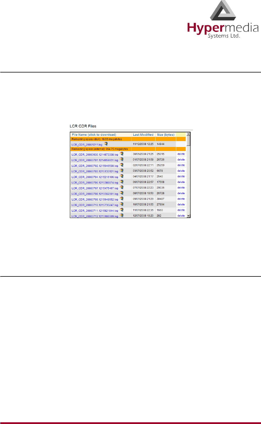
HMC Product Manual 91
Release 3.4: May 2010 CDR
Downloading a CDR File
To download a CDR file:
1. From the HMC navigation pane, expand the Monitor branch.
2. Expand the LCR Card sub-branch and select LCR CDRs. The list of CDR files is dis-
played.
3. Click a file name. The standard Windows Open dialog box is displayed.
4. Define the location where the file will be saved and click OK. The file is downloaded to
that location.
Deciphering the CDR File
A CDR line is created in the file each time a LCR call ends. All CDR fields appear on a single
line. For example:
12364,5003,0546858576,0546858576,1,2,2008-09-05 13:48:13,2008-09-05 13:48:14,2008-
09-05 13:48:24,2008-09-05 13:50:42,31,23,1,0,10,138
The entries are explained in Table 7. The format of the line is:
Call Index Number, Source Number, Original Destination Number, Filtered Destination
Number, Source Group Number, Destination Group Number, Dial Date & Time, Alert Date &
Time, Answer Date & Time, Hangup Date & Time, From Resource, To Resource, Source
Hangup Direction, Destination Hangup Direction, Hangup Reason, Call Duration

HMC Product Manual 92
Release 3.4: May 2010 CDR
Table 7: CDR Line Entries Explained
Entry Explanation
Call Index Number Counts from 0, does not reset when a new file is created
(i.e. when the date changes).
Source Number, Original Des-
tination Number Dialing and dialed numbers respectively.
Filtered Destination Number
Dialed number after a filter was applied to it (where rele-
vant). Otherwise identical to the Original Destination
Number.
Source Group Number, Desti-
nation Group Number
Group of LCR resources from which the call had arrived
to the LCR, as well as the group through which the call is
sent out from the LCR.
Dial Date & Time The moment the gateway received the call request (for-
mat = YYYY-MM-DD HH:MM:SS).
Alert Date & Time
The moment the remote party had begun ringing (if
reported by the remote party, and supported by the outgo-
ing resource).
Answer Date & Time The moment the call had been connected (i.e. answered
by the remote party).
Hangup Date & Time The moment any of the parties had terminated the call.
From Resource The resource through which the call entered the LCR
entity.
To Resource The resource through which the call was placed (after
being routed according to the LCR rules).
Source Hangup Direction
0 = source party had terminated the call
1 = call was terminated by LCR (due to termination by
the destination party, no route to destination, unavailable
destination resource, etc.)

HMC Product Manual 93
Release 3.4: May 2010 CDR
Destination Hangup Direction
0 = destination party had terminated the call
1 = call was terminated by LCR (due to termination by
the source party etc.)
Hangup Reason Cause code as reported by the party that had first termi-
nated the call.
Call Duration In seconds, measured between Answer-Time and
Hangup-Time.
Table 7: CDR Line Entries Explained
Entry Explanation
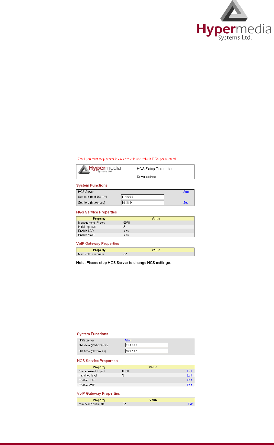
HMC Product Manual 94
Release 3.4: May 2010 Activating LCR in PC Cards
Activating LCR in PC Cards
When PC1 and PC2 cards are used, you must manually activate the LCR service. This is not
necessary when using PRI CB cards.
To manually activate LCR:
1. Click the Windows Start button > All Programs.
2. From the Hypermedia program group, select HGS Setup Parameters. The HGS Setup
Parameters logon screen is displayed.
3. Enter your password and click Submit. The HGS Setup Parameters screen is displayed.
Figure 92: HGS Setup Parameters Screen
4. From the HGS Server system function line, click Stop. A confirmation message indicates
that the service was stopped successfully.
5. Refresh the browser page, reenter your password and click Submit. The HGS Setup
Parameters screen is displayed in Edit mode.
Figure 93: HGS Setup Parameters Screen in Edit Mode

HMC Product Manual 95
Release 3.4: May 2010 Activating LCR in PC Cards
6. On the Disable LCR line, click Edit. The Value field becomes editable.
Figure 94: Editable Disable LCR Value Field
7. Enter 0 (zero). Zero indicates that LCR is enabled.
8. Click Save.
9. Click Submit.
10. From the HGS Server system function line, click Start. A confirmation message indi-
cates that the service was started successfully.
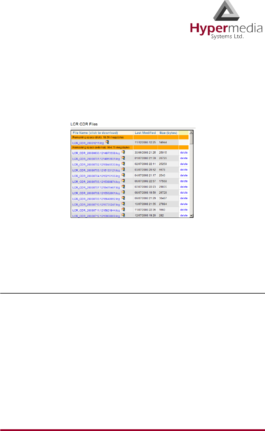
HMC Product Manual 96
Release 3.4: May 2010 LCR CDRs
LCR CDRs
To manage and download the daily LCR CDR files:
1. From the HMC navigation pane, expand the Monitor branch.
2. Expand the LCR Card sub-branch and select LCR CDRs. The list of CDR files is dis-
played.
Figure 95: LCR CDR Files Screen
3. Click a file name. The standard Windows Open dialog box is displayed.
4. Define the location where the file will be saved and click OK. The file is downloaded to
that location.
Deciphering the CDR File
A CDR line is created in the file each time a LCR call ends. All CDR fields appear on a single
line. For example:
12364,5003,0546858576,0546858576,1,2,2008-09-05 13:48:13,2008-09-05 13:48:14,2008-
09-05 13:48:24,2008-09-05 13:50:42,31,23,1,0,10,138
The entries are explained in Table 8 on page 97. The format of the line is:
Call Index Number, Source Number, Original Destination Number, Filtered Destination
Number, Source Group Number, Destination Group Number, Dial Date & Time, Alert Date &
Time, Answer Date & Time, Hang-up Date & Time, From Resource, To Resource, Source
Hang-up Direction, Destination Hang-up Direction, Hang-up Reason, Call Duration

HMC Product Manual 97
Release 3.4: May 2010 LCR CDRs
Table 8: CDR Line Entries Explained
Entry Explanation
Call Index Number Counts from 0, does not reset when a new file is created (i.e.
when the date changes).
Source Number, Original
Destination Number Dialing and dialed numbers respectively.
Filtered Destination Num-
ber
Dialed number after a filter was applied to it (where relevant).
Otherwise identical to the Original Destination Number.
Source Group Number,
Destination Group Number
Group of LCR resources from which the call had arrived to
the LCR, as well as the group through which the call is sent
out from the LCR.
Dial Date & Time The moment the gateway received the call request (format =
YYYY-MM-DD HH:MM:SS).
Alert Date & Time The moment the remote party had begun ringing (if reported
by the remote party, and supported by the outgoing resource).
Answer Date & Time The moment the call had been connected (i.e. answered by the
remote party).
Hangup Date & Time The moment any of the parties had terminated the call.
From Resource The resource through which the call entered the LCR entity.
To Resource The resource through which the call was placed (after being
routed according to the LCR rules).
Source Hangup Direction
0 = source party had terminated the call
1 = call was terminated by LCR (due to termination by the
destination party, no route to destination, unavailable destina-
tion resource, etc.)
Destination Hangup Direc-
tion
0 = destination party had terminated the call
1 = call was terminated by LCR (due to termination by the
source party etc.)
Hangup Reason Cause code as reported by the party that terminated the call.
Call Duration In seconds, measured between Answer-Time and Hangup-
Time.

HMC Product Manual 98
Release 3.4: May 2010 LCR CDRs
This page is intentionally blank.
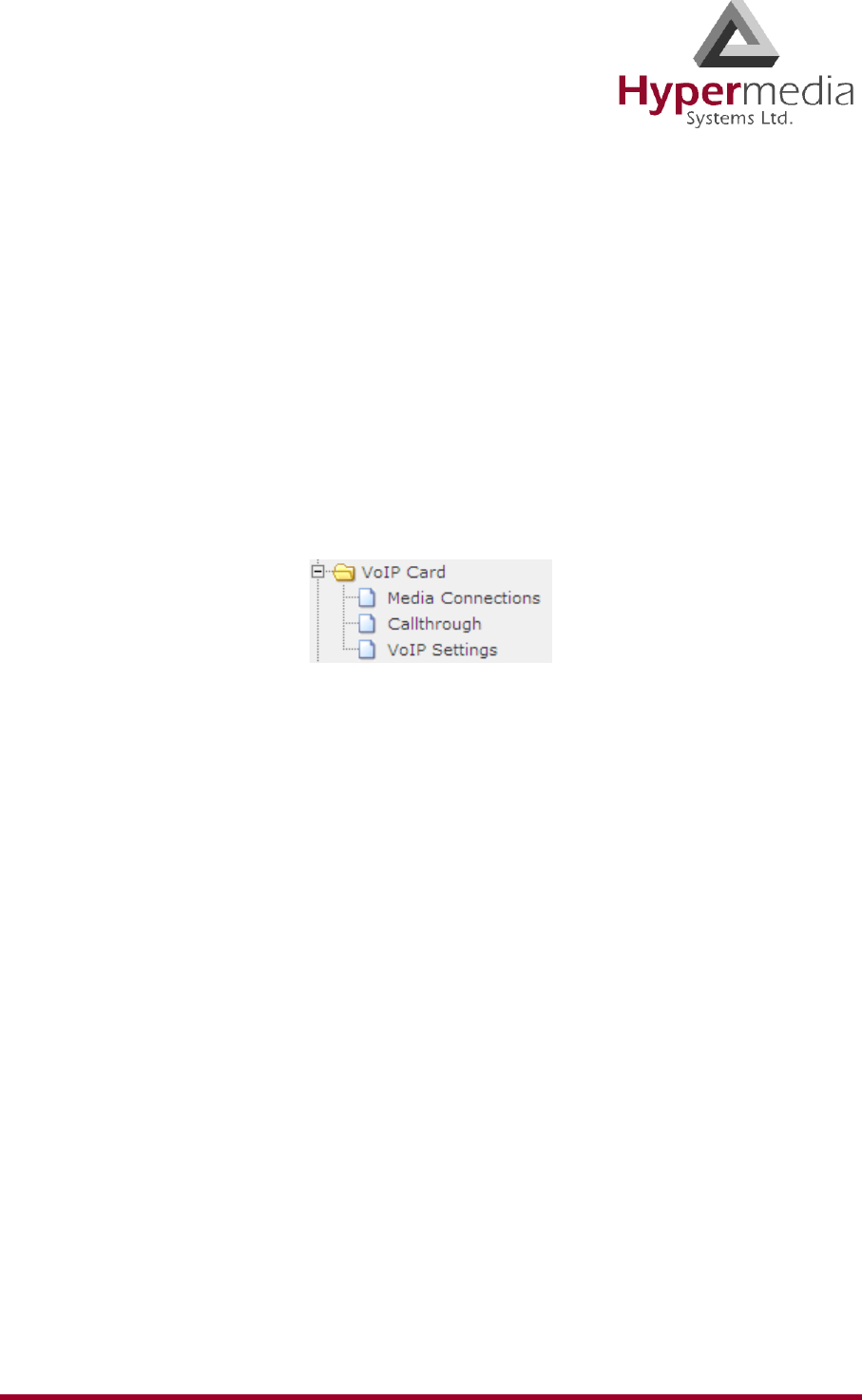
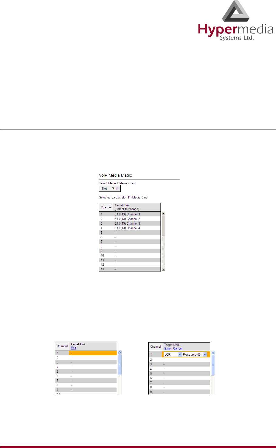
HMC Product Manual 100
Release 3.4: May 2010 VoIP Media Connections
VoIP Media Connections
Use the Media Connection screen to configure the connections from a VoIP card to other cards
and channels in the system, including the Cellular cards (CG) and the PRI cards (E1). The
matrix can be configured in any combination.
Associating/Linking VoIP Channels
To associate a VoIP channel with another media channel:
1. From the VoIP Card branch of the HMC navigation pane, click the Media Connections
sub-branch. The Media Matrix is displayed.
Figure 96: HMC VoIP Card Media Matrix Screen
2. If more than one slot is displayed, select a specific VoIP card. The Media Matrix of that
VoIP card is displayed.
3. Click within a channel row. The row turns yellow.
4. Click Edit. The row becomes configurable.
Figure 97: Media Matrix Row when Configurable
5. From the first dropdown list, allocate this channel to a card by selecting the card.
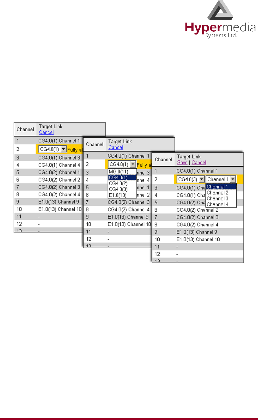
HMC Product Manual 101
Release 3.4: May 2010 VoIP Media Connections
Note: If all of the card’s channels are already allocated, the message “Fully allocated”
appears.
6. From the second dropdown list, assign this channel to a specific channel on the target
card.
Figure 98: Assigning a Target Link
7. Click Save. The configuration dropdown boxes are hidden.
8. Optionally, repeat the process for additional channels and other media types.
9. Click Apply Settings and wait for Configuration Saved to be displayed.
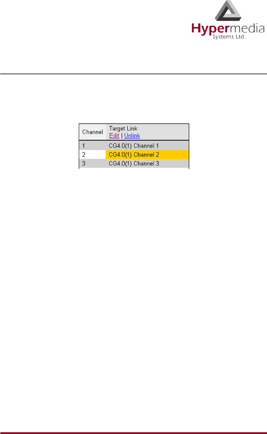
HMC Product Manual 102
Release 3.4: May 2010 VoIP Media Connections
Unlinking VoIP Allocations
To break an allocation:
1. From the VoIP Card branch of the HMC navigation pane, click the Media Connections
sub-branch. The Media Matrix is displayed.
2. Click within a channel row. The row turns yellow.
Figure 99: Breaking a PRI Target Link
3. Click Unlink.
4. Click Apply Settings and wait for Configuration Saved to be displayed.
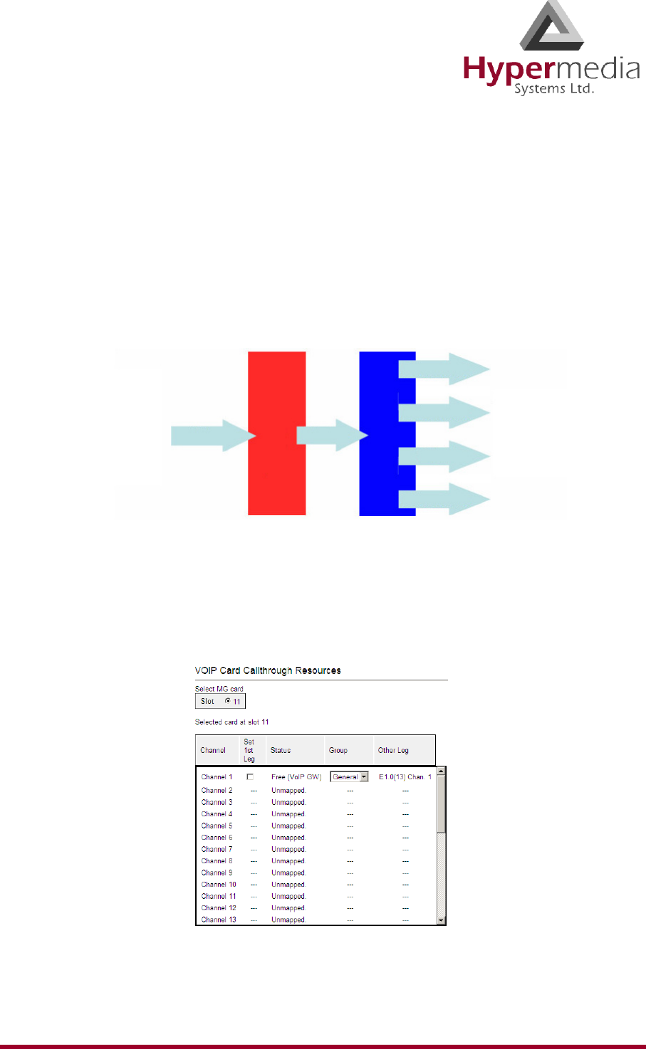
HMC Product Manual 103
Release 3.4: May 2010 Callthrough
Callthrough
Use Callthrough to place calls, via the Hypermedia Gateway, to external numbers. Users
receive a dial-tone from the Gateway and can then place calls either:
• via the PBX to a corporate extension
• to a VoIP phone number
• to a Cellular phone number
• to a PSTN phone number
To configure Callthrough:
1. Ensure that at least one VoIP Card > Media Connection channel is linked to the target
Callthrough equipment and is unallocated (see “VoIP Media Connections” on page 100).
2. From the VoIP Card branch of the HMC navigation pane, click the Callthrough sub-
branch. The Callthrough screen is displayed.
Figure 100: HMC VoIP Card Callthrough Resources Screen
1st Leg 2nd Leg
PBX
Cellular
HyperGateway
}
VoIP
Cellular
PSTN
VoIP
PSTN

HMC Product Manual 104
Release 3.4: May 2010 Callthrough
3. Select a Channel’s Set 1st Leg checkbox. When selected, this Channel can accept
Callthrough calls from the user. Also, when selected, this Channel is not used for standard
calls.
Note: To clear a checkbox, from the VoIP Card Media Connection branch, select the channel
and click Unlink.
Note: The Other Leg column displays the equipment used for the 2nd leg of the
Callthrough.
4. From the Group dropdown list, select the Group that will be allowed to use this
Callthrough Resource. These are the Groups that are defined in the VPN Groups sub-
branch of the Manage branch.
5. Repeat the procedure for other Resources that will be allocated to Callthrough calls.
6. Click Apply Settings and wait for Configuration Saved to be displayed.
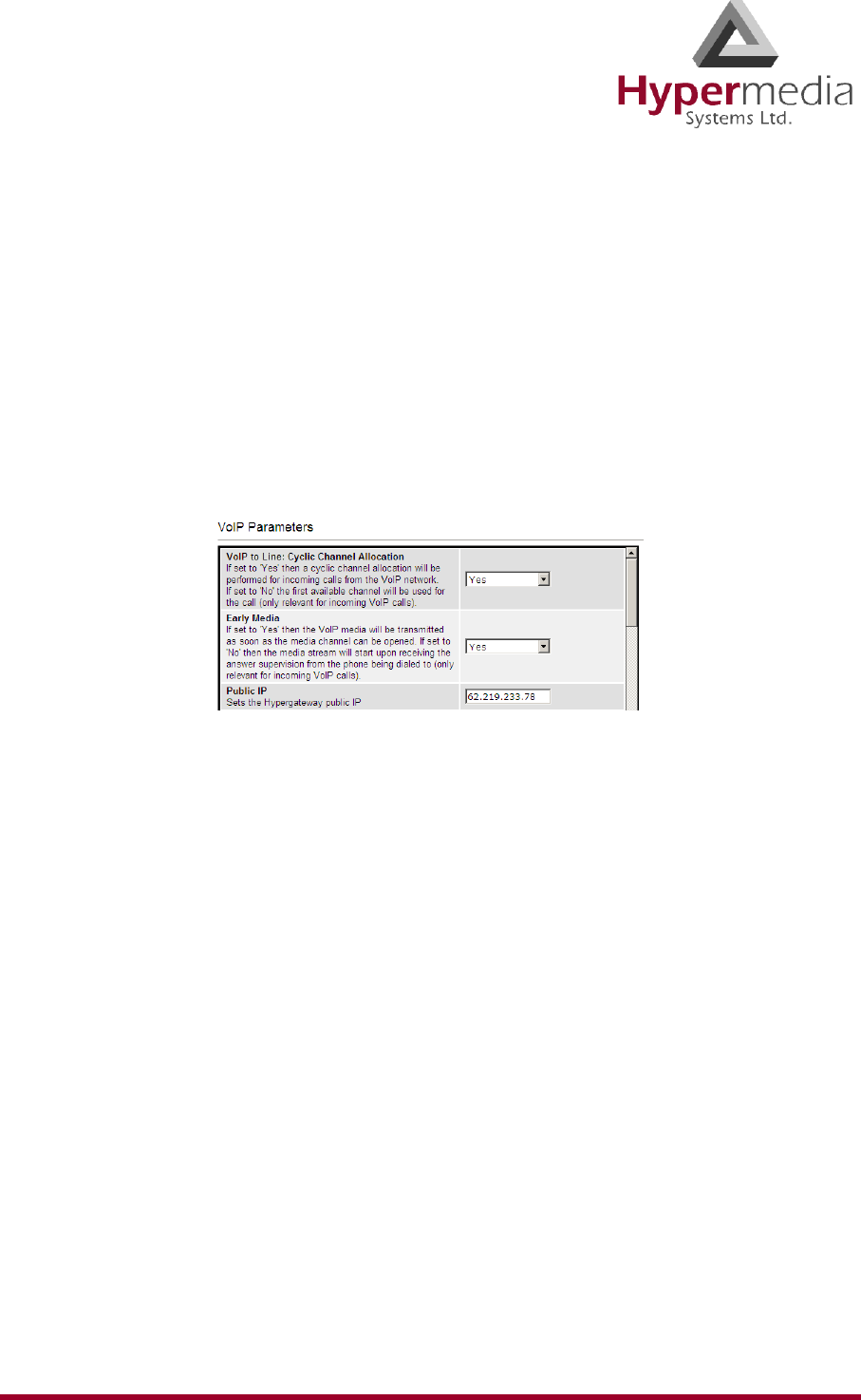
HMC Product Manual 105
Release 3.4: May 2010 VoIP Settings
VoIP Settings
An extensive set of parameters is used to support a Voice over IP network. Use the VoIP Set-
tings screen to configure VoIP parameters.
Note: Different versions of the VoIP Settings screen exist depending upon which VoIP
protocol is installed, H.323 or SIP.
1. From the VoIP Card branch of the HMC navigation pane, click the VoIP Settings sub-
branch. The VoIP Parameters screen is displayed.
Figure 101: HMC VoIP Card VoIP Parameters Screen
2. Configure the settings:
VoIP to Line: Cyclic Channel Allocation
Select either Yes or No. When Yes is selected, the Gateway assigns incoming VoIP calls
sequentially. Channel use is distributed evenly. When No is selected, the Gateway
assigns incoming VoIP calls to the first available channel.
Early Media
Select either Yes or No. When Yes is selected, the Gateway transmits VoIP media as soon
as the media channel is opened. When No is selected, the Gateway waits to transmit VoIP
media until it receives answer supervision from the destination phone.
Public IP
Enter the IP address that is used to access the Gateway from a remote location.
IP Precedence
Use IP Precedence to assign values from 0 (default) to 7 to classify and prioritize types of
traffic.
IP Type of Service
Use Type of Service (ToS) to manage the Quality of Service (QoS) throughout a network.
Number of Calls for ASR/ACD Statistics
This parameter determines how many of the most recent calls are evaluated for
determination of ASR and ACD statistics. For example, if the number 20 is entered only
the last 20 calls will be calculated and evaluated.

HMC Product Manual 106
Release 3.4: May 2010 VoIP Settings
User Input Indication
There are several protocols defining how VoIP handles the input of DTMF tones by users.
This parameter determines which of those protocols are used by the Gateway.
RFC2833 Payload
This defines the payload type used for creating/recreating DTMF tones.
Enable Codecs
From each drop-down menu, select the Codecs the Gateway will support. Order them
according to the sequence which the Gateway will use.
Payloads per Packet
Enter the number of Codec payloads that are carried by each RTP packet.
SIP Proxy
Enable or disable use of a SIP Proxy. When enabled, enter the IP address, Username, and
Password.
PIN Code Send Delay
Enter a period of time, measured in milliseconds, after which the PIN code will be sent to
the destination Gateway.
PIN Code Inter-Digit Delay
Enter a period of time, measured in milliseconds, between each PIN code digit sent.
3. Click Submit.
4. From the HMC navigation pane, click Save Configuration. Initialization takes about 15
seconds.
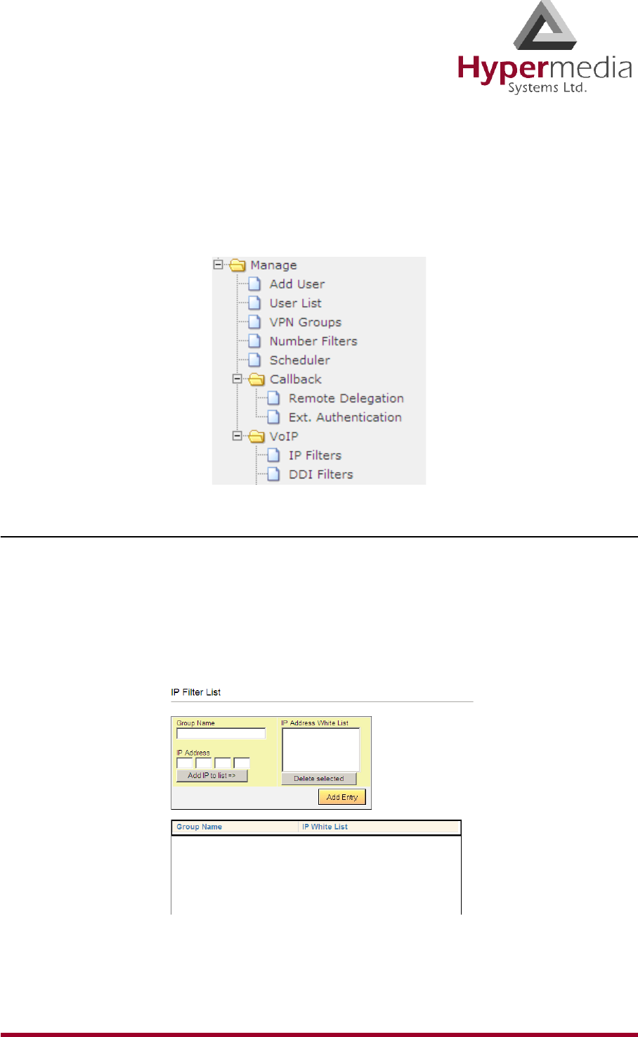
HMC Product Manual 107
Release 3.4: May 2010 VoIP Management Features
VoIP Management Features
Use VoIP Management Features to enhance the overall performance of the VoIP network.
VoIP Management Features enable you to restrict incoming calls, refined routing, and review
VoIP messages.
IP Filters
Use IP Filters to create a White List of IP addresses. This is a list of destinations prefixes that
can be dialed through the system.
1. From the HMC navigation pane, expand the Manage branch.
2. Expand the VoIP branch.
3. Click IP Filters. The IP Filter List screen is displayed.
Figure 102: HMC VoIP Card IP Filters List Screen
4. In the Group Name field, enter the name of an existing group or of a new group.
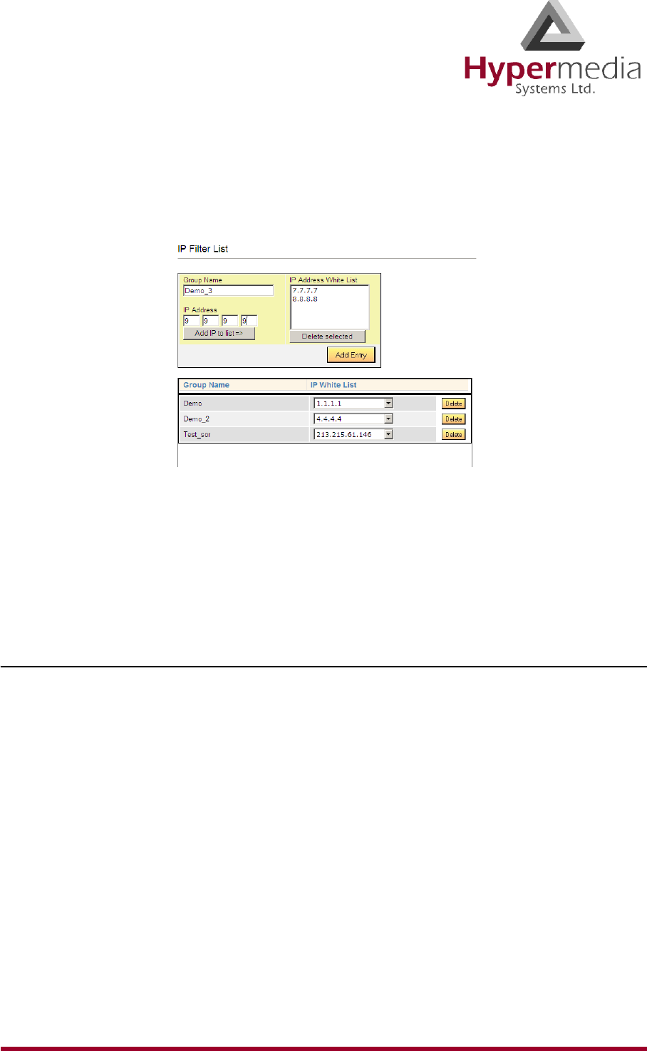
HMC Product Manual 108
Release 3.4: May 2010 VoIP Management Features
5. Enter an endpoint IP Address that the user is permitted to access via the VoIP Gateway.
6. Click Add IP to list. The new IP address appears in the IP Address White List box.
7. Repeat steps 5–6 until all IP addresses associated with that Group have been entered.
Figure 103: Configuring IP White List
8. Click Add Entry. The new Group and the IP White List are displayed in the box below.
Note: To review the list of IP addresses associated with a Group, open the dropdown list in
the Group’s Row.
DDI Filters (Direct Dial-in)
Use DDI Filters to create a White List of Direct Dial-In numbers and prefixes. This is a list of
endpoints from which a user is permitted to receive calls via the VoIP Gateway.
1. From the HMC navigation pane, expand the Manage branch.
2. Expand the VoIP branch.
3. Click DDI Filters. The DDI Filter List screen is displayed.
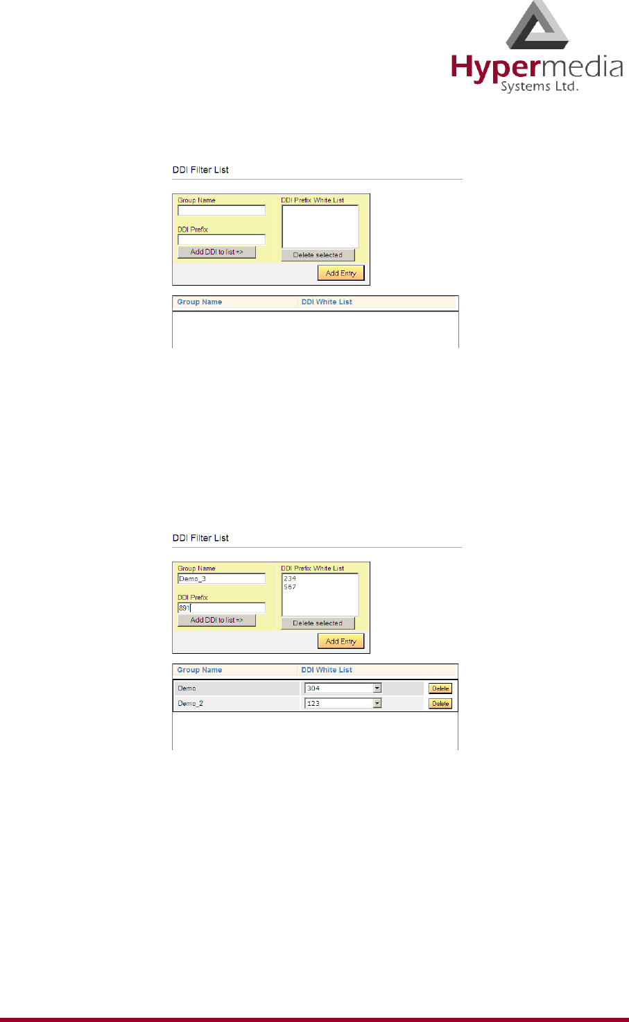
HMC Product Manual 109
Release 3.4: May 2010 VoIP Management Features
Figure 104: HMC VoIP Card DDI Filters List Screen
4. In the Group Name field, enter the name of an existing group or of a new group.
5. Enter a phone number—or a prefix to allow a group of numbers—from which a user is
permitted to receive calls via the VoIP Gateway.
6. Click Add DDI to list. The new DDI appears in the DDI Prefix White List box.
7. Repeat steps 5–6 until all DDI Prefixes associated with that Group have been entered.
Figure 105: Configuring DDI White List
8. Click Add Entry. The new Group and the DDI White List are displayed in the box below.
Note: To review the list of DDI Prefixes associated with a Group, open the dropdown list in
the Group’s Row.
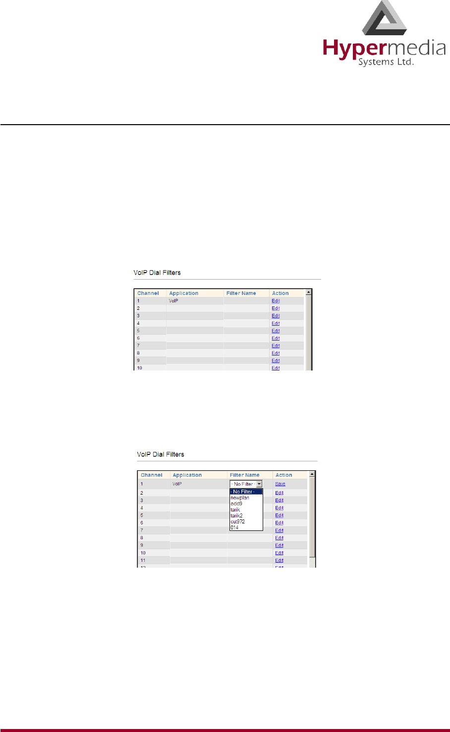
HMC Product Manual 110
Release 3.4: May 2010 VoIP Management Features
Dial Filters
Use the VoIP Dial Filters screen to apply Number Filters to a VoIP channel.
Note: For information on defining Number Filters, see “Number Filters” on page 125.
1. From the HMC navigation pane, expand the Manage branch.
2. Expand the VoIP branch.
3. Click Dial Filters. The VoIP Dial Filter List screen is displayed.
Figure 106: HMC VoIP Card Dial Filter List Screen
4. Click Edit. A dropdown list of existing filters is displayed in the Filter Name column.
5. Select a filter from the dropdown list. The prompt in the Action column changes to Save.
Figure 107: Configuring Dial Filters
6. Click Save.
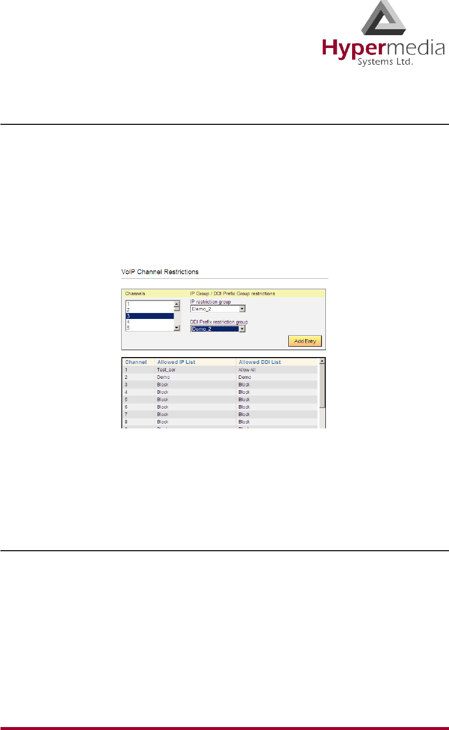
HMC Product Manual 111
Release 3.4: May 2010 VoIP Management Features
Call Routing
Use Call Routing to create a list of IP resources that can dial through the system.
1. Ensure that the required DDI filters (see p. 108) and IP filters (see p. 107) are defined.
Call Routing makes use of pre-defined DDI filters and IP filters.
2. From the HMC navigation pane, expand the Manage branch.
3. Expand the VoIP branch.
4. Click Call Routing. The VoIP Channel Restrictions screen is displayed.
5. From the Channel box, select the channel that the restrictions will be applied to.
Figure 108: HMC VoIP Card VoIP Channel Restrictions Screen
6. From the IP restriction group dropdown menu, select a pre-defined filter.
7. From the DDI Prefix restriction group dropdown menu, select a pre-defined DDI filter.
8. Click Add Entry. The restrictions are displayed in the table in the channel’s row.
Phone2Net Dial Plan
The Phone2Net Dial Plan connects phone calls to IP network phones. For example, when the
Hypermedia Gateway system receives an incoming call to: Dialed Number = 077444 it can
forward the call to the IP Phone at Destination IP = 192.168.1.67.
1. From the HMC navigation pane, expand the Manage branch.
2. Expand the VoIP branch.
3. Click Phone2Net Dial Plan. The Phone2Net Dialing Plan screen is displayed.
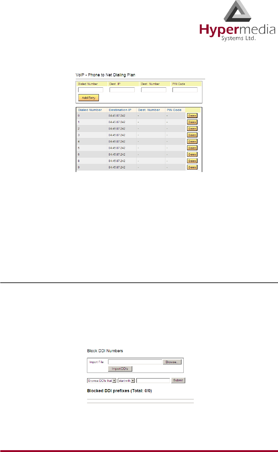
HMC Product Manual 112
Release 3.4: May 2010 VoIP Management Features
Figure 109: HMC VoIP Card Phone to Net Dialing Plan Screen
4. In the Dialed Number field, enter the phone number received by the Gateway.
5. Enter either:
•in the Dest. IP field, the IP address that the call will be connected to
•in the Dest. Number field, the phone number that the call will be connected to
6. If necessary, in the PIN Code field, enter the PIN code.
7. Click Add Entry. The new entry is displayed in the area below.
DDI Blocking
Use the DDI Blocking screen to import a comma-separated file (csv) file of phone numbers.
The Hypermedia Gateway will not dial those phone numbers.
1. From the HMC navigation pane, expand the Manage branch.
2. Expand the VoIP branch.
3. Click DDI Blocking. The DDI Blocking screen is displayed.
Figure 110: HMC VoIP Card DDI Blocking Screen
4. Click Browse and locate the file containing the DDIs.
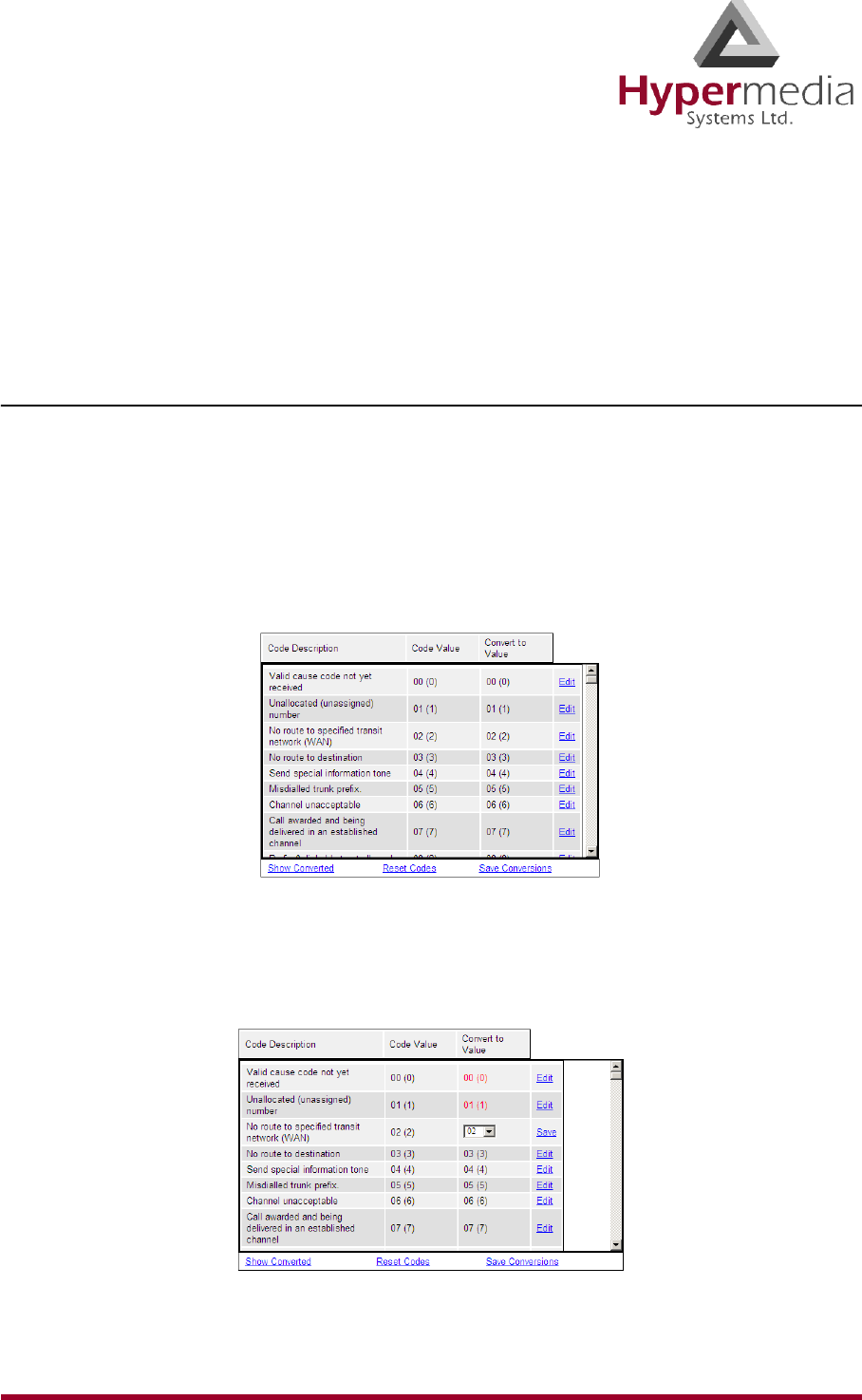
HMC Product Manual 113
Release 3.4: May 2010 VoIP Management Features
5. Click Import DDIs.
6. Use the two dropdown lists to refine the list of DDI numbers that will be blocked.
7. Click Submit. The list is displayed in the area below.
Cause Codes
Cause codes represent the reason for releasing the a call. The Hypermedia Gateway can
manipulate the releasing Cause code—that is, Convert to Value—if we do not want to report
the exact reason for call release.
1. From the HMC navigation pane, expand the Manage branch.
2. Expand the VoIP branch.
3. Click Cause Codes. The Cause Codes screen is displayed.
Figure 111: HMC VoIP Card Cause Codes Screen
4. On a code description line, click Edit. A dropdown menu is displayed in the Convert to
Value field.
Figure 112: Editable Value Field

HMC Product Manual 114
Release 3.4: May 2010 VoIP Management Features
5. Select a new value.
6. Click Save.
7. Click Submit.
8. Two additional options exist:
Show Converted
Displays the converted values.
Reset Codes
Assigns the original cause code values.
9. Click Save Conversions.
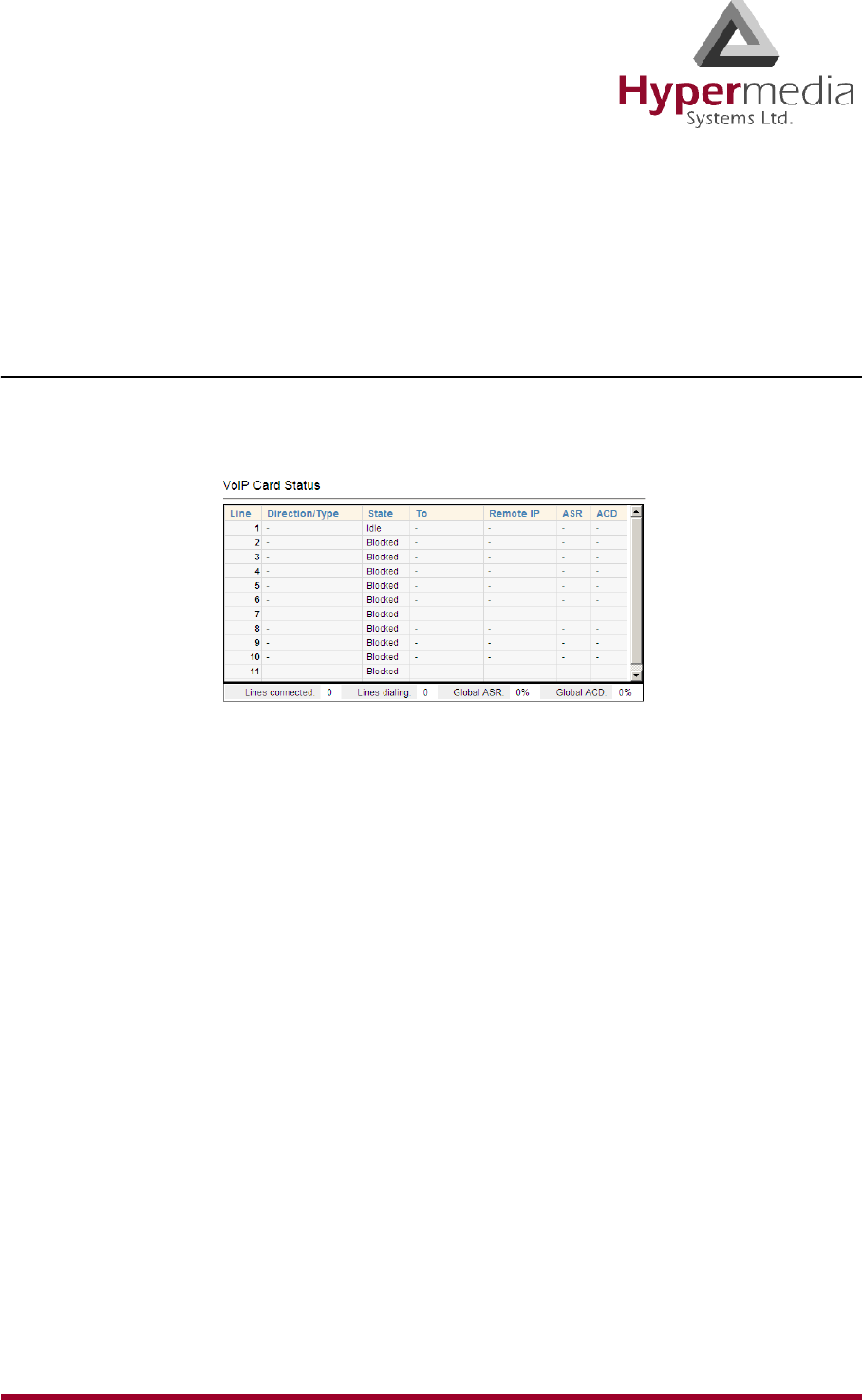
HMC Product Manual 115
Release 3.4: May 2010 Monitoring VoIP Cards
Monitoring VoIP Cards
Use the Monitor VoIP Cards > VoIP Status screen to review information about the status of the
VoIP card and to control line activity.
Review VoIP Card Information
To review VoIP Card information:
1. Expand the Monitor > VoIP Cards sub-branch and select VoIP Status.
Figure 113: VoIP Card Status Screen
2. Review the status of VoIP Lines. The following information is displayed:
Direction/Type
Calls can either be from network to the line or from the line to network.
State
“Connected” indicates that the channel is busy. “Idle” indicates that there is no call
activity on a channel.
To
This displays the destination number that the call is being made to.
Remote IP
This displays the IP address of destination endpoint or gateway.
ASR (Answer-Seizure Ratio)
This is the ratio of successfully connected calls to attempted calls and is also known as the
Call Completion Rate.
ACD (Average Call Duration)
This is the average duration of the calls routed by a VoIP provider. It is a quality
parameter given by the VoIP providers.
3. Review the totals. The total numbers of lines connected, lines dialing, and global ASR
and ACD are displayed below table.
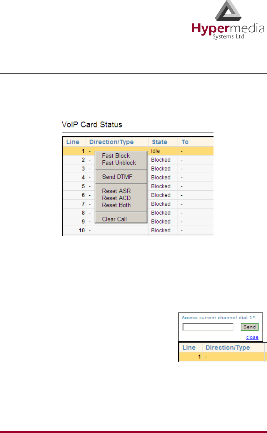
HMC Product Manual 116
Release 3.4: May 2010 Monitoring VoIP Cards
Controlling VoIP Line Activity
To control VoIP line activity:
1. Expand the Monitor > VoIP Cards sub-branch and select VoIP Status.
2. Right-click within a line. The line turns yellow and a popup menu is displayed.
Figure 114: VoIP Card Monitor Dropdown Menu
3. Select from the following controls:
Fast Block
Changes the State to Fast Blocked. The line cannot be used.
Fast Unblock
Returns the State to Idle. The line is available.
Send DTMF
Opens the Send DTMF tool. Enter the number of the
DTMF and click Send.
Reset ASR
Restarts the calculating of the ASR.
Reset ACD
Restarts the calculating of the ACD.
Reset Both
Restarts the calculating of both the ASR and the ACD.
Clear Call
Disconnects the current call. A confirmation message is displayed. Click OK to
disconnect the call.
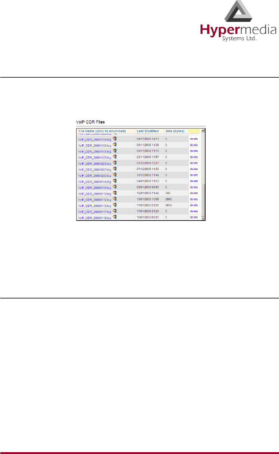
HMC Product Manual 117
Release 3.4: May 2010 Monitoring VoIP Cards
VoIP CDRs
To manage and download the daily VoIP CDR files:
1. Expand the Monitor > VoIP Cards sub-branch and select VoIP CDRs. The VoIP CDR
Files screen is displayed.
Figure 115: VoIP CDR Files Screen
2. Double-click a log-file. The standard browser Open or Save dialog box is displayed.
3. Click either Open or Save.
4. Review the file.
Deciphering the VoIP CDR File
A CDR line is created in the file each time a VoIP call ends. All CDR fields appear on a single
line without text-wrapping. Below is an example of a VoIP CDR entry but distorted by text-
wrapping:
60,2009-01-12 T 11:48:51,2009-01-12 T 11:48:51,"102",0774445003,,2009-01-12 T
11:48:55,,212.143.136.19,212.143.136.19,16386,2,12,0,0,0,0,0,10
The entries are explained in Table 9 on page 118.

HMC Product Manual 118
Release 3.4: May 2010 Monitoring VoIP Cards
Table 9: Deciphering the VoIP CDR File
Column
Number Field Name Description
1 CallID A unique identifier for the call
2 Received The time when the incoming call was received
3 Dialed
The time when the remote party was dialed to (may
be empty if no resources were available to place the
call)
4Alerting
The time when an alerting signal was received from
the remote party (may be in the if no resources were
available to complete the call or a fan error or hang-
up event was received prior to this stage).
5 E164Src The number that the call is being made from.
6 E164Dest The number that the call is being made to.
7Start Time
Time when the call started in ISO 8601 format (two-
way RTP audio channels open)
(e.g. 2004-08-08 T 10:24:18 +0200). May be empty
if call did not connect.
8 End Time Time when call ended in ISO 8601 format (two-way
RTP audio channels closed)
9 Duration Duration of call in seconds
10 Remote Signal IP IP address of remote H.323/SIP endpoint / gateway
11 RemoteMediaADDR IP address of remote RTP endpoint
12 Remote Media Port IP Port of remote RTP endpoint
13 Local Channel Channel used on VoIP card
14 Remote Card Slot Slot number of card connected to VoIP channel
15 Called Direction
Direction of call. Possible values are:
0 – Call from network to line
1 – Call from line to network

HMC Product Manual 119
Release 3.4: May 2010 Monitoring VoIP Cards
16 Hangup Initiator
Initiator of hang-up. Possible values are:
0 – Network
1 – Line
17 TxRTP Number of RTP packets sent during the session
18 RxRTP Number of RTP packets received during the session
19 Lost RTP Number of RTP packets lost during the session
20 Hangup Reason Q.931 reason for call hang-up
Table 9: Deciphering the VoIP CDR File
Column
Number Field Name Description

HMC Product Manual 120
Release 3.4: May 2010 Monitoring VoIP Cards
This page is intentionally blank.
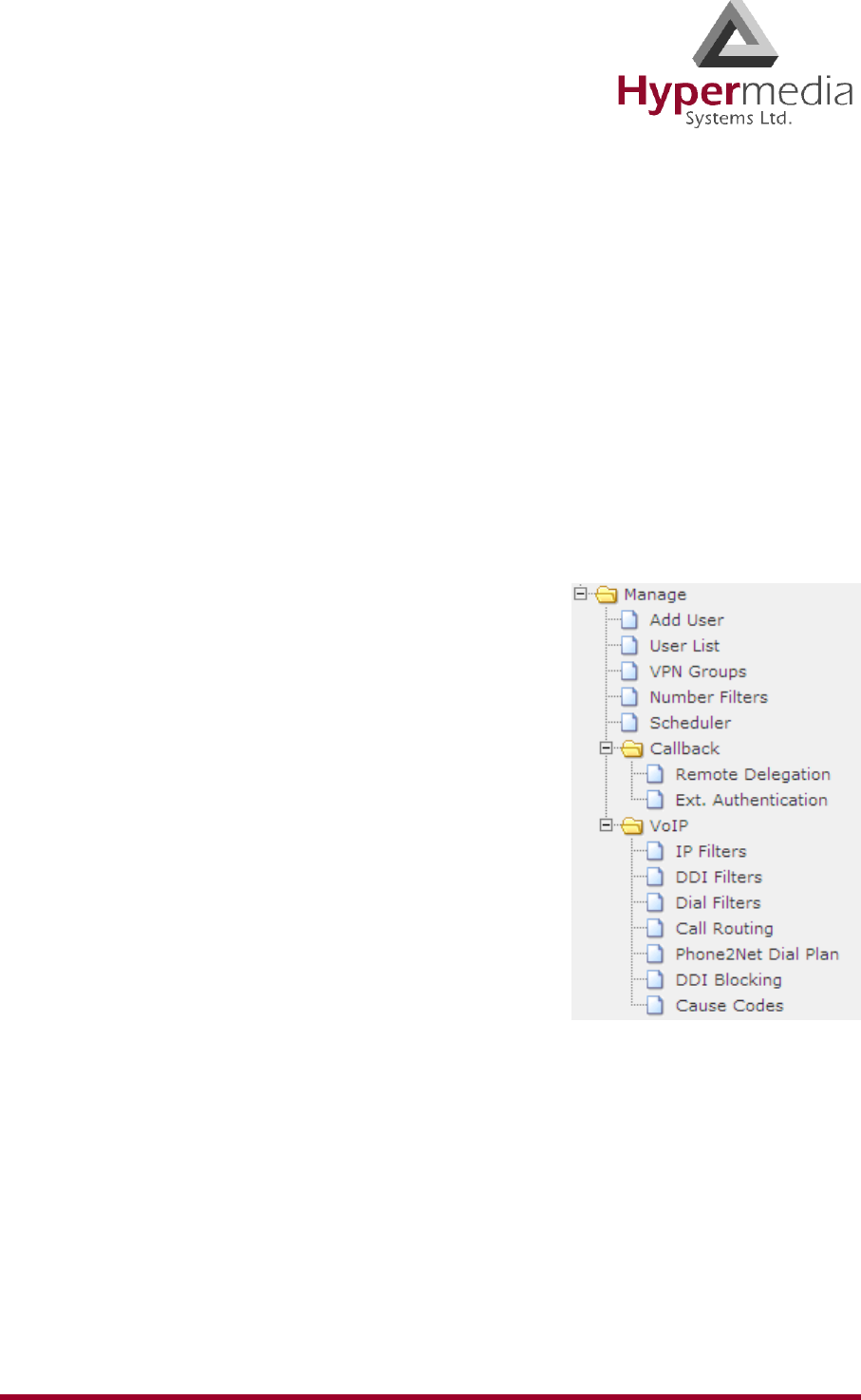
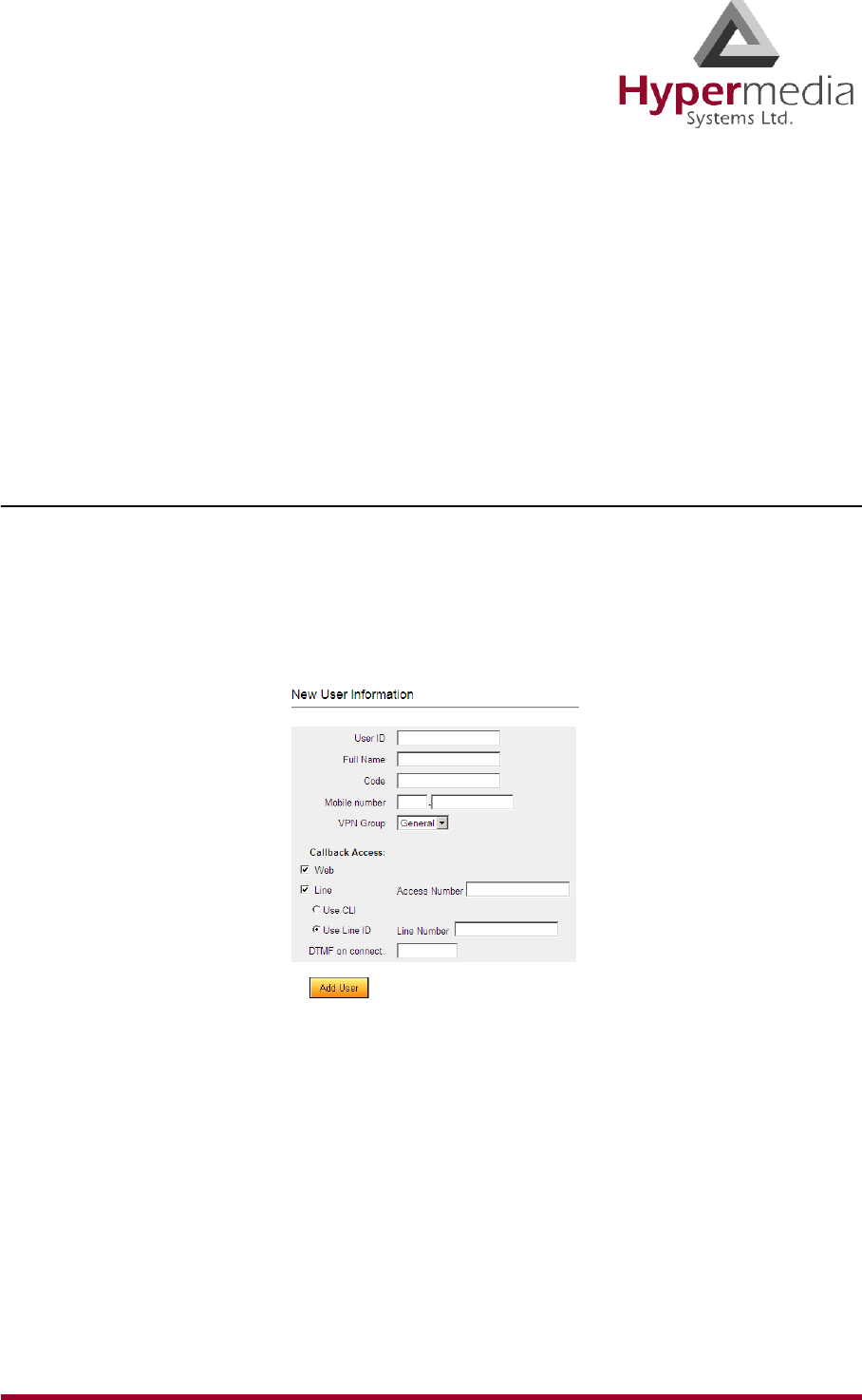
HMC Product Manual 122
Release 3.4: May 2010 User Management
User Management
Use this screen when configuring Callback and Callthrough. Perform initial user configuration
using the Add User screen. To change a user’s configuration, and to delete a user, use the User
List screen.
Note: These User Management features belong to the Hypersavings Package and require a
separate license.
Add User
Use the Add User branch to define Gateway users and to manage their Callback access.
To add a new user:
1. From the HMC navigation pane, expand the Manage branch.
2. Click the Add User sub-branch. The New User Information screen is displayed.
Figure 116: HMC New User Screen
3. Enter the following user information:
User ID
This can be any string. The information reappears in the All Users table.
Full Name
This information reappears in the All Users table.
Code
Any random string of numbers and letters.
Mobile Number
Enter the user’s mobile device number.

HMC Product Manual 123
Release 3.4: May 2010 User Management
VPN Group
From the dropdown menu, assign the user to a VPN Group.
4. Define the users Callback access:
Web
This feature is currently being developed. Contact Technical Support for information
about using a browser-based visual Callback Dialer to dial a destination number and
receive a callback call on a registered callback number.
Line
When selected, the user is able to trigger a Callback via a telephone call. If selected:
a. In the Access Number field, enter the phone number the user dials to access the
Hypermedia Gateway.
b. Select one of the following:
• Use CLI
The Hypermedia Gateway uses Caller Line Identification (CLI) to automatically
identify the phone number to be called back.
• Use Line ID
Enter the Line Number. The Hypermedia Gateway calls back the number
entered in the Line Number field.
DTMF on connect
Enter the DTMF sequence the user must push to gain access to the Gateway.
5. Click Add User and wait for the “User added successfully” message.
User List
Use the User List to review a list of defined Gateway users and to modify their definitions.
1. From the HMC navigation pane, expand the Manage branch.
2. Click the User List sub-branch. The User List screen is displayed.
Figure 117: HMC User List
3. Optionally, click a table heading cell to resort the entries.
4. Optionally, click Modify to change a User’s definitions.
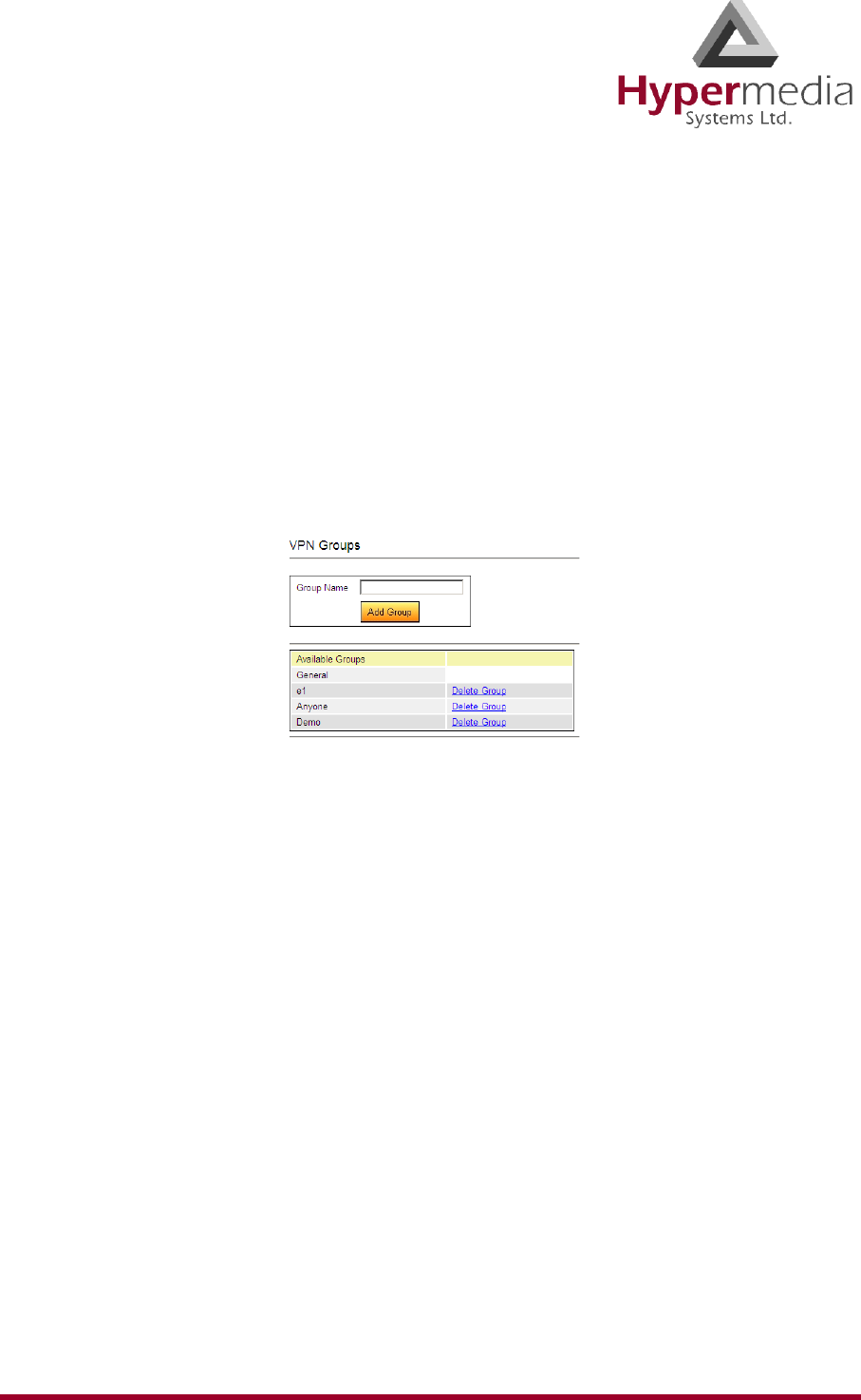
HMC Product Manual 124
Release 3.4: May 2010 VPN Groups
VPN Groups
Create VPN Groups to enable organized assignment of features or parameters. For example,
Callback resources can be reserved for members of a specific VPN Group.
Note: VPN Groups belong to the Hypersavings Package and require a separate license.
To create a VPN Group:
1. From the HMC navigation pane, expand the Manage branch.
2. Click the VPN Groups sub-branch. The VPN Groups screen is displayed.
Figure 118: HMC VPN Groups Screen
3. In the Group Name field, enter a name for the new Group.
4. Click Add Group. The new Group Name will be saved and added to the column of
Available Groups.
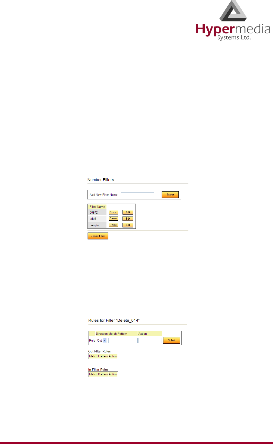
HMC Product Manual 125
Release 3.4: May 2010 Number Filters
Number Filters
Use Number Filters to perform advanced manipulations on numbers that are sent to, or
received by, the Gateway. All numbers are compared to the configured set of rules. If the
number matches a rule, the rule is applied and a new number is dialed.
Note: The Number Filters feature is relevant only to Hypermedia HG4000 Gateways.
To create a Number Filter:
1. From the HMC navigation pane, expand the Manage branch.
2. Click the Number Filters sub-branch. The Number Filters screen is displayed.
Figure 119: Number Filters Screen
3. In the Add New Filter Name field, enter a name for the new filter.
4. Click Submit. The Number Filters screen is displayed; the new filter appears in the list of
Filter Names.
5. Click the Edit button beside the new filter’s name. The Rules for Filter <name> screen
is displayed.
Figure 120: Edit Number Filters Screen
6. Select a Rule Direction.

HMC Product Manual 126
Release 3.4: May 2010 Number Filters
Out
Use Out filters to apply the filters to outgoing calls. For example, if a number begins with
the Country Code 44 and is followed by seven or more digits, this filter—
^44(d\d\d\d\d\d\d+) $1 —removes the country code and dials only the digits following
the Country Code.
This second example is an Out filter that adds the suffix ‘9’ to all outgoing calls which
have five or more digits (for getting an outside line)— (\d\d\d\d\d+) 9$1
In
Use In filters to apply the filters to incoming calls.
7. Using standard Regular Expressions, enter the Match Pattern and the Action that will
occur when the pattern is matched.
Note: For more information about Regular Expressions, see: http://www.regular-
expressions.info
8. Click Submit. The Rule is listed in either the Out Filter Rules or the In Filter Rules list.
Figure 121: New Filter is Displayed
9. Click the Number Filters sub-branch.
10. Click Update Filters.
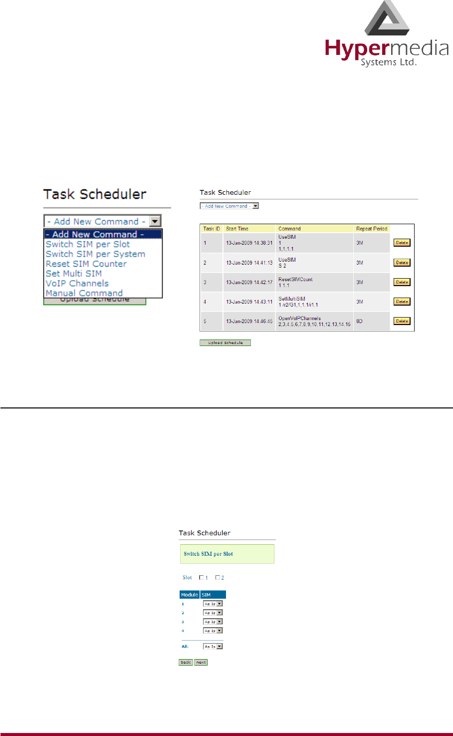
HMC Product Manual 127
Release 3.4: May 2010 Scheduler
Scheduler
Use the Task Scheduler to configure the Gateway to repeat commands at scheduled intervals.
Five commands are preconfigured. In addition, it is possible to manually configure a com-
mand.
Figure 122: Dropdown Menu of Tasks and Table of Scheduled Tasks
Switch SIM per Slot
Use the Switch SIM per Slot task to configure a GSM slot to use specific SIM cards for a
defined period of time.
1. From the HMC navigation pane, expand the Manage branch.
2. Click the Scheduler sub-branch. The Task Scheduler screen is displayed.
3. From the Add New Command dropdown menu, select Switch SIM per Slot. The Task
Scheduler automatically advances to the next screen.
Figure 123: Task Scheduler Switch SIM per Slot Screen
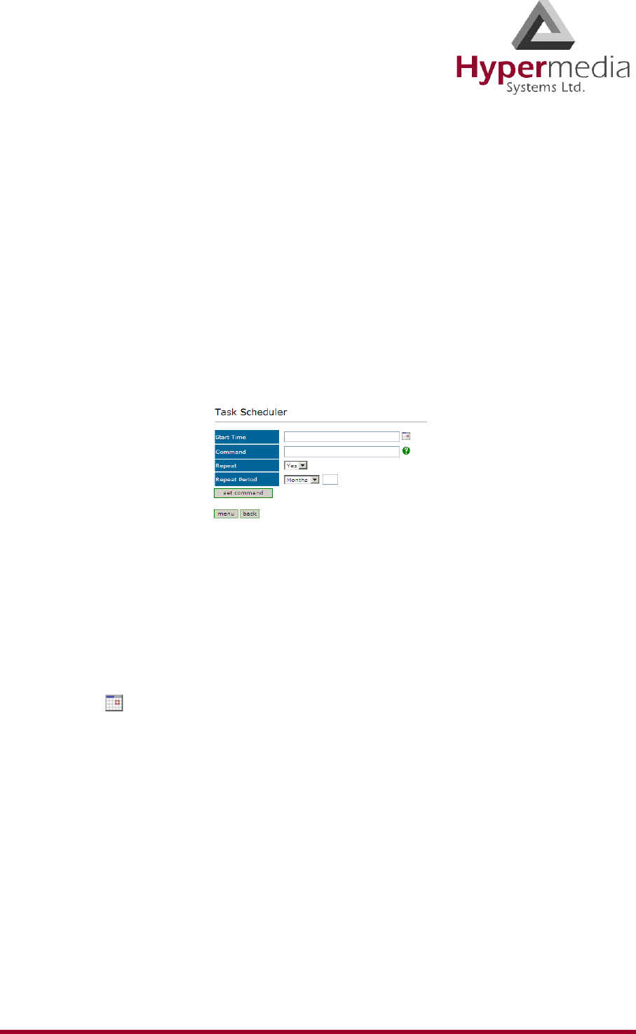
HMC Product Manual 128
Release 3.4: May 2010 Scheduler
4. Configure the task parameters:
Slot
Select or clear the checkboxes. Each checkbox represents the GSM card located in the
numbered slot counting from the left.
SIM
From each module’s dropdown menu, select the SIM card that that module will use.
Select As Is if the Gateway does not change the SIM activity.
Note: Use the All dropdown menu to assign the same SIM card to all four modules.
5. Click Next. The Set Command screen, with the command syntax, is displayed.
Figure 124: Task Scheduler Set Command Screen
WARNING! Clicking menu deletes the new task. The table of schedules tasks is
redisplayed.
6. Configure the task’s schedule:
a. Click (calendar icon). A calendar opens in a new browser tab.
Note: First, set the time. As soon as you click the date, the browser tab closes and the date
and time are entered into the Start Time field.
b. Enter the time that the command will start.
c. Enter the date that the command will start. When you click the date, the browser tab
closes and the date and time are entered into the Start Time field.
d. From the Repeat drop-down menu, select either Yes or No.
e. If the task is configured to repeat, select a Repeat Period. The Repeat Period can be
either months, days, hours, or minutes.
7. Click Set Command. The new Task is displayed in the Task Scheduler screen.
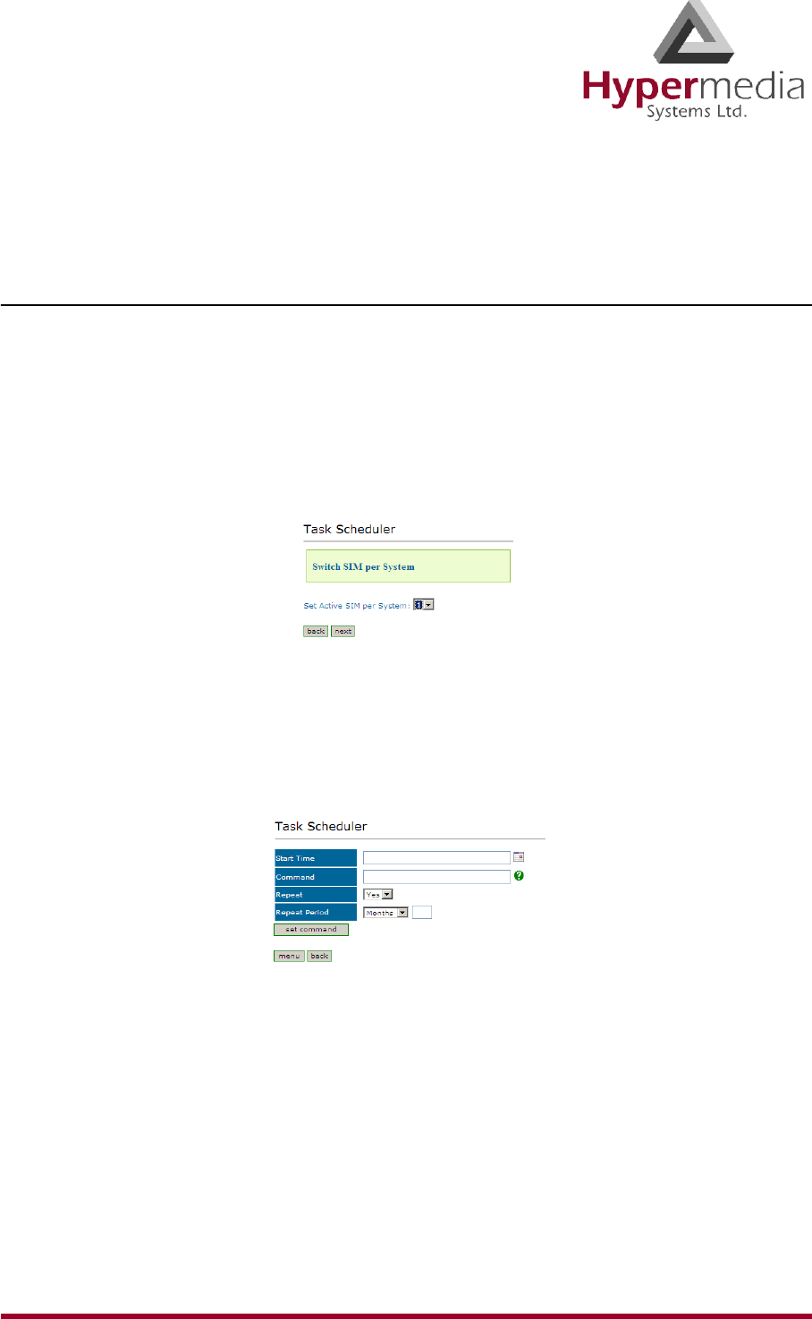
HMC Product Manual 129
Release 3.4: May 2010 Scheduler
8. Click Upload Schedule. The Server activates the schedule according to the defined dates
and times.
Switch SIM per System
Use the Switch SIM per System task to configure a Gateway to use one specific SIM card for a
defined period of time.
1. From the HMC navigation pane, expand the Manage branch.
2. Click the Scheduler sub-branch. The Task Scheduler screen is displayed.
3. From the Add New Command dropdown menu, select Switch SIM per System. The
Task Scheduler automatically advances to the next screen.
Figure 125: Task Scheduler Switch SIM per System Screen
4. From the Set Active SIM per System dropdown menu, select the SIM card that the entire
system will use.
5. Click Next. The Set Command screen, with the command syntax, is displayed.
Figure 126: Task Scheduler Set Command Screen
WARNING! Clicking menu deletes the new task. The table of schedules tasks is
redisplayed.
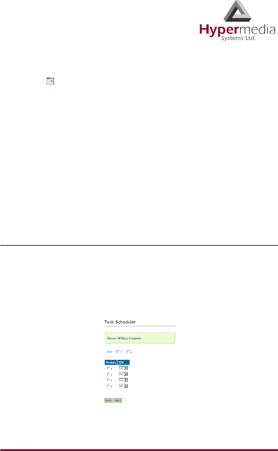
HMC Product Manual 130
Release 3.4: May 2010 Scheduler
6. Configure the task’s schedule:
a. Click (calendar icon). A calendar opens in a new browser tab.
Note: First, set the time. As soon as you click the date, the browser tab closes and the date
and time are entered into the Start Time field.
b. Enter the time that the command will start.
c. Enter the date that the command will start. When you click the date, the browser tab
closes and the date and time are entered into the Start Time field.
d. From the Repeat drop-down menu, select either Yes or No.
e. If the task is configured to repeat, select a Repeat Period. The Repeat Period can be
either months, days, hours, or minutes.
7. Click Set Command. The new Task is displayed in the Task Scheduler screen.
8. Click Upload Schedule. The Server activates the schedule according to the defined dates
and times.
Reset SIM Counter
Use the Reset SIM Counter task to configure a GSM slot’s module to restart the recording of
time in use.
1. From the HMC navigation pane, expand the Manage branch.
2. Click the Scheduler sub-branch. The Task Scheduler screen is displayed.
3. From the Add New Command dropdown menu, select Reset SIM Counter. The Task
Scheduler automatically advances to the next screen.
Figure 127: Task Scheduler Reset SIM Counter Screen
4. Configure the task parameters:
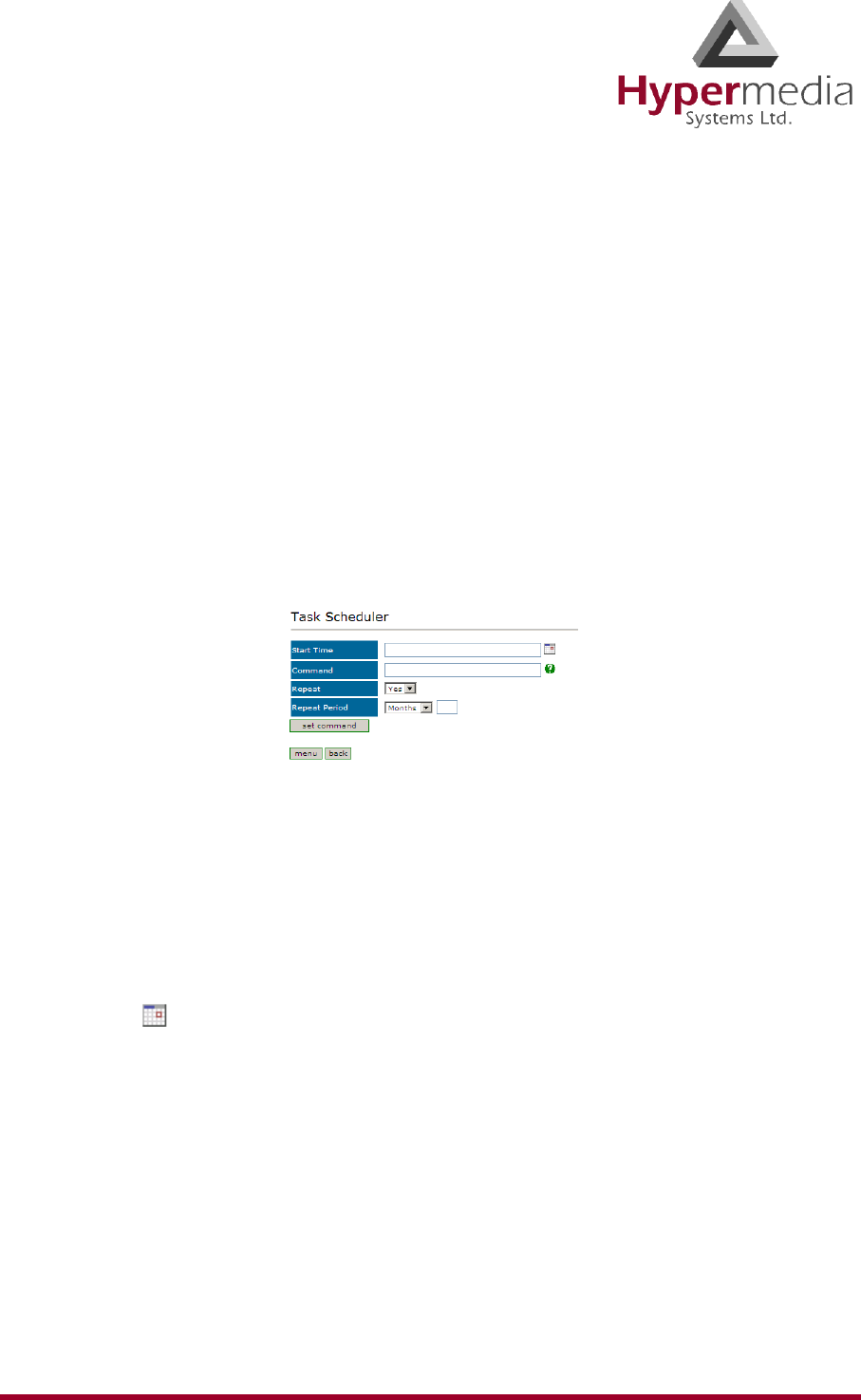
HMC Product Manual 131
Release 3.4: May 2010 Scheduler
Slot
Select or clear the checkboxes. Each checkbox represents the GSM card located in the
numbered slot counting from the left.
Module
From the Module column, select the module upon which the task will be performed. Only
one Module can be selected.
SIM
From the module’s SIM dropdown menu, select the SIM card for which the count will be
reset.
Note: Select All to reset the count on all of the module’s SIM cards.
5. Click Next. The Set Command screen, with the command syntax, is displayed.
Figure 128: Task Scheduler Set Command Screen
WARNING! Clicking menu deletes the new task. The table of schedules tasks is
redisplayed.
6. Configure the task’s schedule:
a. Click (calendar icon). A calendar opens in a new browser tab.
Note: First, set the time. As soon as you click the date, the browser tab closes and the date
and time are entered into the Start Time field.
b. Enter the time that the command will start.
c. Enter the date that the command will start. When you click the date, the browser tab
closes and the date and time are entered into the Start Time field.
d. From the Repeat drop-down menu, select either Yes or No.
e. If the task is configured to repeat, select a Repeat Period. The Repeat Period can be
either months, days, hours, or minutes.
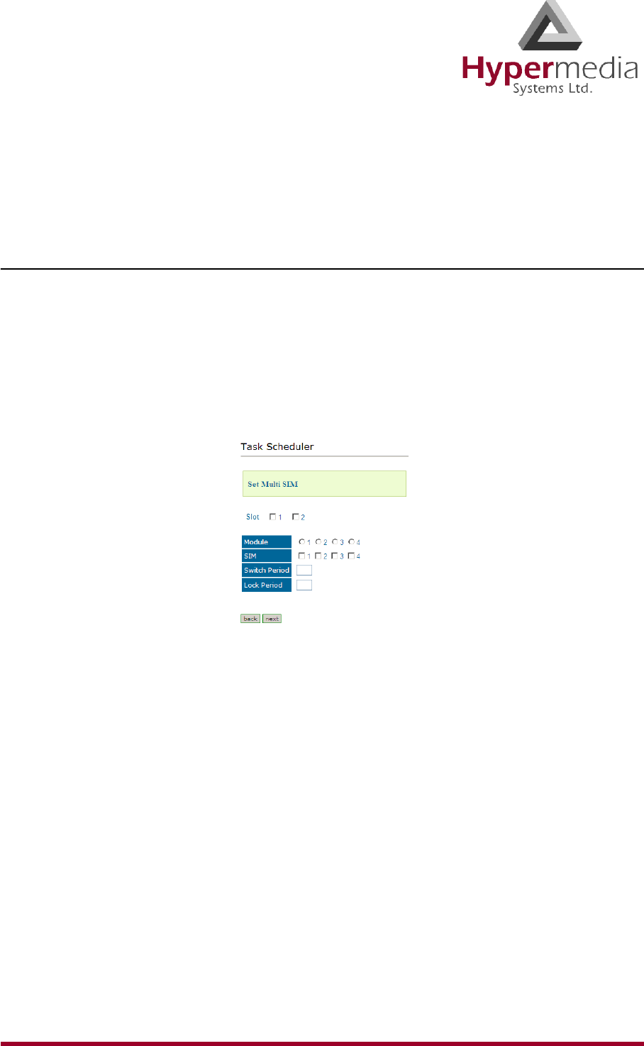
HMC Product Manual 132
Release 3.4: May 2010 Scheduler
7. Click Set Command. The new Task is displayed in the Task Scheduler screen.
8. Click Upload Schedule. The Server activates the schedule according to the defined dates
and times.
Set Multi SIM
Use the Set Multi SIM task to create cycles that define when each SIM card is used and after
how much time a SIM card is removed from usage.
1. From the HMC navigation pane, expand the Manage branch.
2. Click the Scheduler sub-branch. The Task Scheduler screen is displayed.
3. From the Add New Command dropdown menu, select Set Multi SIM. The Task Sched-
uler automatically advances to the next screen.
Figure 129: Task Scheduler Set Multi SIM Screen
4. Configure the task parameters:
Slot
Select or clear the checkboxes. Each checkbox represents the cellular card located in the
numbered slot counting from the left.
Module
From the Module row, select the module number on the cellular card upon which the task
will be performed. Only one Module can be selected.
SIM
From the SIM row, select the checkbox to include the SIM card in the cycle.
Switch Period
Enter an amount of time measured in minutes that each SIM card is active. When the
period of time expires, the next SIM card become active.
Lock Period
Enter an amount of time measured in minutes after which the SIM cards can no longer be
used to place calls.
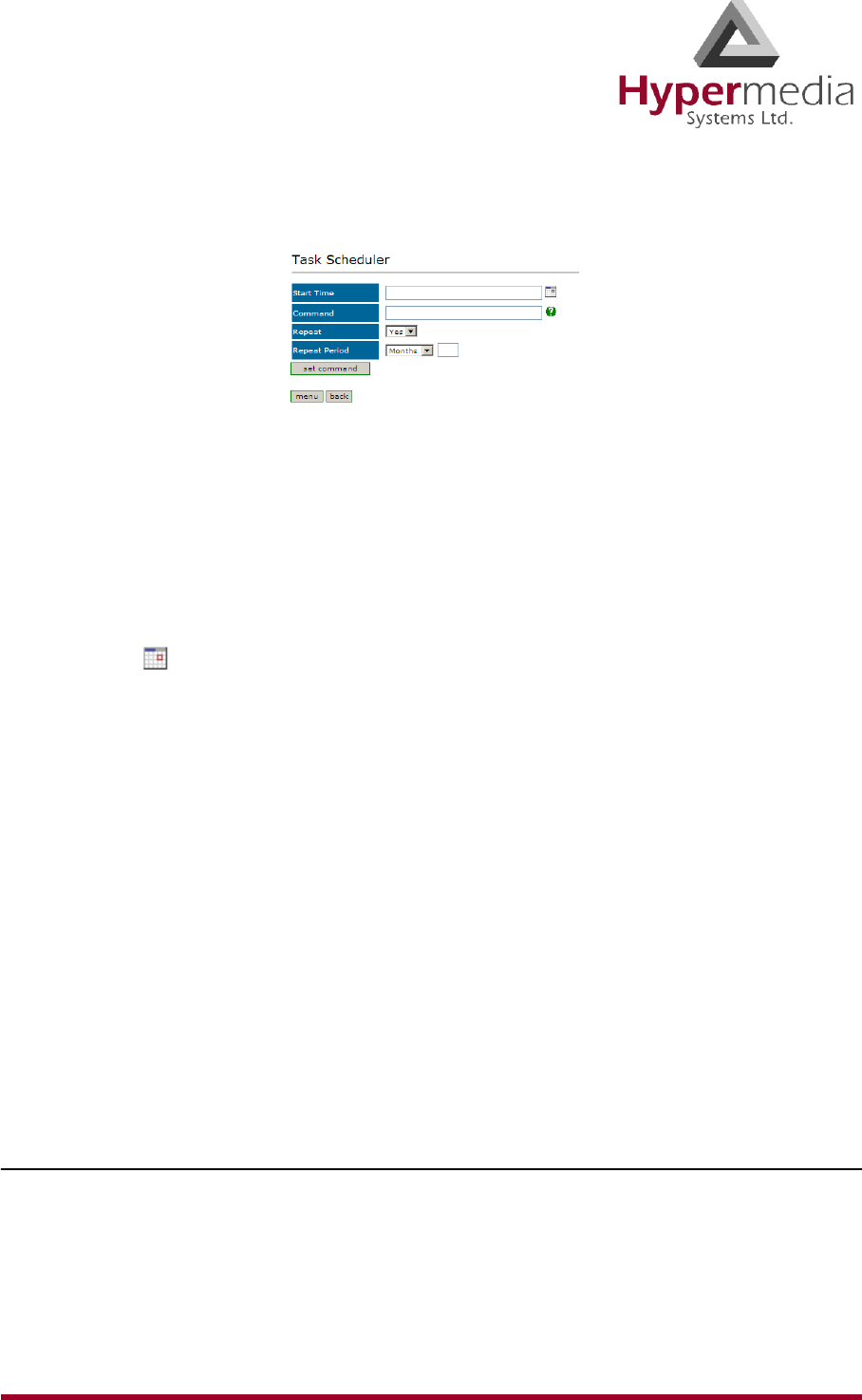
HMC Product Manual 133
Release 3.4: May 2010 Scheduler
5. Click Next. The Set Command screen, with the command syntax, is displayed.
Figure 130: Task Scheduler Set Command Screen
WARNING! Clicking menu deletes the new task. The table of schedules tasks is
redisplayed.
6. Configure the task’s schedule:
a. Click (calendar icon). A calendar opens in a new browser tab.
Note: First, set the time. As soon as you click the date, the browser tab closes and the date
and time are entered into the Start Time field.
b. Enter the time that the command will start.
c. Enter the date that the command will start. When you click the date, the browser tab
closes and the date and time are entered into the Start Time field.
d. From the Repeat drop-down menu, select either Yes or No.
e. If the task is configured to repeat, select a Repeat Period. The Repeat Period can be
either months, days, hours, or minutes.
7. Click Set Command. The new Task is displayed in the Task Scheduler screen.
8. Click Upload Schedule. The Server activates the schedule according to the defined dates
and times.
VoIP Channels
Use the VoIP Channels task to block, open, or clear VoIP channels at a specific time.
1. From the HMC navigation pane, expand the Manage branch.
2. Click the Scheduler sub-branch. The Task Scheduler screen is displayed.
3. From the Add New Command dropdown menu, select VoIP Channels. The Task
Scheduler automatically advances to the next screen.
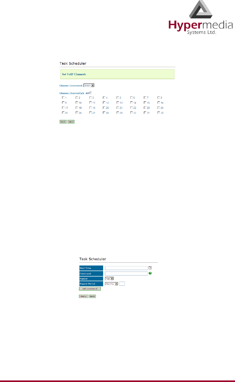
HMC Product Manual 134
Release 3.4: May 2010 Scheduler
Figure 131: Task Scheduler Set VoIP Channels Screen
4. From the Choose Command dropdown menu, select either:
Block
Disables the selected channels.
Open
Enables the selected channels.
Clear
Disconnects all current calls on the selected channels.
5. Select the checkboxes of the channels that the task will be applied to.
Note: Select All to apply the task to all the channels.
6. Click Next. The Set Command screen, with the command syntax, is displayed.
Figure 132: Task Scheduler Set Command Screen
WARNING! Clicking menu deletes the new task. The table of schedules tasks is
redisplayed.
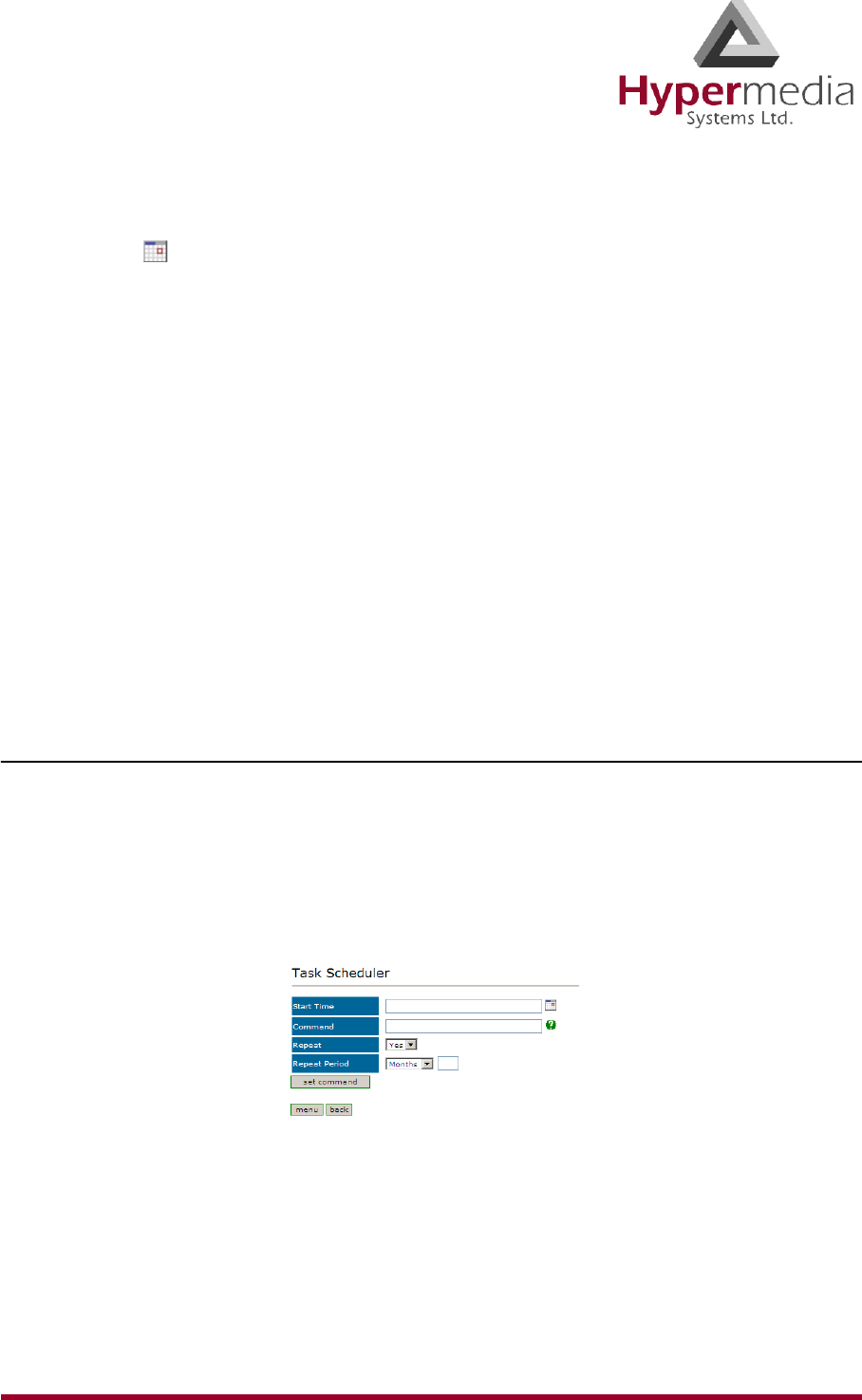
HMC Product Manual 135
Release 3.4: May 2010 Scheduler
7. Configure the task’s schedule:
a. Click (calendar icon). A calendar opens in a new browser tab.
Note: First, set the time. As soon as you click the date, the browser tab closes and the date
and time are entered into the Start Time field.
b. Enter the time that the command will start.
c. Enter the date that the command will start. When you click the date, the browser tab
closes and the date and time are entered into the Start Time field.
d. From the Repeat drop-down menu, select either Yes or No.
e. If the task is configured to repeat, select a Repeat Period. The Repeat Period can be
either months, days, hours, or minutes.
8. Click Set Command. The new Task is displayed in the Task Scheduler screen.
9. Click Upload Schedule. The Server activates the schedule according to the defined dates
and times.
Manual Command
Use the Manual Command task to customize a task and its schedule.
1. From the HMC navigation pane, expand the Manage branch.
2. Click the Scheduler sub-branch. The Task Scheduler screen is displayed.
3. From the Add New Command dropdown menu, select Manual Command. The Task
Scheduler automatically advances to the next screen.
Figure 133: Task Scheduler Manual Command Screen
WARNING! Clicking menu deletes the new task. The table of schedules tasks is
redisplayed.

HMC Product Manual 136
Release 3.4: May 2010 Scheduler
4. Configure the task and its schedule:
a. Click (calendar icon). A calendar opens in a new browser tab.
Note: First, set the time. As soon as you click the date, the browser tab closes and the date
and time are entered into the Start Time field.
b. Enter the time that the command will start.
c. Enter the date that the command will start. When you click the date, the browser tab
closes and the date and time are entered into the Start Time field.
d. Enter the command. For help with command syntax, click .
e. From the Repeat drop-down menu, select either Yes or No.
f. If the task is configured to repeat, select a Repeat Period. The Repeat Period can be
either months, days, hours, or minutes.
5. Click Set Command. The new Task is displayed in the Task Scheduler screen.
6. Click Upload Schedule. The Server activates the schedule according to the defined dates
and times.
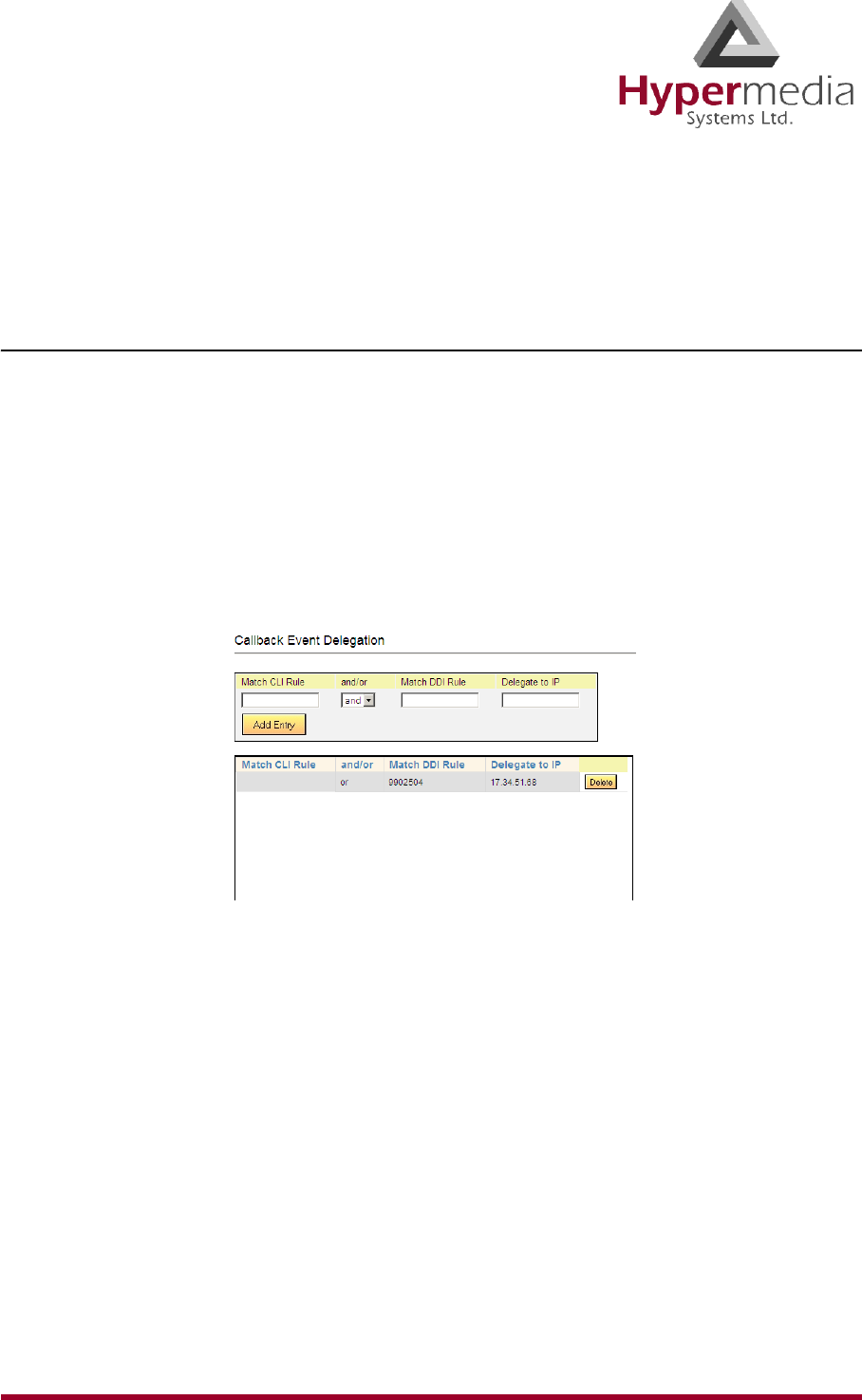
HMC Product Manual 137
Release 3.4: May 2010 Callback
Callback
Hypermedia Gateway Callback includes tools which expand the feature’s flexibility.
Remote Delegation
Use Remote Delegation to forward a Callback trigger to another Hypermedia Gateway. After
the receiving Hypermedia Gateway authenticates the calling party, it forwards the Callback
trigger to another Gateway, that is, it delegates the Callback request. The remote Hypermedia
Gateway performs the Callback.
To configure Remote Delegation:
1. From the HMC navigation pane, expand the Manage branch and the Callback sub-
branch.
2. Click the Remote Delegation sub-branch. The Remote Delegation screen is displayed.
Figure 134: HMC Remote Delegation Screen
3. In the Match CLI Rule field, enter the user’s phone number. When the Gateway identi-
fies the number, it delegates the call to the remote Gateway.
4. Select either and or or.
5. In the Match DDI Rule field, enter the PBX extension. When a user dials the extension
number, the Gateway receives the Callback request and delegates it to the remote
Gateway.
6. In the Delegate to IP field, enter the IP address of the Hypermedia Gateway which
receives the delegated Callback requests.
7. Click Add Entry. The new entry is added to the Callback Event Delegation table.
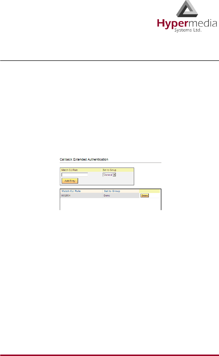
HMC Product Manual 138
Release 3.4: May 2010 Callback
Ext. Authentication
Use Extended Authentication to reserve Callback resources for a specific user or Group of
users.
Note: This feature operates independent of the authentication registered on the User List
(see “User List” on page 123).
To configure Extended Authentication:
1. From the HMC navigation pane, expand the Manage branch and the Callback sub-
branch.
2. Click the Ext. Authentication sub-branch. The Extended Authentication screen is dis-
played.
Figure 135: HMC Extended Authentication Screen
3. In the Match CLI Rule field, enter the user’s phone number. When the Gateway identi-
fies the number, it associates the Callback request with reserved resources.
4. From the Set to Group drop-down menu, select a Group. These are the Groups that are
defined on the VPN Groups screen. Resources are reserved for members of the Group.
5. Click Add Entry. The new entry is added to the Callback Extended Authentication table.
Note: For Extended Authentication to work, a resource has to be allocated to Callback and
then assigned to the specific VPN Group.

HMC Product Manual 139
Release 3.4: May 2010
Chapter 7
CALLBACK and CALLTHROUGH
This section provides an overview of Callback and Callthrough and documents Best Practices
for configuring each.
Note: A best-practice is a technique or methodology that, through experience and research,
has been proven to efficiently and reliably lead to the desired result.
A Hypermedia Gateway includes many additional Callback and Callthrough parameters that
are used in specific settings and are not related to Best Practices. They are documented else-
where in this manual.
This section includes:
• “Callback Overview” on page 140
• “Callback Best Practice” on page 141
• “Callthrough Overview” on page 149
• “Callthrough Best Practice” on page 150
• “CB/CT CDRs” on page 154
Note: Callback and Callthrough belong to the Hypersavings Package and require a separate
license.
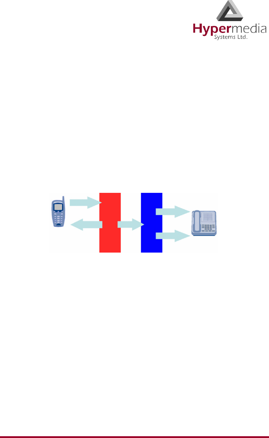
HMC Product Manual 140
Release 3.4: May 2010 Callback Overview
Callback Overview
A Hypermedia Gateway can be configured to authorize an incoming call, disconnect the
incoming call, and then call-back the User. This feature is called Callback and is designed, for
example, for users who are making calls from an international location to their home country.
A Callback is initiated by a trigger. The trigger can be either a phone call, an SMS message, or
a message sent via the Hypermedia Web-based Callback dialer. The trigger initiates the fol-
lowing sequence:
a. the Gateway identifies the user as a user authorized to activate Callback
b. the Gateway disconnects the call
c. the Gateway searches for an available Callback Resource
d. the Gateway calls-back the User
e. optionally, the Gateway calls the destination party.
Figure 136: Callback Triggers Diagram
Note: If several Resources are dedicated to Callback, incoming calls are automatically
routed to the first available Resource.
The most common type of Callback Trigger is a dedicated channel, that is, the Resource must
be linked to itself.
Once connected, the user can then make unlimited consecutive outbound calls by double-
keying the pound/hash key (#, #).
Callback is available using cellular cards and PRI cards, but not VoIP cards.
Trigger
1st Leg 2nd Leg
Extensions
PSTN
HyperGateway
Office PBX

HMC Product Manual 141
Release 3.4: May 2010 Callback Best Practice
Callback Best Practice
The best-practice order for configuring Callback is:
1. Determine a trigger strategy.
2. Allocate the Trigger resource.
3. Allocate the Callback resource.
4. Optionally, require PIN code authorization.
5. Authorize the user.
6. Inform users.
Determine a Trigger Strategy
Not all triggers are supported by all PSTNs. The Hypermedia Gateway supports the following
types of triggers:
•CLI trigger
The CLI Callback service is used in countries where CLI (calling line identification
or caller ID) is available through the PSTN. The user dials a Trigger resource. The
Hypermedia Gateway identifies the CLI and begins the Callback process.
• Fixed trigger
With a fixed trigger, the Hypermedia Gateway does not authorize the user. Users call
a pre-allocated corporate telephone number that has been allocated as a Trigger
resource. This number is called a DDI (Direct Dial-in) number. The Hypermedia
Gateway is configured to call back a specific phone number each time the DDI is
triggered.
• SMS trigger (cellular resources only)
Users also can initiate a Callback by sending an SMS message. The text of the SMS
must include the destination phone number the Hypermedia Gateway must call.
• Web-based Callback Dialer
This feature is currently being developed. Contact Technical Support for information
about using a browser-based visual Callback Dialer to dial a destination number and
receive a callback call on a registered callback number.Allocate the Trigger Resource
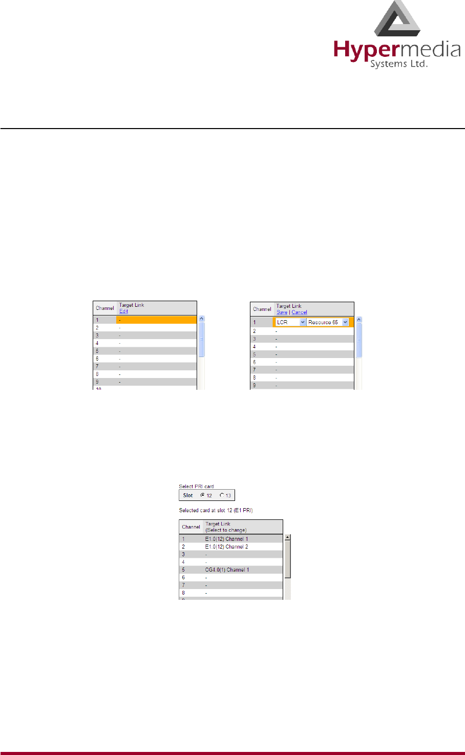
HMC Product Manual 142
Release 3.4: May 2010 Callback Best Practice
Allocate the Trigger Resource
The most common type of Callback Trigger is a dedicated channel, that is, the Resource must
first be linked to itself and then allocated as a trigger.
1. Link the Resource to itself:
a. From the HMC navigation pane, click the Media Connections sub-branch of either
the Cellular Cards, PRI Cards, or LCR. The Media Matrix is displayed.
b. If more than one slot is displayed, select a specific card. The Media Matrix of that
card is displayed.
c. Click within a Resource row. The row turns yellow.
d. Click Edit. The row becomes configurable.
Figure 137: Media Matrix Row when Configurable
e. From the first dropdown list, allocate this card to itself by selecting the same card.
f. From the second dropdown list, assign this channel to itself by selecting the same
channel.
Figure 138: Assigning a Target Link
g. Click Save. The configuration dropdown boxes are hidden.
h. Click Apply Settings and wait for Configuration Saved to be displayed.
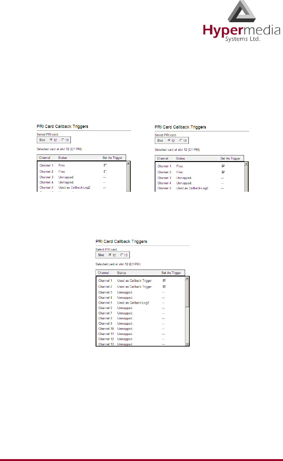
HMC Product Manual 143
Release 3.4: May 2010 Callback Best Practice
2. Allocate the Resource to Trigger:
a. Select one of the Triggers sub-branches (either the PRI Cards > Callback Triggers
sub-branch or Cellular Cards > Callbacks > Call Triggers). The Callback Triggers
screen is displayed.
b. Select the checkboxes of the Resources that are allocated as Callback Triggers.
Figure 139: Allocating Resources to Callback Triggers
c. Click Apply Settings and wait for Configuration Saved to be displayed. The
allocation is confirmed in the Callback Trigger table.
Figure 140: Callback Trigger Table
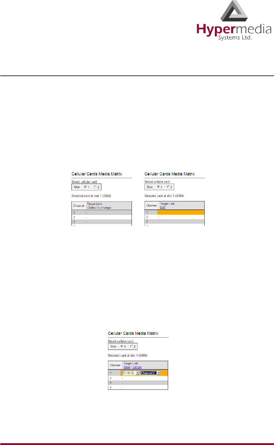
HMC Product Manual 144
Release 3.4: May 2010 Callback Best Practice
Allocate the Callback Resource
Allocating a Callback Resources requires, first, linking it, and then setting it as 1st Leg.
1. Link the Resource to another resource:
a. From the HMC navigation pane, click the Media Connections sub-branch of either
the Cellular Cards, PRI Cards, or LCR. The Media Matrix is displayed.
b. If more than one slot is displayed, select a specific card. The Media Matrix of that
card is displayed.
c. Click within a Resource row. The row turns yellow.
d. Click Edit. The row becomes configurable.
Figure 141: Media Matrix Row when Configurable
e. From the first dropdown list, allocate this card to a target card by selecting the second
card.
Note: If all of the second card’s channels are already allocated, the message “Fully
allocated” appears.
f. From the second dropdown list, assign this Resource (channel) to a specific Resource
(channel) on the target card.
Figure 142: Assigning a Target Link
g. Click Save. The configuration dropdown boxes are hidden.
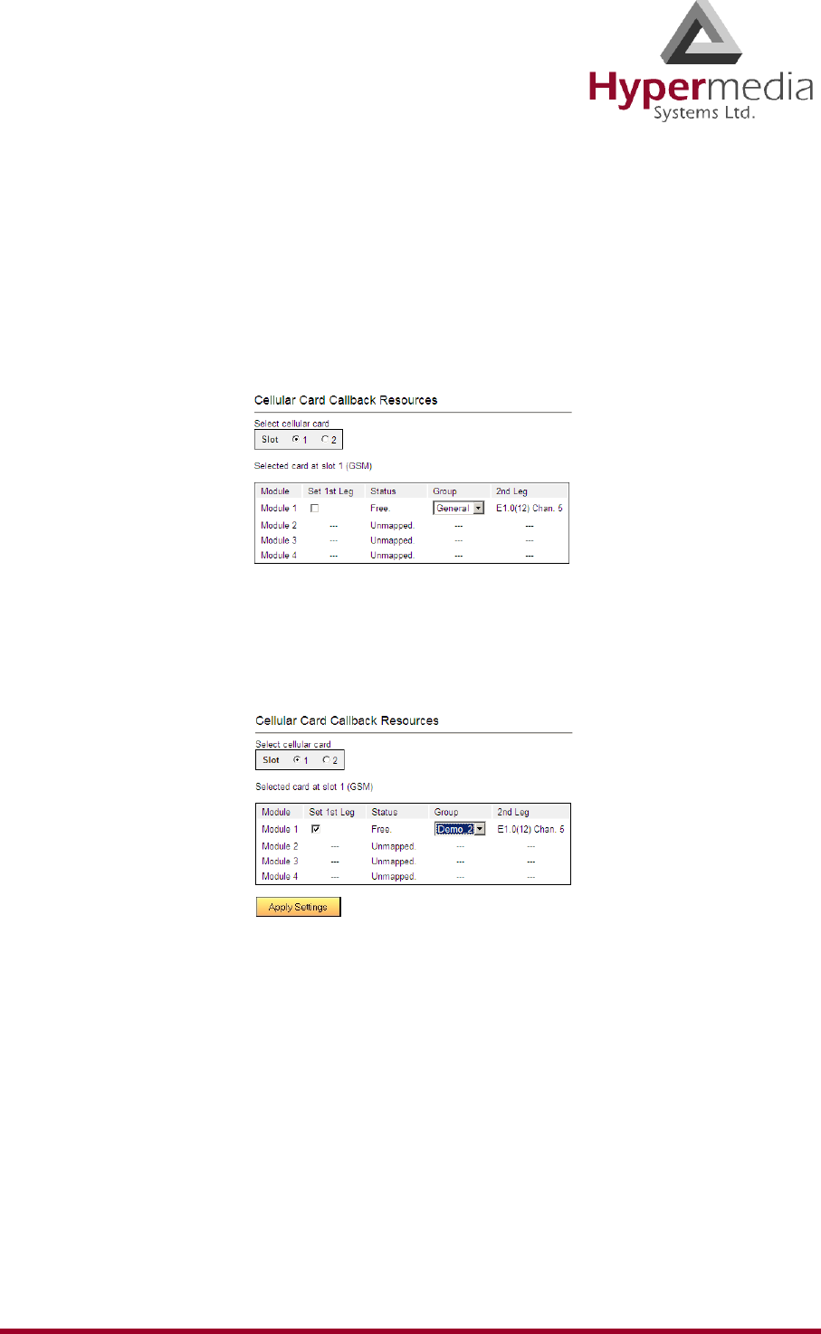
HMC Product Manual 145
Release 3.4: May 2010 Callback Best Practice
h. Optionally, repeat the process for additional channels and other media types.
i. Click Apply Settings and wait for Configuration Saved to be displayed.
2. Set the Resource as 1st Leg:
a. Select one of the Callback Resources sub-branches (either the PRI Cards > Callbacks
sub-branch or Cellular Cards > Callbacks > Resources). The Callback Resources
screen is displayed.
Figure 143: Callback Resources Screen
b. Select the checkbox of the Resources that is allocated as Callback 1st Leg.
c. Select the Group that is authorized to access this Resource.
Figure 144: Selecting the Authorized Group
d. Click Apply Settings and wait for Configuration Saved to be displayed. The
allocation is confirmed in the Callback Resources table of both legs.
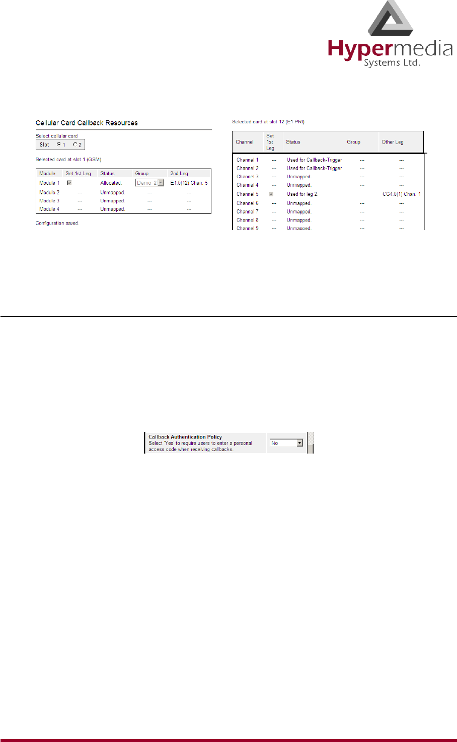
HMC Product Manual 146
Release 3.4: May 2010 Callback Best Practice
Figure 145: Confirmation of Allocation of Resource to Callback
Optionally, Require PIN Code Authorization
Hypermedia Gateways can be configured to require that users enter a Personal Identification
Number (PIN) before receiving Callback resources.
To require PIN code authorization:
1. From the Configure branch of the HMC navigation pane, click the Call Parameters sub-
branch. The Call Configuration screen is displayed.
2. Scroll down to the Callback Authentication Policy parameter.
Figure 146: Callback Authentication Policy Parameter
3. Select either Yes or No. If Yes is selected, users are required to enter a personal access
code when receiving callbacks.
Note: Optionally, configure other Callback parameters. For documentation on the other
parameters, see “Call Parameters” on page 27.
4. Click Submit.
5. Wait for the Successfully updated message.
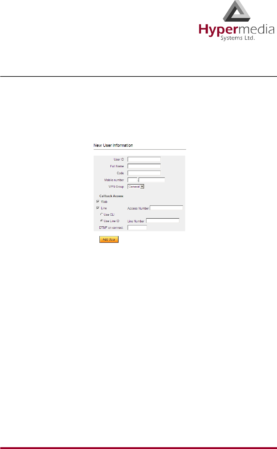
HMC Product Manual 147
Release 3.4: May 2010 Callback Best Practice
Authorize the User
Perform initial user configuration using the Add User screen. To change a user’s configura-
tion, and to delete a user, use the User List screen.
To add a new user:
1. From the HMC navigation pane, expand the Manage branch.
2. Click the Add User sub-branch. The New User Information screen is displayed.
Figure 147: New User Information Screen
3. Enter the following user information:
User ID
This can be any string. The information reappears in the All Users table.
Full Name
This information reappears in the All Users table.
Code
Any random string of numbers and letters.
Mobile Number
Enter the user’s mobile device number.
VPN Group
From the dropdown menu, assign the user to a VPN Group.
4. Define the users Callback access:
Web
This feature is currently being developed. Contact Technical Support for information
about using a browser-based visual Callback Dialer to dial a destination number and
receive a callback call on a registered callback number.

HMC Product Manual 148
Release 3.4: May 2010 Callback Best Practice
Line
When selected, the user is able to trigger a Callback via a telephone call. If selected:
a. In the Access Number field, enter the phone number the user dials to access the
Hypermedia Gateway. This is the DDI number that is allocated as a trigger.
b. Select one of the following:
• Use CLI
The Hypermedia Gateway uses Caller Line Identification (CLI) to automatically
identify the phone number to be called back.
• Use Line ID
Enter the Line Number. The Hypermedia Gateway calls back the number
entered in the Line Number field.
DTMF on connect
Enter the DTMF sequence. This is a DTMF string that the Gateway will automatically
dial and which connects the user to an Automated Voice Response (AVR) system.
5. Click Add User and wait for the “User added successfully” message.
Inform Users
It is the system administrator’s responsibility to inform end-users. They need to know the DDI
numbers that allocated to Callback.

HMC Product Manual 149
Release 3.4: May 2010 Callthrough Overview
Callthrough Overview
Use Callthrough to place calls, via the Hypermedia Gateway, to external numbers. Users
receive a dial-tone from the Hypermedia Gateway and can then place calls either:
• via the PBX to a corporate extension
• to a VoIP phone number
• to a Cellular phone number
• to a PSTN phone number
A Callthrough is initiated by a call to a Resource allocated to Callthrough. The call initiates
the following sequence:
a. the Gateway searches for an available Callthrough Resource
b. the Gateway connects the call with the linked resource.
Figure 148: Callthrough Diagram
1st Leg 2nd Leg
PBX
Cellular
HyperGateway
}
VoIP
Cellular
PSTN
VoIP
PSTN
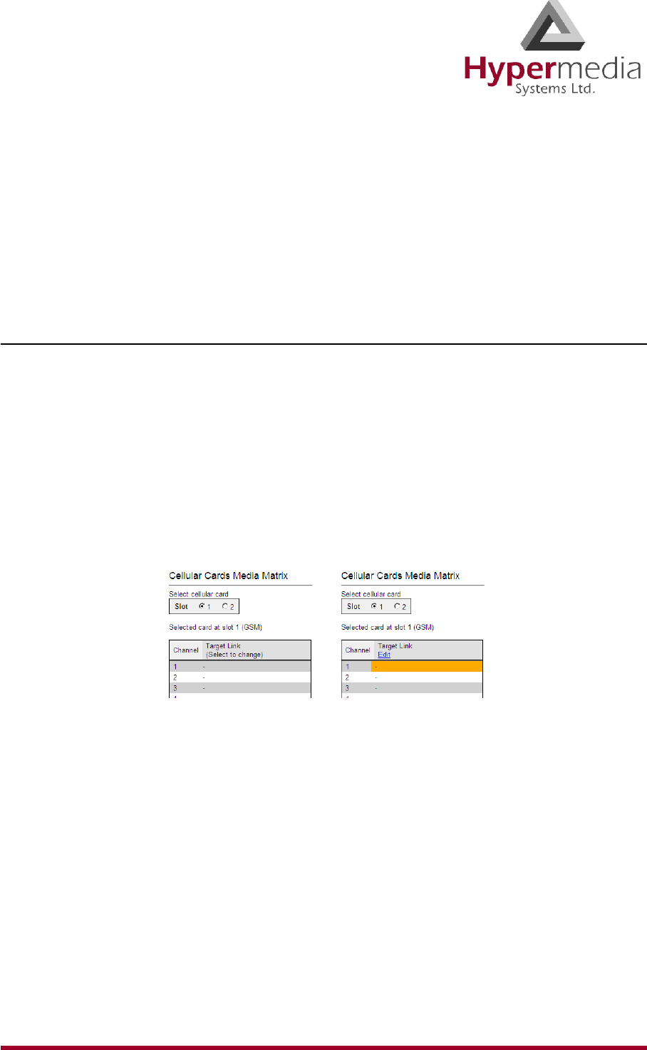
HMC Product Manual 150
Release 3.4: May 2010 Callthrough Best Practice
Callthrough Best Practice
The best-practice order for configuring Callthrough is:
1. Allocate the Callthrough resource.
2. Determine and configure a user authentication strategy.
3. Inform users.
Allocate the Callthrough Resource
Allocating a Callthrough Resources requires, first, linking it, and then setting it as 1st Leg.
1. Link the Resource to another resource:
a. From the HMC navigation pane, click the Media Connections sub-branch of either
the Cellular Cards, PRI Cards, or LCR. The Media Matrix is displayed.
b. If more than one slot is displayed, select a specific card. The Media Matrix of that
card is displayed.
c. Click within a Resource row. The row turns yellow.
d. Click Edit. The row becomes configurable.
Figure 149: Media Matrix Row when Configurable
e. From the first dropdown list, allocate this card to a target card by selecting the second
card.
Note: If all of the second card’s channels are already allocated, the message “Fully
allocated” appears.
f. From the second dropdown list, assign this Resource (channel) to a specific Resource
(channel) on the target card.
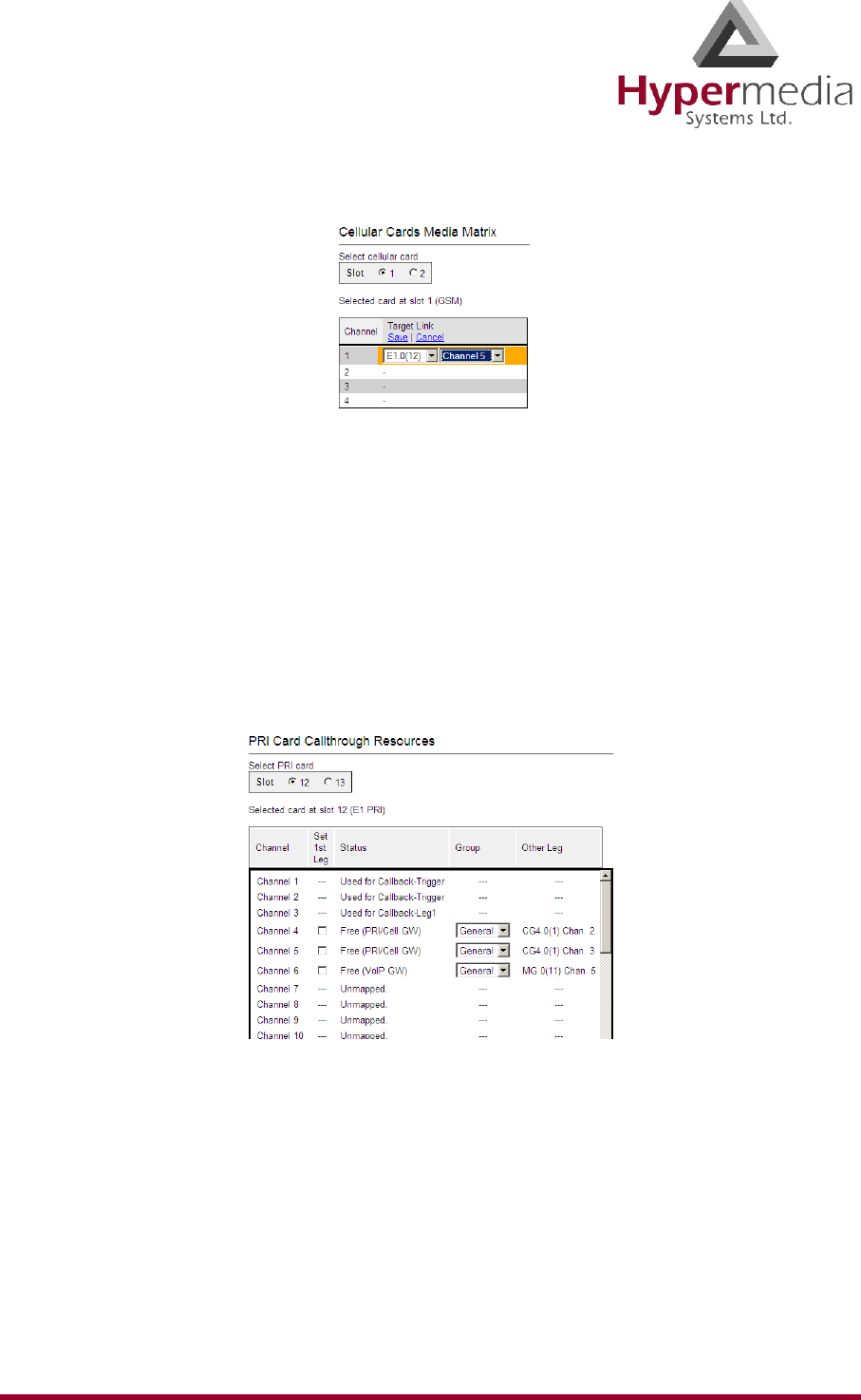
HMC Product Manual 151
Release 3.4: May 2010 Callthrough Best Practice
Figure 150: Assigning a Target Link
g. Click Save. The configuration dropdown boxes are hidden.
h. Optionally, repeat the process for additional channels and other media types.
i. Click Apply Settings and wait for Configuration Saved to be displayed.
2. Set the Resource as 1st Leg:
a. Select one of the Callthrough Resources sub-branches (either the Cellular, PRI, LCR,
or VoIP Cards > Callthroughs sub-branch). The Callthrough Resources screen is
displayed. Empty checkboxes appear beside available (Free) resources.
Figure 151: PRI Card Callthrough Resources Screen
b. Select the checkboxes of the Resources that are allocated as Callthrough 1st Leg.
c. Select the Group that is authorized to access this Resource.
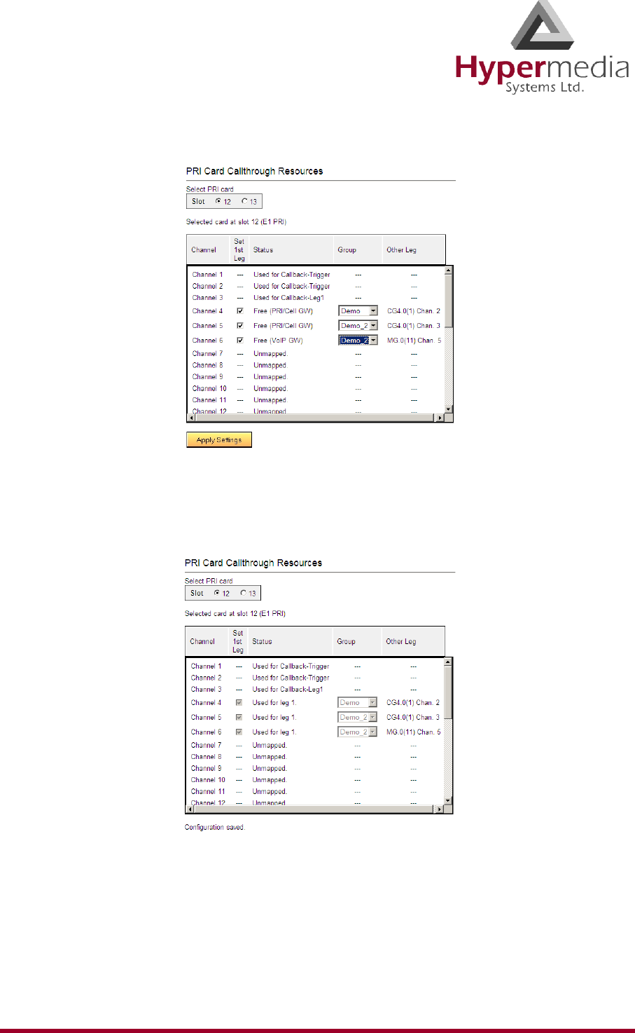
HMC Product Manual 152
Release 3.4: May 2010 Callthrough Best Practice
Figure 152: Selecting the Authorized Group
d. Click Apply Settings and wait for Configuration Saved to be displayed. The
allocation is confirmed in the Callback Resources table of both legs.
Figure 153: Confirmation of Allocation of Resource to Callback
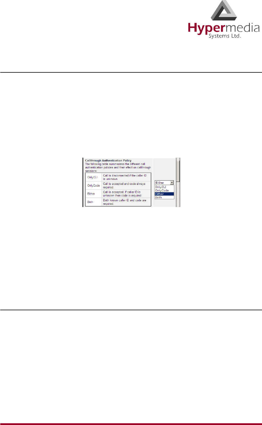
HMC Product Manual 153
Release 3.4: May 2010 Callthrough Best Practice
Determine and Configure a User Authentication Strategy
The Hypermedia Gateway can be configured to require that the Callthrough user be authorized
through a form of authentication.
To configure user authentication:
1. From the Configure branch of the HMC navigation pane, click the Call Parameters sub-
branch. The Call Configuration screen is displayed.
2. Scroll down to the Callthrough Authentication Policy parameter.
3. From the dropdown menu, select an option described in the table of authentication poli-
cies.
Figure 154: Table of Authentication Policies
Note: Optionally, configure other Callback parameters. For documentation on the other
parameters, see “Call Parameters” on page 27.
4. Click Submit.
5. Wait for the Successfully updated message.
Inform Users
It is the system administrator’s responsibility to inform end-users. They need to know the DDI
numbers that allocated to Callthrough.
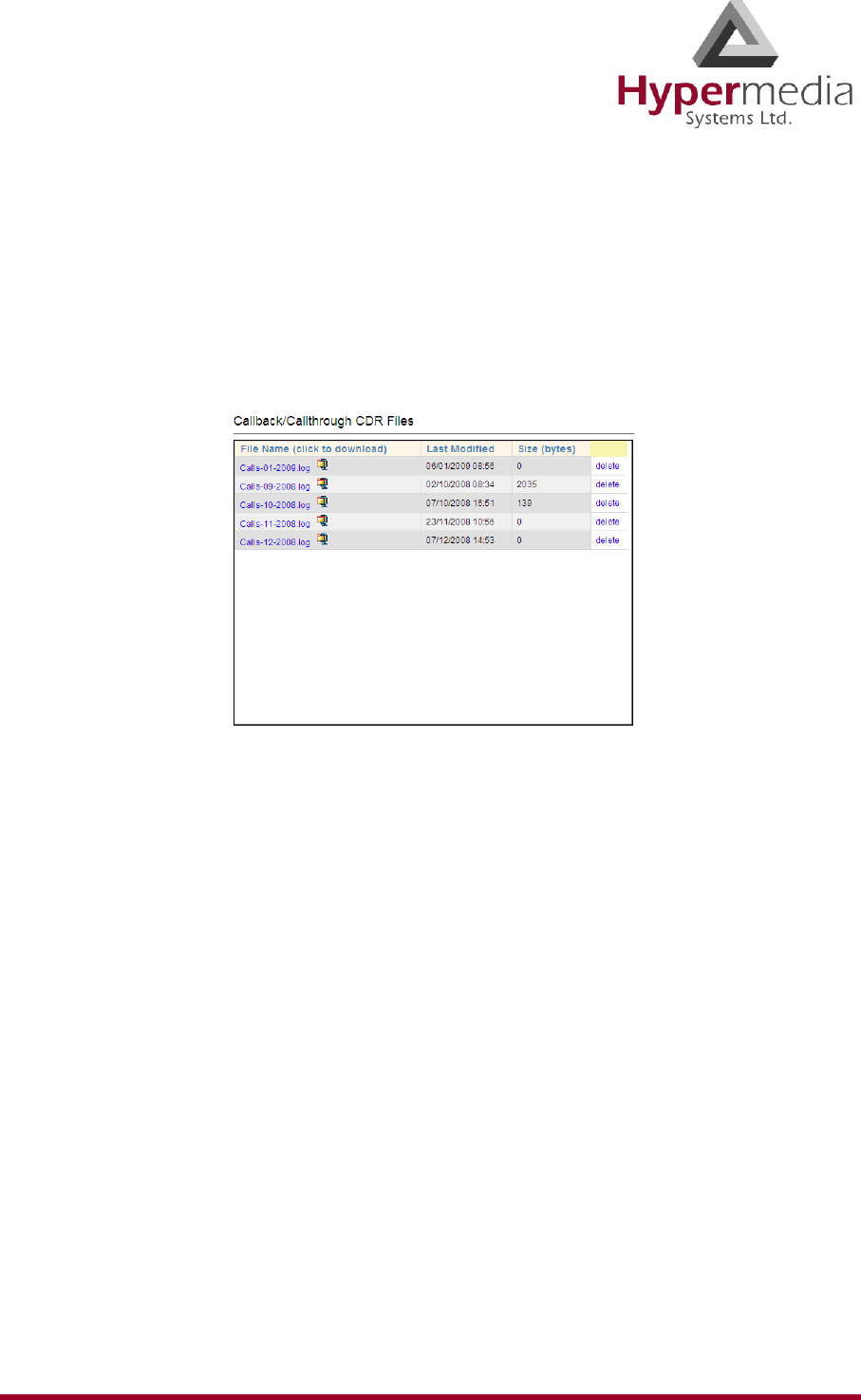
HMC Product Manual 154
Release 3.4: May 2010 CB/CT CDRs
CB/CT CDRs
To manage and download the Callback and Callthrough CDR files:
1. From the HMC navigation pane, expand the Monitor branch.
2. Expand the LCR Card sub-branch and select CB/CT CDRs. The list of CDR files is dis-
played.
Figure 155: Callback/Callthrough CDR Files Screen
3. Click a file name. The standard Windows Open dialog box is displayed.
4. Define the location where the file will be saved and click OK. The file is downloaded to
that location.
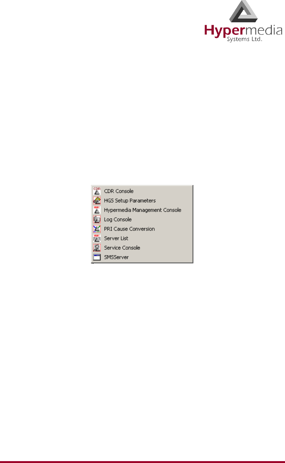
HMC Product Manual 155
Release 3.4: May 2010
Chapter 8
CONSOLE SUITE and other TOOLS
This section contains:
• The Console Suite including:
• “CDR Console” on page 156
• “Log Console” on page 157
• “Decoding Logs” on page 158
• “Service Console” on page 167
• Additional Configuration and Management Tools including:
• “HGS Setup Parameters Tool” on page 168
• “PRI Cause Conversion” on page 170
• “Hypermedia Gateway Server List” on page 172

HMC Product Manual 156
Release 3.4: May 2010 Console Suite
Console Suite
The following three consoles are installed during initial installation.
CDR Console
Use the CDR Console to download and review Call Detail Records.
Note: The CDR Console feature is relevant only to Hypermedia HG4000 Gateways.
To run the CDR Console:
1. Click the Windows Start button > All Programs.
2. From the Hypermedia program group, select CDR Console. The CDR Console logon
screen opens in the default browser.
3. Click the warning bar at the top of the screen and, from the dropdown menu, click Allow
Blocked Content. Confirm your choice by clicking Ye s at the confirmation message.
Note: To avoid recurring displays of the warning bar, from the menu bar click Tools >
Internet Options > Advanced > Allow active content to run in files on My Computer.
4. Enter your password and click Submit. The CDR Console screen is displayed.
Figure 156: CDR Console Screen
5. Click a file name. The standard Windows Open dialog box is displayed.
6. Define the location where the file will be saved and click OK. The file is downloaded to
that location.
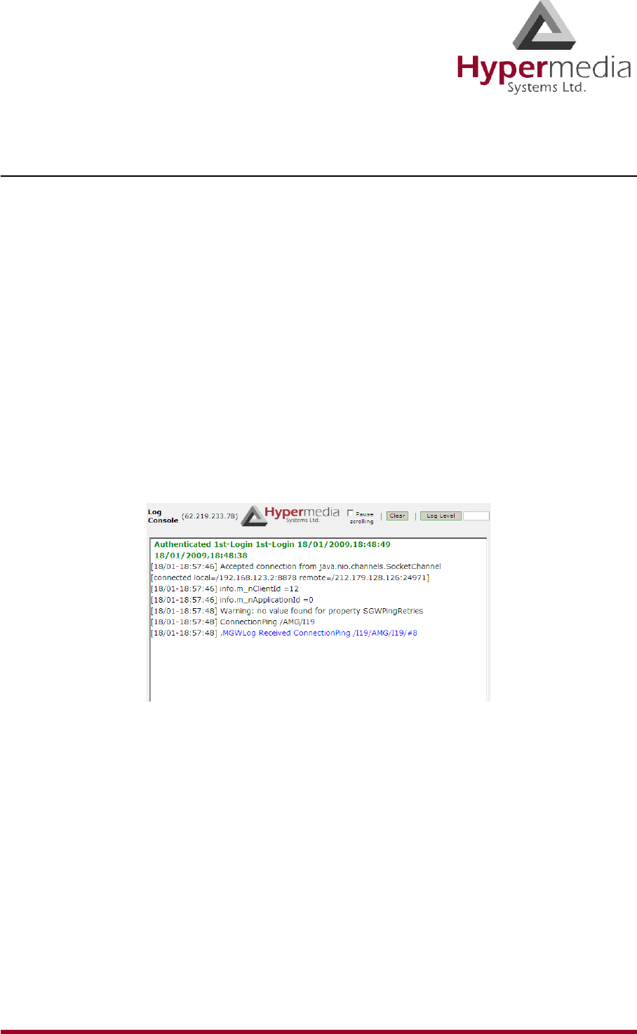
HMC Product Manual 157
Release 3.4: May 2010 Console Suite
Log Console
Use the Log Console to review the primary system log. All events and alarms are printed to
this log.
To run the Log Console:
1. Click the Windows Start button > All Programs.
2. From the Hypermedia program group, select Log Console. The Log Console logon
screen opens in the default browser.
3. Click the warning bar at the top of the screen and, from the dropdown menu, click Allow
Blocked Content. Confirm your choice by clicking Ye s at the confirmation message.
Note: To avoid recurring displays of the warning bar, from the menu bar click Tools >
Internet Options > Advanced > Allow active content to run in files on My Computer.
4. Enter your password and click Submit. The Log Console screen is displayed.
Figure 157: Log Console Screen
5. Select a log level from 1 to 10. The Log Console filters the recorded logs and displays
only the logs matching the level.

HMC Product Manual 158
Release 3.4: May 2010 Console Suite
Decoding Logs
Following are sample Logs that have been edited. Only the relevant entries remain. The
excerpted content is explained in following the Log sample.
VoIP to GSM Log
Following are excerpts from a VoIP to GSM Log.
[25/03-09:56:24.032] [debug] getRemoteSignalIP=192.168.1.67
…
[25/03-09:56:24.067] [debug] CreateIncomingSession token: 2cf9b58a-f8f3ae56-ad3c20da-
d44bfdec@192.168.1.67 remoteNumber: 30 localNumber: 0774445016 remoteIP: 192.168.1.67
…
[25/03-09:56:24.089] [debug] source DDI:0774445016 allowed DDI:^*
[25/03-09:56:24.093] [debug] FindLocalMediaResources (2cf9b58a-f8f3ae56-ad3c20da-
d44bfdec@192.168.1.67/3) LocalHwyTS: 11:0 RemoteHwyTS: 5:31 media resource: 11.0
…
[25/03-09:56:24.121] getApplication for:MG.1-VoIP
…
[25/03-09:56:24.242] [debug] provideAnswer
…
[25/03-09:56:24.302] [debug] Started media, accepting call [2cf9b58a-f8f3ae56-ad3c20da-
d44bfdec@192.168.1.67]
…
[25/03-09:57:04.233] * Received Packet: HangingUp /A24/I3/o1/R10
…
[25/03-09:57:04.380] [debug] Close (2cf9b58a-f8f3ae56-ad3c20da-d44bfdec@192.168.1.67/3) closing session
timeslot:0 handle: -1
…
[25/03-09:57:04.392] [debug] (2cf9b58a-f8f3ae56-ad3c20da-d44bfdec@192.168.1.67/3) remove media
resoruce: 11.0
…
[25/03-09:57:04.991] * Received Packet: GenericReply /#90/@2b/x0,1/I2974/G
Explanation:
1. CreateIncomingSession indicates that the HG has received an incoming VoIP call and is
attempting to establish the call.
2. In this case, SIP phone 192.168.1.67 is calling 0774445016 via the HG GSM module.
3. A unique token is produced for each call. In this case, the token is:
2cf9b58a-f8f3ae56-ad3c20da-d44bfdec
4. The HG checks connection authorization for each call before connecting the call. In this
case, the authorization is: source DDI:0774445016 allowed DDI:^*

HMC Product Manual 159
Release 3.4: May 2010 Console Suite
5. JAVA analyzes to which application the call should be connected. In this case: getAppli-
cation for:MG.1-VoIP.
6. When the call recipient answers the call, the HG prints the following to the Log:
provideAnswer.
7. Started media indicates that the HG has started streaming between both parties.
8. When one party hangs-up, the HG closes the session and removes the media resources.
GSM to VoIP Log
Following are excerpts from a GSM to VoIP Log.
[25/03-10:07:14.422] HMCServer received [ping] from 127.0.0.1/127.0.0.1:3883
…
[25/03-10:07:21.791] * Received Packet: Dialing /A24/I1031/o0/H5/S31/h11/s0/n0210/N0774445016
…
[25/03-10:07:22.114] [debug] Sending INVITE
[YWZmYjRiMjY3OGMyYzJkMGU1MjQxZDcxODkzMDBjYTY], m_tokenToSession.insert
…
[25/03-10:07:24.283] [debug] Started media, accepting call
[YWZmYjRiMjY3OGMyYzJkMGU1MjQxZDcxODkzMDBjYTY.]
[25/03-10:07:24.288] Received from MGW: [Answering /A24/I1031/x0,0/o1/#0]
…
[25/03-10:08:00.224] [debug] CloseResources
(YWZmYjRiMjY3OGMyYzJkMGU1MjQxZDcxODkzMDBjYTY./1031)
…
[25/03-10:08:00.544] updateReplyContext: no effect
Explanation:
1. CreateIncomingSession indicates that the HG has received an incoming VoIP call and is
attempting to establish the call.
2. In this case, analog phone 0774445016 is calling the SIM number 0546858579. This
causes the HG to dial the MSN Value=0210.
3. The HG extracts the related called party’s IP Address from the Phone2Net table. In our
case: 192.168.1.67.

HMC Product Manual 160
Release 3.4: May 2010 Console Suite
4. A unique token is produced for each call. In this case, the token is:
YWZmYjRiMjY3OGMyYzJkMGU1MjQxZDcxODkzMDBjYTY.
5. JAVA analyzes to which application the call should be connected. In this case: getAppli-
cation for:24.1-VoIP (24.1=CG card).
6. When the call recipient answers the call, the HG prints the following to the Log: Received
from MGW: [Answering. . .
7. Started media indicates that the HG has started streaming between both parties.
8. When one party hangs-up, the HG closes the session and removes the media resources.
Callthrough Log
Following are excerpts from a Callthrough Log.
[25/03-10:21:41.783] * Received Packet: Dialing /A24/I1032/o0/H5/S31/h5/s32/n0210/N0544331123
…
[25/03-10:21:42.327] Application:Callthrough-Leg1
…
[25/03-10:21:42.563] MGWCallthrough (1032) Authentication successfull, CLI found:0544331123
…
[25/03-10:21:45.997] [debug] OnDTMF notification: Digit=0, nHW=11, nTS.Type=0.2
…
[25/03-10:21:46.396] [debug] OnDTMF notification: Digit=7, nHW=11, nTS.Type=0.2
…
[25/03-10:21:46.757] [debug] OnDTMF notification: Digit=7, nHW=11, nTS.Type=0.2
…
[25/03-10:21:47.417] [debug] OnDTMF notification: Digit=4, nHW=11, nTS.Type=0.2
…
[25/03-10:21:47.896] [debug] OnDTMF notification: Digit=4, nHW=11, nTS.Type=0.2
…
[25/03-10:21:48.286] [debug] OnDTMF notification: Digit=4, nHW=11, nTS.Type=0.2
…
[25/03-10:21:48.796] [debug] OnDTMF notification: Digit=5, nHW=11, nTS.Type=0.2
…
[25/03-10:21:49.216] [debug] OnDTMF notification: Digit=0, nHW=11, nTS.Type=0.2
…
[25/03-10:21:49.636] [debug] OnDTMF notification: Digit=1, nHW=11, nTS.Type=0.2
…
[25/03-10:21:50.176] [debug] OnDTMF notification: Digit=6, nHW=11, nTS.Type=0.2
…
[25/03-10:21:53.339] Sending: [Dialing /A24/x0,0/I0/o0/H5/S31/h5/s32/N0544331123/n0774445016], Client
ID:11
…

HMC Product Manual 161
Release 3.4: May 2010 Console Suite
[25/03-10:21:57.688] MGWCallthrough (1032) Leg2 event [SysAlerting /A24/I0/o1]
…
[25/03-10:22:09.470] Sending: [.MGWRequest /AMG/I888531/*resCloseChannel/H11/S0], Client ID:8
…
[25/03-10:22:20.969] ConnectionPing /AMG/I56/S1
Explanation:
Callthrough works as follows. The User dials the SIM number. The SIM is recognized as a
the register user and the HG sends the user a dial tone. The User can dial the destination
number. HG successfully establishes the call between both parties.
1. An external cellular phone number (in our case: 0544331123) dials to the SIM number.
2. Application: Callthrough-Leg1 indicates that the HG has established the connection
between the authorized user and Leg1.
3. Authentication successful, CLI found:0544331123 indicates that the HG has checked user
authentication.
4. The HG matches between the originating user (CLI and/or PIN Code) and the predefined
registered user.
5. After the HG assumes the correct user authentication, the User gets a dial tone from the
HG.
6. The User can dial the destination number by sending each digit of the destination number
using DTMF. In our case, that is 0774445016.
7. The HG dials to the destination called party (0774445016) and connects between Leg1
and Leg2. This is indicated by: MGWCallthrough (1032) Leg2 event [SysAlerting . . .
8. When one party hangs-up the call, the HG Closes Resources and removes media
resources.
CallBack Log
Following are excerpts from a Callthrough Log.
[26/03-10:21:01.422] ConnectionPing /AMG/I16/S1
…
[26/03-10:21:17.647] * Received Packet: Dialing /A24/I1048/o0/H5/S31/h5/s31/n0210/N0544331123
…
[26/03-10:21:17.660] getApplication for:24.1-Callback-Trigger
…
[26/03-10:21:25.824] Error: no users defined for DDI 0210,cheking CLI
[26/03-10:21:25.826] Looking up CLI: 0544331123
[25/03-10:21:42.846] Authentication successfull, CLI found:0544331123
[26/03-10:21:25.862] Creating session: Code=[0602], UserId=[udi2], AccessNum=[], EventSource=[null]

HMC Product Manual 162
Release 3.4: May 2010 Console Suite
[26/03-10:21:25.866] Sending: [Dialing /A24/x0,0/I0/o0/H5/S33/h5/s32/N/n0544331123], Client ID:10
…
[26/03-10:21:26.041] MGWCallback (0) Leg1 event [DialAck /A24/I0/o1]
…
[26/03-10:21:36.752] playDialTone 0 5.32
…
[26/03-10:21:39.113] [debug] OnDTMF /c11.0/d0/t438010
…
[26/03-10:21:41.082] [debug] OnDTMF /c11.0/d7/t1770
…
[26/03-10:21:41.812] [debug] OnDTMF /c11.0/d7/t510
…
[26/03-10:21:43.712] [debug] OnDTMF /c11.0/d4/t1680
…
[26/03-10:21:44.233] [debug] OnDTMF /c11.0/d4/t330
…
[26/03-10:21:44.892] [debug] OnDTMF /c11.0/d4/t360
…
[26/03-10:21:45.442] [debug] OnDTMF /c11.0/d5/t330
…
[26/03-10:21:46.023] [debug] OnDTMF /c11.0/d0/t330
…
[26/03-10:21:46.632] [debug] OnDTMF /c11.0/d1/t420
…
[26/03-10:21:47.213] [debug] OnDTMF /c11.0/d6/t330
…
[26/03-10:21:50.365] Sending: [Dialing /A24/x0,0/I1/o0/H5/S32/h5/s33/N/n0774445016], Client ID:10
…
[26/03-10:22:20.336] HMCServer received [ping] from 127.0.0.1/127.0.0.1:4043
Explanation:
Callback works as follows. SIM 1 is defined to ‘listen’ for an incoming call from a registered
user. SIM 2 is defined as LEG 1 and calls back the registered user and cross-connects with
SIM 3. SIM 3 is defined as LEG 2 and calls to the destination party and cross connects with
SIM 2.
1. In this case, the registered user 0544331123 is calling to the number of SIM1.
2. The HG answers the call, starts its callback engine—indicated by: getApplication
for:24.1-Callback-Trigger—and hangs up the user’s line.
Note: The HG always prints the following error message: “Error: no users defined for DDI
0210, checking CLI” Ignore this message.
3. The HG checks user authentication. Successful authentication is indicated by: Authenti-
cation successful, CLI found:0544331123.

HMC Product Manual 163
Release 3.4: May 2010 Console Suite
4. The HG matches the originating user (CLI and/or PIN Code) to the predefined registered
user.
5. After HG assumes a correct user authentication, the HG redials to the registered user.
This is indicated by: MGWCallback (0) Leg1 event [DialAck.
6. After the User answers, the HG plays a dial tone. This is indicated by: playDialTone.
7. The User can dial the desired destination called party by sending each digit of the destina-
tion called party number using DTMF: 0774445016.
8. When one party hangs-up the call, the HG starts to Close Resources and removes media
resources.
SMS Callback Log
Following are excerpts from a SMS Callback Log.
[26/03-10:39:40.805] HMCServer received [ping] from 127.0.0.1/127.0.0.1:4043
…
SMSRawCallback /A24/z/I1050/r1/N"+972544331123"/i0/G"0774445016"
…
[26/03-10:39:44.391] Adding message [SMSRawCallback /A24/z/I1050/r1/N"+972544331123"/i0/
G"0774445016"] to eventQueue for Client -1 Application ID 0
…
[26/03-10:39:47.459] Creating session: Code=[0602], UserId=[udi2], AccessNum=[], EventSource=[/tSMS/
A24/r1]
…
[26/03-10:39:47.680] MGWCallback (4) Leg1 event [DialAck /A24/I4/o1]
…
[26/03-10:39:59.131] MGWCallback (4) Leg2 event [DialAck /A24/I5/o1]
…
[26/03-10:40:44.917] * Received Packet: Ack /A2b/x0,1/I32
Explanation
SMS Callback works as follows. SIM 1 is defined to ‘listen’ for an incoming SMS from a reg-
istered user. SIM 2 is defined as LEG 1 and calls back the registered user and cross-connects
with SIM 3. SIM 3 is defined as LEG 2 and calls to the destination party and cross connects
with SIM 2.
1. In this case the registered user 0544331123 is sending an SMS message to the number of
SIM1. The SMS message contains the destination number.
2. The HG receives the SMS and starting its SMS callback engine. This is indicated by:
Adding message [SMSRawCallback . . .

HMC Product Manual 164
Release 3.4: May 2010 Console Suite
3. The HG checks user authentication. Successful authentication is indicated by: Authenti-
cation successful, CLI found:0544331123.
4. The HG matches the originating user (CLI and/or PIN Code) to the predefined registered
user.
5. After HG assumes a correct user authentication, the HG redials to the registered user.
This is indicated by: MGWCallback (4) Leg1 event [DialAck.
6. The HG calls the destination called party (Leg2) and connects it to Leg 1. This is indi-
cated by: MGWCallback (4) Leg2 event [DialAck /A24/I5/o1
7. When one party hangs-up the call, the HG starts to Close Resources and removes media
resources.
LCR Log
Following are excerpts from an LCR Log.
[26/03-10:52:16.490] [debug] getRemoteSignalIP=192.168.1.70
…
[26/03-10:52:16.516] [debug] CreateIncomingSession token: 5ea9f5a3-6193c5d4-52634512-
50c08bcf@192.168.1.70 remoteNumber: 8888 localNumber: 750 remoteIP: 192.168.1.70
…
[26/03-10:52:16.534] [debug] Number is not in BlockedDDIs list
[26/03-10:52:16.537] [debug] source DDI:750 allowed DDI:^*
[26/03-10:52:16.541] [debug] FindLocalMediaResources (5ea9f5a3-6193c5d4-52634512-
50c08bcf@192.168.1.70/4) LocalHwyTS: 11:1 RemoteHwyTS: 12:2 media resource: 11.1
…
[26/03-10:52:46.353] [debug] onReadyToSend replaced h_CallID with
[OGNhOTYwODA4MTZlNzQzZTM0ZTkzNDYyNzUwMjEzZTA
Explanation:
1. In this case, the originating party, 8888@192.168.1.70, is calling to the destination party,
750@192.168.1.67.
2. CreateIncomingSession indicates that a call is coming from (192.168.1.70) VoIP and the
HG is starting to establish the call.
3. The originating party dials the digits: 750. The HG checks that this number is not in the
BlockedDDIs list.
4. FindLocalMediaResources indicates that the HG is preparing to allocate local recourses.
5. In this case, the HG has been configured to have two uppermost LCR media connections
at the top of the VoIP Media Matrix. As a result, every incoming VoIP call to the VoIP
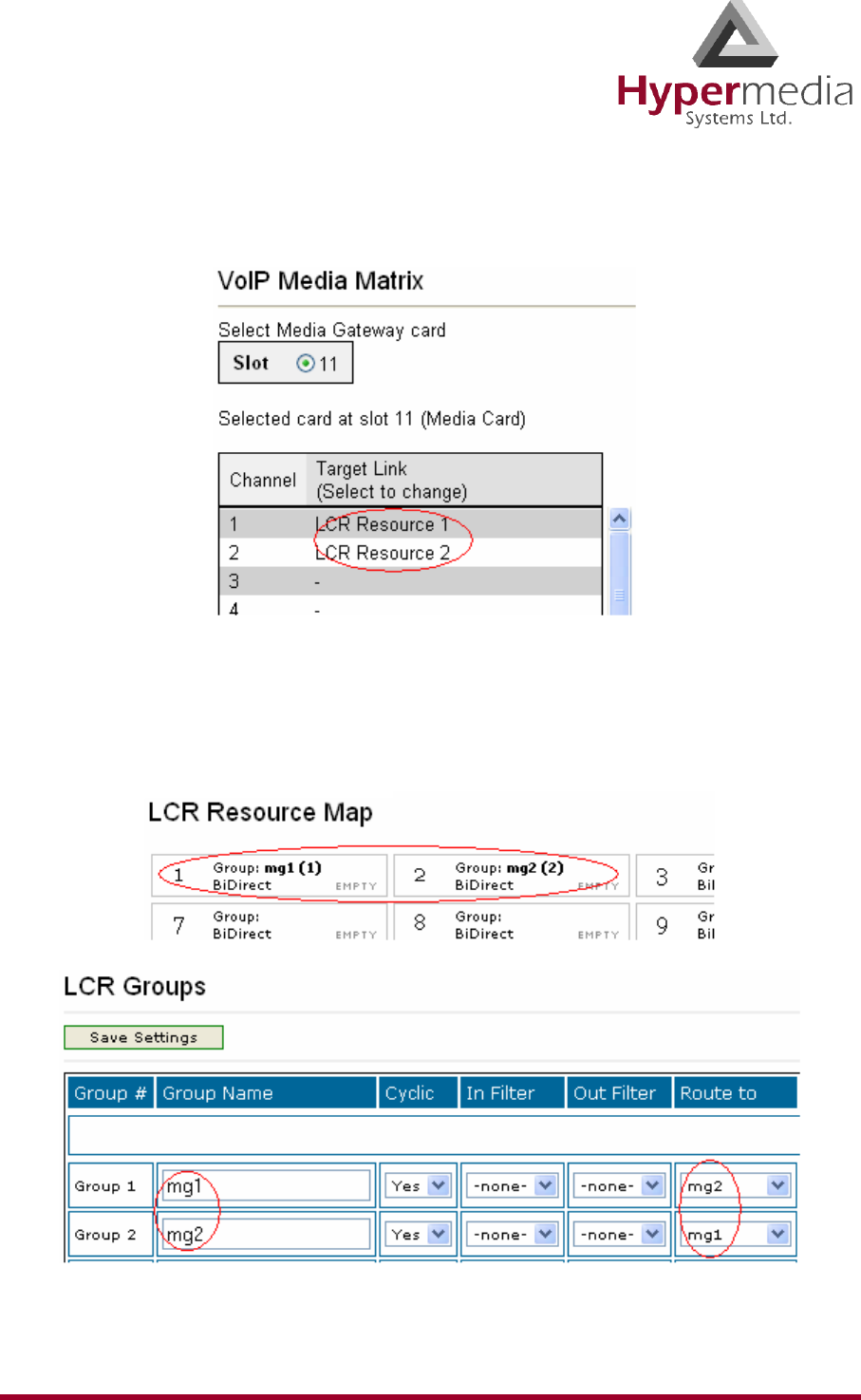
HMC Product Manual 165
Release 3.4: May 2010 Console Suite
Media Matrix will be forwarded to LCR resources. In our case, the incoming call
(192.168.1.70) is forwarded to LCR.
6. As a regular LCR configuration it was separated for two groups - incoming and termi-
nating:
• 1st LCR Group accepts the incoming VoIP call from 192.168.1.70.
• 2nd LCR Group moves the incoming VoIP call to the terminating LCR channel.
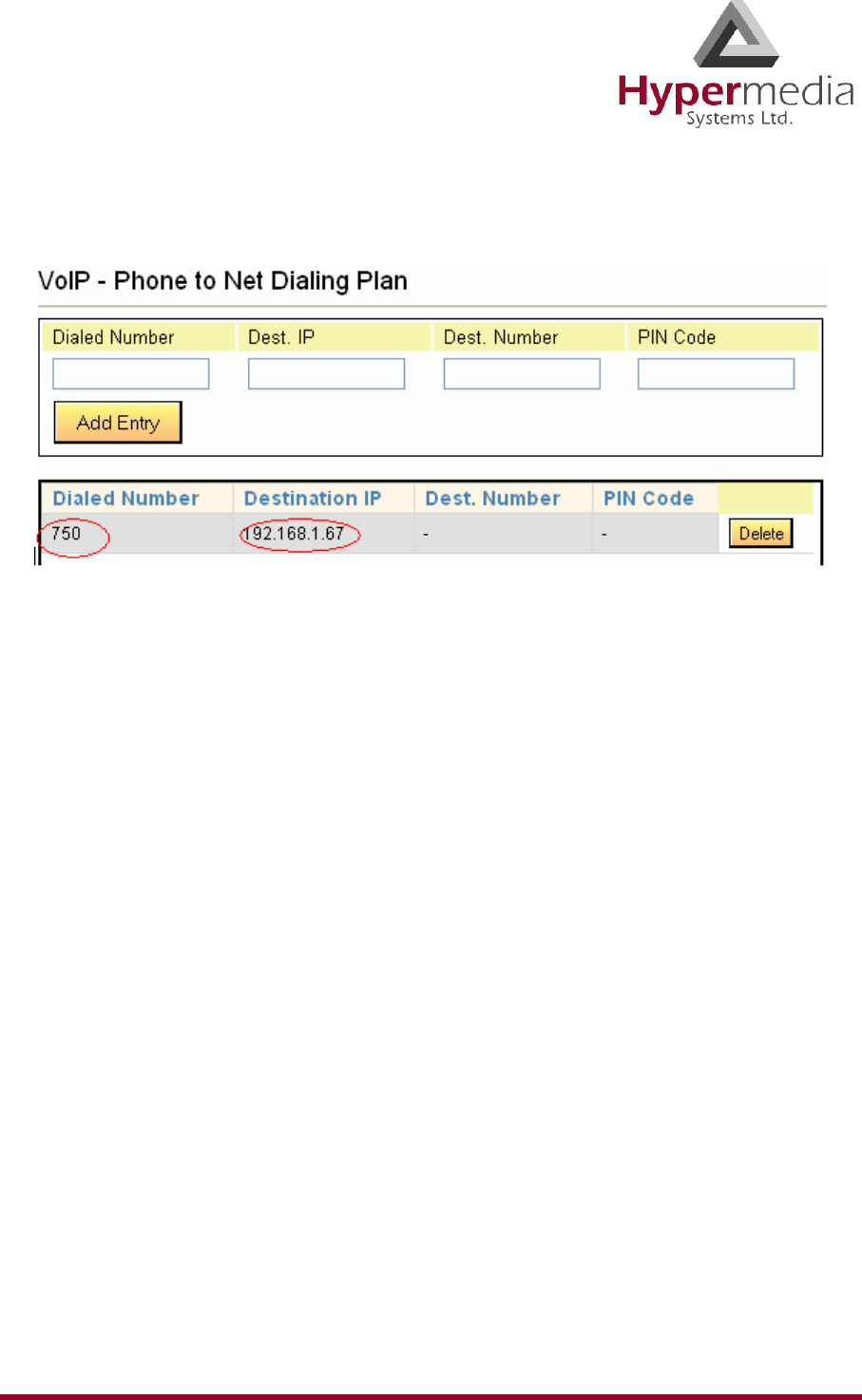
HMC Product Manual 166
Release 3.4: May 2010 Console Suite
7. In order to make the connection between the originating party and destination party, the
HG was configured as follows:
8. Every incoming VoIP call that dialed the digits 750 will terminate at the destination party
192.168.1.67.
9. When the destination party answers the call, the HG prints the following to the Log:
provideAnswer.
10. Started media indicates that the HG has started streaming between both parties.
11. When one party hangs-up, the HG closes the session and removes the media resources.

HMC Product Manual 167
Release 3.4: May 2010 Console Suite
Service Console
Hypermedia Technical Support might ask you to assist them by completing tasks using the Ser-
vice Console.
To run the Service Console tool:
1. Click the Windows Start button > All Programs.
2. From the Hypermedia program group, select Service Console. The Service Console
logon screen opens in the default browser.
3. Click the warning bar at the top of the screen and, from the dropdown menu, click Allow
Blocked Content. Confirm your choice by clicking Ye s at the confirmation message.
Note: To avoid recurring displays of the warning bar, from the menu bar click Tools >
Internet Options > Advanced > Allow active content to run in files on My Computer.
4. Enter your password and click Connect. The Service Console screen is displayed.
Figure 158: Service Console Screen
5. Follow the instructions given to you by Hypermedia Technical Support.
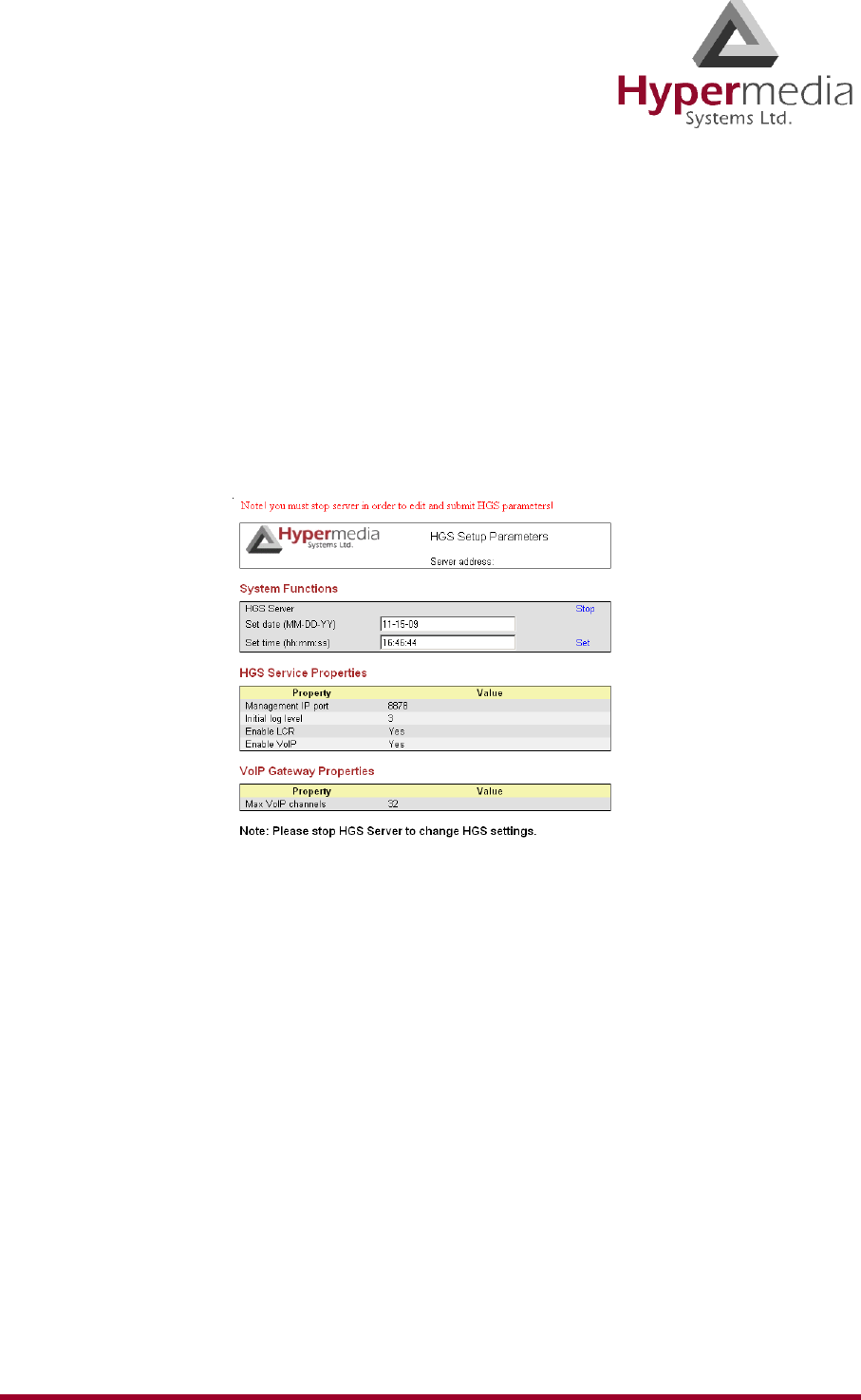
HMC Product Manual 168
Release 3.4: May 2010 HGS Setup Parameters Tool
HGS Setup Parameters Tool
Use the HGS Setup Parameters tool to configure parameters affecting global Hypermedia
Gateway behavior.
To use the HGS Setup Parameters tool:
1. Click the Windows Start button > All Programs.
2. From the Hypermedia program group, select HGS Setup Parameters. The HGS Setup
Parameters logon screen is displayed.
3. Enter your password and click Submit. The HGS Setup Parameters screen is displayed.
Figure 159: HGS Setup Parameters Screen
4. From the HGS Server system function line, click Stop. A confirmation message indicates
that the service was stopped successfully.
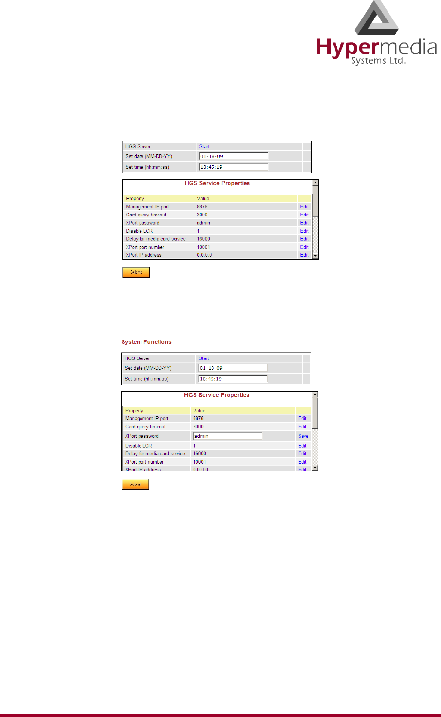
HMC Product Manual 169
Release 3.4: May 2010 HGS Setup Parameters Tool
5. Refresh the browser page, reenter your password and click Submit. The HGS Setup
Parameters screen is displayed in Edit mode.
Figure 160: HGS Setup Parameters Screen in Edit Mode
6. On a parameter line, click Edit. The Value field becomes editable.
Figure 161: Editable Value Field
7. Enter the new value.
8. Click Save.
9. Click Submit.
10. From the HGS Server system function line, click Start. A confirmation message indi-
cates that the service was started successfully.
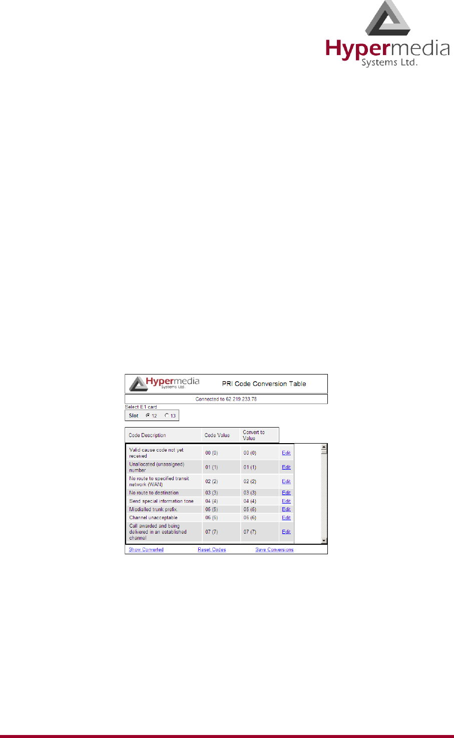
HMC Product Manual 170
Release 3.4: May 2010 PRI Cause Conversion
PRI Cause Conversion
Cause codes represent the reason for releasing the a call. The Hypermedia Gateway can manip-
ulate the releasing Cause code—that is, Convert to Value—if we do not want to report the
exact reason for call release.
To run the PRI Cause Conversion tool:
1. Click the Windows Start button > All Programs.
2. From the Hypermedia program group, select PRI Cause Conversion. The PRI Cause
Conversion logon screen opens in the default browser.
3. Click the warning bar at the top of the screen and, from the dropdown menu, click Allow
Blocked Content. Confirm your choice by clicking Ye s at the confirmation message.
Note: To avoid recurring displays of the warning bar, from the menu bar click Tools >
Internet Options > Advanced > Allow active content to run in files on My Computer.
4. Enter your password and click Submit. The PRI Cause Conversion screen is displayed.
Figure 162: PRI Cause Conversion Screen

HMC Product Manual 171
Release 3.4: May 2010 PRI Cause Conversion
5. On a code description line, click Edit. A dropdown menu is displayed in the Convert to
Value field.
Figure 163: Editable Value Field
6. Select a new value.
7. Click Save.
8. Click Submit.
9. Two additional options exist:
Show Converted
Displays the converted values.
Reset Codes
Assigns the original cause code values.
10. Click Save Conversions.
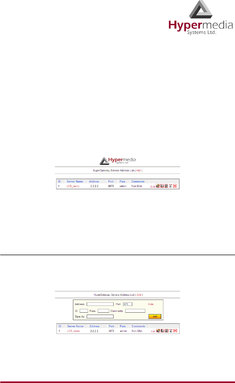
HMC Product Manual 172
Release 3.4: May 2010 Hypermedia Gateway Server List
Hypermedia Gateway Server List
Use the Hypermedia Gateway Server list to review a list of existing servers and to add a new
server. Other Hypermedia configuration and management tools can be accessed from the
Hypermedia Gateway Server list. When accessed from here, the IP address and the password
from the list are used, avoiding the need to re-enter these.
To run the Hypermedia Gateway Server List tool:
1. Click the Windows Start button > All Programs.
2. From the Hypermedia program group, select Server List. The HyperGateway Servers
Address List screen opens in the default browser.
3. Click the warning bar at the top of the screen and, from the dropdown menu, click Allow
Blocked Content. Confirm your choice by clicking Ye s at the confirmation message.
Figure 164: Hypermedia Gateway Server List
Note: To avoid recurring displays of the warning bar, from the menu bar click Tools >
Internet Options > Advanced > Allow active content to run in files on My Computer.
Adding a New Server
To add a new server:
1. Ensure that you know the IP address of the new server.
2. From the top of the screen, click Add. An additional dialog box is displayed.
Figure 165: Add a New Server Screen
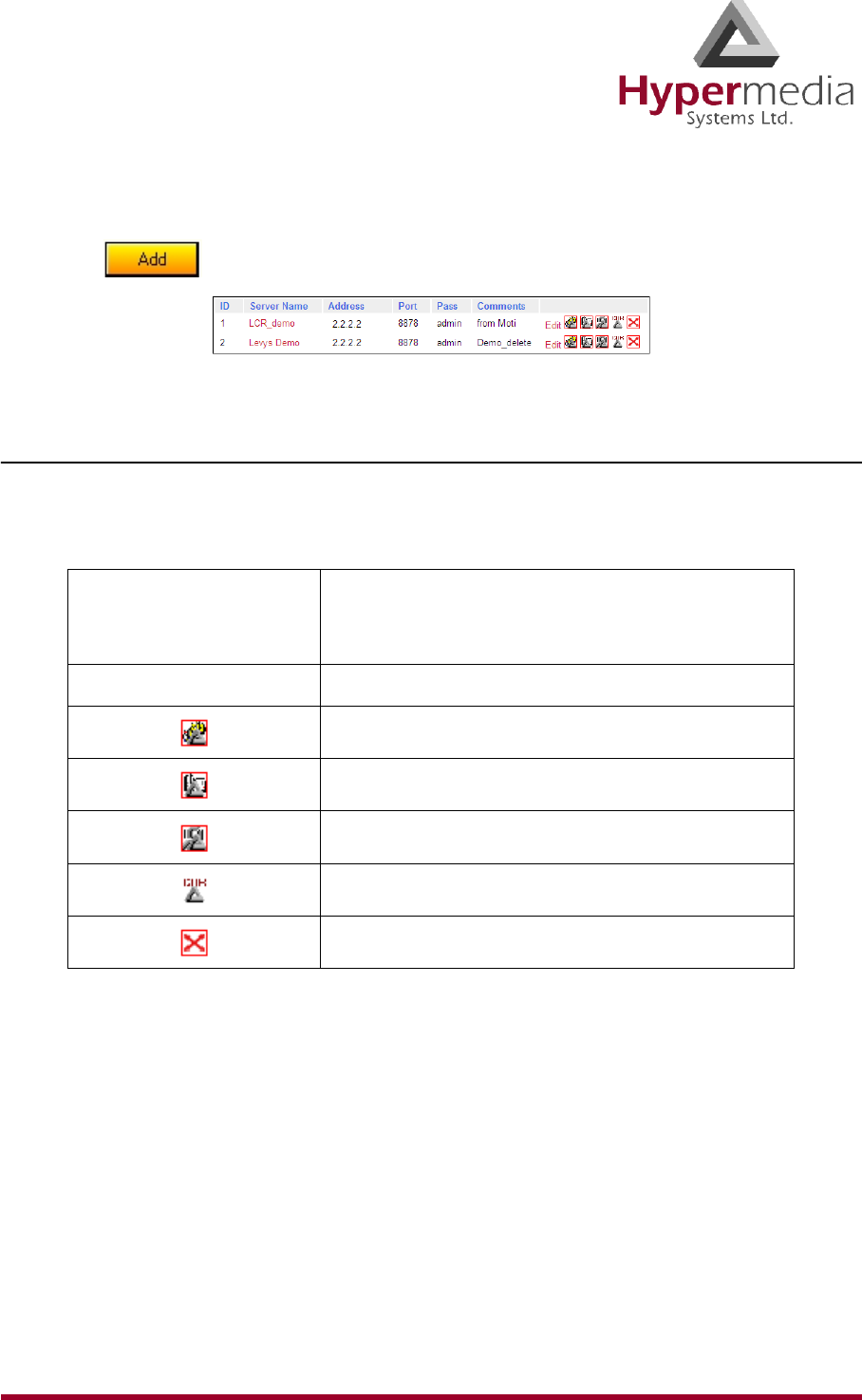
HMC Product Manual 173
Release 3.4: May 2010 Hypermedia Gateway Server List
3. Enter the server parameters.
4. Click . The new server is added to the list.
Figure 166: New Server Appears in List
Accessing Other Tools via the Server List
Use the Gateway Server List to open:
Table 10: Tools Available from the Server List
Clicking the name that
appears in the Server
Name column
Opens the Hypermedia Management Console
Clicking Edit Opens the Server Information window
Opens the HGS Setup Parameters tool
Launches the Log Console
Launches the Service Console
Launches the CDR Console
Deletes the entry

HMC Product Manual 174
Release 3.4: May 2010 Troubleshooting
Troubleshooting
Table 11: Power
Display Problem Solution
System does not start
up No power to the unit Connect power cables
Alarm sounds every
time the system
boots up
When a dual power
supply is used, one
power unit is not
functioning or only
one power unit is
present
Replace faulty power unit.
Add a power unit
Table 12: PRI
Display Problem Solution
Sync. LED (Green)
is blinking
No synchronization
of PRI card
• Check connections to the
PRI card at the PBX or line.
• Verify that the PRI cable is
connected.
• Verify that all pins in the
PRI connector are con-
nected in accordance to the
PRI specifications.
(PRI 1.1 only)
Ready LED (Yel-
low) does not light
Error LED (Red) is
blinking
Card is either not
inserted correctly, or
faulty
Card is faulty
Reinsert the card and restart the
system. If problem continues
replace the card.
Noise on the line
while call in prog-
ress
Synchronization of
PRI card is not set
correctly.
Verify PRI settings for synchro-
nization. Typically the PRI Sync.
settings at the HyperGateway
should be “Slave”.

HMC Product Manual 175
Release 3.4: May 2010 Troubleshooting
Table 13: Cellular
Display Problem Solution
No sync. with net-
work (Green LED is
off)
Antenna is not
located properly
Position the antenna in a place
with better reception.
No sync. with net-
work (Green LED
blinks)
No SIM card Put a working SIM card in the
appropriate channel
Error LED (Red) is
blinking
Ready LED (Yel-
low) does not light
Card is either not
inserted correctly, or
faulty
Reinsert the card and restart the
system. If problem continues
replace the card.
Table 14: MG Card
Display Problem Solution
• LINK LED
(Green) does
not light
• Error LED
(Red) is blink-
ing (50% duty
cycle, not twin-
kling)
• Ready LED
(Yellow) does
not light
No LAN Connection
Card is faulty
Card is either not
inserted correctly, or
faulty
Check connections to the Router.
Reinsert the card and restart the
system. If problem continues
replace the card.

HMC Product Manual 176
Release 3.4: May 2010 Troubleshooting
This page is intentionally blank.

HMC Product Manual 177
Release 3.4: May 2010
Chapter 9
INDEX
Numerics
1st group .................................................. 72
2nd / 3rd group ........................................ 72
A
ACD ......................................105, 115, 116
ACR ................................................... 73, 78
add left ..................................................... 75
adding a new server ............................... 172
advanced call routing .............................. 73
allow blocked content warning ............... 20
allow duplicate CLIs ............................... 27
answer maximum wait ............................ 50
ASR ....................................... 105, 115, 116
authentication
callback ...................................... 27, 146
callthrough ................................. 27, 153
authentication for callback .................... 138
B
balancing SIMs ........................................ 53
BCCH ...................................................... 51
BER ................................................... 55, 56
bi-directional LCR resource ....................71
billing .......................................................67
blocking ...................................................82
calling line identification ...................49
DDI ..................................................112
SIM card ............................................47
voip channels ...................................133
voip lines ..........................................116
C
call routing .............................................111
callback
activation/delegation delay ................28
authentication policy ..................27, 146
automatic DTMF digit duration .........28
automatic DTMF send delay .............28
automatic inter-digit duration ............28
borrowing resources from callthrough 28
cellular ...............................................34
cellular resources ...............................34
dial timeout ........................................28
extended authentication ...................138
line trigger ................................123, 148
log ............................................161, 163

HMC Product Manual 178
Release 3.4: May 2010
remote delegation ............................ 137
user access ............................... 123, 147
web trigger ............................... 123, 147
callback triggers
cellular callback trigger ..................... 35
cellular SMS trigger .......................... 35
LCR ................................................... 88
overview .................................. 140, 149
calling line identification
blocking ............................................. 49
callthrough
authentication policy ................. 27, 153
cellular ............................................... 37
LCR ................................................... 83
log .................................................... 160
overview .......................................... 149
using resources for callback .............. 28
voip .................................................. 103
camp ........................................................ 51
cause codes
PRI conversion ................................ 170
voip .................................................. 113
CDR
callback ............................................ 154
callthrough ....................................... 154
console ............................................. 156
downloading ...................................... 91
LCR ................................................... 96
LCR records ...................................... 90
voip .................................................. 117
clear voip call ........................................ 116
CLI
allow duplicate .................................. 27
blocking ............................................. 49
callback trigger ........................ 123, 148
code ............................................... 122, 147
codecs .................................................... 106
consoles
CDR ................................................. 156
log .................................................... 157
service .............................................. 167
counters ............................................. 46, 48
reset SIM ......................................... 130
cyclic ................................................66, 105
D
dBm .........................................................51
DDI
blocking ...........................................112
filters ................................................108
delay
PIN code inter-digit .........................106
PIN code send ..................................106
delay after DTMF code sent ....................28
delegation for callback ...........................137
delete
saved configuration ............................26
dial filters
cellular ...............................................39
dialtone length .........................................28
downloading
CDR file .............................................91
DTMF
delay ...................................................28
digit duration ......................................28
send delay ..........................................28
DTMF on connect ..........................123, 148
E
early media ............................................105
echo canceller ..........................................31
enable codecs .........................................106
F
filters
add left ...............................................75
cellular ...............................................39
DDI ..................................................108
IP ......................................................107
LCR .............................................75, 85
match condition .................................75
number ...............................................85
number filters ...................................125
trim left ..............................................75
voip dial ...........................................110

HMC Product Manual 179
Release 3.4: May 2010
frame 1
start time ............................................ 76
fully allocated ........................................ 101
G
groups
default ................................................ 67
LCR ................................................... 66
LCR rules .......................................... 72
LCR selection .................................... 70
voip linking .....................................104
VPN ................................................. 124
H
hangup
closes session ..................................... 27
voip call ........................................... 116
HMC
installation ......................................... 18
startup ................................................ 20
I
in filter ............................................... 66, 75
inter-digit duration ................................... 28
internal routing ........................................ 67
IP precedence ........................................ 105
L
LCR log ................................................. 164
line callback trigger ....................... 123, 148
line ID ............................................ 123, 148
linking
cellular channels ................................ 32
LCR ............................................. 61, 63
voip channels ................................... 100
lock period ............................................. 132
locks ........................................................ 44
log
callback .................................... 161, 163
callthrough ....................................... 160
GSM to VoIP ................................... 159
LCR .................................................164
VoIP to GSM ...................................158
log console .............................................157
M
match condition .......................................75
maximum length of call ...........................50
media card fallback ..................................27
media connections
cellular ...............................................32
LCR .............................................61, 63
voip ..................................................100
mobile number ...............................122, 147
multiple subscriber number .....................41
N
number filters ...................................85, 125
number lists and ACR ..............................78
number of calls for ASR/ACD statistics 105
number send delay ...................................28
O
operator ..............................................55, 56
operator locks ..........................................44
out filter .............................................66, 75
outbound only LCR resource ...................71
P
payloads per packet ...............................106
PC1 cards .................................................94
phone2net dial plan ................................111
PIN code ..................................................40
inter-digit delay ................................106
send delay ........................................106
public IP .................................................105
R
reception ..................................................56
remote hangup closes session ..................27
remote party answer timeout ...................28
repeat period ..........128, 130, 131, 133, 135

HMC Product Manual 180
Release 3.4: May 2010
repetitions ................................................ 48
reset
ACD count ....................................... 116
ASR count ....................................... 116
cellular card ....................................... 42
SIM counter ..................................... 130
resources
assigning LCR ................................... 69
LCR ............................................. 61, 63
LCR map ........................................... 68
restore saved configuration ..................... 26
RFC2833 payload .................................. 106
round call length up ................................. 50
rules
ACR ................................................... 80
creating default .................................. 74
LCR callthrough filters ...................... 85
LCR groups ....................................... 72
on destination .................................... 81
on source ........................................... 81
RX BER ............................................. 55, 56
RX level ............................................. 55, 56
S
save
exising configuration ......................... 26
new configuration .............................. 26
select SIM ................................................ 45
serial numbers ......................................... 43
server
adding .............................................. 172
list .................................................... 172
settings ............................................... 21
service console ...................................... 167
set 1st leg
LCR 84
cellular ......................................... 34, 38
voip .................................................. 104
setup parameters .................................... 168
SIM
automatic management ...................... 47
balance ............................................... 53
counters ........................................46, 48
locks ...................................................44
minutes until blocked .........................47
minutes until switched .......................47
multi set ...........................................132
reset counters ...................................130
schedule switch per slot ...................127
schedule switch per system ..............129
select ..................................................45
SIP proxy ...............................................106
SMS
callback log ......................................163
SMS trigger ..............................................35
start times of frames ................................76
steps .........................................................48
store settings on cards ..............................26
switch period ..........................................132
T
tag,number heading .................................78
time frames ..................................72, 73, 76
time periods .............................................48
timeout
answering outgoing call .....................50
callback dial .......................................28
length of call ......................................50
remote party answer ...........................28
triggers
callback ....................................140, 149
cellular callback .................................35
LCR callback .....................................88
line callback .............................123, 148
SMS ...................................................35
web callback ............................123, 147
trim left ....................................................75
type of service ........................................105
U
unstructured supplementary service data .53
user
add ...................................................122
callback access .........................123, 147

HMC Product Manual 181
Release 3.4: May 2010
code ......................................... 122, 147
ID ............................................. 122, 147
mobile number ......................... 122, 147
user input indication .............................. 106
USSD ....................................................... 53
V
voip to line cyclic channel allocation .... 105
volume settings ........................................ 31
VPN ....................................... 123, 124, 147
W
waiting for answer timeout ...................... 50
web callback trigger ...................... 123, 147
white lists ............................................... 107

HMC Product Manual 182
Release 3.4: May 2010