Hytera Mobilfunk TIB500400 TETRA Indoor Base Transceiver User Manual I
Hytera Mobilfunk GmbH TETRA Indoor Base Transceiver I
Contents
- 1. User Manual I
- 2. User Manual II
User Manual I

90DIB500R41IM_FCC02 – 99.1
Secure Communications
Installation, Operation and
Service Manual
DIB-500 R4.1
Digital Indoor Base Station
Installation, Operation and
Service Manual
PV 08.01.xx

DIB-500 R4.1
II Installation, Operation and Service Manual 90DIB500R41IM_FCC02 – 99.1
© 2011 Rohde & Schwarz Professional Mobile Radio GmbH
31848 Bad Münder, Germany
Printed in Germany - Subject to change - Data without tolerance limits is not binding.
Encryption components are subject to German export regulations.

Installation, Operation and Service Manual 90DIB500R41IM_FCC02 – 99.1 III
DIB-500 R4.1 Digital Indoor Base Station
Table of contents
1 Notes on the document . . . . . . . . . . . . . . . . . . . . . . . . . . . . . . . . . . .13
1.1 Objectives of the document . . . . . . . . . . . . . . . . . . . . . . . . . . . . . . . . . . . . 13
1.2 Intended audience of the document . . . . . . . . . . . . . . . . . . . . . . . . . . . . . . 13
1.3 Qualification of the personnel . . . . . . . . . . . . . . . . . . . . . . . . . . . . . . . . . . 14
1.4 Validity of the document . . . . . . . . . . . . . . . . . . . . . . . . . . . . . . . . . . . . . . . 14
1.5 Reading and navigation aids in the document . . . . . . . . . . . . . . . . . . . . . 14
1.6 Figures and special notations used . . . . . . . . . . . . . . . . . . . . . . . . . . . . . . 15
1.6.1 Figures used . . . . . . . . . . . . . . . . . . . . . . . . . . . . . . . . . . . . . . . . . . . . . . . . . 15
1.6.2 Special notations . . . . . . . . . . . . . . . . . . . . . . . . . . . . . . . . . . . . . . . . . . . . . . 15
1.6.2.1 Designations of TIB transceiver module and equipment racks . . . . . . . . . . . 15
1.6.2.2 Sequence of actions . . . . . . . . . . . . . . . . . . . . . . . . . . . . . . . . . . . . . . . . . . . . 16
1.6.2.3 Safety instructions used . . . . . . . . . . . . . . . . . . . . . . . . . . . . . . . . . . . . . . . . . 16
1.6.2.4 General instructions used . . . . . . . . . . . . . . . . . . . . . . . . . . . . . . . . . . . . . . . 17
1.6.2.5 Text formatting used . . . . . . . . . . . . . . . . . . . . . . . . . . . . . . . . . . . . . . . . . . . 17
1.7 Further applicable documents . . . . . . . . . . . . . . . . . . . . . . . . . . . . . . . . . . 18
1.8 Support information . . . . . . . . . . . . . . . . . . . . . . . . . . . . . . . . . . . . . . . . . . . 19
2 Safety regulations . . . . . . . . . . . . . . . . . . . . . . . . . . . . . . . . . . . . . . .21
2.1 Safety instructions and declaration of conformity . . . . . . . . . . . . . . . . . . 21
2.1.1 Safety instructions and declaration of conformity for Europe . . . . . . . . . . . . . 21
2.1.2 Safety instructions and declaration of conformity for North America . . . . . . . 23
2.2 Intended use . . . . . . . . . . . . . . . . . . . . . . . . . . . . . . . . . . . . . . . . . . . . . . . . . 23
2.3 Safety measures . . . . . . . . . . . . . . . . . . . . . . . . . . . . . . . . . . . . . . . . . . . . . . 24
2.3.1 Authorised personnel . . . . . . . . . . . . . . . . . . . . . . . . . . . . . . . . . . . . . . . . . . . 24
2.3.2 Electromagnetic compatibility . . . . . . . . . . . . . . . . . . . . . . . . . . . . . . . . . . . . . 25
2.3.2.1 Electromagnetic compatibility for Europe . . . . . . . . . . . . . . . . . . . . . . . . . . . . 25

DIB-500 R4.1
IV Installation, Operation and Service Manual 90DIB500R41IM_FCC02 – 99.1
2.3.2.2 Electromagnetic compatibility for North America . . . . . . . . . . . . . . . . . . . . . . 25
2.3.3 Notes on the electrical system . . . . . . . . . . . . . . . . . . . . . . . . . . . . . . . . . . . . 26
2.3.4 Hazardous substances . . . . . . . . . . . . . . . . . . . . . . . . . . . . . . . . . . . . . . . . . . 26
2.3.4.1 Hazardous substances in Europe . . . . . . . . . . . . . . . . . . . . . . . . . . . . . . . . . 26
2.3.4.2 Hazardous substances outside Europe . . . . . . . . . . . . . . . . . . . . . . . . . . . . . 26
2.3.5 Product disposal . . . . . . . . . . . . . . . . . . . . . . . . . . . . . . . . . . . . . . . . . . . . . . . 26
2.3.5.1 Product disposal in Europe . . . . . . . . . . . . . . . . . . . . . . . . . . . . . . . . . . . . . . 26
2.3.5.2 Product disposal outside Europe . . . . . . . . . . . . . . . . . . . . . . . . . . . . . . . . . . 27
2.4 Safety Markings . . . . . . . . . . . . . . . . . . . . . . . . . . . . . . . . . . . . . . . . . . . . . . 27
2.4.1 Safety markings on transport boxes . . . . . . . . . . . . . . . . . . . . . . . . . . . . . . . . 27
2.4.2 Safety markings on the product . . . . . . . . . . . . . . . . . . . . . . . . . . . . . . . . . . . 29
3 Product description . . . . . . . . . . . . . . . . . . . . . . . . . . . . . . . . . . . . . .31
3.1 Constituents . . . . . . . . . . . . . . . . . . . . . . . . . . . . . . . . . . . . . . . . . . . . . . . . . 34
3.1.1 Voltage supply and alarming system . . . . . . . . . . . . . . . . . . . . . . . . . . . . . . . 34
3.1.1.1 Terminal block . . . . . . . . . . . . . . . . . . . . . . . . . . . . . . . . . . . . . . . . . . . . . . . . 35
3.1.1.2 Expansion for VAC voltage supply (VAC voltage supply unit) . . . . . . . . . . . . 36
3.1.1.3 Alarm system expansion . . . . . . . . . . . . . . . . . . . . . . . . . . . . . . . . . . . . . . . . 37
3.1.1.4 SC200 – optional (VAC or alarm system expansion) . . . . . . . . . . . . . . . . . . . 38
3.1.1.5 Alarm input/output module – optional (VAC or alarm system expansion) . . . 40
3.1.1.6 Rectifier module – optional (VAC expansion) . . . . . . . . . . . . . . . . . . . . . . . . 40
3.1.2 E1 connection board . . . . . . . . . . . . . . . . . . . . . . . . . . . . . . . . . . . . . . . . . . . 41
3.1.3 Redundancy package with LAN Routing Unit (LRU) . . . . . . . . . . . . . . . . . . . 42
3.1.4 On/off switch . . . . . . . . . . . . . . . . . . . . . . . . . . . . . . . . . . . . . . . . . . . . . . . . . 43
3.1.5 TIB transceiver module (TETRA Indoor Base) . . . . . . . . . . . . . . . . . . . . . . . . 45
3.1.5.1 Overview of possible functions and corresponding software components
on the TIB transceiver module . . . . . . . . . . . . . . . . . . . . . . . . . . . . . . . . . . . . 47

Installation, Operation and Service Manual 90DIB500R41IM_FCC02 – 99.1 V
DIB-500 R4.1
3.1.5.2 Overview of possible functions . . . . . . . . . . . . . . . . . . . . . . . . . . . . . . . . . . . . 49
Base Station Function (BSF) . . . . . . . . . . . . . . . . . . . . . . . . . . . . . . . . . . . . . 49
Switching Controller Function (SCF) . . . . . . . . . . . . . . . . . . . . . . . . . . . . . . . 49
TETRA Vocoder Function (TVF) . . . . . . . . . . . . . . . . . . . . . . . . . . . . . . . . . . 49
Application Gateway (AGW) . . . . . . . . . . . . . . . . . . . . . . . . . . . . . . . . . . . . . 50
Packet Data Gateway (PGW) . . . . . . . . . . . . . . . . . . . . . . . . . . . . . . . . . . . . 50
Telephony Gateway (TGW) . . . . . . . . . . . . . . . . . . . . . . . . . . . . . . . . . . . . . . 50
3.1.5.3 Multi Processor Server Unit (MSU) . . . . . . . . . . . . . . . . . . . . . . . . . . . . . . . . 50
PowerPC . . . . . . . . . . . . . . . . . . . . . . . . . . . . . . . . . . . . . . . . . . . . . . . . . . . . 50
Processing Unit Controller (PUC) . . . . . . . . . . . . . . . . . . . . . . . . . . . . . . . . . 51
GPS module . . . . . . . . . . . . . . . . . . . . . . . . . . . . . . . . . . . . . . . . . . . . . . . . . . 51
3.1.5.4 IntelPC . . . . . . . . . . . . . . . . . . . . . . . . . . . . . . . . . . . . . . . . . . . . . . . . . . . . . . 51
Core Operation Server (COS) . . . . . . . . . . . . . . . . . . . . . . . . . . . . . . . . . . . . 51
TETRA Operation Server (TOS) . . . . . . . . . . . . . . . . . . . . . . . . . . . . . . . . . . 51
IP Switch (IPS) . . . . . . . . . . . . . . . . . . . . . . . . . . . . . . . . . . . . . . . . . . . . . . . . 52
Network Element Manager (NEM-523) . . . . . . . . . . . . . . . . . . . . . . . . . . . . . 52
Packet Data Server (PDS) . . . . . . . . . . . . . . . . . . . . . . . . . . . . . . . . . . . . . . . 52
TETRA Application Platform (TAP) . . . . . . . . . . . . . . . . . . . . . . . . . . . . . . . . 53
SIP Media Gateway (SMG) . . . . . . . . . . . . . . . . . . . . . . . . . . . . . . . . . . . . . . 53
Hardware Guard (HWG) . . . . . . . . . . . . . . . . . . . . . . . . . . . . . . . . . . . . . . . . 53
3.1.5.5 Synthesiser . . . . . . . . . . . . . . . . . . . . . . . . . . . . . . . . . . . . . . . . . . . . . . . . . . 53
3.1.5.6 Power supply . . . . . . . . . . . . . . . . . . . . . . . . . . . . . . . . . . . . . . . . . . . . . . . . . 54
3.1.5.7 Receiver/transmitter unit (transceiver) . . . . . . . . . . . . . . . . . . . . . . . . . . . . . . 54
3.1.6 Antenna Coupling System (ACS) . . . . . . . . . . . . . . . . . . . . . . . . . . . . . . . . . . 54
3.1.7 Fan unit . . . . . . . . . . . . . . . . . . . . . . . . . . . . . . . . . . . . . . . . . . . . . . . . . . . . . 57
3.1.8 Cavity coupler (only for the Cavity variant) . . . . . . . . . . . . . . . . . . . . . . . . . . 58

DIB-500 R4.1
VI Installation, Operation and Service Manual 90DIB500R41IM_FCC02 – 99.1
3.1.9 Redundancy options for the DIB-500 R4.1 or the Base Station Function
(BSF) . . . . . . . . . . . . . . . . . . . . . . . . . . . . . . . . . . . . . . . . . . . . . . . . . . . . . . . 60
3.1.9.1 Redundant Main Control Channel (MCCH) . . . . . . . . . . . . . . . . . . . . . . . . . . 60
3.1.9.2 Transceiver redundancy . . . . . . . . . . . . . . . . . . . . . . . . . . . . . . . . . . . . . . . . . 61
3.1.9.3 Controller redundancy . . . . . . . . . . . . . . . . . . . . . . . . . . . . . . . . . . . . . . . . . . 61
3.1.9.4 Gradual reduction of the carrier capacity . . . . . . . . . . . . . . . . . . . . . . . . . . . . 61
3.1.9.5 Fallback operation . . . . . . . . . . . . . . . . . . . . . . . . . . . . . . . . . . . . . . . . . . . . . 62
3.1.9.6 Stand-alone operation . . . . . . . . . . . . . . . . . . . . . . . . . . . . . . . . . . . . . . . . . . 62
3.1.9.7 Redundancy by means of overlapping radio coverage . . . . . . . . . . . . . . . . . 63
3.2 Interfaces . . . . . . . . . . . . . . . . . . . . . . . . . . . . . . . . . . . . . . . . . . . . . . . . . . . 63
3.3 Wiring diagrams . . . . . . . . . . . . . . . . . . . . . . . . . . . . . . . . . . . . . . . . . . . . . . 64
3.3.1 Internal wiring of the hybrid variant . . . . . . . . . . . . . . . . . . . . . . . . . . . . . . . . 65
3.3.1.1 Internal wiring of the hybrid variant – two carriers . . . . . . . . . . . . . . . . . . . . . 66
3.3.1.2 Internal wiring of the hybrid variant – four carriers . . . . . . . . . . . . . . . . . . . . . 67
3.3.1.3 Hybrid variant – eight carriers . . . . . . . . . . . . . . . . . . . . . . . . . . . . . . . . . . . . 68
3.3.1.4 Hybrid variant – Eight carriers with LRU (redundancy package) . . . . . . . . . . 70
3.3.2 Internal wiring of the cavity variant . . . . . . . . . . . . . . . . . . . . . . . . . . . . . . . . . 72
3.3.2.1 Internal wiring of the cavity variant – two carriers . . . . . . . . . . . . . . . . . . . . . 73
3.3.2.2 Internal wiring of the cavity variant – four carriers . . . . . . . . . . . . . . . . . . . . . 74
3.3.2.3 Internal wiring of the cavity variant – eight carriers . . . . . . . . . . . . . . . . . . . . 75
3.3.2.4 Wiring of cavity equipment rack . . . . . . . . . . . . . . . . . . . . . . . . . . . . . . . . . . . 76
3.3.3 Internal wiring of the high power variant . . . . . . . . . . . . . . . . . . . . . . . . . . . . 77
3.3.3.1 Internal wiring of the high power variant – one carrier . . . . . . . . . . . . . . . . . . 78
3.3.3.2 Internal wiring of high power variant – two carriers . . . . . . . . . . . . . . . . . . . . 79
3.3.4 Internal wiring for FlexibleTx variant . . . . . . . . . . . . . . . . . . . . . . . . . . . . . . . 80
3.3.4.1 Internal wiring of FlexibleTx variant – two carriers . . . . . . . . . . . . . . . . . . . . . 81
3.3.4.2 Internal wiring for FlexibleTx variant – Four carriers . . . . . . . . . . . . . . . . . . . 82

Installation, Operation and Service Manual 90DIB500R41IM_FCC02 – 99.1 VII
DIB-500 R4.1
3.4 Scope of delivery . . . . . . . . . . . . . . . . . . . . . . . . . . . . . . . . . . . . . . . . . . . . . 83
4 Transport and storage . . . . . . . . . . . . . . . . . . . . . . . . . . . . . . . . . . . .85
4.1 Safety measures and prerequisites . . . . . . . . . . . . . . . . . . . . . . . . . . . . . . 85
4.2 Tools, aids and materials . . . . . . . . . . . . . . . . . . . . . . . . . . . . . . . . . . . . . . 86
4.3 Transporting the equipment rack . . . . . . . . . . . . . . . . . . . . . . . . . . . . . . . . 86
4.4 Storage . . . . . . . . . . . . . . . . . . . . . . . . . . . . . . . . . . . . . . . . . . . . . . . . . . . . . 88
5 Setup and commissioning . . . . . . . . . . . . . . . . . . . . . . . . . . . . . . . . .89
5.1 Safety measures and prerequisites . . . . . . . . . . . . . . . . . . . . . . . . . . . . . . 90
5.2 Tools, aids and materials . . . . . . . . . . . . . . . . . . . . . . . . . . . . . . . . . . . . . . 90
5.3 Installing equipment racks . . . . . . . . . . . . . . . . . . . . . . . . . . . . . . . . . . . . . 92
5.4 Removing the top cover of the mounting frame . . . . . . . . . . . . . . . . . . . . 94
5.5 Connecting equipment racks (as of 5 carriers) . . . . . . . . . . . . . . . . . . . . . 95
5.5.1 Assembly of the redundancy package – optional . . . . . . . . . . . . . . . . . . . . . . 96
5.5.1.1 Installing the left top hat rail end bracket . . . . . . . . . . . . . . . . . . . . . . . . . . . . 97
5.5.1.2 Establishing the voltage supply of the LRU . . . . . . . . . . . . . . . . . . . . . . . . . . 98
Connecting the voltage supply of the top hat rail power supply unit . . . . . . . 99
Connecting voltage supply cables to the top hat rail power supply unit . . . . 100
5.5.1.3 Inserting the LRU . . . . . . . . . . . . . . . . . . . . . . . . . . . . . . . . . . . . . . . . . . . . . 102
5.5.1.4 Installing the top hat rail power supply unit . . . . . . . . . . . . . . . . . . . . . . . . . 103
5.5.1.5 Installing the right top hat rail end bracket . . . . . . . . . . . . . . . . . . . . . . . . . . 105
5.5.2 Connecting the equipment racks A and B . . . . . . . . . . . . . . . . . . . . . . . . . . 105
5.6 Connection to the electrical system . . . . . . . . . . . . . . . . . . . . . . . . . . . . . 107
5.6.1 Connection with the grounding system . . . . . . . . . . . . . . . . . . . . . . . . . . . . 107
5.6.2 Defining the reference potential . . . . . . . . . . . . . . . . . . . . . . . . . . . . . . . . . . 108
5.6.3 Connecting the voltage supply . . . . . . . . . . . . . . . . . . . . . . . . . . . . . . . . . . . 110
5.6.3.1 Connecting the VDC voltage supply . . . . . . . . . . . . . . . . . . . . . . . . . . . . . . 110

DIB-500 R4.1
VIII Installation, Operation and Service Manual 90DIB500R41IM_FCC02 – 99.1
5.6.3.2 Connecting the VAC voltage supply – optional . . . . . . . . . . . . . . . . . . . . . . 112
5.7 Connecting Ethernet cables . . . . . . . . . . . . . . . . . . . . . . . . . . . . . . . . . . . 113
5.8 Installing the GPS antenna . . . . . . . . . . . . . . . . . . . . . . . . . . . . . . . . . . . . 114
5.9 Installing the GPS protector - optional . . . . . . . . . . . . . . . . . . . . . . . . . . 117
5.10 Connecting antennas . . . . . . . . . . . . . . . . . . . . . . . . . . . . . . . . . . . . . . . . . 119
5.10.1 Connecting antennas (GPS and TETRA) . . . . . . . . . . . . . . . . . . . . . . . . . . 119
5.10.2 Connection of external antenna coupling systems – Optionally, only
FlexibleTx variant . . . . . . . . . . . . . . . . . . . . . . . . . . . . . . . . . . . . . . . . . . . . 121
5.11 Connecting external alarm sensors (LSA+) . . . . . . . . . . . . . . . . . . . . . . . 123
5.12 Connecting external alarms – optional, with VAC or alerting
expansion . . . . . . . . . . . . . . . . . . . . . . . . . . . . . . . . . . . . . . . . . . . . . . . . . . 123
5.12.1 Removing the top cover of the equipment rack . . . . . . . . . . . . . . . . . . . . . . 124
5.12.2 Connecting external alarms . . . . . . . . . . . . . . . . . . . . . . . . . . . . . . . . . . . . . 126
5.12.3 Mounting the top cover of the mounting frame . . . . . . . . . . . . . . . . . . . . . . . 128
5.13 Mounting the top cover of the equipment rack . . . . . . . . . . . . . . . . . . . . 129
5.14 Switching on the voltage source . . . . . . . . . . . . . . . . . . . . . . . . . . . . . . . 129
5.15 Switching on the DIB-500 R4.1 . . . . . . . . . . . . . . . . . . . . . . . . . . . . . . . . . 129
6 Configuration . . . . . . . . . . . . . . . . . . . . . . . . . . . . . . . . . . . . . . . . . .131
6.1 Configuring the software . . . . . . . . . . . . . . . . . . . . . . . . . . . . . . . . . . . . . . 131
6.1.1 Work equipment . . . . . . . . . . . . . . . . . . . . . . . . . . . . . . . . . . . . . . . . . . . . . . 132
6.1.2 Preparatory measures . . . . . . . . . . . . . . . . . . . . . . . . . . . . . . . . . . . . . . . . . 132
6.1.2.1 Connecting the service computer to the TIB transceiver module . . . . . . . . . 133
6.1.3 Deleting the ARP buffer . . . . . . . . . . . . . . . . . . . . . . . . . . . . . . . . . . . . . . . . 134
6.1.4 Configuring and generating network configurations via the NMC-515
ConfigurationManager . . . . . . . . . . . . . . . . . . . . . . . . . . . . . . . . . . . . . . . . . 134
6.1.5 Creating the download repository . . . . . . . . . . . . . . . . . . . . . . . . . . . . . . . . 135

Installation, Operation and Service Manual 90DIB500R41IM_FCC02 – 99.1 IX
DIB-500 R4.1
6.1.6 Adapting IP addresses (with more than one transceiver module) . . . . . . . . 135
6.1.6.1 Adapting the IP addresses (IntelPC) . . . . . . . . . . . . . . . . . . . . . . . . . . . . . . 135
6.1.6.2 Adapting the IP addresses (PowerPC) . . . . . . . . . . . . . . . . . . . . . . . . . . . . 138
6.1.7 Performing an initial download via NMC-522 DownloadManager . . . . . . . . 142
6.2 Adjusting a cavity coupler – optional (cavity variant only) . . . . . . . . . . 143
6.2.1 Tools and aids . . . . . . . . . . . . . . . . . . . . . . . . . . . . . . . . . . . . . . . . . . . . . . . 144
6.2.2 Setting the output rating . . . . . . . . . . . . . . . . . . . . . . . . . . . . . . . . . . . . . . . . 144
6.2.3 Measuring and checking the carriers (impedance adjustment) . . . . . . . . . . 146
6.3 Concluding tasks . . . . . . . . . . . . . . . . . . . . . . . . . . . . . . . . . . . . . . . . . . . . 150
7 Function tests and operating surveillance . . . . . . . . . . . . . . . . . .151
7.1 Work equipment for function tests . . . . . . . . . . . . . . . . . . . . . . . . . . . . . . 152
7.2 Checking operating states . . . . . . . . . . . . . . . . . . . . . . . . . . . . . . . . . . . . 152
7.2.1 Checking operating statuses via the NMC-511 FaultManager . . . . . . . . . . . 153
7.2.2 Checking operating statuses via LEDs of the TIB . . . . . . . . . . . . . . . . . . . . 153
7.2.3 Checking operating statuses via LEDs of the SC200 or rectifier modules –
optional (only for VAC voltage supply) . . . . . . . . . . . . . . . . . . . . . . . . . . . . . 154
7.2.4 Checking operating states via SMT-500 . . . . . . . . . . . . . . . . . . . . . . . . . . . 155
7.3 Checking the reachability of network elements . . . . . . . . . . . . . . . . . . . 155
7.4 Checking voice channels . . . . . . . . . . . . . . . . . . . . . . . . . . . . . . . . . . . . . 156
7.4.1 Checking the voice channel (two carriers) . . . . . . . . . . . . . . . . . . . . . . . . . . 156
7.4.2 Checking the voice channel (more than two carriers) . . . . . . . . . . . . . . . . . 157
7.5 Checking standby carriers – optional . . . . . . . . . . . . . . . . . . . . . . . . . . . 158
7.6 Function tests and operating surveillance GPS . . . . . . . . . . . . . . . . . . . 159
7.6.1 Checking the installation site of the GPS antenna . . . . . . . . . . . . . . . . . . . . 159
7.6.2 GPS operational monitoring (via NMC-511 FaultManager) . . . . . . . . . . . . . 159
7.6.3 Function tests and fault analysis GPS . . . . . . . . . . . . . . . . . . . . . . . . . . . . . 161

DIB-500 R4.1
XInstallation, Operation and Service Manual 90DIB500R41IM_FCC02 – 99.1
7.7 Checking external antenna coupling systems . . . . . . . . . . . . . . . . . . . . 162
8 Service interruption . . . . . . . . . . . . . . . . . . . . . . . . . . . . . . . . . . . .163
8.1 Temporary service interruption . . . . . . . . . . . . . . . . . . . . . . . . . . . . . . . . 163
8.2 Permanent service interruption . . . . . . . . . . . . . . . . . . . . . . . . . . . . . . . . 164
9 Recommissioning . . . . . . . . . . . . . . . . . . . . . . . . . . . . . . . . . . . . . .167
9.1 Recommissioning after a temporary service interruption . . . . . . . . . . . 167
9.2 Recommissioning after a permanent service interruption . . . . . . . . . . 168
10 Maintenance . . . . . . . . . . . . . . . . . . . . . . . . . . . . . . . . . . . . . . . . . . .169
10.1 Maintenance tasks . . . . . . . . . . . . . . . . . . . . . . . . . . . . . . . . . . . . . . . . . . . 169
10.2 Periodical visual inspections . . . . . . . . . . . . . . . . . . . . . . . . . . . . . . . . . . 169
11 Component replacement . . . . . . . . . . . . . . . . . . . . . . . . . . . . . . . . .171
11.1 Safety measures and prerequisites . . . . . . . . . . . . . . . . . . . . . . . . . . . . . 171
11.2 Overview of replacement components and tools, aids and materials . 172
11.2.1 Replacing the TIB transceiver module (tools and aids) . . . . . . . . . . . . . . . . 172
11.2.2 Replacing the ACS (tools and aids) . . . . . . . . . . . . . . . . . . . . . . . . . . . . . . . 173
11.2.3 Replacing components of the fan unit (tools, aids and materials) . . . . . . . . 173
11.2.4 Replacing the LRU (tools and aids) . . . . . . . . . . . . . . . . . . . . . . . . . . . . . . . 173
11.2.5 Replacing the top hat rail power supply unit (tools and aids) . . . . . . . . . . . . 173
11.2.6 Replacing components of the mounting frame/the voltage supply unit
(tools, aids and materials) . . . . . . . . . . . . . . . . . . . . . . . . . . . . . . . . . . . . . . 174
11.2.7 Replacing cavity couplers (tools and aids) . . . . . . . . . . . . . . . . . . . . . . . . . . 174
11.2.8 Replacing the GPS protector (tools and aids) . . . . . . . . . . . . . . . . . . . . . . . 175
11.3 Replacing the TIB . . . . . . . . . . . . . . . . . . . . . . . . . . . . . . . . . . . . . . . . . . . . 175
11.3.1 Removing the TIB . . . . . . . . . . . . . . . . . . . . . . . . . . . . . . . . . . . . . . . . . . . . 177
11.3.2 Installing the TIB . . . . . . . . . . . . . . . . . . . . . . . . . . . . . . . . . . . . . . . . . . . . . 178
11.3.3 Software update and configuration of the TIB . . . . . . . . . . . . . . . . . . . . . . . 179

Installation, Operation and Service Manual 90DIB500R41IM_FCC02 – 99.1 XI
DIB-500 R4.1
11.4 Replacing the ACS . . . . . . . . . . . . . . . . . . . . . . . . . . . . . . . . . . . . . . . . . . . 179
11.4.1 Removing the ACS . . . . . . . . . . . . . . . . . . . . . . . . . . . . . . . . . . . . . . . . . . . . 181
11.4.2 Installing the ACS . . . . . . . . . . . . . . . . . . . . . . . . . . . . . . . . . . . . . . . . . . . . . 183
11.5 Replacing fan unit constituents . . . . . . . . . . . . . . . . . . . . . . . . . . . . . . . . 184
11.5.1 Replacing the air filter pad . . . . . . . . . . . . . . . . . . . . . . . . . . . . . . . . . . . . . . 184
11.5.1.1 Removing the air filter pad . . . . . . . . . . . . . . . . . . . . . . . . . . . . . . . . . . . . . . 184
11.5.1.2 Installing the air filter pad . . . . . . . . . . . . . . . . . . . . . . . . . . . . . . . . . . . . . . . 185
11.5.2 Replacing the fan subrack . . . . . . . . . . . . . . . . . . . . . . . . . . . . . . . . . . . . . . 187
11.5.2.1 Removing the fan subrack . . . . . . . . . . . . . . . . . . . . . . . . . . . . . . . . . . . . . . 187
11.5.2.2 Installing the fan subrack . . . . . . . . . . . . . . . . . . . . . . . . . . . . . . . . . . . . . . . 188
11.6 Replacing the LRU – optional (redundancy package) . . . . . . . . . . . . . . 188
11.6.1 Removing the LRU . . . . . . . . . . . . . . . . . . . . . . . . . . . . . . . . . . . . . . . . . . . . 189
11.6.2 Inserting the LRU . . . . . . . . . . . . . . . . . . . . . . . . . . . . . . . . . . . . . . . . . . . . . 190
11.7 Replacing the top hat rail – optional (redundancy package) . . . . . . . . . 190
11.7.1 Removing the top hat rail power supply unit . . . . . . . . . . . . . . . . . . . . . . . . 191
11.7.2 Installing the top hat rail power supply unit . . . . . . . . . . . . . . . . . . . . . . . . . 192
11.8 Replacing components of the VAC and alarm system expansion –
optional . . . . . . . . . . . . . . . . . . . . . . . . . . . . . . . . . . . . . . . . . . . . . . . . . . . . 192
11.8.1 Replacing rectifier modules . . . . . . . . . . . . . . . . . . . . . . . . . . . . . . . . . . . . . 193
11.8.1.1 Uninstalling rectifier modules . . . . . . . . . . . . . . . . . . . . . . . . . . . . . . . . . . . . 193
11.8.1.2 Installing rectifier modules . . . . . . . . . . . . . . . . . . . . . . . . . . . . . . . . . . . . . . 195
11.8.2 Replacing the mounting frame and the SC200 . . . . . . . . . . . . . . . . . . . . . . 196
11.8.2.1 Preparatory measures . . . . . . . . . . . . . . . . . . . . . . . . . . . . . . . . . . . . . . . . . 197
Disconnecting external alarms (via alarm input/output module) . . . . . . . . . 198
Removing connections of the SC200 . . . . . . . . . . . . . . . . . . . . . . . . . . . . . . 199
Removing Plugs with Earthing Contact – optional (only for VAC expansion) 200
11.8.2.2 Replacing the mounting frame and the SC200 . . . . . . . . . . . . . . . . . . . . . . 201

DIB-500 R4.1
XII Installation, Operation and Service Manual 90DIB500R41IM_FCC02 – 99.1
Removing the mounting frame . . . . . . . . . . . . . . . . . . . . . . . . . . . . . . . . . . . 201
Preparing the mounting frame . . . . . . . . . . . . . . . . . . . . . . . . . . . . . . . . . . . 203
Installing the mounting frame . . . . . . . . . . . . . . . . . . . . . . . . . . . . . . . . . . . . 204
Attaching connectors of the SC200 . . . . . . . . . . . . . . . . . . . . . . . . . . . . . . . 206
11.8.2.3 Concluding tasks . . . . . . . . . . . . . . . . . . . . . . . . . . . . . . . . . . . . . . . . . . . . . 207
Installing Plugs with Earthing Contact – optional (only for VAC expansion) 207
11.8.2.4 Configuring the SC200 . . . . . . . . . . . . . . . . . . . . . . . . . . . . . . . . . . . . . . . . . 208
Installing the "DCTools" application . . . . . . . . . . . . . . . . . . . . . . . . . . . . . . . 209
Configuring the orientation of the SC200 display window (local) . . . . . . . . . 209
Configuring IP settings of the SC200 (local) . . . . . . . . . . . . . . . . . . . . . . . . 211
Loading the SC200 configuration file (via the "DCTools" application) . . . . . 213
Uninstalling the "DCTools" application . . . . . . . . . . . . . . . . . . . . . . . . . . . . . 218
11.9 Replacing cavity couplers – optional (cavity variants only) . . . . . . . . . 218
11.9.1 Replacing a cavity coupler . . . . . . . . . . . . . . . . . . . . . . . . . . . . . . . . . . . . . . 219
11.9.1.1 Removing a cavity coupler . . . . . . . . . . . . . . . . . . . . . . . . . . . . . . . . . . . . . . 219
11.9.1.2 Installing the new cavity coupler . . . . . . . . . . . . . . . . . . . . . . . . . . . . . . . . . 220
11.10 Replacing the GPS protector – optional . . . . . . . . . . . . . . . . . . . . . . . . . 221
11.10.1 Removing the GPS protector . . . . . . . . . . . . . . . . . . . . . . . . . . . . . . . . . . . . 222
11.10.2 Installing the GPS protector . . . . . . . . . . . . . . . . . . . . . . . . . . . . . . . . . . . . . 222

Installation, Operation and Service Manual 90DIB500R41IM_FCC02 – 99.1 13
DIB-500 R4.1 Notes on the document
Objectives of the document
1 Notes on the document
This chapter provides information on using the document. In addition, it names the
requirements for using the product/system.
1.1 Objectives of the document
The present document from Rohde & Schwarz Professional Mobile Radio GmbH
describes the procedures that are required for the activities on and with the
DIB-500 R4.1 product:
|Transport and storage
|Setup and commissioning
|Configuration
|Function tests
|Service interruption
|Maintenance
|Component replacement
In this context, it describes the relevant safety regulations as well as the components
and operation of the product that is used in the ACCESSNET®-T IP mobile radio sys-
tem.
1.2 Intended audience of the document
The present document is intended for all persons who
|operate an ACCESSNET®-T IP network,
|install the product on site
|connect the electrical system of the product on site
|commission and decommission the product,
|maintain the product,
|replace product components,
|transport and store the product.
Each person commissioned with performing the tasks mentioned above with or on the
system must have read and understood the present document and the associated
accompanying documentation.
DIB-500 R4.1 Notes on the document
Qualification of the personnel
14 Installation, Operation and Service Manual 90DIB500R41IM_FCC02 – 99.1
1.3 Qualification of the personnel
Only specialised personnel is permitted to perform the tasks described in the present
document. The specialised personnel must be trained and authorised to perform these
tasks.
Specialists are persons, who:
|are trained and experienced in the corresponding field.
|are familiar with the applicable standards, regulations and provisions associated
with the corresponding task.
1.4 Validity of the document
The validity of the present document is indicated on the title page by the PV information
(Package Version).
By default, the feature release is always indicated on the title page so that the present
document is also valid for the following maintenance releases. Maintenance releases
are not specified since they do not result in any functional expansions/changes.
Table 1.1 describes the meaning of the PV information.
1.5 Reading and navigation aids in the document
As reading and navigation aids, overview tables have been provided at the beginning of
the respective chapters in the present document, for example Table 5.1 on page 89.
These are to provide the reader with an overview of the tasks to be performed. In addi-
tion, they indicate the order in which the tasks are to be performed. When you have
completed a work step, always navigate to the next work step via the overview table to
ensure that the tasks are performed in the correct order. The overview tables are useful
for readers of the printed document (indication of the corresponding sections) as well as
for readers of a PDF document at the PC (via active cross-references to the corre-
sponding sections).
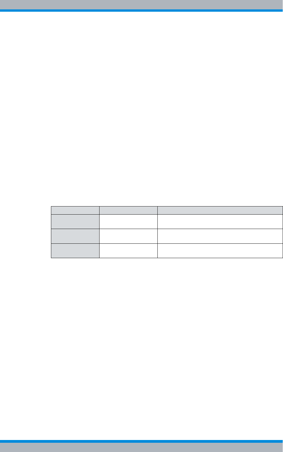
Table 1.1 Meaning of PV information
PV information Description Description
PV xx.yy.zz Main release Identifies the main release. This information
remains unchanged during the life cycle of a PV.
PV xx.yy.zz Feature release Identifies functional expansions/changes within
the main release.
PV xx.yy.zz Maintenance release Identifies maintenance activities within the main
release/feature release.

Installation, Operation and Service Manual 90DIB500R41IM_FCC02 – 99.1 15
DIB-500 R4.1 Notes on the document
Figures and special notations used
1.6 Figures and special notations used
Figures and symbols are used in the present document. They serve for presenting the
product and for emphasizing particular pieces of information.
1.6.1 Figures used
The figures used in this document show the product in a simplified form where neces-
sary for clarity (e. g. technical drawings). They refer to different product designs. If not
described otherwise, the respective figure relates to the standard product design.
1.6.2 Special notations
The special notations described in the following serve for the enhanced comprehensibil-
ity of information. They emphasize specific pieces of information, help you to recognize
this information fast and take corresponding measures.
1.6.2.1 Designations of TIB transceiver module and equipment racks
The base station DIB-500 R4.1 provides a maximum of two TIB transceiver modules
(TETRA Indoor Base Transceiver) which, in turn, can provide up to two carriers. For
variants of the DIB-500 R4.1 with more than four carriers, they are provided in two
equipment racks.
For this reason, the documentation of the DIB-500 R4.1 requires a unique naming of the
equipment racks and the TIB transceiver modules.
Table 1.2 shows the naming scheme used of the equipment racks and the TIB trans-
ceiver modules in this document.
Table 1.2 Naming scheme of the equipment racks and the TIB transceiver modules
Name Description
Equipment rack A the first equipment rack for a DIB-500 R4.1 with more than four carriers
Equipment rack B the second equipment rack for a DIB-500 R4.1 with more than four carri-
ers
TIB A the first TIB transceiver module. For a DIB-500 R4.1 with more than four
carriers in the first equipment rack
TIB B the second TIB transceiver module. For a DIB-500 R4.1 with more than
four carriers in the first equipment rack
TIB C the first TIB transceiver module in the second equipment rack of a
DIB-500 R4.1 with more than four carriers
TIB D the second TIB transceiver module in the second equipment rack of a
DIB-500 R4.1 with more than four carriers
Carrier A the first carrier of a TIB transceiver module
Carrier B the second carrier of a TIB transceiver module
TIB carrier A1the first carrier of the first TIB transceiver module
TIB carrier A2the second carrier of the first TIB transceiver module

DIB-500 R4.1 Notes on the document
Figures and special notations used
16 Installation, Operation and Service Manual 90DIB500R41IM_FCC02 – 99.1
1.6.2.2 Sequence of actions
Standard operation procedures guide you step by step through a sequence of actions
until you have reached the desired goal.
Example of a sequence of actions:
Goal of the actions
Preparation:
✓List of the prerequisite(s) for an action
✓...
Carry out the following steps:
➔Description of an individual work step.
➥A possible result of the work step just performed.
1. Description of the first of multiple work steps.
➥A possible result of the work step just performed.
2. Description of the second work step.
✓Confirmation: Results of the entire sequence of actions.
1.6.2.3 Safety instructions used
Safety instructions in this document point to a hazard that may put persons or the prod-
uct/system at risk.
Safety instructions will point out:
|the nature of the hazard,
|the source of the hazard,
|measures to be taken to avert the specified hazard.
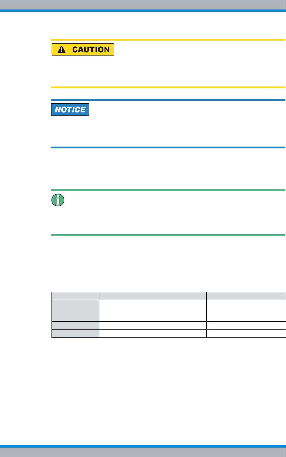
Shown below are four safety advice symbols which indicate the severity of the danger
by means of different keywords (danger, warning, caution, attention). The symbols
shown may vary depending on the nature and source of the danger.
This symbol identifies safety instructions
You are warned of an imminent danger for the life or health of persons.
➔The arrow identifies a precautionary measure designed to avert this danger.
This symbol identifies safety instructions
You are warned of a potential hazard for the life or health of persons.
➔The arrow identifies a precautionary measure designed to avert this danger.
Installation, Operation and Service Manual 90DIB500R41IM_FCC02 – 99.1 17
DIB-500 R4.1 Notes on the document
Figures and special notations used
This symbol identifies safety instructions
You are warned of a potentially hazardous situation for the life or health of persons.
➔The arrow identifies a precautionary measure designed to avert this danger.
This symbol identifies safety instructions
You are alerted of a hazard for the product/system.
➔The arrow identifies a precautionary measure designed to avert this danger.
1.6.2.4 General instructions used
General instructions provide supplementary and useful information.
Important Information
This symbol identifies information that may assist in handling and using the product/sys-
tem. This includes references to further information.
1.6.2.5 Text formatting used
Table 1.3 provides an overview of text formats used and describes the significance of
these formats.
Table 1.3 Text formatting used
Text formatting Description Example
Example Identifies components of the user inter-
face of software components such as net-
work management clients (NMC).
Buttons, dialogues etc.
Example Identifies required inputs. Passwords, IP addresses etc.
Example Identifies outputs. Panel outputs etc.

DIB-500 R4.1 Notes on the document
Further applicable documents
18 Installation, Operation and Service Manual 90DIB500R41IM_FCC02 – 99.1
1.7 Further applicable documents
Apart from the present documentation, the scope of delivery of the product includes
additional documents. In addition to the contents of the present documentation, all the
other documents associated with the product must always be taken into consideration.
They are mandatory for the use of the product.
These are:
|Technical data,
describe the technical properties of the product
|Site Requirements,
describe the requirements for the site where the product is used.
|NMC-511 FaultManager User Manual
contains information required for the proper operation of the product.
|NMC-515 ConfigurationManager User Manual
contains information required for the proper operation of the product.
|NMC-522 DownloadManager User Manual
contains information required for the proper operation of the product.
|"Service Computer for ACCESSNET®-T IP" configuration manual
describes the configuration of the service computer that is used for the installation
and commissioning of network constituents of an ACCESSNET®-T IP as well as for
service and maintenance purposes.
|SMT-500 Operating Manual
describes the commissioning, operation and decommissioning of the product.
|Open Source Acknowledgement
contains information on the respective Open Source software the product com-
prises, including the information on the license(s) used and the related license
agreements.
|GPS Protector Technical Data
describe the technical properties of the GPS Protector.
|project-specific document such as the "Base Design" document, where applicable:
describes the implemented network and the associated properties and require-
ments.
Further applicable documents
Please also heed the documentation of the third-party devices connected to the product
to prevent negative effects or problems with product.

Installation, Operation and Service Manual 90DIB500R41IM_FCC02 – 99.1 19
DIB-500 R4.1 Notes on the document
Support information
1.8 Support information
If you have any questions or suggestions regarding Rohde & Schwarz Professional
Mobile Radio GmbH products, please contact your local service partner responsible or
the Rohde & Schwarz Professional Mobile Radio GmbH Support Team directly.
For a fast and cost-efficient solution of technical problems during the operation of your
ACCESSNET®-T IP network, Rohde & Schwarz Professional Mobile Radio GmbH
offers support contracts upon request. For information on this topic, please also revert
to our responsible service partner or directly to Rohde & Schwarz Professional Mobile
Radio GmbH.
Product training courses assist you in making use of the full scope of features and capa-
bilities of your ACCESSNET®-T IP network. For information on the training program of
Rohde & Schwarz Professional Mobile Radio GmbH, please revert to our responsible
service partner, to Rohde & Schwarz Professional Mobile Radio GmbH or directly to
Rohde & Schwarz.
Rohde & Schwarz Professional Mobile Radio GmbH
Fritz-Hahne-Straße 7
D-31848 Bad Münder
Germany
Telephone:+49 (0)5042/9 98-0
Fax: +49 (0)5042/9 98-105
www.pmr.rohde-schwarz.com

DIB-500 R4.1 Notes on the document
Support information
20 Installation, Operation and Service Manual 90DIB500R41IM_FCC02 – 99.1

Installation, Operation and Service Manual 90DIB500R41IM_FCC02 – 99.1 21
DIB-500 R4.1 Safety regulations
Safety instructions and declaration of conformity
2 Safety regulations
This chapter describes the safety regulations relevant for using the product.
2.1 Safety instructions and declaration of conformity
The operation of the product is subject to the statutory provisions of the respective
country, in which the product is used. For the operation, the required operating licences
must be requested from the responsible local authorities. Particularly the frequency
range used must be reserved for the respective purpose in the country, in which the
product is used. The user of the product is responsible for observing the legal regula-
tions and intended use.
2.1.1 Safety instructions and declaration of conformity for Europe
The product conforms with the general requirements of the responsible European
Directives. This is confirmed by the marking (CE) of the installed components. The Dec-
larations of Conformity of the installed components may be viewed upon request.
The directive on radio equipment and telecommunications terminal equipment (Gesetz
über Funkanlagen und Telekommunikationsendeinrichtungen (FTEG)) implemented by
the European Directive 99/5/EC (R&TTE) is applicable in Germany. The product com-
plies with the fundamental requirements and the other relevant provisions of this direc-
tive.
The product is assigned the equipment class code for radio equipment of class 2 (2.12)
and is marked as follows.
Figure 2.1 Conformity: CE marking
Within the scope of the European Directive 99/5/EC, the network operator must ensure
that the health and safety of the product user and other persons, (Article 3 (1)a of 99/5/
EC and 1999/519/EC) is warranted. With regard to the exposure of persons to electro-
magnetic fields (110 MHz to 40 GHz), product standard EN 50385 must be applied.
Within the EU, the product is intended for use in the following member states: Austria
(AT), Belgium (BE), Bulgaria (BG), Switzerland/Liechtenstein (CH), Cyprus (CY), Czech
Republic (CZ), Germany (DE), Denmark (DK), Estonia (EE), Spain (ES), Finland (FI),
France (FR), Greece (GR), Hungary (HU), Ireland (IE), Iceland (IS), Italy (IT), Lithuania
(LT), Latvia (LV), Netherlands (NL), Norway (NO), Romania (RO), Sweden (SE), Slove-
nia (SI), Slovakia (SK), Turkey (TR), England (UK).
The use of the respective frequency ranges may vary depending on the country of use.
If you have any questions, please contact Rohde & Schwarz Professional Mobile Radio
GmbH.

DIB-500 R4.1 Safety regulations
Safety instructions and declaration of conformity
22 Installation, Operation and Service Manual 90DIB500R41IM_FCC02 – 99.1
The general instructions on safety and accident prevention are documented in the Acci-
dent Prevention Guideline "General Regulations" (BGV A1)1) . For work performed on
electrical installations, the Accident Prevention Regulations (BGV A3) "Electrical Instal-
lations" must be heeded.
The product complies with the safety requirements of the European Low Voltage Direc-
tive (2006/95/EC [73/23/EEC]) due to the application of the standard EN 60950-1. The
requirements of this standard must not be violated when using the product.
The operator is responsible for ensuring that:
|the product is used exclusively within the scope of the intended use.
|work on the electrical installation is performed only by experts that have been
trained accordingly
|special legal requirements that govern the operation of the product are complied
with
|product modifications or expansions:
– are performed only after having consulted Rohde & Schwarz Professional Mobile
Radio GmbH.
– comply with the state of the art
– take into consideration the applicable national and international provisions
– are performed exclusively by trained specialists, who have been authorized
accordingly.
|damage to the product and product defects are immediately remedied by specialists
that have been trained and authorized accordingly.
|appropriate measures are taken against radio interference.
|any defects in the service room that come up later on are eliminated immediately.
|for subsequent modifications of the service room, the requirements described in the
present document are always taken into consideration.
|appropriate fire precautions are taken as required (e.g. the use of appropriate fire
extinguishers).
|special legal requirements that control the operation and handling of batteries and
battery systems, if used, are complied with and that appropriate safety devices and
measures are provided and taken as required.
Country-specific laws and provisions
All the stipulated laws and provisions of the respective country of use shall always
apply. The operator is responsible for the adherence to these laws and provisions.
1) HVBG: Federation of German Industrial Trade Associations, Sankt Augustin, publisher of
the Accident Prevention Guidelines. For sources of supply, please revert to the respon-
sible Accident Prevention and Insurance Association office.

Installation, Operation and Service Manual 90DIB500R41IM_FCC02 – 99.1 23
DIB-500 R4.1 Safety regulations
Intended use
2.1.2 Safety instructions and declaration of conformity for North America
The product complies with the requirements of the Federal Communications Commis-
sion (FCC).
This device complies with part 15 of the FCC Rules. Operation is subject to the follow-
ing two conditions:
|This device may not cause harmful interference, and
|this device must accept any interference received, including interference that may
cause undesired operation.
Changes or modifications not expressly approved by the party responsible for compli-
ance could void the user's authority to operate the equipment.
The product complies with the requirements of Industry Canada (IC).
Le présent appareil est conforme aux CNR d'Industrie Canada applicables aux appar-
eils radio exempts de licence. L'exploitation est autorisée aux deux conditions
suivantes :
|l'appareil ne doit pas produire de brouillage, et
|l'utilisateur de l'appareil doit accepter tout brouillage radioélectrique subi, même si
le brouillage est susceptible d'en compromettre le fonctionnement.
This device complies with Industry Canada licence-exempt RSS standard(s). Operation
is subject to the following two conditions:
|this device may not cause interference, and
|this device must accept any interference, including interference that may cause
undesired operation of the device.
2.2 Intended use
The product is exclusively designed for being used as a professional TETRA communi-
cation system. In this application it is used for the wireless communication between sub-
scribers equipped with the corresponding mobile stations as well as for switching calls
and transferring data between subscribers of TETRA (Terrestrial Trunked Radio) net-
works.
Intended use also includes that:
|all the safety instructions set forth in the product documents are always heeded.
|all the maintenance tasks described are performed in the interval specified.
|the general, national and in-house safety regulations are heeded.
Any other use is impermissible.
The product is not used as intended, for example, if:
|the requirements described in the product documents haven not been met and
instructions are disregarded.
|the structural design of the product is modified without the consent of the Rohde &
Schwarz Professional Mobile Radio GmbH.
|replacement parts are used that differ from the components installed by default.

DIB-500 R4.1 Safety regulations
Safety measures
24 Installation, Operation and Service Manual 90DIB500R41IM_FCC02 – 99.1
The operator of the product is responsible for damage to the product or damage caused
by the product if the product was used beyond the intended application range and/or
was not used as intended.
2.3 Safety measures
All the regulations listed in the following must be adhered to without fail:
|If extension cables or multiple socket outlets are used, make sure that they are
inspected for proper condition periodically.
|After any safety-related parts have been replaced (e.g. power switch or circuit
breakers) a safety check must be performed (visual inspection, protective earthing
conductor load, leakage resistance, leakage current measurement, function test).
|Heed all the other job-specific safety measures and requirements listed in the
sequences of actions.
Heed the security labelling!
In addition to the safety instructions set forth in the product documentation for the , all
the safety markings in the equipment rack must be observed. They point out potential
hazardous areas and must neither be removed nor changed.
2.3.1 Authorised personnel
The product may be transported, set up, connected, commissioned, operated and serv-
iced only by specialists who are familiar with and comply with the applicable safety reg-
ulations and setup instructions.
The specialists must be authorized to perform the required tasks by the person respon-
sible for the safety in the enterprise of the operator.
Specialists are persons, who:
|are trained and experienced in the corresponding field
|are familiar with the relevant standards, regulations, provisions and safety codes,
and
|have been instructed in the mode of operation and the operating conditions of the
equipment components
|can identify and avert hazards

Installation, Operation and Service Manual 90DIB500R41IM_FCC02 – 99.1 25
DIB-500 R4.1 Safety regulations
Safety measures
Depending on the tasks to be performed, the following user groups are distinguished:
|operators, who
– operate the product.
– monitor, interrupt, terminate and restore the operation of the product.
|Service personnel: persons, who perform the following additional tasks as com-
pared to operators
– Set up the product.
– Prepare and restore the operational state.
– Adjust and/or parameterize the product.
– Maintain, look after and repair the product.
2.3.2 Electromagnetic compatibility
With specific products, e.g. HF radio equipment, increased electromagnetic radiation
may occur as a consequence of operation. Taking into consideration that unborn life is
increasingly worthy of being protected, pregnant women should be protected through
appropriate measures. People with personal medical devices such as cardiac pacemak-
ers and hearing aids can also be endangered by electromagnetic radiation. The opera-
tor is obliged to assess workplaces with a considerable risk of exposure to radiation and
to avert any hazards.
2.3.2.1 Electromagnetic compatibility for Europe
In proper state and when operated properly, the product complies with all the require-
ments in respect of interference radiation according to ETSI EN 301 489-18. The con-
nections conducting HF signals must neither be manipulated nor damaged.
When using the product with active typical transmitters, the requirements of EN 50385
in respect of the health and safety of a user or any other person in high-frequency fields
are met. Compliance with EN 50385 is achieved as of a minimum distance of 1.5 m to
the transmitting antenna. A typical transmitter is made up of an omni-directional trans-
mitting antenna with an antenna gain of 7.5 dBi installed on a mast with a height of 30 m
and connected to the base station through a 40-m cable.
2.3.2.2 Electromagnetic compatibility for North America
This equipment has been tested and found to comply with the limits for a Class A digital
device, pursuant to part 15 of the FCC Rules. These limits are designed to provide rea-
sonable protection against harmful interference when the equipment is operated in a
commercial environment. This equipment generates, uses, and can radiate radio fre-
quency energy and, if not installed and used in accordance with the instruction manual,
may cause harmful interference to radio communications. Operation of this equipment
in a residential area is likely to cause harmful interference in which case the user will be
required to correct the interference at his own expense.
Cet appareil numérique de la classe A est conforme à la norme NMB-003 du Canada.
This Class A digital apparatus complies with Canadian ICES-003.

DIB-500 R4.1 Safety regulations
Safety measures
26 Installation, Operation and Service Manual 90DIB500R41IM_FCC02 – 99.1
For compliance with the electromagnetic radiation and the limit values with regard to the
safety of the general population in high-frequency fields, the document "RF Exposure"
must always be observed. For the proper operation of the product, the limit values spec-
ified in the document "RF Exposure" must always be complied with. For this purpose,
site-specific calculations by the network operator may be required.
2.3.3 Notes on the electrical system
The product may be operated only in the operational states specified by the manufac-
turer without impairment of the ventilation.
Make sure that all the safety measures on the equipment, on the connecting cables and
on the load have been taken. Electrical connections may be made/disconnected only
when neither voltage nor current is applied to the equipment. Voltage may still be
present on the outputs of the equipment after the equipment has been switched off.
Only perform those tasks described in the documents included in the scope of delivery
of the product.
2.3.4 Hazardous substances
The following sections contain information on hazardous substances.
2.3.4.1 Hazardous substances in Europe
The product does not contain any substances specified in the Ordinance on Hazardous
Substances, published in BGBL.I p. 1782 ( Gefahrstoffverordnung [Ordinance on Haz-
ardous Substances], abbr. GefStoffV).
2.3.4.2 Hazardous substances outside Europe
All the stipulated laws and provisions of the respective country of use shall always
apply. The operator is responsible for the adherence to these laws and provisions.
2.3.5 Product disposal
The following sections contain information on product disposal.
2.3.5.1 Product disposal in Europe
The equipment rack as well as all therein installed and, if applicable, marked with the
symbol (refer to Figure 2.2) components fall within the scope of the Electrical and Elec-
tronic Device Act (ElektroG).

Installation, Operation and Service Manual 90DIB500R41IM_FCC02 – 99.1 27
DIB-500 R4.1 Safety regulations
Safety Markings
The ElektroG Act combines the requirements of the following EC directives:
|2002/96/EC (WEEE) for electric and electronic equipment wastes
|2002/95/EC of the European Parliament and of the Council of 27 January 2003 on
the restriction of the use of certain hazardous substances in electrical and electronic
equipment (RoHS directive).
The respective products are marked with the attached symbol according to EN 50419,
refer to Figure 2.2.
Figure 2.2 Marking the components according to EN 50419
Once the service life of a product has ended, the product must not be disposed of in the
standard domestic refuse. Even disposal via the municipal collection points for electric
and electronic wastes is not permitted.
In favour of an environmentally-friendly disposal or recycling of matters, Rohde &
Schwarz Professional Mobile Radio GmbH has developed a disposal concept and fully
assumes the duty of taking back and disposing of electric and electronic wastes accord-
ing to the ElektroG Act on behalf of the manufacturer.
Please revert to your local service representative or directly to Rohde & Schwarz Pro-
fessional Mobile Radio GmbH to dispose of the product.
2.3.5.2 Product disposal outside Europe
All the stipulated laws and provisions of the respective country of use shall always
apply. The operator is responsible for the adherence to these laws and provisions.
2.4 Safety Markings
The following sections describe safety markings on the product and its packaging.
2.4.1 Safety markings on transport boxes
To protect against improper handling of the product during a transport, the transport
boxes and the product itself are fitted with corresponding safety markings to call atten-
tion to proper handling.

DIB-500 R4.1 Safety regulations
Safety Markings
28 Installation, Operation and Service Manual 90DIB500R41IM_FCC02 – 99.1
Transport inspection using impact indicators
To check whether a product was properly transported, the transport boxes are fitted with
impact indicators. The impact indicator shows strong impacts or shocks that occurred
due to an improper transport.
The following safety markings indicate that the corresponding instructions must be fol-
lowed:
|Safety marking "Fragile"
The safety marking "Fragile" points to the necessary protection of the product
against shock. Transport boxes with this marking must absolutely be protected
against shock.
Figure 2.3 Safety marking "Fragile"
| Safety marking "Transport Upright"

Installation, Operation and Service Manual 90DIB500R41IM_FCC02 – 99.1 29
DIB-500 R4.1 Safety regulations
Safety Markings
The safety marking "Transport Upright" points to the cover of the transport box.
Transport boxes with this marking must always be transported with the cover at the
top.
Figure 2.4 Safety marking "Transport Upright"
|Safety marking "Keep dry"
The safety marking "Keep dry" points to the necessary protection of the product
against wetness (e.g. rain, high humidity during the transport in closed vehicles/con-
tainers and/or formation of condensate when covered with a tarpaulin). Transport
boxes with this marking must absolutely be protected against any wet influences.
Figure 2.5 Safety marking "Keep dry"
2.4.2 Safety markings on the product
The product is equipped with safety markings. They serve as an indication to possible
hazards and may not be removed or modified (if necessary, marking in accordance with
DIN 4844 BGV A8 (VBG 125).

DIB-500 R4.1 Safety regulations
Safety Markings
30 Installation, Operation and Service Manual 90DIB500R41IM_FCC02 – 99.1

Installation, Operation and Service Manual 90DIB500R41IM_FCC02 – 99.1 31
DIB-500 R4.1 Product description
3 Product description
The Digital Indoor Base Station (DIB-500 R4.1) is used as a base station in
ACCESSNET®-T IP networks. The base station is responsible for radio coverage in a
defined radio coverage area. For this purpose, up to eight carriers are available
depending on the antenna coupling variant. It can thus provide as many as 32 radio
channels (four radio channels per carrier) for the communication of the mobile terminal
equipment, via which voice and data is/are transmitted in accordance with the TETRA
standard (Terrestrial Trunked Radio).
In addition, in networks with a distributed switching architecture, the DIB-500 R4.1 can
take on the routing function and thus act as a full system controller node. Moreover, fur-
ther functions are available; applications, for example, can be connected directly to the
ACCESSNET®-T IP by means of an IP connection.
The carriers are provided via the transceiver module TETRA Indoor Base Transceiver
(TIB) that can accommodate up to two carriers. Two TIB transceiver modules may be
incorporated in the equipment rack of the DIB-500 R4.1, thus providing four carriers.
From five carriers, a second equipment rack is used, which can also provide up to four
carriers.
Two TETRA antenna connections and one GPS antenna connection (Global Position-
ing System, GPS) are available for connecting antennas. Internally, the antennas are
coupled via the antenna coupling system. In the FlexibleTx variant, project-specific
external antenna coupling systems can be used. Antenna diversity is available for opti-
mal reception properties.
Depending on the requirement, the ACS can provide the following antenna connection
variants:
|Hybrid
|Cavity
|High Power or
|FlexibleTx
For communicating with other base stations and with the IP Node (IPN) network ele-
ment, the DIB-500 R4.1 features Ethernet interfaces for linking to the IP transport net-
work.
If all the connections to the other network constituents break down during operation, the
DIB-500 R4.1 ensures radio operation within its own radio cell. If the DIB-500 R4.1 is
operated with a separate routing function in networks with a distributed switching archi-
tecture, the base station additionally collects call detail records (CDR).
DIB-500 R4.1 Product description
32 Installation, Operation and Service Manual 90DIB500R41IM_FCC02 – 99.1
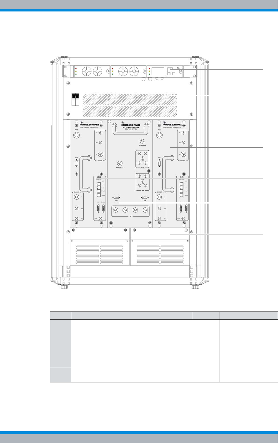
Figure 3.1 shows the front view of the DIB-500 R4.1 with four carriers. The following
table describes the components in greater detail.
Figure 3.1 DIB-500 R4.1 (front view)
Table 3.1 Legend: DIB-500 R4.1 (front view)
No. Component Number Described in
1 Voltage supply and alarming system (optional),
consisting of
|SC200 – optional (VAC or alarm system
expansion)
|Alarm input/output module – optional (VAC
or alarm system expansion)
|Rectifier module – optional (VAC expansion)
1 refer to section 3.1.1
on page 34
2 Cover including On/off switch 1 refer to section 3.1.4
on page 43
3
4
1
2
3
5
Installation, Operation and Service Manual 90DIB500R41IM_FCC02 – 99.1 33
DIB-500 R4.1 Product description
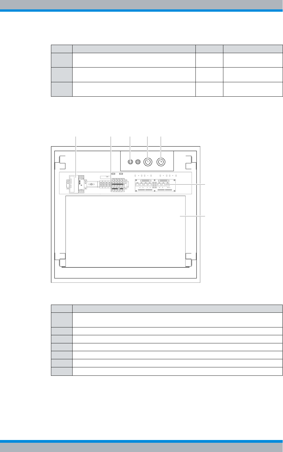
Figure 3.2 shows the top view of DIB-500 R4.1. The following table describes the com-
ponents in greater detail.
Figure 3.2 DIB-500 R4.1 without top cover (top view)
The following sections describe the functions, components, interfaces, wiring and scope
of supply of the DIB-500 R4.1.
3 TIB transceiver module (TETRA Indoor Base) 1 - 2 refer to section 3.1.5
on page 34
4 Antenna Coupling System (ACS) 1 refer to section 3.1.6
on page 54
5 Fan unit 1 - 2 refer to section 3.1.7
on page 57
Table 3.2 Legend: DIB-500 R4.1 without top cover (top view)
No. Component
1 LAN Routing Unit (LRU) with top hat rail power supply unit – optional (redundancy
package)
2 Terminal block
3 GPS antenna connector
4 TETRA antenna connection A
5 TETRA antenna connection B
6 E1 connection board
7 Mounting frame – optional (with VAC or alarm notification expansion)
Table 3.1 Legend: DIB-500 R4.1 (front view)
No. Component Number Described in
6
3 4
7
5
1 2

DIB-500 R4.1 Product description
Constituents
34 Installation, Operation and Service Manual 90DIB500R41IM_FCC02 – 99.1
3.1 Constituents
The DIB-500 R4.1 consists of the following hardware components:
|Voltage supply and alarming system
|E1 connection board
|Redundancy package with LAN Routing Unit (LRU)
|On/off switch
|TIB transceiver module (TETRA Indoor Base)
|Antenna Coupling System (ACS)
|Fan unit
|Cavity coupler (only for the Cavity variant)
3.1.1 Voltage supply and alarming system
The DIB-500 R4.1 is operated with 48 VDC in the standard version. Optionally, operation
with 100 VAC to 240 VAC is possible. Inside the equipment rack, the voltage supply is dis-
tributed via the terminal block. For a description of the terminal block, please refer to
section 3.1.1.1 on page 35.
An alarm system expansion can optionally be used for the standard version of the
DIB-500 R4.1 with VDC voltage supply, see section 3.1.1.3 on page 37. For the VAC
expansion as well as the alarm system expansion, a mounting frame with correspond-
ing hardware components is installed in the equipment rack of the DIB-500 R4.1.
Table 3.3 provides an overview of the components for the voltage supply and alarm sys-
tem of the individual versions of the DIB-500 R4.1.
The following sections describe the components of the voltage supply and alarm system
of the DIB-500 R4.1.
Table 3.3 Components for voltage supply and alarm system
Version Terminal block SC200 Alarm input/
output module Rectifier module
VDC voltage supply
(standard)
x --- --- ---
Alarm system
expansion xxx---
VAC expansion x x x x
Installation, Operation and Service Manual 90DIB500R41IM_FCC02 – 99.1 35
DIB-500 R4.1 Product description
Constituents
3.1.1.1 Terminal block
The terminal block provides terminals for connecting the VDC voltage supply and distrib-
utes the internal VDC supply in the equipment rack. Each equipment rack (except for the
Cavity variant of the Cavity equipment rack) features a separate terminal block.
Voltage supply connector for VAC voltage supply
For the VAC voltage supply, the voltage supply connector is implemented via the optional
VAC voltage supply unit, see section 3.1.1.2 on page 36.
The terminal block can be accessed from above after the upper equipment rack cover
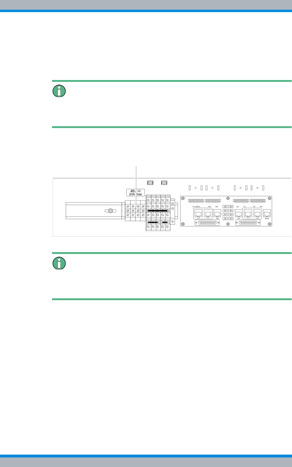
has been removed. Figure 3.3 shows a section of the top view of the DIB-500 R4.1 and
the position of the terminal block.
Figure 3.3 Position of the terminal block (top view)
Earthing connection (commissioning)
The earthing connection must be established via a threaded bolt on the frame of the
equipment rack, see section 5.6.1 on page 107.
DIB-500 R4.1 Product description
Constituents
36 Installation, Operation and Service Manual 90DIB500R41IM_FCC02 – 99.1
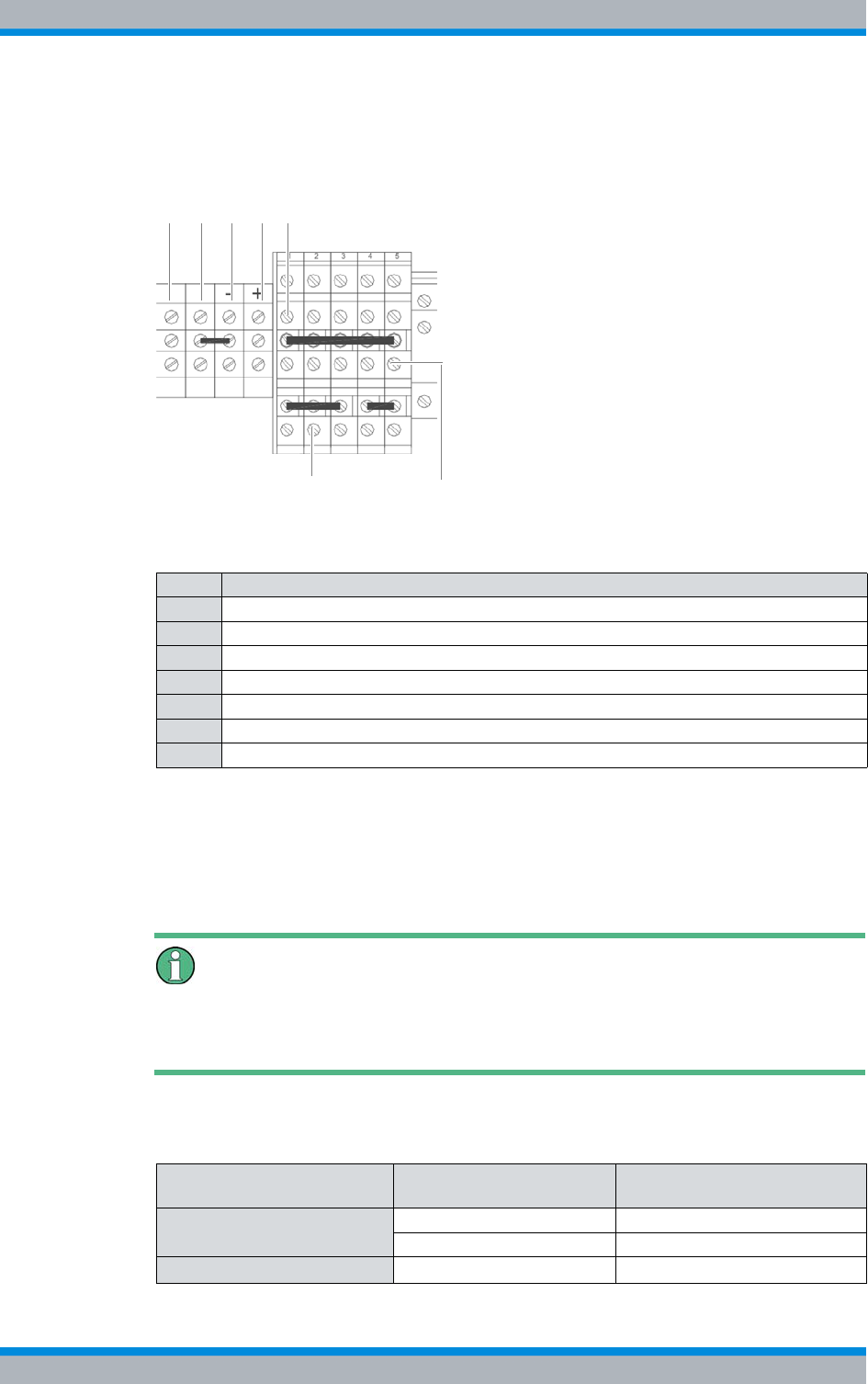
Figure 3.4 shows the top view of the terminal block in a simplified representation. The
following table describes the terminals in more detail that are required for connecting a
VDC voltage supply and top hat rail power supply unit of the redundancy package.
Figure 3.4 Terminal block
3.1.1.2 Expansion for VAC voltage supply (VAC voltage supply unit)
The VAC voltage supply unit is a hardware component and consists of different compo-
nents, see Table 3.6 on page 37. For variants of the DIB-500 R4.1 with more than four
carriers, one VAC voltage supply unit is installed for each equipment rack.
Voltage supply connector for VDC voltage supply
For a VDC voltage supply, the voltage supply connection is implemented via the terminal
block, refer to section 3.1.1.1 on page 35.
Table 3.5 describes the number of rectifier modules as a factor of the voltage supply.
Table 3.4 Legend: Terminal block
No. Wire colour
1 Terminal with earthing cable for potential equalisation
2 Terminal for connecting a negative terminal earthing
3 "-" terminal for the negative voltage supply cable
4 "+" terminal for the positive voltage supply cable
5 Terminal for connecting a positive terminal earthing
6 "+" terminal for the top hat rail power supply unit of the redundancy package
7 "-" terminal for the top hat rail power supply unit of the redundancy package
6
7
1 2 3 4 5
Table 3.5 Number of rectifier modules
Voltage supply Number of transceiver
modules Number of rectifier modules
100 VAC - 170 VAC (nominal) 1 1
22
170 VAC - 240 VAC (nominal) 2 1
Installation, Operation and Service Manual 90DIB500R41IM_FCC02 – 99.1 37
DIB-500 R4.1 Product description
Constituents
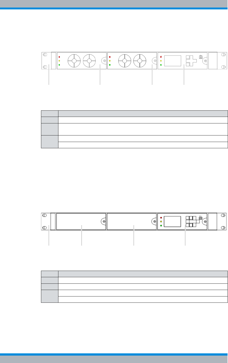
Figure 3.5 shows the front view of a VAC voltage supply unit, which provides two rectifier
modules, as an example. The following table describes the components in greater
detail.
Figure 3.5 VAC voltage supply unit (front view)
3.1.1.3 Alarm system expansion
With VDC voltage supply, the DIB-500 R4.1 can be equipped with an alarm system
expansion. With the alarm system expansion, the DIB-500 R4.1 can be expanded with
additional digital alarm inputs and outputs for external alarms. The alarm system expan-
sion is also part of the VAC expansion, see section 3.1.1.2 on page 36.
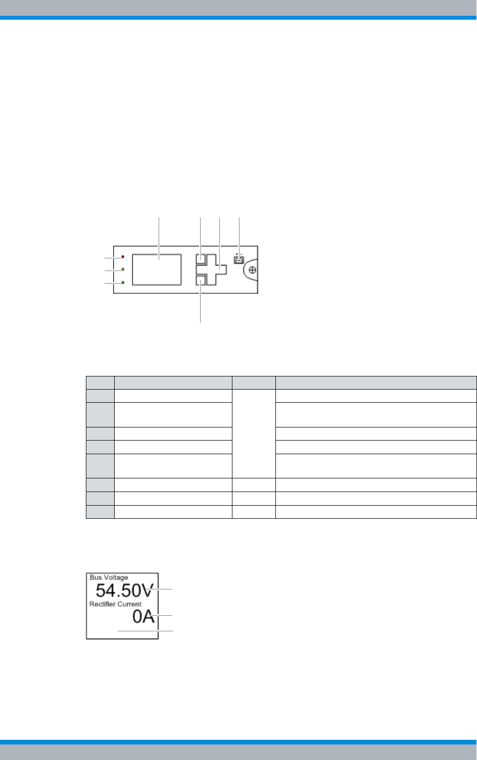
Figure 3.6 shows the front view of the alarm system expansion as an example. The fol-
lowing table describes these indicators in detail.
Figure 3.6 Alarm system expansion (front view)
Table 3.6 Legend: VAC voltage supply unit (front view)
No. Constituent
1 Mounting frame
2 Rectifier module(s), the number depends on the VAC voltage on site and on the
number of installed transceiver modules, see Table 3.5 on page 36
3SC200
Alarm input/output module (installed behind the SC200 in the mounting frame)
PSU1 PSU2
2 2 31
Table 3.7 Legend: Alarm system expansion (front view)
No. Component
1 Mounting frame
2 not used for the time being
3SC200
Alarm input/output module (installed behind the SC200 in the mounting frame)
2 2 31
DIB-500 R4.1 Product description
Constituents
38 Installation, Operation and Service Manual 90DIB500R41IM_FCC02 – 99.1
3.1.1.4 SC200 – optional (VAC or alarm system expansion)
The SC200 is a hardware component and used for monitoring the voltage supply and
for alarm signalling and is installed in the mounting frame.
Through the SC200, external alarms can be collected via the freely-configurable, digital,
alarm inputs of the alarm input / output module and reported via the Network Manage-
ment System. In addition, product alarms can be signalled via the digital alarm outputs
of the alarm input/output module.
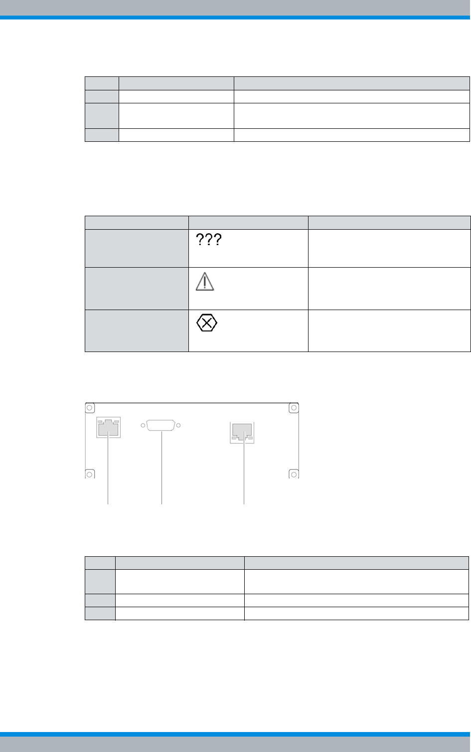
Figure 3.7 shows the front view of the system controller. The following table describes
these indicators in detail.
Figure 3.7 Front view of system controller
Figure 3.8 shows the display window of the system controller. The following table
describes these in detail.
Figure 3.8 System controller display window
Table 3.8 Legend: front view of system controller
No. Constituent Colour Description
1 Display window
---
Display window for visualization.
2 Softkey Softkey. The respective function depends on
the display in the display window.
3 Navigation keys Keys for navigation and menu inputs.
4 USB USB interface
5 Softkey Softkey. The respective function depends on
the display in the display window.
6 LED "Power" green LED for signalling of the voltage supply.
7 "Minor Alarm" LED yellow LED for signalling "minor" alarms.
8 "Critical/Major Alarm" LED red LED for signalling "major" and "critical" alarms.
21 3
5
8
7
6
4
1
2
3
Installation, Operation and Service Manual 90DIB500R41IM_FCC02 – 99.1 39
DIB-500 R4.1 Product description
Constituents
Table 3.10 provides an overview of the possible alarm states and the corresponding
alarm indicators. The visual indicators are shown on the display window of the system
controller.
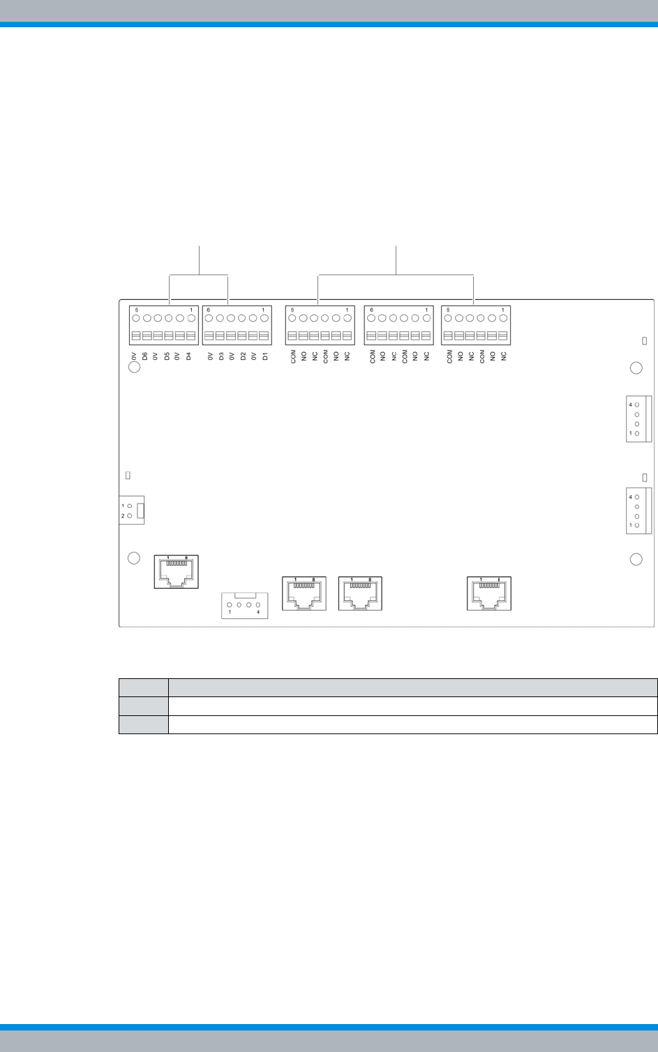
Figure 3.9 shows the rear view of the system controller. The following table describes
these in detail.
Figure 3.9 Rear view of system controller
Table 3.9 Legend: System controller display window
No. Constituent Description
1 Bus voltage The voltage of the equipment rack
2 Rectifier Current Output current of the rectifier module (with VAC-voltage
supply only)
3 Alarms Area for displaying alarms
Table 3.10 Alarm states and alarm indicators (system controller)
Alarm state Visual indicator Acoustic indicator
A state cannot be dis-
played ---
MINOR Acoustic signal every two seconds.
CRITICAL/MAJOR Continuous acoustic signal
Table 3.11 Legend: rear view of system controller
No. Constituent Description
1 Ethernet interface Ethernet interface to the first TIB of the equipment
rack (TIB A, LAN 1).
2 Serial interface not used for the time being
3 Supply voltage connection Supply voltage connection of the system controller
1 2 3
DIB-500 R4.1 Product description
Constituents
40 Installation, Operation and Service Manual 90DIB500R41IM_FCC02 – 99.1
3.1.1.5 Alarm input/output module – optional (VAC or alarm system expansion)
The alarm input/output module is a hardware component that provides the alarm con-
tacts for the digital alarm inputs/outputs. The alarm input/output module also features
alarm contacts for connecting external hardware components.
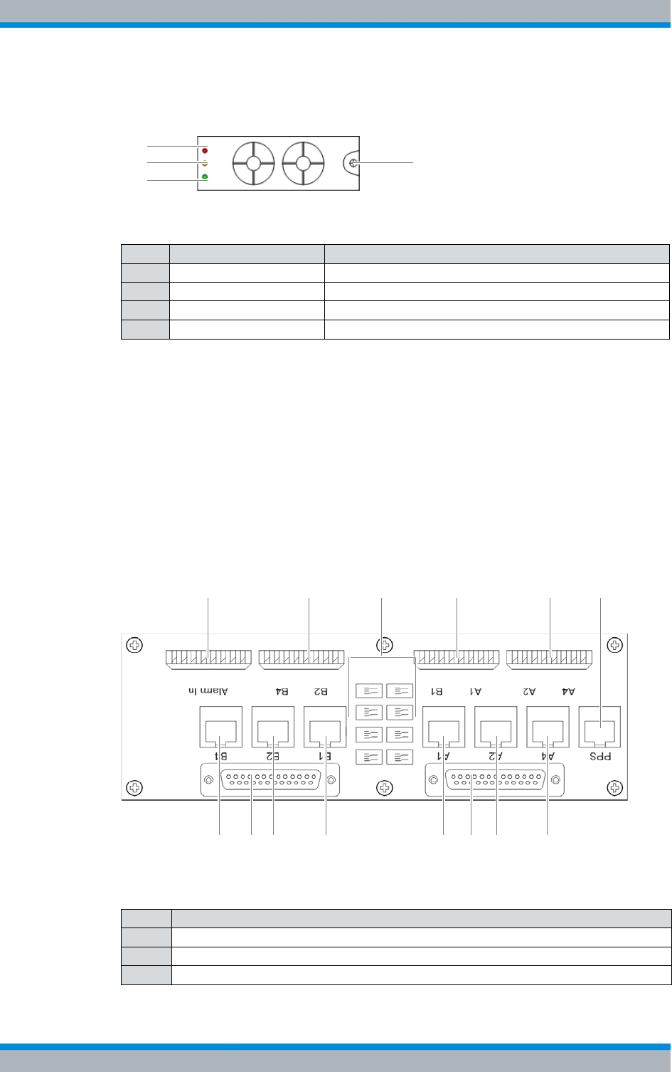
Figure 3.10 shows the alarm input/output module. The following table describes the
components in greater detail.
Figure 3.10 Alarm input/output module
3.1.1.6 Rectifier module – optional (VAC expansion)
The rectifier modules are used to supply the mounting frame and the SC200 with volt-
age.
The rectifier module is a hardware subcomponent of the power supply unit and used for
converting alternating-current voltage (VAC) into direct-current voltage (VDC).
Table 3.12 Legend: alarm input/output module
No. Component
1 Digital external alarm inputs
2 Digital external alarm outputs
1 2
Installation, Operation and Service Manual 90DIB500R41IM_FCC02 – 99.1 41
DIB-500 R4.1 Product description
Constituents
Figure 3.11 shows the front view of a rectifier module. The following table describes
these indicators in detail.
Figure 3.11 Rectifier module (front view)
3.1.2 E1 connection board
The E1 connection board provides connections for the internal and external E1 wiring
and for alarms.
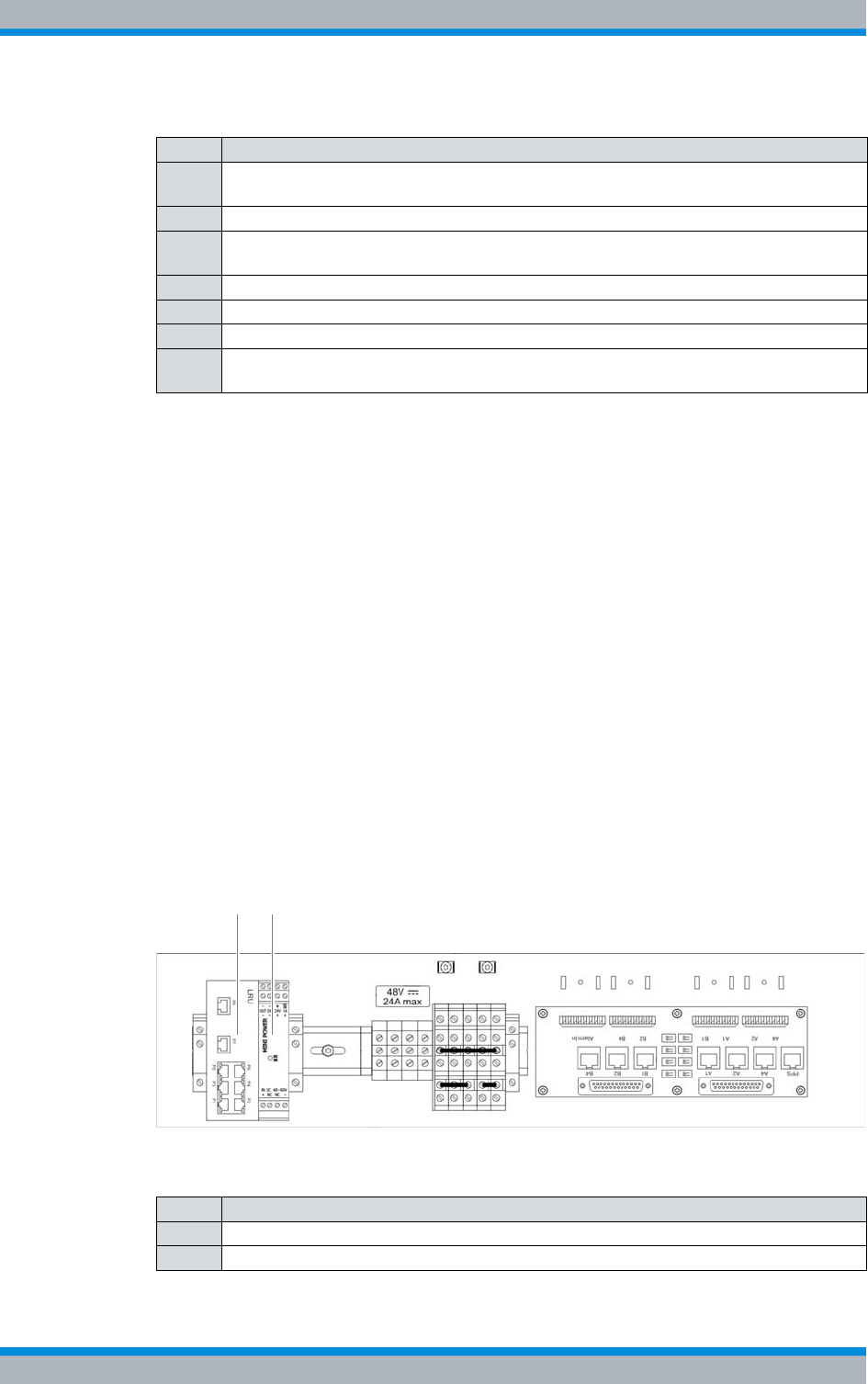
The external E1 interfaces A1 and B1 (refer to Figure 3.12, are routed via an E1 relay
and serve to connect further network elements connected in the form of a ring. If a TIB
transceiver module fails, the E1 relay is disabled and the incoming E1 connection is
directly looped on to the next network element.
Figure 3.12 shows the top view of the E1 connection board. The following table
describes these indicators in detail.
Figure 3.12 E1 connection board (top view)
Table 3.13 Legend: front view of rectifier module
No. Constituent Description
1 "Major Alarm" LED LED for signalling major alarms.
2 "Minor Alarm" LED LED for signalling "minor" alarms.
3 LED "Power" LED for signalling of the voltage supply.
4 Mounting screw ---
3
1
24
Table 3.14 Legend: E1 connection board (top view)
No. Description
1 External alarm inputs (LSA+)
2 External E1 connections (LSA+)
3 E1 relay for looping through connected E1 connections
31
10 6
2 2 2 4
557899
DIB-500 R4.1 Product description
Constituents
42 Installation, Operation and Service Manual 90DIB500R41IM_FCC02 – 99.1
3.1.3 Redundancy package with LAN Routing Unit (LRU)
The redundancy package with LAN Routing Unit (LRU), which is available as an option,
serves the base station DIB-500 R4.1 starting with five carriers for the redundant con-
nection of the TIB transceiver modules. If the redundancy package is used, all TIB
transceiver modules in both equipment racks are connected with the LAN Routing Unit
(LRU) via Ethernet. In this case, the LRU takes on the routing between the TIB trans-
ceiver modules.
With the ring-shaped connection of all transceiver modules in both equipment racks,
TIBs are connected with each other. If a TIP should fail, this guarantees that the con-
nection between the remaining TIBs continuous to be ensured. This also guarantees
the radio coverage of DIB-500 R4.1 even if the second, third or fourth TIB transceiver
module should fail.
The redundancy package consists of the LAN Routing Unit (LRU), a top hat rail power
supply unit as well as the voltage supply and Ethernet cables required for the installa-
tion. For operation, the LRU must be installed on the top hat rail on the first equipment
rack of the DIB-500 R4.1, see section 5.5.1 on page 96.
Figure 3.13 shows the position of the redundancy package in the top view.
Figure 3.13 Position of the redundancy package (top view)
4 "PPS" connection (pulses per second) for clock synchronisation of DIB-500 R4.1-
equipment racks (RJ-45)
5 External E1 connections to TIB A (RJ-45)
6 Port for connecting the E1 connecting cables from the E1 connection panel to TIB A
(D-sub)
7 External E1 port with connection to E1 relay (RJ-45)
8 External E1 port with connection to E1 relay (RJ-45)
9 External E1 connections to TIB B (RJ-45)
10 Port for connecting the E1 connecting cables from the E1 connection panel to TIB B
(D-sub)
Table 3.14 Legend: E1 connection board (top view)
No. Description
Table 3.15 Legend: Position of the redundancy package (top view)
No. Component
1LRU
2 Top hat rail power supply unit
1 2
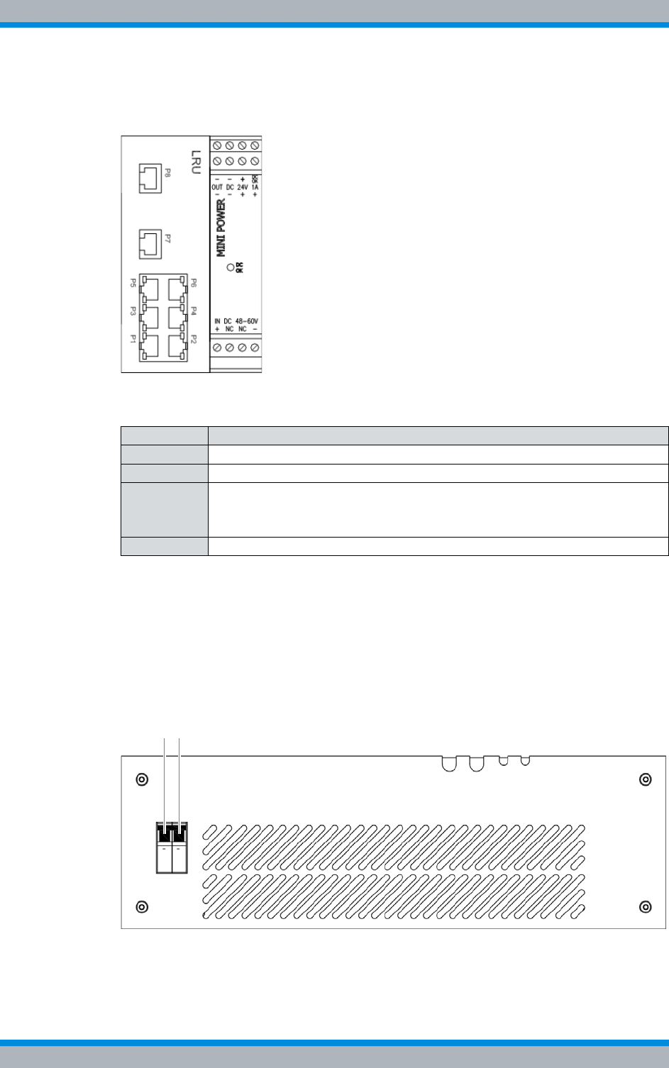
Installation, Operation and Service Manual 90DIB500R41IM_FCC02 – 99.1 43
DIB-500 R4.1 Product description
Constituents
Figure 3.14 shows the front view of the LRU, including top hat rail power supply unit.
The following table describes these indicators in detail.
Figure 3.14 LRU, including top hat rail power supply unit (top view)
3.1.4 On/off switch
Every TIB transceiver module features a separate on-off switch in the respective equip-
ment rack. The other components in the equipment cabinet are supplied with voltage
via internal connections to the terminal block.
Figure 3.15 shows the On/Off switches of the TIB transceiver modules.
Figure 3.15 On/off switch
Table 3.16 Legend: LRU, including top hat rail power supply unit (top view)
Supply Component
P1 to P4 not used for the time being
P5 TIB A (LAN 3)
P6 Connection to:
|TIB C (LAN 3) – up to six carriers
|TIB D (LAN 3) – starting with seven carriers
P7 and P8 not used for the time being
1 2

DIB-500 R4.1 Product description
Constituents
44 Installation, Operation and Service Manual 90DIB500R41IM_FCC02 – 99.1
Voltage supply of the ACS
The antenna coupling system (ACS) is supplied with voltage via the installed TIB trans-
ceiver modules. Correspondingly, the ACS is de-energised only if the On/Off switches of
all installed TIB transceiver modules have been switched off.
The following table describes the switch setting of the on/off switch.
Table 3.17 Legend: On/Off switches
No. Description
1 On/Off switches for the first TIB transceiver module and the corresponding fan
2 On/Off switches for the second TIB transceiver module and the corresponding fan
Table 3.18 Settings of the On/Off switch
Switch setting Description
Top Switched on
Bottom Switched off
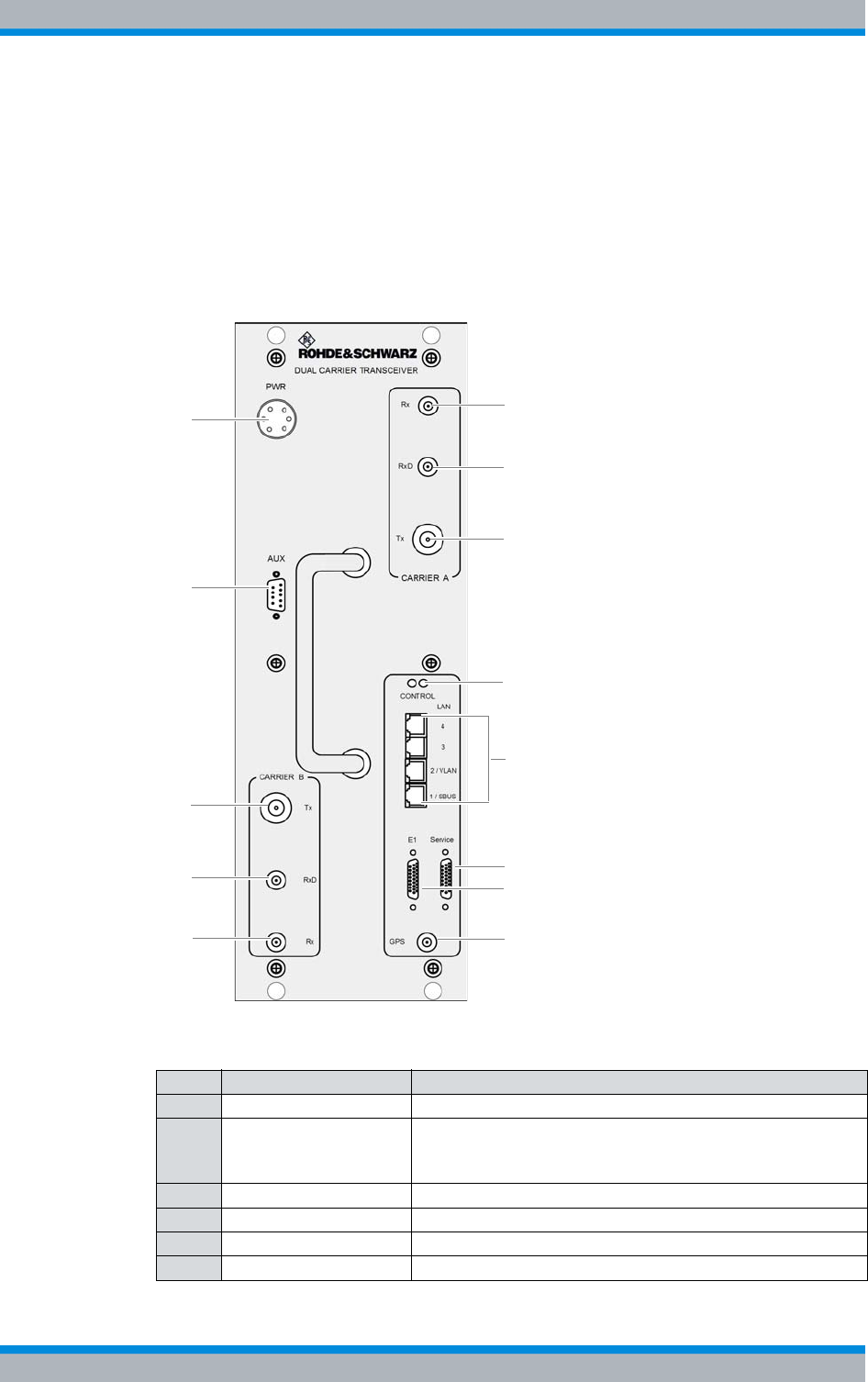
Installation, Operation and Service Manual 90DIB500R41IM_FCC02 – 99.1 45
DIB-500 R4.1 Product description
Constituents
3.1.5 TIB transceiver module (TETRA Indoor Base)
The TETRA Indoor Base transceiver module (TIB) is a hardware component. The TIB
has been implemented in the form of a subrack for the equipment rack and provides a
maximum of two carriers for the radio coverage to and from the mobile stations within
an ACCESSNET®-T IP network.
Figure 3.16 shows the front view of the TIB. The following table describes these indica-
tors in detail.
Figure 3.16 TIB (front view)
Table 3.19 Legend: TIB (front view)
No. Supply Description
1 PWR 48 VDC voltage supply connection
2 AUX Interface to the antenna coupling system including voltage
supply and VSWR (Voltage Standing Wave Ratio) evalua-
tion.
3 Tx (Carrier B) Tx transmitter output carrier B
4 RxD (Carrier B) Rx receiver input carrier B (Diversity)
5 Rx (Carrier B) Rx receiver input carrier B
6 Rx (Carrier A) Rx receiver input carrier A
1
2
3
4
5
7
6
8
9/10
12
13
14
11
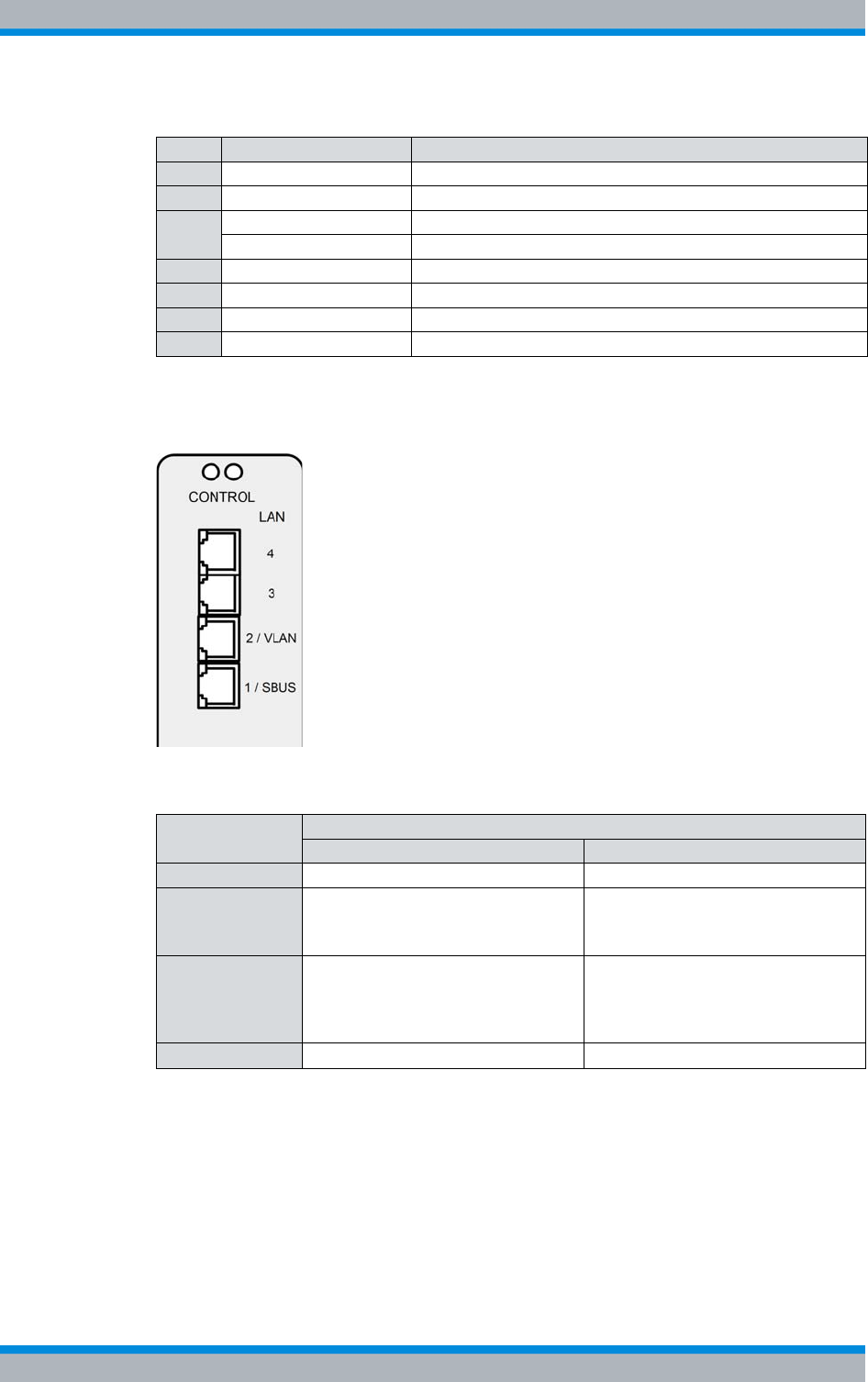
DIB-500 R4.1 Product description
Constituents
46 Installation, Operation and Service Manual 90DIB500R41IM_FCC02 – 99.1
Figure 3.17 shows the Ethernet port of the TIB. The following table describes these indi-
cators in detail.
Figure 3.17 TIB Ethernet ports
7 RxD (Carrier A) Rx receiver input carrier A (Diversity)
8 Tx (Carrier A) Tx transmitter output carrier A
9/10 Power LED (LH side) Voltage supply status indicator
Alive LED (RH side) Operation status indicator
11 Ethernet ports Described in Table 3.20 on page 46
12 Service Serial service interface
13 E1 E1 interface to E1 connection board of the DIB-500 R4.1
14 GPS GPS antenna connector
Table 3.20 Legend: TIB Ethernet ports
Name of con-
nection Description
TIB A TIB B
LAN (4) |Connection with TIB B |Connection with TIB A
LAN (3) |Connection with an additional
equipment rack1)
|Connection with the LRU2)
1) in variants starting at five carriers
2) if installed in the second equipment rack, in variants starting at five carriers
|Connection with the LRU2)
LAN (2/VLAN) |Connection of the service com-
puter (local)
|Connection to an IP transport
network or a layer-3 switch
|Connection of the service com-
puter (local)
|Connection to an IP transport
network or a layer-3 switch3)
3) with controller redundancy (optional) in variants with two TIB transceiver modules with
two carriers each
LAN (1/SBUS) |Connection to the SC2004)
4) only for VAC or alarm system expansion
|not used for the time being
Table 3.19 Legend: TIB (front view)
No. Supply Description
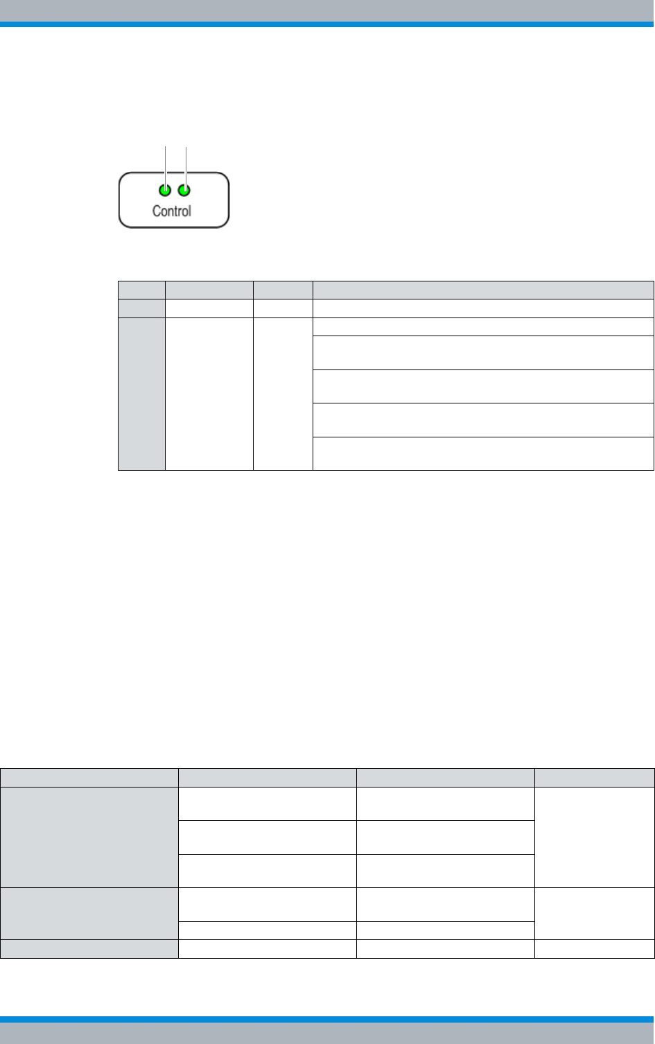
Installation, Operation and Service Manual 90DIB500R41IM_FCC02 – 99.1 47
DIB-500 R4.1 Product description
Constituents
Figure 3.18 shows the indicators of the TIB. The following table describes these indica-
tors in detail.
Figure 3.18 TIB indicators
3.1.5.1 Overview of possible functions and corresponding software components on the
TIB transceiver module
Besides the provisioning of the base station function (BSF), the DIB-500 R4.1 can take
on the switching controller function (SCF) in ACCESSNET®-T IP networks with distrib-
uted switching architecture. In addition, the DIB-500 R4.1 is participating in the imple-
mentation of additional functions in the ACCESSNET®-T IP depending on the network
configuration.
Table 3.22 provides an overview of the functions that can be provided via the
DIB-500 R4.1. In addition, the software components required for providing the respec-
tive function and the corresponding hardware component are listed within the trans-
ceiver module on which the respective software component is installed. The distribution
of the software components onto the hardware components is represented in Figure
3.19 on page 48.
Table 3.21 Legend: Indicators (LEDs) of the TIB
No. LED Colour Description
1 Power- LED green lights up during operation
2 Alive-LED green flashes rapidly (100/100 ms) when the voltage supply fails
flashes every half second (500/500 ms) when PowerPC
and IntelPC are in operation (standard operation)
flashes every second (1000/1000 ms) when PowerPC and
IntelPC are shut down (Shutdown initiated)
flashes every 2 seconds (2000/2000 ms) when the operat-
ing temperature is too high or too low
flashes every 3 seconds (3000/3000 ms) when PowerPC
and IntelPC have been shut down (Shutdown completed)
2
1
Table 3.22 Functions and corresponding software components on the TIB transceiver module
Function Software component Hardware component Described on
Base Station Function (BSF) Coder/decoder software Receiver/transmitter unit
(transceiver) Page 49
TETRA Operation Server
(TOS) IntelPC
Processing Unit Controller
(PUC) Multi Processor Server Unit
(MSU)
Switching Controller Function
(SCF) Core Operation Server
(COS) IntelPC Page 49
IP Switch (IPS) IntelPC
Telephony Gateway (TGW) SIP Media Gateway (SMG) IntelPC Page 50
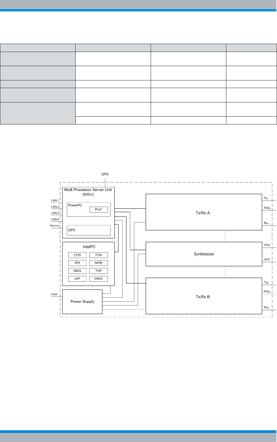
DIB-500 R4.1 Product description
Constituents
48 Installation, Operation and Service Manual 90DIB500R41IM_FCC02 – 99.1
Figure 3.19 shows the block diagram of the TIB in simplified representation in a variant
with two carriers and with all available functions or software components.
Figure 3.19 TIB block diagram
Application Gateway (AGW) TETRA Application Platform
(TAP) IntelPC Page 50
TETRA Vocoder Function
(TVF) SIP Media Gateway (SMG) IntelPC Page 49
Packet Data Gateway (PGW) Packet Data Server (PDS) IntelPC Page 50
Configuration management1) Network Element Manager
(NEM-523) IntelPC Page 52
Hardware monitoring Processing Unit Controller
(PUC) Multi Processor Server Unit
(MSU) Page 51
Hardware Guard (HWG) IntelPC Page 53
1) The Configuration Management is provided as administrative function via the network management system
NMS-500.
Table 3.22 Functions and corresponding software components on the TIB transceiver module
Function Software component Hardware component Described on

Installation, Operation and Service Manual 90DIB500R41IM_FCC02 – 99.1 49
DIB-500 R4.1 Product description
Constituents
3.1.5.2 Overview of possible functions
In the ACCESSNET®-T IP, the available services and performance features are com-
bined in form of so-called functional units. These functional units available for the
present product are described in the following sections.
Depending on the respective network configuration, the DIB-500 R4.1 can provide the
following functional units:
|Base Station Function (BSF)
|Switching Controller Function (SCF)
|TETRA Vocoder Function (TVF)
|Application Gateway (AGW)
|Packet Data Gateway (PGW)
|Telephony Gateway (TGW)
Base Station Function (BSF)
The Base Station Function (BSF) is a functional unit of the ACCESSNET®-T IP and pro-
vides the air interface in compliance with the TETRA standard (Terrestrial Trunked
Radio, TETRA).
The air interface facilitates the communication (voice and data) between mobile stations
such as hand-held mobile radios, data radios (Remote Terminal Unit, RTU) and radio
dispatcher workstations. The radio channels for this purpose are generated via trans-
ceivers of the base stations that are available in various frequency ranges. The traffic
and packet data channels are dynamically occupied. Signalling and short messages
(SDS) are transmitted via statically configured control channels (MCCH and, if neces-
sary, SCCH).
Switching Controller Function (SCF)
The Switching Controller Function (SCF) is a centralised function block of the
ACCESSNET®-T IP and ensures the IP-based routing function between the network
constituents of an ACCESSNET®-T IP network and the gateways (telephone network,
application and packet data).
The SCF can be used flexibly on different network elements/platforms and combined
with other functional units. If a distributed switching architecture is used in an
ACCESSNET®-T IP network, gateways to applications could be implemented locally at
any network constituents. Depending on the requirements of the ACCESSNET®-T IP
network, the routing functions are also available to application and telephone gateways.
TETRA Vocoder Function (TVF)
The TETRA Vocoder Function (TVF) serves as a converter (encoder/decoder) for voice
streams between the TETRA system and an external system such as a telephone net-
work. With the aid of the TVF, the voice between the TETRA format used (ACELP, Alge-
braic Code Excited Linear Prediction) and the G.711 format (A-Law or µ-Law) is
recoded. The TVF is required for the Telephone Gateway (TGW) functional unit. The
TVF is also required for the Application Gateway (AGW) functional unit if the voice con-
nection of the application is to be implemented via G.711 instead of via the TETRA
codecs.

DIB-500 R4.1 Product description
Constituents
50 Installation, Operation and Service Manual 90DIB500R41IM_FCC02 – 99.1
Application Gateway (AGW)
The Application Gateway (AGW) facilitates the communication between the
ACCESSNET®-T IP network and applications that use the services of the TETRA sys-
tem such as dispatchers, positioning systems (AVL, GIS), voice and data recording as
well as SCADA or SMART-Metering applications.
Packet Data Gateway (PGW)
The packet data service facilitates the efficient transmission of packet data between
mobile stations within a ACCESSNET®-T IP network and to connected IP networks.
Possible application scenarios are e.g. database queries or the transmission of data to
control systems (SCADA, Supervisory Control and Data Acquisition).
The Packet Data Gateway (PGW) provides the packet data gateways for mobile sta-
tions. This packet data gateway provides access points for accessing connected IP net-
works of various user organizations.
Telephony Gateway (TGW)
The TGW provides an IP-based telephone gateway between the ACCESSNET®-T IP
network and an appropriate VoIP private automatic branch exchange.
Within the ACCESSNET®-T IP network, the TGW is logically connected to the Switch-
ing Controller Function (SCF). The signalling of the TGW for the registration and call
control with the telephone system is performed according to the SIP standard (Session
Initiation Protocol). The Real-time Transport Protocol (RTP) is used as the transmission
protocol for the voice. The voice itself is encoded in the G.711 format (A-law or µ-law).
3.1.5.3 Multi Processor Server Unit (MSU)
The MSU is a hardware component. It serves as a hardware platform for the Processing
Unit Controller (PUC) software component. It provides four Ethernet interfaces.
In addition, a GPS module is installed in the MSU that is responsible for providing the
clock and time reference signals (synchronization) required for switching connections.
The MSU components are described in detail in the following sections.
PowerPC
The PowerPC is a hardware component and distributes the GPS reference signal,
which it receives from the GPS module, to the IntelPC with the help of the Network Time
Protocol (NTP). If connected network elements, such as an IP node (IPN), do not fea-
ture their own GPS reference signal, they can be supplied with the GPS time via the
PowerPC of the DIB-500 R4.1. In addition, the PowerPC serves as hardware platform
for the software component Processing Unit Controller (PUC).

Installation, Operation and Service Manual 90DIB500R41IM_FCC02 – 99.1 51
DIB-500 R4.1 Product description
Constituents
Processing Unit Controller (PUC)
The Processing Unit Controller (PUC) is a software component and serves for commis-
sioning, configuring, controlling and monitoring the integrated hardware components of
the TIB. The PUC makes the resulting data available to the Network Management Sys-
tem via an SNMP agent.
The PUC is also responsible for the signalling between the transceivers and the TETRA
Operation Server (TOS). The PUC forwards the signalling from the transceivers to the
TOS or, the signalling from the TOS via the air interface back to the transceivers.
GPS module
The GPS module (Global Positioning System, GPS) is a hardware component within
the MSU and ensures the provisioning of the reference signals for clock and time that
are required for the synchronisation of the components within the network element. For
this purpose, the time signal received from the PUC software component is processed
and forwarded to the PowerPC as a reference signal. From there, the reference signal
is distributed with the aid of the Network Time Protocol (NTP).
3.1.5.4 IntelPC
The IntelPC is a hardware component and, depending on the network configuration,
serves as hardware platform for the following software components:
|Core Operation Server (COS)
|TETRA Operation Server (TOS)
|IP Switch (IPS)
|Network Element Manager (NEM-523)
|Packet Data Server (PDS)
|TETRA Application Platform (TAP)
|SIP Media Gateway (SMG)
|Hardware Guard (HWG)
Core Operation Server (COS)
The Core Operating Server (COS) is a software component which performs all calcula-
tions and control for exchange processes of higher protocol layers. Apart from the
switching process, this includes the call administration, the authorisation validation and
- if applicable - the resources management for the communication with other network
elements within an ACCESSNET®-T IP network. In addition the COS assumes the con-
trol of the software component IP switch.
TETRA Operation Server (TOS)
The TETRA Operation Server (TOS) is responsible for the mobility management (regis-
tration, group handling, authentication and call management with speaker monitoring,
etc.). In addition, the TOS is responsible for the resource management for the radio
channels and manages the TETRA radio cell including control of the broadcast data.

DIB-500 R4.1 Product description
Constituents
52 Installation, Operation and Service Manual 90DIB500R41IM_FCC02 – 99.1
IP Switch (IPS)
The IP Switch (IPS) is a software component. It serves for distributing TETRA voice
data between software components and to external applications (optional) and is thus a
central control component of the network element.
The TETRA voice data are received in the form of IP data packages. The received IP
data packages information facilitating the routing of the IP data packages in addition to
the TETRA voice data. The IPS is controlled by the Core Operation Server (COS) soft-
ware component via the PUC Switch (Processing Unit Controller, PUC) protocol. The IP
data packages are transferred by the IPS via point-to-point connections ("Unicast").
Network Element Manager (NEM-523)
The Network Element Manager (NEM-523) is a software component and part of the
Network Management System of ACCESSNET®-T IP. It administers the network ele-
ments and enables access to the network components of the TETRA infrastructure
installed in it.
In addition, the NEM-523 performs operative functions such as the redundancy man-
agement: if specific network resources are temporarily unavailable, the application will
control the software component by switchover to standby resources.
The NEM-523 is responsible for management functions, and controls downloads as well
as the distribution of network resources. The NEM-523 is the remote station via which
the NMC-522 DownloadManager communicates while downloading software or a con-
figuration. It is responsible for properly enabling a configuration or software and for a
fallback to the previous configuration or software version in the case of faults.
Packet Data Server (PDS)
The Packet Data Server (PDS) is a software component and provides the packet data
service. The packet data service enables an efficient transmission of packet data
between mobile stations within an ACCESSNET®-T IP network and to externally con-
nected IP networks. In this case, the PDS is the access point to one or several networks
of user organisations for mobile stations in the ACCESSNET®-T IP. For this purpose,
the PDS provides an IP gateway (Access Point Gateway, APG) for each user network,
whereby a user network is always mapped by an APG and identified by a unique
Access Point Name Index (APNI).
Due to the use of virtual networks (Virtual Private Network, VPN), the operation of multi-
ple user organisations is possible in one mobile network independently of one another.
Via IP gateways (Access Point Gateways [APG]), access to IP networks can be admin-
istered subscriber-specifically with the aid of the network management client NMC-512
SubscriberManager to configure the use of Internet and Intranet.
The packet data service can coexist with existing calls and Short Data Services (SDS)
of the ACCESSNET®-T IP. Depending on the mobile station used in each case and the
configured call priorities, the packet data transmission is not interrupted by calls.
The Packet Data Gateway (PGW) or the PDS can be operated redundantly to increase
the availability. With this type of characteristic, the ACCESSNET®-T IP network gener-
ally contains two PDS on different network elements. Up to three PDS are currently
being supported for each ACCESSNET®-T IP network.

Installation, Operation and Service Manual 90DIB500R41IM_FCC02 – 99.1 53
DIB-500 R4.1 Product description
Constituents
TETRA Application Platform (TAP)
The TETRA Application Platform (TAP) is a software component and acts as the gate-
way between applications and the ACCESSNET®-T IP. The TAP is responsible for log-
ging in/authenticating the relevant applications and connecting them to the wireless
network.
Applications can be integrated into the TAP via the ACCESSNET®T Common Applica-
tion Programming Interface (A-CAPI). The TAP forwards the data, processed, to the
core operation server (COS), for example, and thereby establishes the connection
between applications and the radio network. Via the connection with the TAP, the
respective application can be integrated into the ACCESSNET®-T IP like a radio sub-
scriber and, e.g., send short message (SDS), establishing and answering calls, etc.
A-CAPI applications connected via the TAP have a larger scope of functions than radio
subscribers such as:
|combining dynamic groups,
|administering dynamic object addresses (OOCA),
|administering dynamic call lines
|monitoring stations
|recording extended time calls (voice recorder).
Examples of A-CAPI applications:
|dispatcher,
|Voice recorder,
|SDS recorder,
|Control workstation
|Object call server.
SIP Media Gateway (SMG)
The SIP Media Gateway (SMG) is a software component and used for connecting SIP-
based private automatic branch exchange (PABX). The SMG converts TETRA-coded
voice data to G.711 and back to facilitate the communication between TETRA subscrib-
ers and private branch exchange subscribers. For the communication with PABX, the
SMG uses the standardised Session Initiation Protocol (SIP). In this function, the SMG
is used as an SIP client.
Hardware Guard (HWG)
The Hardware Guard (HWG) is a software component and is used for monitoring the
IntelPC.
3.1.5.5 Synthesiser
The synthesiser is a hardware component and provides all the required clock pulses
and frequencies. These are based on the standard clock pulse (GPS) provided by the
GPS module of the Multi Server Processor Unit (MSU). The synthesiser is used to gen-
erate and analyse the 1PPS signal (pulses per second, PPS). The synchronisation of
additional TIB transceiver modules of a DIB-500 R4.1 is performed in this way.

DIB-500 R4.1 Product description
Constituents
54 Installation, Operation and Service Manual 90DIB500R41IM_FCC02 – 99.1
3.1.5.6 Power supply
The voltage supply (Power Supply) is a hardware component and provides the voltage
supply for the TIB.
3.1.5.7 Receiver/transmitter unit (transceiver)
A carrier is a hardware component consisting of a transmitter, a receiver and a TETRA
protocol coder/decoder. Carriers are available in different frequency ranges as required.
Up to two carriers can be installed in one TIB. One carrier generates the radio channel,
via which the base station and the mobile terminal equipment exchange user data and
signalling data.
3.1.6 Antenna Coupling System (ACS)
The antenna coupling system (ACS) is a hardware component for the DIB-500 R4.1
base station. The ACS has been implemented in the form of a subrack for the equip-
ment rack and enables different antenna coupling variants.
In the hybrid variant, an ACS allows operating two or four carriers using one Tx/Rx
antenna. In the high power variant, one or two carriers are optionally available. In case
of two carriers, the operation utilises two Tx/Rx antennas. For operating more than four
carriers, two ACS (integrated in two equipment carriers) can be connected with one
another so that up to eight carriers on two Tx/Rx antennas are possible.
In the FlexibleTx variant, antenna coupling was performed project-specifically according
to the desires and requirements of the network operator via external antenna coupling
systems. In this way, the DIB-500 R4.1, e.g. can be connected to existing antenna cou-
pling systems.
Requirements for external antenna coupling systems.
The requirements on external antenna coupling systems are described in the site
requirements.
The DIB-500 R4.1 is available with different antenna coupling systems. The selection of
the corresponding antenna coupling system depends on the network requirements.
The following antenna interfaces are available for different network requirements:
|Hybrid variant
– Compact design
– As many as eight carriers per network element (two equipment racks with four
carriers each)
– Highly flexible in the frequency selection
– flexible frequency change
|Cavity variant
– As many as eight carriers per network element (two equipment racks with four
carriers each)
– higher transmitting power than hybrid variant
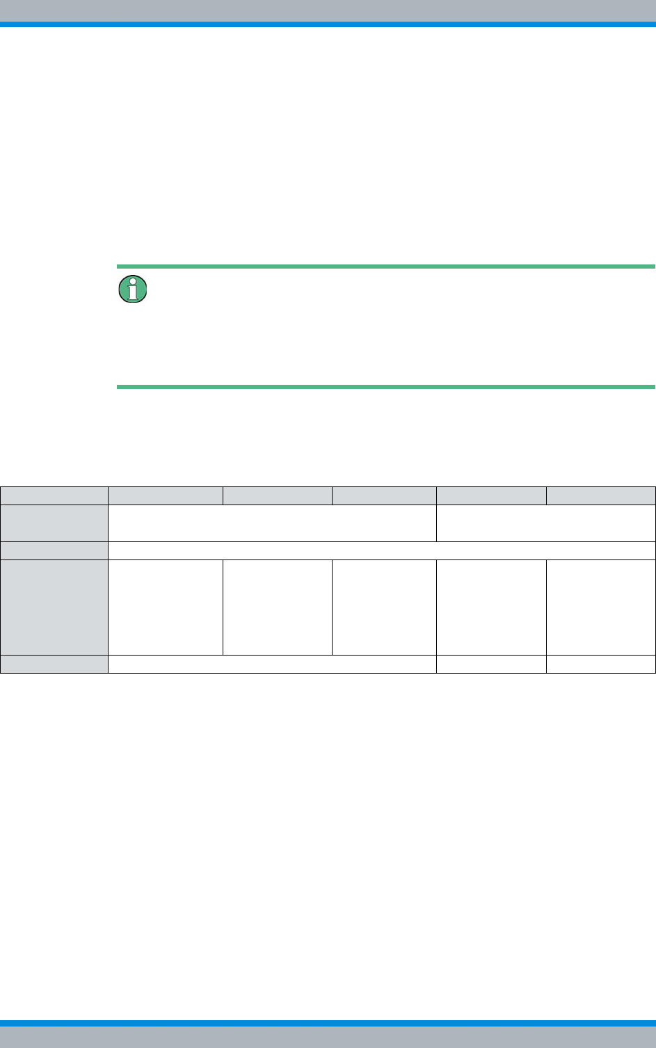
Installation, Operation and Service Manual 90DIB500R41IM_FCC02 – 99.1 55
DIB-500 R4.1 Product description
Constituents
|High power variant
– up to two carriers per network element,
– Higher transmitting power than hybrid and cavity variants
|FlexibleTx variant
– only equipped with Rx path
– up to four carriers per network element,
– high flexibility due to the use of project-specific antenna coupling systems
– site-specific provision by the network operator
Antenna diversity is available for optimal reception properties.
Additional Information
For more information on the technical characteristics and performance features of the
different versions, please refer to the Technical data. The requirements on external
project-specific antenna coupling systems are available in the site requirements.
Table 3.23 lists the antenna coupling variants, the number of carriers each variant pro-
vides and the resulting number of supported Tx/Rx antennas. For the diversity variants,
the diversity reception is facilitated by means of another Rx antenna.
Table 3.23 Variants of the ACS
Variant 1 carrier 2 carriers 3/4 carriers 5/6 carriers 7/8 carriers
Hybrid |1 Tx/Rx antenna (antenna A)1)
|1 Rx antenna (antenna B)2)
|1 Tx-/Rx antenna (antenna A)1)
|1 Rx antenna (antenna B)2)
Cavity like the hybrid variants but a single-carrier variant is not available
High Power
(without trans-
mitter coupling
system)
|1 Tx/Rx
antenna
(antenna A)
|1 Rx antenna
(antenna B)2)
|1Tx/Rx
antenna
(antenna A)
|1Tx/Rx
antenna
(antenna B)
--- --- ---
FlexibleTx depending on the antenna coupling system used --- ---
1) per equipment rack
2) with diversity
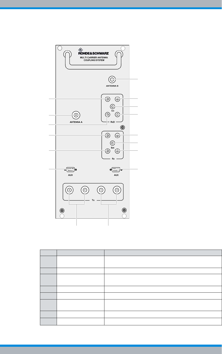
DIB-500 R4.1 Product description
Constituents
56 Installation, Operation and Service Manual 90DIB500R41IM_FCC02 – 99.1
Figure 3.20 shows the front view of the ACS. The following table describes the compo-
nents in greater detail.
Figure 3.20 ACS (front view)
Table 3.24 Legend: ACS (front view)
No. Supply Description
1 RxD (TIB A1) Antenna B Rx output carrier TIB A1 (only in the case of
diversity)
2 Antenna A Antenna A Tx/Rx antenna connection
3 RxD (TIB A2) Antenna B Rx output carrier TIB A2 (only in the case of
diversity)
4 Rx (TIB A1) Antenna A Rx output carrier TIB A1
5 Rx (TIB A2) Antenna A Rx output carrier TIB A2
6 AUX (TIB A) Interface to the TIB A transceiver module (including voltage
supply)
7 Tx (TIB A1/2)Antenna A1) Tx inputs carrier TIB A1/2
8 Tx (TIB B1/2)Antenna A1) Tx inputs carrier TIB B1/2
9
6
8
14
11
16
2
15
10
134
5
1
3
7
12
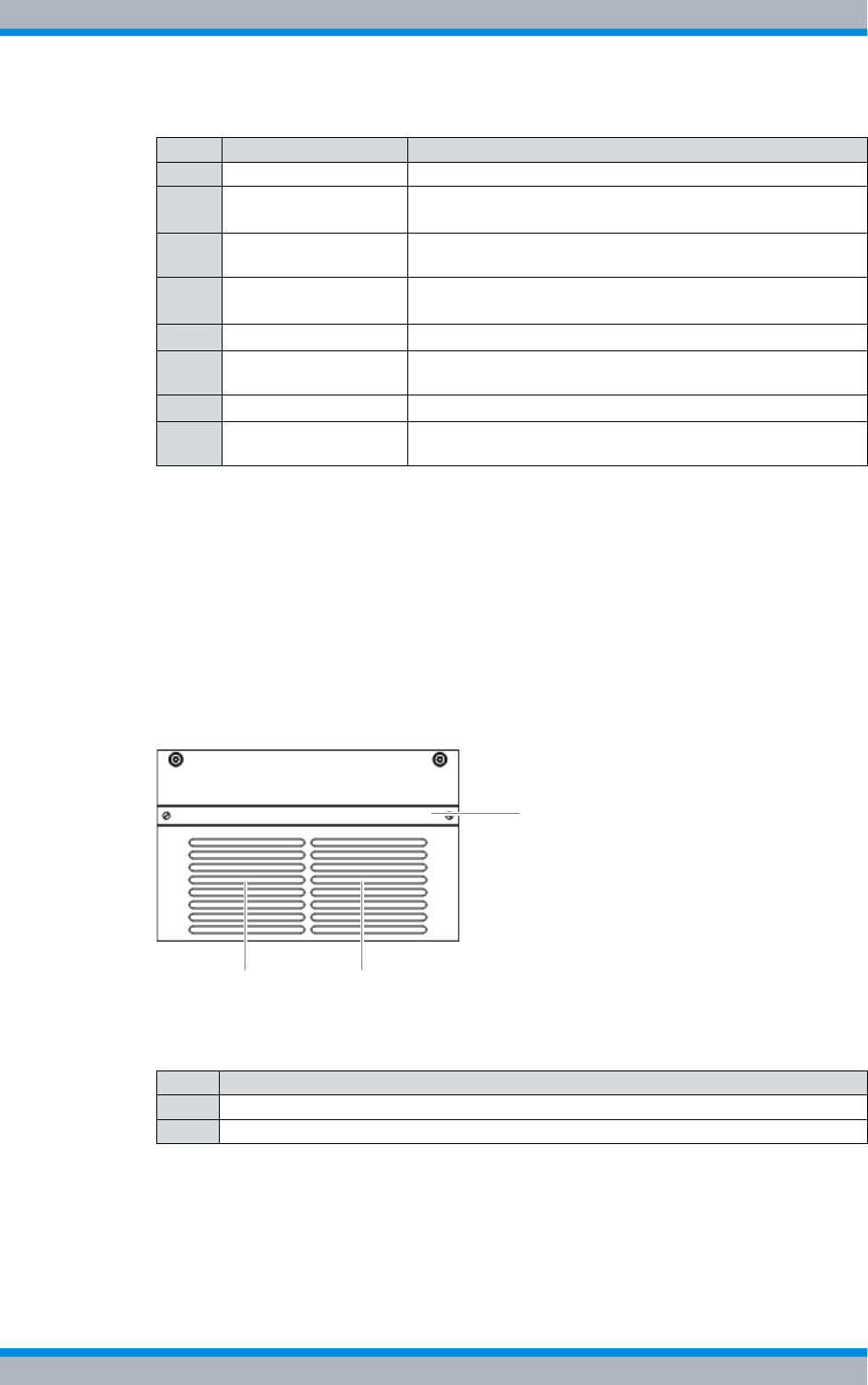
Installation, Operation and Service Manual 90DIB500R41IM_FCC02 – 99.1 57
DIB-500 R4.1 Product description
Constituents
3.1.7 Fan unit
The fan unit is a hardware component and consists of one fan subrack per TIB trans-
ceiver module. The fan unit serves for optimum vertical venting of the constituents
installed inside the equipment cabinet and for filtering the dirt and dust particles con-
tained in the air. A fan subrack is made up of a fan and an air filter pad.
Figure 3.21 shows the front view of the fan subrack. The following table describes these
indicators in detail.
Figure 3.21 Front view of fan subrack
9 Antenna B Antenna B (Tx)/Rx antenna connection
10 RxD (TIB B1) Antenna B Rx output carrier TIB B1 (only in the case of
diversity)
11 RxD Ext Interface (input) for connecting the reception paths of
another ACS for diversity reception (with > 4 carriers)
12 RxD (TIB B2) Antenna B Rx output carrier TIB B2 (only in the case of
diversity)
13 Rx (TIB B1) Antenna A Rx output carrier TIB B1
14 Rx Ext Antenna A interface (output) for connecting another ACS
(with >4 carriers)
15 Rx (TIB B2) Antenna A Rx output carrier TIB B2
16 AUX (TIB B) Interface to the TIB B transceiver module (including voltage
supply)
1) depending on the ACS variant
Table 3.24 Legend: ACS (front view)
No. Supply Description
Table 3.25 Legend: front view of fan subrack
No. Constituent
1Air intake
2 Air filter pad holder including air filter pad
1 1
2
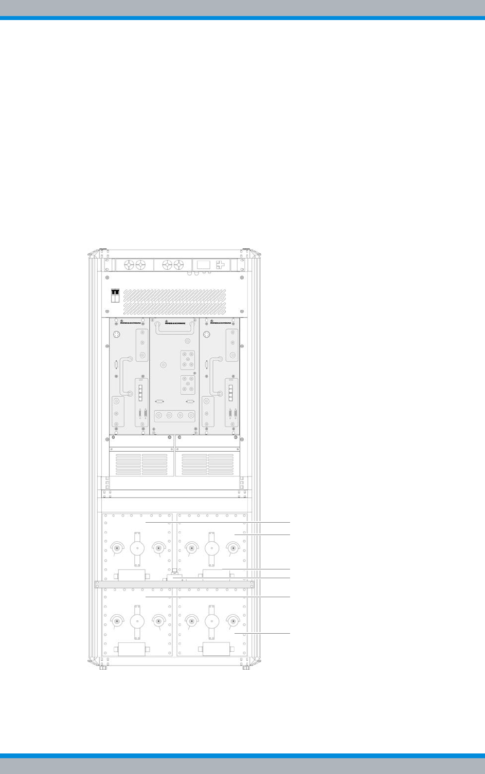
DIB-500 R4.1 Product description
Constituents
58 Installation, Operation and Service Manual 90DIB500R41IM_FCC02 – 99.1
3.1.8 Cavity coupler (only for the Cavity variant)
The cavity coupler is a hardware component and used for lossless coupling of two to
four radio channels on one transmitting antenna. Cavity couplers are available in the
cavity variant of the DIB-500 R4.1 in a separate equipment rack which can accommo-
date up to four cavity couplers. One cavity coupler is available for each carrier.
The size of the cavity couplers depends on the frequency used, e.g. smaller cavity cou-
plers are used for frequencies >806 MHz that for frequencies <486 MHz. Accordingly,
the DIB-500 R4.1 employs different cavity couplers, which vary in size, depending on
the frequencies used.
Figure 3.22 shows the DIB-500 R4.1 in the cavity variant for frequencies < 486 MHz.
The four cavity couplers are installed in a separate equipment rack. Both equipment
racks are already stacked and wired upon delivery.
Figure 3.22 DIB-500 R4.1 cavity variant with four cavity couplers for frequencies
<
486 MHz (front
view)
2
1
6
5
3
4
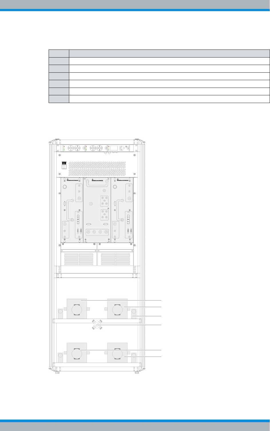
Installation, Operation and Service Manual 90DIB500R41IM_FCC02 – 99.1 59
DIB-500 R4.1 Product description
Constituents
Figure 3.23 shows the DIB-500 R4.1 in the cavity variant for frequencies > 806 MHz.
The four cavity couplers are installed in a separate equipment rack. Both equipment
racks are already stacked and wired upon delivery.
Figure 3.23 DIB-500 R4.1 cavity variant with four cavity couplers for frequencies
>
806 MHz (front
view)
Table 3.26 Legend: DIB-500 R4.1 cavity variant with four cavity couplers for frequencies < 486 MHz
(front view)
No. Designation
1 Cavity coupler A
2 Cavity coupler B
3 Insulator for cavity coupler B
4 Star distributor
5 Cavity coupler C
6 Cavity coupler D
2
1
3
4
6
5

DIB-500 R4.1 Product description
Constituents
60 Installation, Operation and Service Manual 90DIB500R41IM_FCC02 – 99.1
3.1.9 Redundancy options for the DIB-500 R4.1 or the Base Station Func-
tion (BSF)
The ACCESSNET®-T IP provides numerous redundancy concepts to ensure the availa-
bility of services and performance features reliably even in exceptional situations. The
concept of designing system functions, network elements and connection routes redun-
dantly, may be required to ensure location reliability and system reliability. Location and
system reliability refers to the capability of the network to perpetuate the operation of
the overall system even if one location or route drops out completely or partially (due to
technical failure, natural phenomena, acts of terrorism etc.).
In combination with the flexible network architecture, the design of the engineered sys-
tem permits scalable redundancy solutions that take into account the different require-
ments for availability and capacity within an overall network.
The following sections describe the available redundancy options in conjunction with
the DIB-500 R4.1.
3.1.9.1 Redundant Main Control Channel (MCCH)
Irrespective of the number of carriers assigned to a radio cell of a base station, a radio
cell has only one main control channel (MCCH), via which the mobile stations receive
information on adjacent radio cells, for example.
Generally, the main control channel is sent via the first carrier of a base station. The
three remaining channels of this carrier and all the channels of all the other carriers are
used as voice channels. Up to three of the remaining channels on the first carrier can be
configured as secondary control channels (SCCH), which reduces the number of voice
channels accordingly.
Multiple radio cells per base station
If a base station has been assigned multiple radio cells, it is also possible to configure
secondary control channels on the first carriers of these radio cells. A base station can
be assigned a maximum of four radio cells, i.e. for base station with eight carriers, a
max. of 16 control channels are possible.
Table 3.27 Legend: DIB-500 R4.1 cavity variant with four cavity couplers for frequencies > 806 MHz
(front view)
No. Designation
1 Cavity coupler A
2 Cavity coupler B
3 Insulator for cavity coupler B
4 Star distributor
5 Cavity coupler C
6 Cavity coupler D

Installation, Operation and Service Manual 90DIB500R41IM_FCC02 – 99.1 61
DIB-500 R4.1 Product description
Constituents
The main control channel can be configured redundantly on any available carrier. If the
carrier that provided the main control channel last drops out, an alternative carrier will
take on this task. In this case, the replacement carrier will continue to send on its origi-
nal frequency, not on that of the failed carrier.
To ensure that the replacement carrier sends on the frequency of the failed carrier, the
following optional performance features can be used:
|"n+1 Carrier redundancy"
|"n+2 Carrier redundancy"
3.1.9.2 Transceiver redundancy
To increase the system stability of carriers or to ensure the Base Station Function
(BSF), as many as two redundant transceivers can be used in one base station. These
spare transceivers ensure the radio coverage on the frequency of the failed transceiver
if a transceiver drops out. Transceiver redundancy is mostly used in cased, in which
only a few frequencies are available.
3.1.9.3 Controller redundancy
When using base stations with at least two TIB transceiver modules (TETRA Indoor
Base Transceiver), the controller required for the Base Station Function (BSF) can be
designed redundantly. During the operation of the base station, both TIB transceiver
modules are active, whereby the controller of the first TIB controls regular base station
operation and the controller of another TIB is maintained in standby.
If one of the TIB transceiver modules or an Ethernet connection fails, the operationally
ready controller of the standby transceiver module is switched to active. In this way, the
operation of the Base Station Function (BSF) is continually ensured.
In base stations with at least two TIB transceiver modules, this performance feature can
also be combined with the optional performance features "n+1 carrier redundancy
("standby carrier")" or "n+2 carrier redundancy ("standby carrier")" and further increase
the fault tolerance.
The controller redundancy affects the Gradual reduction of the carrier capacity, refer to
section 3.1.9.4 on page 61.
3.1.9.4 Gradual reduction of the carrier capacity
ACCESSNET®-T IP provides the gradual reduction of the carrier capacity, which results
in low traffic capacity when the controller redundancy option for base stations without
carrier redundancy is selected. The operation of the base station is maintained while air
interface resources (carriers) are available with reduced capacity.

DIB-500 R4.1 Product description
Constituents
62 Installation, Operation and Service Manual 90DIB500R41IM_FCC02 – 99.1
3.1.9.5 Fallback operation
The radio coverage of base stations is also ensured if the base station loses the con-
nection to an IP node (IPN) with Switching Controller Function (SCF). In this case, the
base station changes to fallback operation. In fallback operation, the base station in its
radio cell still maintains the Base Station Function (BSF). Even in fallback operation,
authentication and authorisation are ensured since the corresponding subscriber data
are stored in the base station.
The connection to other network constituents is not possible in fallback operation, the
following services and performance features, however, are available locally:
|Group calls
|Individual calls (semi-duplex and duplex calls)
|Transmission of SDS and status messages
|Class 2 and class 3 air interface encryption (encrypted voice and data communica-
tion)
|Authentication (with respect to the base station)
|Priority calls, emergency calls, pre-emptive priority calls
|Queue, depending on the priority level of the call
|Rejection of a call from/to an unknown subscriber
|Rejection with the reason "Busy" if the subscriber is already making a call or the pri-
ority of the incoming call is too low
|Configurable call time limit
|Inactivity timer (ending half-duplex calls after the configured inactivity time has
expired)
The fallback operation is signalled to the mobile stations, which take this information
into account when selecting radio cells. Fallback operation is the emergency operating
mode of base stations in ACCESSNET®-T IP networks with centralised switching archi-
tecture.
3.1.9.6 Stand-alone operation
The radio coverage of base stations with Switching Controller Function (SCF) in net-
works with distributed switching architecture continues to be ensured if they lose the
connection to all other network constituents with SCF. In this case the base station
switches to stand-alone operation.
In stand-alone operation, the base station in its radio cell will perpetuate the Base Sta-
tion Function (BSF) as well as all the other local services and gateways (Application
Gateway (AGW) and/or Packet Data Gateway (PGW)). As opposed to fallback opera-
tion, in stand-alone operation call detail records (CDR) will still be generated.
The stand-alone operation is signalled to the mobile stations, which take this informa-
tion into account when selecting radio cells. Stand-alone operation is the emergency
operating mode of base stations in ACCESSNET®-T IP networks with distributed
switching architecture.
Installation, Operation and Service Manual 90DIB500R41IM_FCC02 – 99.1 63
DIB-500 R4.1 Product description
Interfaces
3.1.9.7 Redundancy by means of overlapping radio coverage
Especially in critical radio coverage zones, radio coverage can be ensured by employ-
ing two redundant base stations to compensate for the failure of one base station in
exceptional circumstances. In this case, the entire traffic load handled by only one base
station; for this reason, the base stations must be dimensioned appropriately.
If overlapping radio coverage is selected as a redundancy option, this must be taken
into account when planning the radio network, assigning the frequencies in the system
and when dimensioning the base stations.
3.2 Interfaces
Table 3.28 provides an overview of the interfaces of the DIB-500 R4.1. The use of inter-
faces is described in the corresponding sections on the components of the
DIB-500 R4.1. Required connections are described in the procedures for the commis-
sioning in chapter 5 on page 89 or for the component replacement in chapter 11 on
page 171.
Table 3.28 Interfaces DIB-500 R4.1
Number of carriers 1/2 3/4 5/6 7/8
Number of E1 interfaces
Impedance 120 Ω,
LSA+ connection (cutting clamp con-
nector) and RJ-45
46810
Number of external alarm inputs
(open/close)
Connector LSA+ (cut-and-snap-in
connector)
2
Number of digital external alarm
inputs (active/open)
Screwless clamps for 0.5 to 2 mm2
[20 to 14 AWG]
6 – optional1)
Number of digital external alarm out-
puts
Relay contact switch (load capacity:
0.1 A at 60 V)
Screwless clamps for 0.5 to 2 mm2
[20 to 14 AWG]
6 – optional1)
Number of ethernet interfaces2)
Specification Ethernet, 10/100BaseT,
Connector RJ 45
481216
Antenna connector Hybrid 7/16 socket
Cavity
High Power
Tx transmitter output FlexibleTx N-socket
Rx receiver input N-socket
GPS antenna connector N-socket
DIB-500 R4.1 Product description
Wiring diagrams
64 Installation, Operation and Service Manual 90DIB500R41IM_FCC02 – 99.1
3.3 Wiring diagrams
The internal wiring is already in place in the condition as supplied to the customer and
prepared for commissioning. Inside the equipment cabinet, all the connecting cables
are marked with the corresponding part number and port designation of the correspond-
ing hardware component, e.g. for Port 1 = P1.
The cables that still need to be connected for commissioning the product such as
cables for connecting the voltage supply and the existing grounding system on site must
be connected when the product is installed, see chapter 5 on page 89.
Table 3.29 provides an overview of the internal wiring diagrams that are described in the
following sections.
Wiring of variants without diversity
The wiring diagrams of the DIB-500 R4.1 described in the following sections refer to
antenna connections with diversity. For variants without diversity, the internal wiring
does not change. In addition, only one antenna connection is available.
Specification for air interface in com-
pliance with: EN 300 392-2 (TETRA V+D) V2.5.1
Test of the air interface in compliance
with: EN 300 394-1 (TETRA Conformance testing specification) V2.3.1
Electromagnetic compatibility |ETSI EN 301 489-1 V 1.8.1
|Approval corresponding to the Federal Communications Commission
(FCC) and Industry Canada (IC)
1) via the alarm input/output module (optional)
2) The number of unused Ethernet interfaces per network element depends on the number of installed trans-
ceiver modules TETRA Indoor Base Transceiver (TIB), the connection to the transport network and connec-
ted accessories as needed.
Table 3.28 Interfaces DIB-500 R4.1
Table 3.29 Internal wiring diagrams DIB-500 R4.1
Wiring diagram Described in
Internal wiring of the hybrid variant Internal wiring of the hybrid variant – two carriers Section 3.3.1.1
on page 66
Internal wiring of the hybrid variant – four carriers Section 3.3.1.2
on page 67
Hybrid variant – eight carriers Section 3.3.1.3
on page 68
Hybrid variant – Eight carriers with LRU (redundancy
package) Section 3.3.1.4
on page 70
Installation, Operation and Service Manual 90DIB500R41IM_FCC02 – 99.1 65
DIB-500 R4.1 Product description
Wiring diagrams
3.3.1 Internal wiring of the hybrid variant
For the hybrid variant of the DIB-500 R4.1 up to two equipment cabinets are used
depending on the number of carriers (four carriers per equipment cabinet). Starting with
five carriers, the equipment cabinets are positioned next to each other on site and con-
nected with each other, see section 3.3.1.3 on page 68.
Wiring of variants with two carriers
The wiring is identical for the hybrid and high power variants with two carriers.
Table 3.30 provides an overview of the internal wiring diagrams of the hybrid variant that
are described in the following sections.
Internal wiring of the cavity variant Internal wiring of the cavity variant – two carriers Section 3.3.2.1
on page 73
Internal wiring of the cavity variant – four carriers Section 3.3.2.2
on page 74
Internal wiring of the cavity variant – eight carriers Section 3.3.2.3
on page 75
Wiring of cavity equipment rack Section 3.3.2.4
on page 76
Internal wiring of the high power var-
iant Internal wiring of the high power variant – one carrier Section 3.3.3.1
on page 78
Internal wiring of high power variant – two carriers Section 3.3.3.2
on page 79
Internal wiring for FlexibleTx variant Internal wiring of FlexibleTx variant – two carriers Section 3.3.4.1
on page 81
Internal wiring for FlexibleTx variant – Four carriers Section 3.3.4.2
on page 82
Table 3.29 Internal wiring diagrams DIB-500 R4.1
Wiring diagram Described in
Table 3.30 Internal wiring diagrams of the hybrid variant
Wiring diagram Described in
Internal wiring of the hybrid variant – two carriers Section 3.3.1.1
on page 66
Internal wiring of the hybrid variant – four carriers Section 3.3.1.2
on page 67
Hybrid variant – eight carriers Section 3.3.1.3
on page 68
Hybrid variant – Eight carriers with LRU (redundancy package) Section 3.3.1.4
on page 70
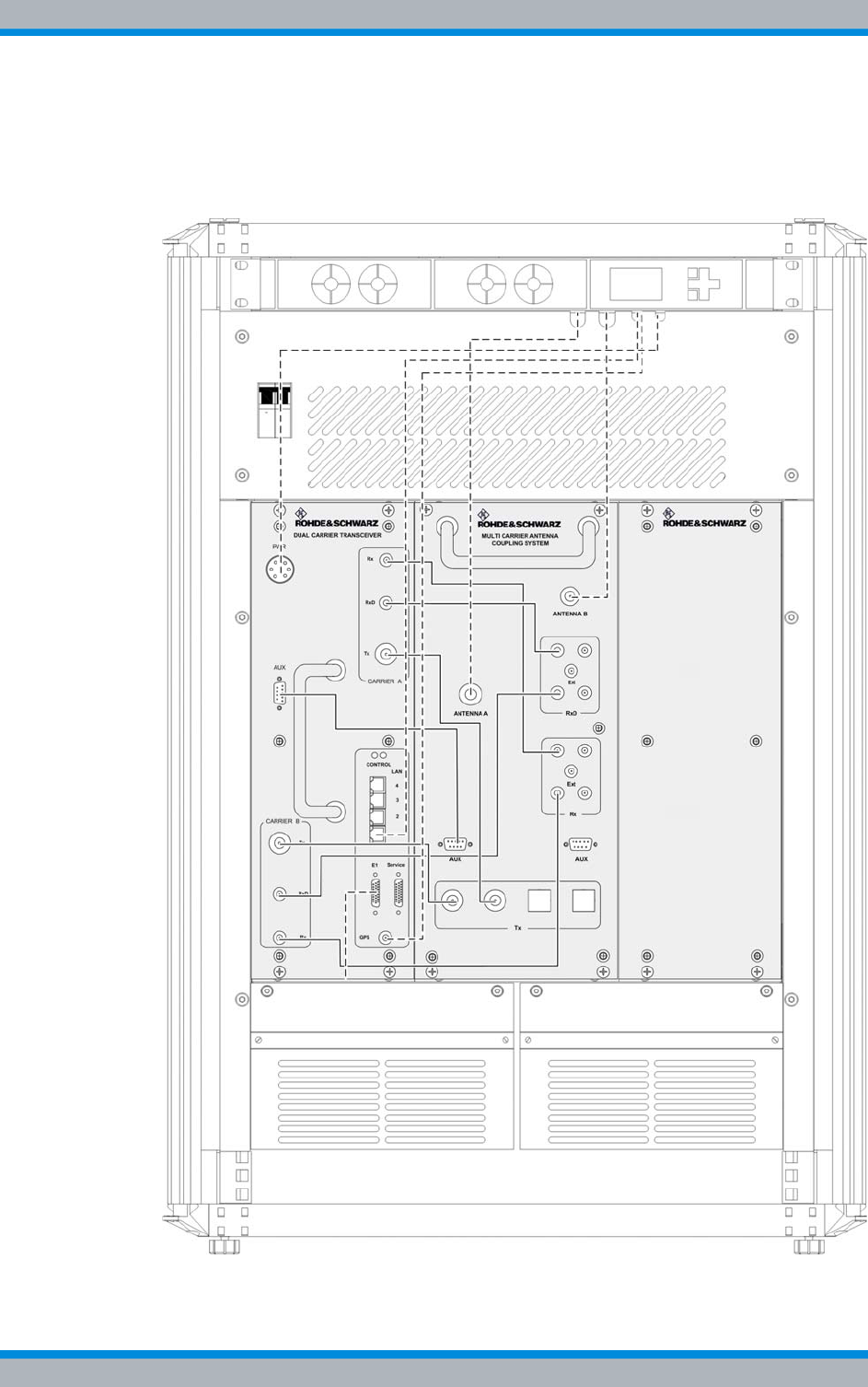
DIB-500 R4.1 Product description
Wiring diagrams
66 Installation, Operation and Service Manual 90DIB500R41IM_FCC02 – 99.1
3.3.1.1 Internal wiring of the hybrid variant – two carriers
Figure 3.24 shows the internal wiring of the DIB-500 R4.1 in the hybrid variant with two
carriers. Upon delivery, the connections have already been wired ex works.
Figure 3.24 Wiring diagram of DIB-500 R4.1 – hybrid-variant with two carriers (diversity)
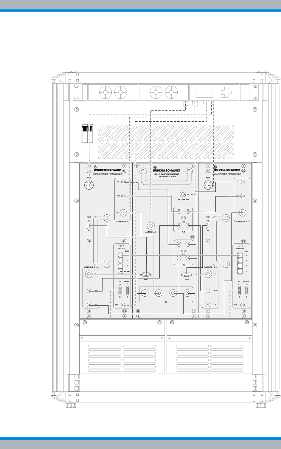
Installation, Operation and Service Manual 90DIB500R41IM_FCC02 – 99.1 67
DIB-500 R4.1 Product description
Wiring diagrams
3.3.1.2 Internal wiring of the hybrid variant – four carriers
Figure 3.25 shows the internal wiring of the DIB-500 R4.1 in the hybrid variant with four
carriers. Upon delivery, the connections have already been wired ex works.
Figure 3.25 Wiring diagram DIB-500 R4.1 – hybrid variant with four carriers (diversity)

DIB-500 R4.1 Product description
Wiring diagrams
68 Installation, Operation and Service Manual 90DIB500R41IM_FCC02 – 99.1
3.3.1.3 Hybrid variant – eight carriers
Two equipment racks installed next to each other are used for the hybrid variant as of
five carriers. The internal wiring within an equipment rack corresponds to the wiring of
the hybrid variant with four carriers, see section 3.3.1.2 on page 67.
Cable labeling for the connection of two equipment racks
For variants with more than four carriers, the corresponding connecting cables are sup-
plied. They are identified according to their intended purpose, see Table 3.31 on
page 70.
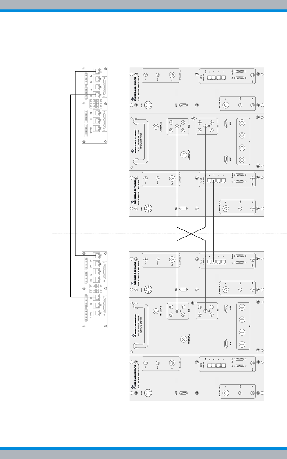
Installation, Operation and Service Manual 90DIB500R41IM_FCC02 – 99.1 69
DIB-500 R4.1 Product description
Wiring diagrams
Figure 3.26 shows the connection between the equipment racks of the DIB-500 R4.1 in
the hybrid variant with eight carriers. The connections are described in detail in the
associated table.
Figure 3.26 Wiring diagram DIB-500 R4.1 – hybrid variant with eight carriers (diversity)
2
Equipment rack A Equipment rack B
1
5
34

DIB-500 R4.1 Product description
Wiring diagrams
70 Installation, Operation and Service Manual 90DIB500R41IM_FCC02 – 99.1
3.3.1.4 Hybrid variant – Eight carriers with LRU (redundancy package)
Two equipment racks installed next to each other are used for the hybrid variant as of
five carriers. The internal wiring within an equipment rack corresponds to the wiring of
the hybrid variant with four carriers, see section 3.3.1.2 on page 67.
Table 3.31 Legend: Wiring diagram DIB-500 R4.1 – hybrid variant with eight carriers (diversity)
No. Connection from To hardware component Cable
labeling
1 E1 connection board A
(B1) E1 connection board B (A1) for connecting a
second equipment rack E1
2 E1 connection board A
(PPS) E1 connection board B (PPS) for transmitting
the PPS synchronisation clock from TIB A PPS
3 ACS A (RxD Ext) ACS B (Rx Ext) for connecting the reception
paths for diversity reception DIV
4 ACS A (Rx Ext) ACS B (RxD Ext) for connecting the reception
paths for diversity reception DIV
5 TIB B (LAN 3) TIB C (LAN 3) for connecting the TIB LAN
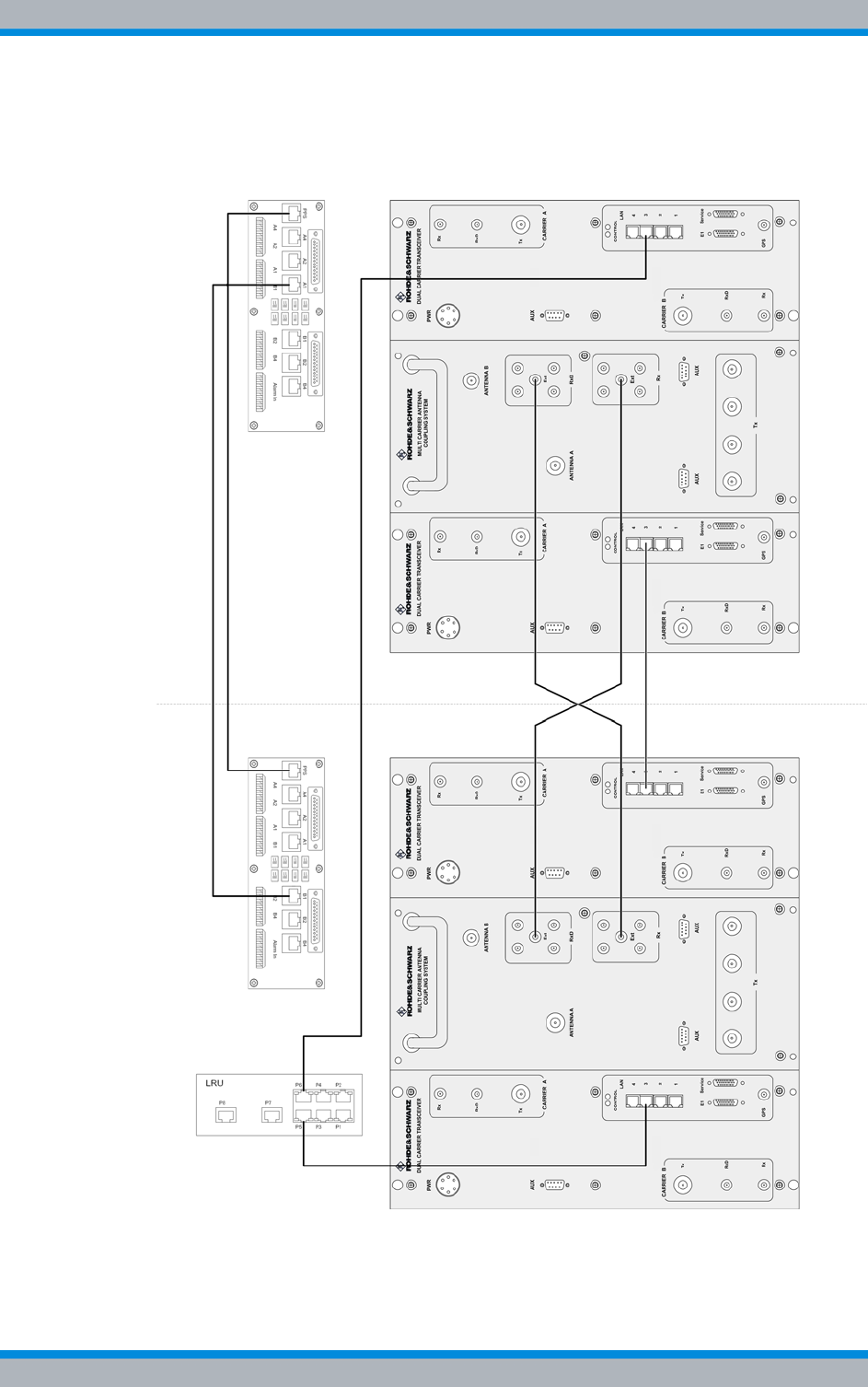
Installation, Operation and Service Manual 90DIB500R41IM_FCC02 – 99.1 71
DIB-500 R4.1 Product description
Wiring diagrams
Figure 3.27 shows the connection between the equipment racks of the DIB-500 R4.1 in
the hybrid variant with eight carriers. The connections are described in detail in the
associated table.
Figure 3.27 Wiring diagram DIB-500 R4.1 – Hybrid variant with eight carriers and redundancy package
(diversity)
1
Equipment rack A Equipment rack B
4
3
7
56
2
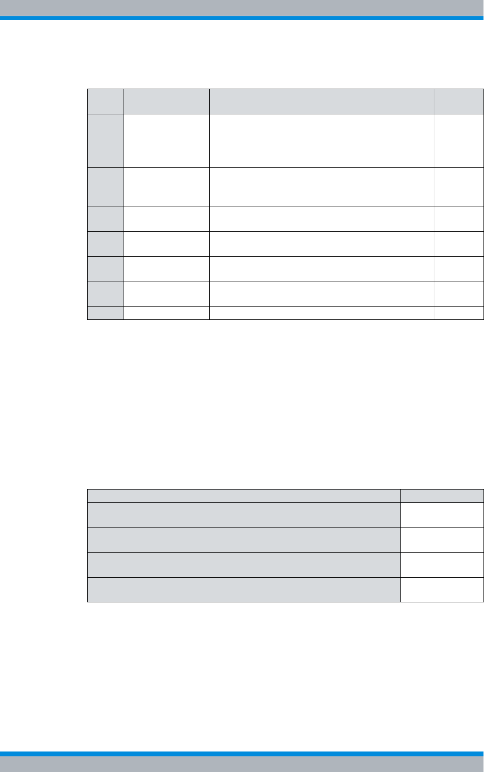
DIB-500 R4.1 Product description
Wiring diagrams
72 Installation, Operation and Service Manual 90DIB500R41IM_FCC02 – 99.1
3.3.2 Internal wiring of the cavity variant
In the cavity variant, the cavity couplers are installed in an additional cavity equipment
rack. Both equipment racks are already stacked and wired upon delivery. For the cavity
variant starting with five carriers, two equipment racks positioned next to each other are
being used which are stacked on a cavity equipment rack.
Table 3.33 provides an overview of the internal wiring diagrams of the cavity variants
that are described in the following sections.
Table 3.32 Legend: Wiring diagram DIB-500 R4.1 – Hybrid variant with eight carriers and redundancy
package (diversity)
No. Connection from To hardware component Cable
labeling
1 TIB A (LAN 3) LRU (P5) for connecting the TIB D (ring connection)
installed in a second equipment racks.
Alternatively, TIB A and TIB D can be directly con-
nected (series connection).
LAN1)
1) Ethernet cable from the redundancy package
2 LRU (P6) Connection for ring connection to:
|TIB C (LAN3) – up to six carriers
|TIB D (LAN3) – starting with seven carriers
LAN1)
3 E1 connection
board A (B1) E1 connection board B (A1) for connecting a second
equipment rack E1
4 E1 connection
board A (PPS) E1 connection board B (PPS) for transmitting the
PPS synchronisation clock from TIB A PPS
5 ACS A (RxD Ext) ACS B (Rx Ext) for connecting the reception paths
for diversity reception DIV
6 ACS A (Rx Ext) ACS B (RxD Ext) for connecting the reception paths
for diversity reception DIV
7 TIB B (LAN 3) TIB C (LAN 3) for connecting the TIB LAN
Table 3.33 Internal wiring diagrams of cavity variants
Wiring diagram Described in
Internal wiring of the cavity variant – two carriers Section 3.3.2.1
on page 73
Internal wiring of the cavity variant – four carriers Section 3.3.2.2
on page 74
Internal wiring of the cavity variant – eight carriers Section 3.3.2.3
on page 75
Wiring of cavity equipment rack Section 3.3.2.4
on page 76
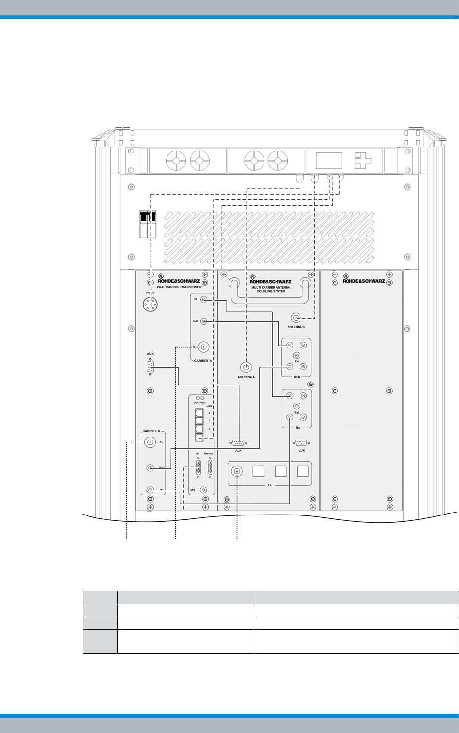
Installation, Operation and Service Manual 90DIB500R41IM_FCC02 – 99.1 73
DIB-500 R4.1 Product description
Wiring diagrams
3.3.2.1 Internal wiring of the cavity variant – two carriers
Figure 3.28 shows the wiring of the equipment rack of the DIB-500 R4.1 to the cavity
equipment rack with two carriers. The following table describes these indicators in
detail. Upon delivery, the connections have already been wired ex works.
Figure 3.28 Wiring diagram of DIB-500 R4.1 – cavity variant with two carriers (diversity)
Table 3.34 Legend: Wiring diagram DIB-500 R4.1 – cavity variant with two carriers (diversity)
No. Connection from To hardware component
1 Carrier B Tx Insulator cavity coupler B
2 Carrier A Tx Insulator cavity coupler A
3 Cavity antenna connection at
star distributor Tx input antenna A (ACS)
213
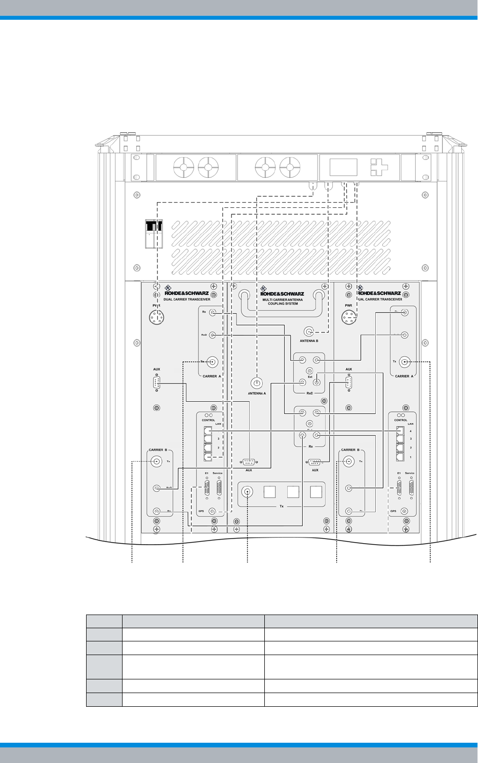
DIB-500 R4.1 Product description
Wiring diagrams
74 Installation, Operation and Service Manual 90DIB500R41IM_FCC02 – 99.1
3.3.2.2 Internal wiring of the cavity variant – four carriers
Figure 3.29 shows the wiring of the equipment rack of the DIB-500 R4.1 to the cavity
equipment rack with four carriers. The following table describes these indicators in
detail. Upon delivery, the connections have already been wired ex works.
Figure 3.29 Wiring diagram of DIB-500 R4.1 – cavity variant with four carriers (diversity)
Table 3.35 Legend: Wiring diagram DIB-500 R4.1 – cavity variant with four carriers (diversity)
No. Connection from To hardware component
1 Carrier B Tx (TIB A) Insulator cavity coupler B
2 Carrier A Tx (TIB A) Insulator cavity coupler A
3 Cavity antenna connection at
star distributor Tx input antenna A (ACS)
4 Carrier B Tx (TIB B) Insulator cavity coupler D
5 Carrier A Tx (TIB B) Insulator cavity coupler C
21345

Installation, Operation and Service Manual 90DIB500R41IM_FCC02 – 99.1 75
DIB-500 R4.1 Product description
Wiring diagrams
3.3.2.3 Internal wiring of the cavity variant – eight carriers
Two equipment cabinets installed next to each other are used for the cavity variant as of
five carriers. Apart from the wiring between the equipment cabinets A and B, the wiring
in each case corresponds to that of the cavity variant with four carriers, refer to section
3.3.2.2 on page 74.
Connection between equipment cabinets identical to hybrid variant (eight carri-
ers)
The connection between the equipment cabinets A and B is identical for the hybrid vari-
ant and cavity variant with eight carriers. The connection between the equipment cabi-
nets A and B is described with the example of the hybrid variant in section 3.3.1.3 on
page 68 or in section 3.3.1.4 on page 70.
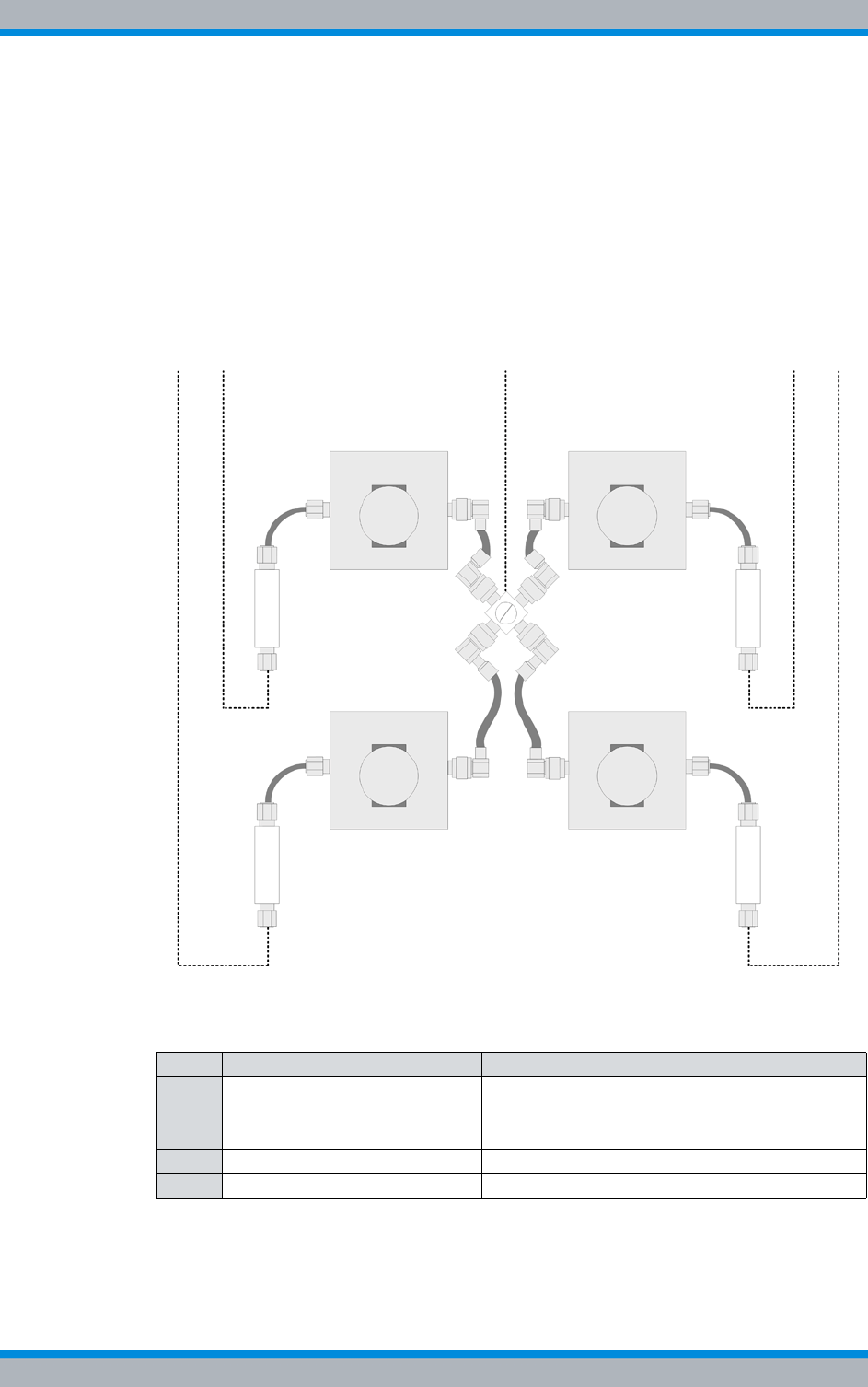
DIB-500 R4.1 Product description
Wiring diagrams
76 Installation, Operation and Service Manual 90DIB500R41IM_FCC02 – 99.1
3.3.2.4 Wiring of cavity equipment rack
The wiring between the cavity equipment rack and the equipment rack of the
DIB-500 R4.1 is identical in all variants and, for this reason, is done independently of
the installed cavity couplers and the frequency used.
Figure 3.30 shows the wiring of the cavity equipment rack to the equipment rack of the
DIB-500 R4.1 with four carriers in a schematic representation. The following table
describes these indicators in detail. Upon delivery, the connections have already been
wired ex works.
Figure 3.30 Wiring diagram of cavity equipment rack for four carriers (schematic representation)
Table 3.36 Legend: Wiring diagram of cavity equipment rack for four carriers (schematic representa-
tion)
No. Connection from To hardware component
1 Insulator cavity coupler C Carrier A Tx (TIB B)
2 Insulator cavity coupler A Carrier A Tx (TIB A)
3 Tx input antenna A (ACS) Cavity antenna connection at star distributor
4 Insulator cavity coupler B Carrier B Tx (TIB A)
5 Insulator cavity coupler D Carrier B Tx (TIB B)
12 3 45

Installation, Operation and Service Manual 90DIB500R41IM_FCC02 – 99.1 77
DIB-500 R4.1 Product description
Wiring diagrams
3.3.3 Internal wiring of the high power variant
The following sections describe the wiring diagrams of the high power variant.
Wiring of variants with two carriers
The wiring is identical for the hybrid and high power variants with two carriers.
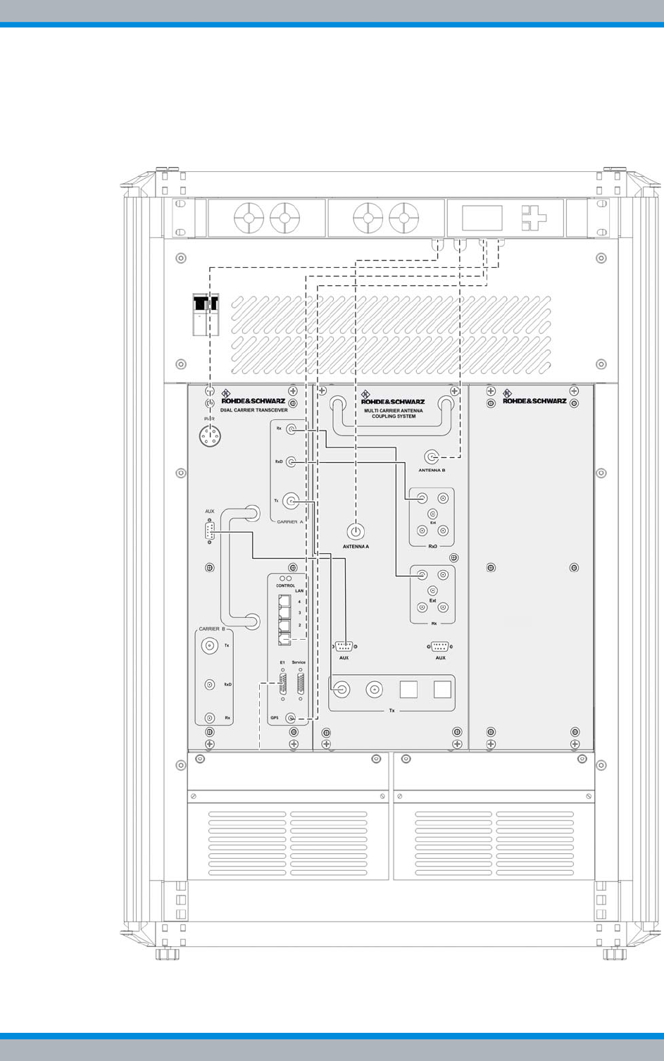
DIB-500 R4.1 Product description
Wiring diagrams
78 Installation, Operation and Service Manual 90DIB500R41IM_FCC02 – 99.1
3.3.3.1 Internal wiring of the high power variant – one carrier
Figure 3.31 shows the internal wiring of the DIB-500 R4.1 in the high power variant with
one carrier. Upon delivery, the connections have already been wired ex works.
Figure 3.31 Wiring diagram DIB-500 R4.1 – High power variant with one carrier (diversity)
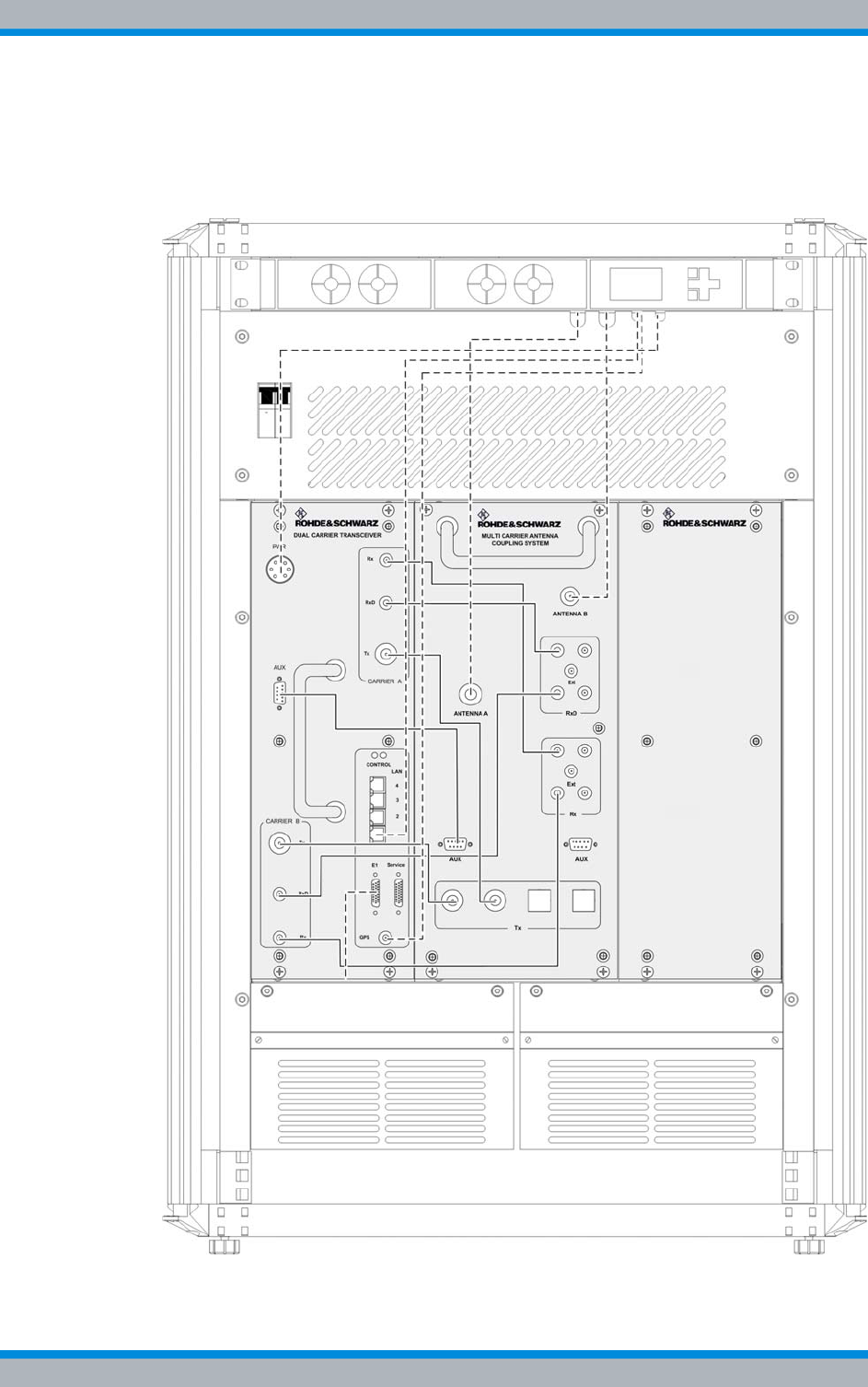
Installation, Operation and Service Manual 90DIB500R41IM_FCC02 – 99.1 79
DIB-500 R4.1 Product description
Wiring diagrams
3.3.3.2 Internal wiring of high power variant – two carriers
Figure 3.32 shows the internal wiring of the DIB-500 R4.1 in the high power variant with
two carriers. Upon delivery, the connections have already been wired ex works.
Figure 3.32 Wiring diagram of DIB-500 R4.1 – high power variant with two carriers (diversity)

DIB-500 R4.1 Product description
Wiring diagrams
80 Installation, Operation and Service Manual 90DIB500R41IM_FCC02 – 99.1
3.3.4 Internal wiring for FlexibleTx variant
The following sections contains a description of the wiring diagrams for the FlexibleTx
variant.
Wiring diagram for external antenna coupling system
The wiring diagram for the connection of external antenna coupling systems is available
in the section 5.10.2 on page 121.
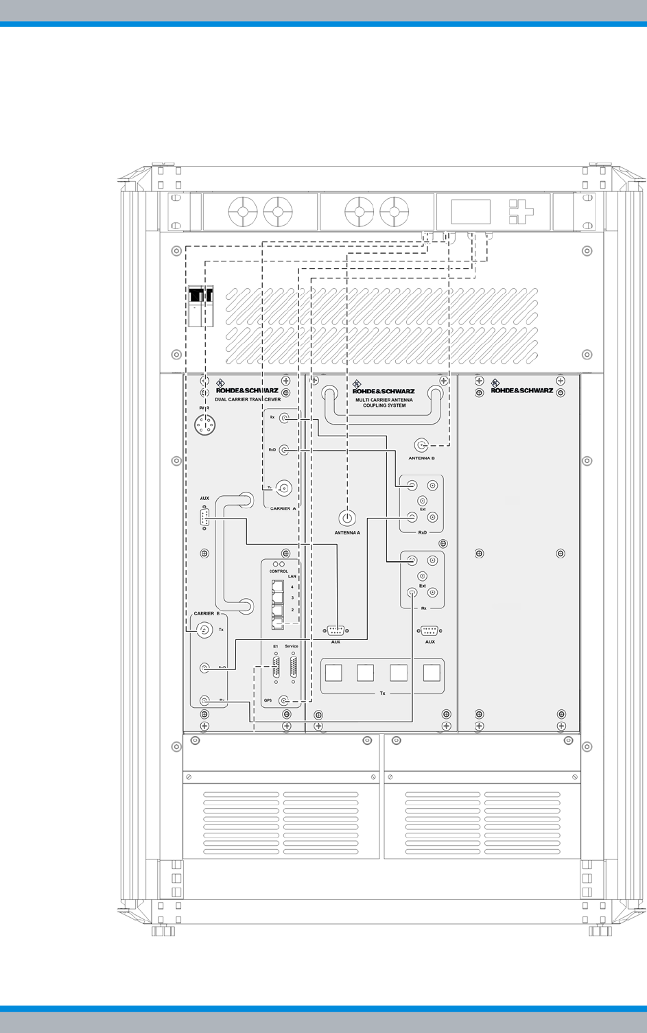
Installation, Operation and Service Manual 90DIB500R41IM_FCC02 – 99.1 81
DIB-500 R4.1 Product description
Wiring diagrams
3.3.4.1 Internal wiring of FlexibleTx variant – two carriers
Figure 3.32 shows the internal wiring of the DIB-500 R4.1 in the FlexibleTx variant with
two carriers. Upon delivery, the connections have already been wired ex works.
Figure 3.33 Wiring diagram DIB-500 R4.1 – FlexibleTx variant with two carriers (Diversity)
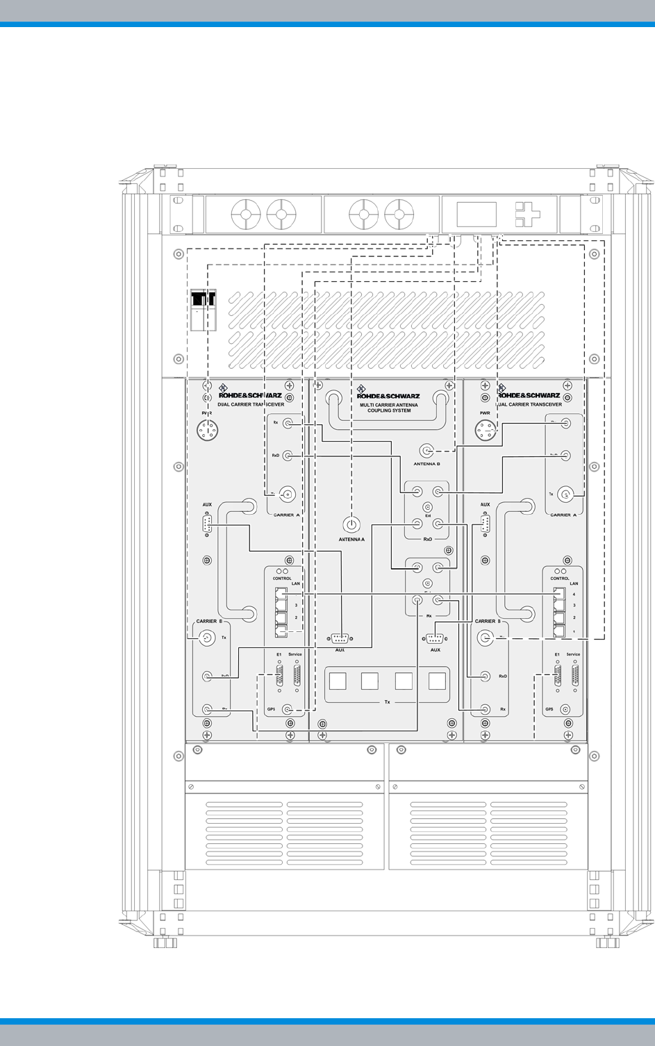
DIB-500 R4.1 Product description
Wiring diagrams
82 Installation, Operation and Service Manual 90DIB500R41IM_FCC02 – 99.1
3.3.4.2 Internal wiring for FlexibleTx variant – Four carriers
Figure 3.34 shows the internal wiring of the DIB-500 R4.1 in the FlexibleTx variant with
two carriers. Upon delivery, the connections have already been wired ex works.
Figure 3.34 Wiring diagram DIB-500 R4.1 – FlexibleTx variant with four carriers (Diversity)

Installation, Operation and Service Manual 90DIB500R41IM_FCC02 – 99.1 83
DIB-500 R4.1 Product description
Scope of delivery
3.4 Scope of delivery
The scope of delivery of the DIB-500 R4.1 depends on the respective variant. In the
Hybrid and high power variants, the base stations are delivered in a 19" equipment
racks. If there are more than four carriers, they are delivered in two 19" equipment
racks. The height of the equipment rack(s) will increase by 12 rack units each for the
cavity variants.
The variants of the DIB-500 R4.1 depend on the following characteristics:
|Voltage supply
|Antenna connection
|Number of carriers
|Frequency range
|Cavity option
|Redundancy package
Table 3.37 Scope of delivery of the DIB-500 R4.1
Designation Part number Number
Network element DIB-500 R4.1 (VDC voltage
supply),
made up of the constituents listed in section 3.1
as on page 34
5501.xxxx.xx1)
(xx depends on the selected
antenna connection, the
number of carriers and the fre-
quency range)
1
VAC voltage supply consisting of:
|Mounting frame
|SC200
|Alarm input/output module
|Rectifier module
5500.9991.00 1
Alarm system expansion1)
|Mounting frame
|SC200
|Alarm input/output module
1) already included in the VAC voltage supply by default
5500.9979.00 1
Antenna mounting kit, including the GPS
antenna 5500.8672.00 1
GPS protector (optional) 5500.3070.00 1
Expansion package for variants starting with five
carriers, consisting of connecting cables2)
2) the cable lengths refer to the standard upright versions.
5500.6186.00 1
Redundancy package3) (optional) for variants
starting with five carriers:
|LAN Routing Unit (LRU)
|Top hat rail power supply unit
|Connecting cables (Ethernet and voltage
supply)
3) Alternative to the standard expansion package
5500.6192.00 1
Rectifier module (optional) 5500.8950.00 1

DIB-500 R4.1 Product description
Scope of delivery
84 Installation, Operation and Service Manual 90DIB500R41IM_FCC02 – 99.1

Installation, Operation and Service Manual 90DIB500R41IM_FCC02 – 99.1 85
DIB-500 R4.1 Transport and storage
Safety measures and prerequisites
4 Transport and storage
This chapter describes the transport and storage of the DIB-500 R4.1 product. The
safety measures to be followed and prerequisites for the corresponding activities are
described in section 4.1 on page 85. The required tools, auxiliaries and materials are
described in section 4.2 on page 86.
4.1 Safety measures and prerequisites
The following safety measures and prerequisites must be followed for all tasks
described in this chapter:
|The safety regulations must be considered at all times, see chapter 2 on page 21.
|Observe all other activity-based safety measures and prerequisites in the activity
descriptions in this chapter.
|The transport and storage of the product must always be performed in accordance
with the regulations and temperature ranges, see Table 4.1 on page 85.
|Equipment racks may be transported only in upright position on shock-absorbing
pallets.
|Equipment racks may not be carried due to their weight. For this reason, use only
means of lifting and/or transportation, see Table 4.2 on page 86.
|If it is a single equipment rack, it may be lifted briefly by two persons to lift it onto or
from a shock-absorbing pallet.
|The transport lock installed in the condition as supplied to the customer must be
installed again before the product is transported to protect the mounting frame. The
transportation lock is fixed through the top cover of the equipment rack and is con-
tained only in variants with VAC or alarm system expansion, see section 3.1.1 on
page 34.
|The required tools, auxiliary means and materials specified must be available, refer
to section 4.2 on page 86.
Table 4.1 provides an overview of the ambient data, for which the product has been
designed. These ambient data must be taken into consideration when transporting and
storing the product.
Table 4.1 Ambient data
Operation Appropriate for ambient conditions in compliance with ETSI EN 300 019-1-3 class 3.1
Temperature range +5 °C to +45 °C
Relative humidity 5 % to 85 % (non-condensing)
Protection class(es) IP40
Transport1) Appropriate for ambient conditions in compliance with ETSI EN 300 019-1-2 class 2.2
Temperature range -40 °C to +70 °C
Storage1) Appropriate for ambient conditions in compliance with ETSI EN 300 019-1-1 class 1.2
Temperature range -40 °C to +70 °C
1) in original packaging

DIB-500 R4.1 Transport and storage
Tools, aids and materials
86 Installation, Operation and Service Manual 90DIB500R41IM_FCC02 – 99.1
4.2 Tools, aids and materials
Table 4.2 provides an overview of the tools, auxiliaries and materials required for the
steps in this chapter.
4.3 Transporting the equipment rack
This section describes the transport of the DIB-500 R4.1 product for all transports to
and from the operation room.
Use of transport devices
If a means of transportation is used, ensure that lateral tensioners or lateral safeguards
of the equipment rack connections are firmly secured during transport and cannot shift.
Loosen any tensioners and safeguards used after the transport.
The equipment rack may be transported only in upright position on shock-absorbing pal-
lets. The following procedure describes the transport on a shock-absorbing pallet with a
lift truck.
Transporting equipment racks on a pallet using a lift truck
Preparation:
✓The wall panels and the top cover of the equipment rack must be securely
installed.
✓Equipment rack doors must be locked.
✓The operation must have been shut down permanently, refer to section 8.2 on
page 164.
✓Appropriate means of transportation must be available, e.g. a lift truck.
✓The transport must be performed by at least three persons.
✓The equipment rack must be secured against overturning, e.g. with a suitable pack-
aging.
✓The equipment rack must be packaged accordingly.
✓Ensure that no slinging devices are resting on the equipment rack. They could
damage the equipment rack, e.g. by exerting pressure.
Table 4.2 Overview of tools, auxiliaries and materials (Transport and storage)
Tools, aids Materials
|Transport/lifting devices, e.g. lift truck
|In addition, at least three persons are
needed
|Coin to unscrew/tighten the mounting
screws of the equipment rack top cover
|Shock-absorbing pallet measuring at
least 70 cm x 70 cm (e.g. for transport
with a lift truck)
|Packaging material
Installation, Operation and Service Manual 90DIB500R41IM_FCC02 – 99.1 87
DIB-500 R4.1 Transport and storage
Transporting the equipment rack
Carry out the following steps:
Risk of injury
Injuries could occur due to the heavy weight of the equipment rack during lifting. In addi-
tion, it could fall down during lifting.
➔Lift the equipment rack evenly.
➔If necessary, ask an additional person to assist during lifting.
1. Lift the equipment rack evenly with two persons so that a third person can position
the pallet centered under the equipment rack.
Risk of damage
The equipment rack could be damaged while setting it down.
➔Set the equipment rack evenly onto the levelling feet.
2. Set the equipment rack evenly onto the levelling feet and centered on the pallet.
Risk of damage from tipping over
The equipment rack may tip over during transportation, resulting in damage.
➔When transporting on a lift truck ensure that the ground is suitable for transporta-
tion.
➔Avoid any vibrations due to unevenness or inclination.
➔When transporting, ensure that no lateral tilt of the equipment rack will occur.
Risk of damage due to vibrations
The equipment rack could be damaged from vibrations.
➔Always use a shock-absorbing pallet for the transport.
3. Use the means of transportation to transport the equipment rack to the intended
installation site/operating room.
4. Set the equipment rack down at the location or in the operation room.
✓You have successfully transported the equipment rack.

DIB-500 R4.1 Transport and storage
Storage
88 Installation, Operation and Service Manual 90DIB500R41IM_FCC02 – 99.1
4.4 Storage
The product must be stored in closed rooms that are dry and weatherproof. In addition,
this room must meet the required ambient conditions, refer to Table 4.1 on page 85.
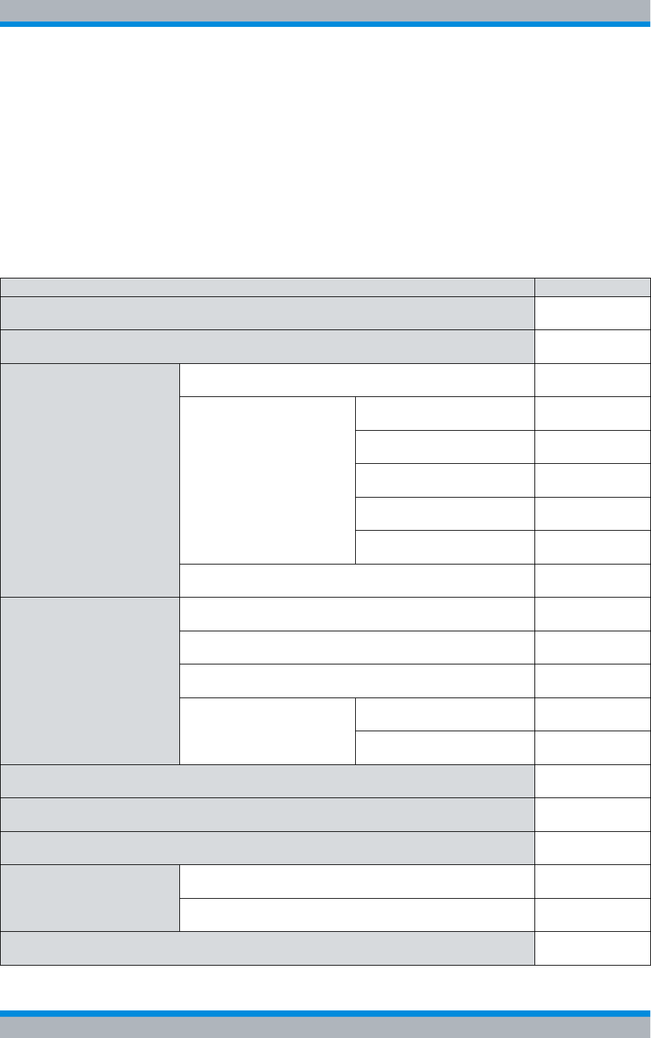
Installation, Operation and Service Manual 90DIB500R41IM_FCC02 – 99.1 89
DIB-500 R4.1 Setup and commissioning
5 Setup and commissioning
This chapter describes the setup and commissioning of the DIB-500 R4.1 product. The
safety measures to be followed and prerequisites for the corresponding tasks are
described in section 5.1 on page 90. The required tools, auxiliaries and materials are
described in section 5.2 on page 90.
The tasks listed in the following table must be performed for setting up the
DIB-500 R4.1.
Table 5.1 Overview of the tasks to be performed (Setup and commissioning)
Tasks/work steps Described in
Installing equipment racks Section 5.3 on
page 92
Removing the top cover of the mounting frame Section 5.4 on
page 94
Connecting equipment racks
(as of 5 carriers) Assembly of the redundancy package – optional Section 5.5.1 on
page 96
Installing the left top hat rail
end bracket Section 5.5.1.1
on page 97
Establishing the voltage sup-
ply of the LRU Section 5.5.1.2
on page 98
Inserting the LRU Section 5.5.1.3
on page 102
Installing the top hat rail
power supply unit Section 5.5.1.4
on page 103
Installing the right top hat rail
end bracket Section 5.5.1.5
on page 105
Connecting the equipment racks A and B Section 5.5.2 on
page 105
Connection to the electrical
system Connection with the grounding system Section 5.6.1 on
page 107
Defining the reference potential Section 5.6.2 on
page 108
Connecting the voltage supply Section 5.6.3 on
page 110
Connecting the VDC voltage
supply Section 5.6.3.1
on page 110
Connecting the VAC voltage
supply – optional Section 5.6.3.2
on page 112
Connecting Ethernet cables Section 5.7 on
page 113
Installing the GPS antenna Section 5.8 on
page 114
Installing the GPS protector - optional Section 5.9 on
page 117
Connecting antennas Connecting antennas (GPS and TETRA) Section 5.10.1 on
page 119
Connection of external antenna coupling systems – Option-
ally, only FlexibleTx variant Section 5.10.2 on
page 121
Connecting external alarm sensors (LSA+) Section 5.11 on
page 123
DIB-500 R4.1 Setup and commissioning
Safety measures and prerequisites
90 Installation, Operation and Service Manual 90DIB500R41IM_FCC02 – 99.1
5.1 Safety measures and prerequisites
For the setup and commissioning, the following safety measures and prerequisites must
be observed:
|All the supply lines/cables must be passed or suspended in a way ensuring that
– the operation of the device is not impaired,
– there are no trip hazards for the operator or any other persons,
– the required minimum distances and cable lengths are complied with.
|The site must be prepared in compliance with the document "Site Requirements".
|The DIB-500 R4.1 may be set up and commissioned only of the required ambient
conditions are met at all times, see Table 4.1 on page 85.
|The safety regulations must be considered at all times, see chapter 2 on page 21.
|Observe all other activity-based safety measures and prerequisites in the activity
descriptions in this chapter.
|The required tools and materials must be available, see section 5.2 on page 90.
5.2 Tools, aids and materials
Table 5.2 provides an overview of the tools, auxiliaries and materials required for the
steps in this chapter.
Dimensioning cable lengths
For the dimensioning of cables, consider that the equipment rack may have to be
moved for maintenance work.
Connecting external alarms –
optional, with VAC or alerting
expansion
Removing the top cover of the equipment rack Section 5.12.1 on
page 124
Connecting external alarms Section 5.12.2 on
page 126
Mounting the top cover of the mounting frame Section 5.12.3 on
page 128
Mounting the top cover of the equipment rack Section 5.13 on
page 129
Switching on the voltage source Section 5.14 on
page 129
Switching on the DIB-500 R4.1 Section 5.15 on
page 129
Table 5.1 Overview of the tasks to be performed (Setup and commissioning)
Tasks/work steps Described in

Installation, Operation and Service Manual 90DIB500R41IM_FCC02 – 99.1 91
DIB-500 R4.1 Setup and commissioning
Tools, aids and materials
Table 5.2 Overview of tools, aids and materials (setup and commissioning)
Work step Tools, aids Materials
Installing equipment racks |Transport/lifting devices, e.g. lift truck
or crane hook
|at least two persons
|suitable slinging devices (e.g. ropes,
chains or lifting straps)
|Pallet
Removing the top cover
of the mounting frame |Phillips head screwdriver size PH2
|Coin to unscrew/tighten the mounting
screws of the equipment rack top
cover
---
Assembly of the redun-
dancy package – optional |Flat-bladed screwdriver size 0.9 x5.4
|Flat-bladed screwdriver size 0.8 x2.5
|Flat-bladed screwdriver size 0.6 x4.5
|Flat-bladed screwdriver size 0.5 x3
|Redundancy package1) (optional),
consisting of
– 2 top hat rail end brackets
– 2 power supply cables
– LAN Routing Unit (LRU)
– Top hat rail power supply unit
Connecting the equip-
ment racks A and B --- |Connecting cable from the scope of
supply for variants from carriers
Connection to the electri-
cal system |M13 ring spanner
|Size 4 Allen wrench
|Flat-bladed screwdriver size 0.6 x4.5
|Cable end sleeve calliper
|Earthing cable connected with the
earthing system at the location with
eye size 13 mm according to the doc-
ument "Site Requirements"
|Power supply cable with a wire cross
section of 4 mm2 according to the
document "Site Requirements"
|Cable end sleeves
Connecting Ethernet
cables |Side cutting pliers
|Cable stripper
|Crimping tool for RJ-45 connector
|Ethernet cables according to the doc-
ument "Site Requirements"
|RJ-45 connector (unless already fas-
tened on the Ethernet cable)
|Fastening material (cable tie)
Installing the GPS protec-
tor - optional |Size 18 dynamometric key with a
torque of 100 Ncm |GPS protector (optional)
Installing the GPS
antenna |Size 4 Allen wrench
|No. 1 Phillips head screwdriver
|Size 8 dynamometric key with a
torque of 0.6 Nm
|Ladder
|GPS antennas incl. accessories from
the scope of supply, such as textile
tape2)
|Fastening material (cable tie)
Connecting antennas
(GPS and TETRA) |The required tools depend on the
antenna cable used and the related
connector.
|Antenna cable
Connecting external
alarms – optional, with
VAC or alerting expansion
|No. 1 Phillips head screwdriver |Cable tie against tensile stress
Mounting the top cover of
the equipment rack |Phillips head screwdriver size PH2
|Coin to unscrew/tighten the mounting
screws of the equipment rack top
cover
|Fastening screws previously loos-
ened
|The upper cover previously removed
together with the related grommet
1) Refer to the price list of Rohde & Schwarz Professional Mobile Radio GmbH
2) For DIB-500 R4.1 with more than two transceiver modules TIB and controller redundancy, the use of an ad-
ditional GPS antenna is recommended.
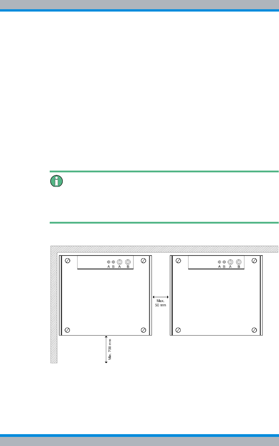
DIB-500 R4.1 Setup and commissioning
Installing equipment racks
92 Installation, Operation and Service Manual 90DIB500R41IM_FCC02 – 99.1
5.3 Installing equipment racks
Depending on the variant, the DIB-500 R4.1 consists of several equipment racks upon
delivery. Upon delivery, equipment racks have already been wired ex works.
The equipment racks may be freestanding or they may be placed against the wall with
the rear or with either side. If multiple equipment racks of the same type are used in the
operation room, these may also be positioned next to each other. It is not possible to
stack equipment racks.
The following requirements must be met for being able to operate the network element
as intended:
|Free space of at least 700 mm for service purposes:
– on the front of the equipment rack
– on the top of the equipment rack
|Maximum distance between the equipment racks (from five carriers) of 50 mm.
|The space above the equipment rack (no superstructures) depends on the bending
radius of the antenna cable used.
Required cable lengths
The cable sets for the Ethernet and E wiring refer to the standard variants. The cable
sets are designed for a max. spacing of 50 mm between the equipment racks. Longer
cables may be required for the respective application.
Figure 5.1 shows the space required when setting up the DIB-500 R4.1.
Figure 5.1 Space required for setting up the DIB-500 R4.1
Setting up the equipment rack
Preparation:
✓The site must be prepared in compliance with the document "Site Requirements".
✓The location intended for operation must have a solid and plane underground.

Installation, Operation and Service Manual 90DIB500R41IM_FCC02 – 99.1 93
DIB-500 R4.1 Setup and commissioning
Installing equipment racks
✓At least two people are required to set up the equipment rack.
✓You need suitable means of transportation, e.g. a lift truck.
✓During transport, observe the notes and procedures in chapter 4 on page 85.
✓The equipment rack must have been unpacked.
✓The equipment rack must be bolted to the pallet.
Carry out the following steps:
Risk of damage from tipping over
The equipment rack may tip over during transportation, resulting in damage.
➔When transporting on a lift truck ensure that the ground is suitable for transporta-
tion.
➔Avoid any vibrations due to unevenness or inclination.
➔When transporting, ensure that no lateral tilt of the equipment rack will occur.
1. Place the pallet with the equipment rack in the operation room.
2. Unscrew the equipment rack from the pallet and position it at the intended location
with two people.
3. Slide the two claws for floor anchorage underneath the levelling feet up to the stop
with the edges facing down.
Aligning the floor anchorage claws
Attach the floor anchorage claws diagonally (e.g. front LH side and rear RH side) to the
bottom of the equipment rack to ensure utmost protection against tilting.
4. Fasten the claws to the floor, if necessary.
5. If required, secure the equipment cabinets against tilting through additional means,
e.g. by screwing them to a wall.
6. For variants with several equipment racks, proceed as described in the previous
process steps.
✓You have successfully completed the setup.
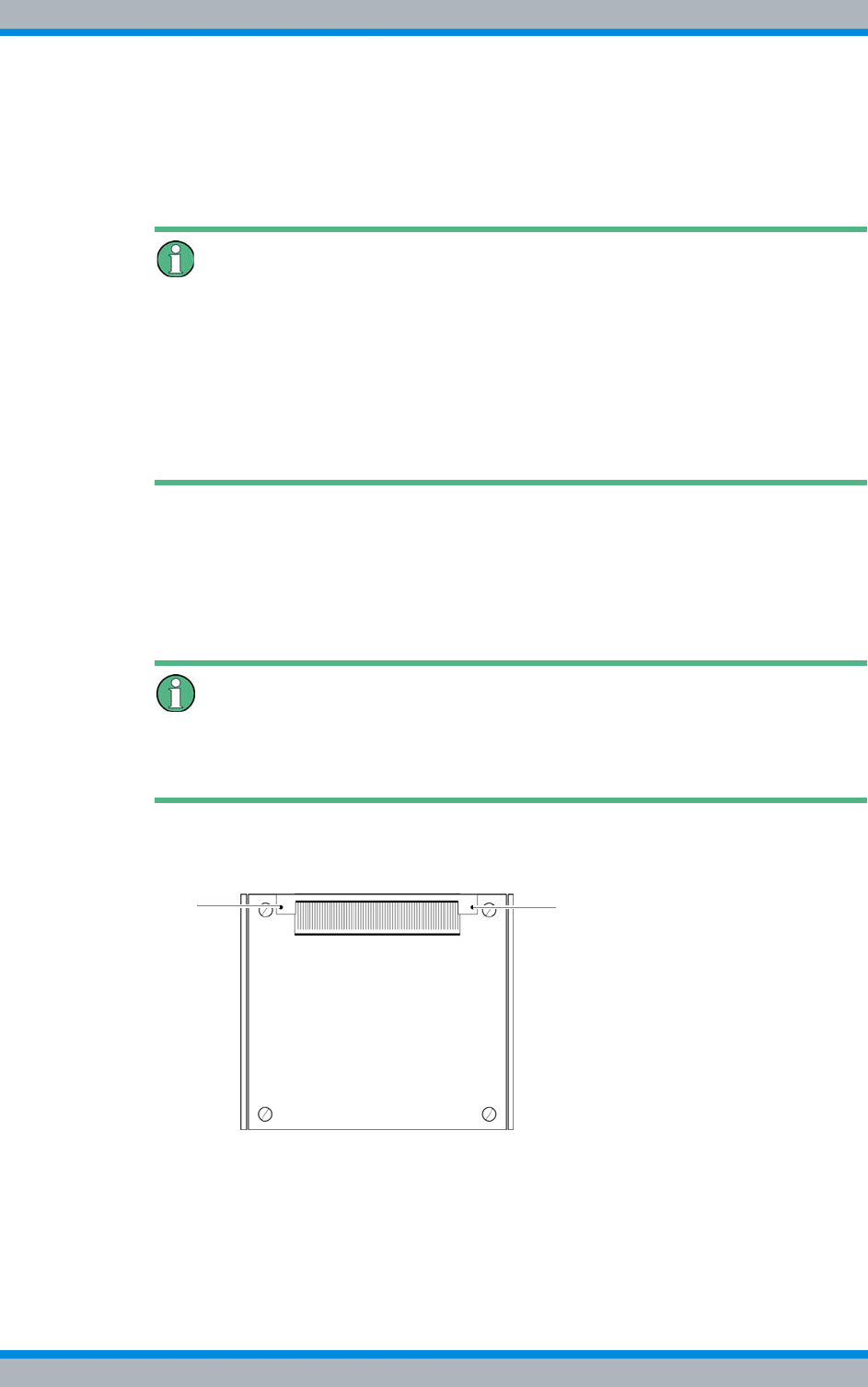
DIB-500 R4.1 Setup and commissioning
Removing the top cover of the mounting frame
94 Installation, Operation and Service Manual 90DIB500R41IM_FCC02 – 99.1
5.4 Removing the top cover of the mounting frame
To perform work in the equipment rack, the top cover of the equipment rack has to be
removed.
Removing the transportation lock – optional, only for VAC or alarm system
expansion
Upon delivery, a transportation lock is installed between the mounting frame and the
upper cover of the equipment rack, retained by the upper cover of the equipment rack.
This transportation lock must be removed prior to/while commissioning the product.
The transport lock can be removed after the upper cover of the equipment rack has
been removed. Keep the transport lock in a safe place, you may need it again for trans-
ports later on.
Proceed as follows to remove the top cover:
Preparation:
✓The tools, auxiliary means and materials specified must be available, refer to
section 5.2 on page 90.
Carry out the following steps:
Keeping materials
Keep all the materials such as fastening screws in a safe place. You will need them
again.
1. Loosen the mounting screws of the grommet using a size 2 cross-head screw-
driver, refer to Figure 5.2.
Figure 5.2 Top equipment rack cover – grommet mounting screws
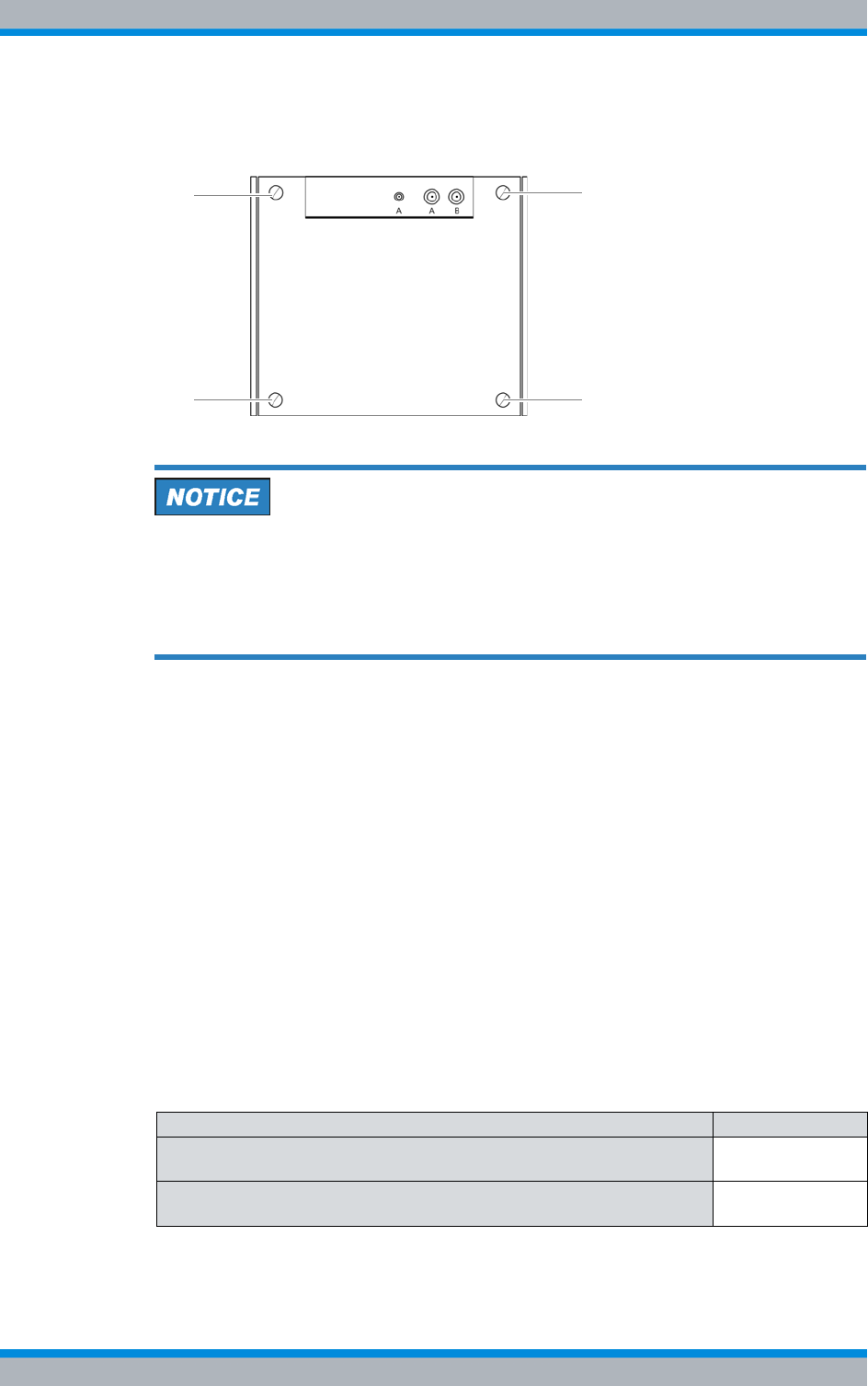
Installation, Operation and Service Manual 90DIB500R41IM_FCC02 – 99.1 95
DIB-500 R4.1 Setup and commissioning
Connecting equipment racks (as of 5 carriers)
2. Loosen the mounting screws of the equipment rack top cover using a coin, refer to
Figure 5.3.
Figure 5.3 Equipment rack top cover - mounting screws
Damage of the earthing connection
The grounding connection may be damaged if you remove the equipment rack top
cover without removing the grounding cable connected on the inside of the cover.
➔Cautiously lift the top cover of the equipment rack. When doing so, the grounding
cable must not be subject to tensile stress.
3. Loosen the grounding cable by pressing the catch of the blade connector and
pushing the blade connector out of the catch..
4. Remove the top cover of the equipment rack.
5. Remove the transportation lock, if necessary.
✓You have successfully removed the top cover.
5.5 Connecting equipment racks (as of 5 carriers)
For variants with five or more carriers (hybrid and cavity), two equipment racks are used
equipped with a total of three or four TIB transceiver modules and two antenna coupling
systems (ACS). Upon delivery, no connection exists between the equipment racks. This
connection must first be established. The procedure for connecting the two equipment
racks (A and B) is identical for the hybrid and cavity variant.
For connecting equipment racks (starting with five carriers), the tasks listed in the fol-
lowing table must be performed.
Table 5.3 Overview of the tasks to be performed (Connecting equipment racks (as of 5 carriers))
Tasks/work steps Described in
Assembly of the redundancy package – optional Section 5.5.1 on
page 96
Connecting the equipment racks A and B Section 5.5.2 on
page 105
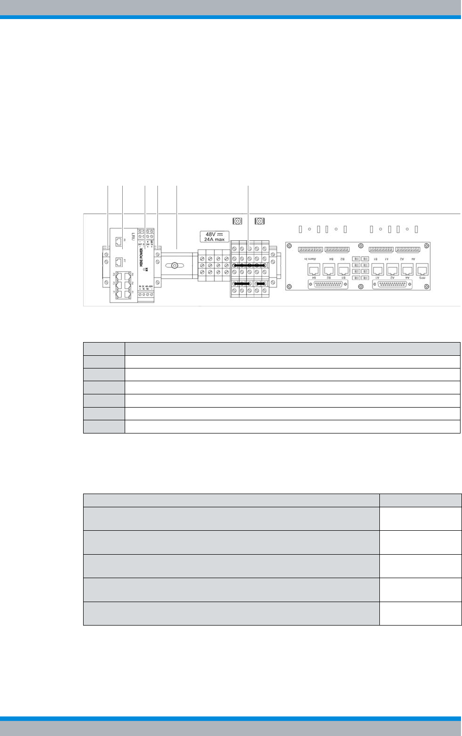
DIB-500 R4.1 Setup and commissioning
Connecting equipment racks (as of 5 carriers)
96 Installation, Operation and Service Manual 90DIB500R41IM_FCC02 – 99.1
5.5.1 Assembly of the redundancy package – optional
The redundancy package is not installed upon delivery in order to avoid transport dam-
ages. The DIB-500 R4.1 features a top hat rail so that the LRU and the corresponding
top hat rail power supply unit can be installed by snapping it in with a click mechanism
on this top hat rail in the first equipment rack (A).
Figure 5.4 shows the top hat rail of the installed components of the redundancy pack-
age. The following table describes the components in greater detail.
Figure 5.4 Redundancy package (installed)
The tasks listed in the following table must be performed for the installation of the redun-
dancy package.
Table 5.4 Legend: Redundancy package (installed)
No. Designation
1 top hat rail end bracket (left-hand side)
2LRU
3 Top hat rail power supply unit
4 top hat rail end bracket (right-hand side)
5Top hat rail
6 Terminal block
Table 5.5 Overview of the tasks to be performed (Assembly of the redundancy package – optional)
Tasks/work steps Described in
Installing the left top hat rail end bracket Section 5.5.1.1
on page 97
Establishing the voltage supply of the LRU Section 5.5.1.2
on page 98
Inserting the LRU Section 5.5.1.3
on page 102
Installing the top hat rail power supply unit Section 5.5.1.4
on page 103
Installing the right top hat rail end bracket Section 5.5.1.5
on page 105
2 31 4 5 6
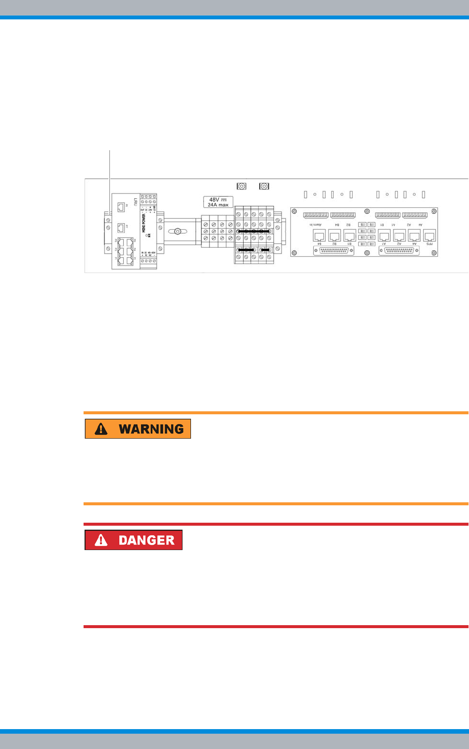
Installation, Operation and Service Manual 90DIB500R41IM_FCC02 – 99.1 97
DIB-500 R4.1 Setup and commissioning
Connecting equipment racks (as of 5 carriers)
5.5.1.1 Installing the left top hat rail end bracket
To prevent components on the top-hat rail from shifting, top-hat rail end brackets must
be installed.
Before the components are mounted on the top hat rail, a top hat rail end bracket must
be installed on the left-hand end of the top hat rail, refer to Figure 5.5.
Figure 5.5 top hat rail end bracket (left-hand side)
Proceed as follows to install top hat rail end brackets:
Preparation:
✓The tools, auxiliary means and materials specified must be available, refer to
section 5.2 on page 90.
✓The voltage source on site must be de-energised.
✓The toggle switches must be set to the "Off" position ("downward" switch position).
✓The top cover of the equipment rack must have been removed.
Carry out the following steps:
Risk of injury
The equipment rack features sharp edges on the inside. Risk of injury if you do not wear
protective gloves.
➔Always wear protective gloves for the following process steps.
Risk of electric shock
Electric shock when touching live parts. Hardware components in the equipment cabi-
net are live.
➔When performing work in the equipment cabinet, ensure that the voltage source on
site is switched off. This must have been checked with a voltmeter.
1. Clamp the top hat rail end holder onto the top hat rail in the appropriate position,
refer to Figure 5.5.
2. Tighten the screws using a flat-bladed screwdriver size 0.9 x 5.4.
✓You have successfully installed the top hat rail end bracket.
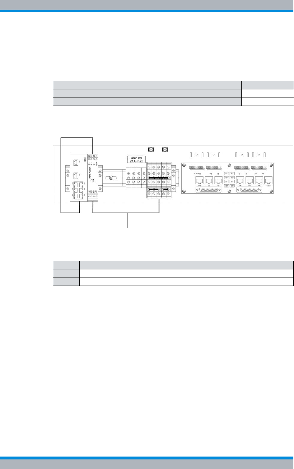
DIB-500 R4.1 Setup and commissioning
Connecting equipment racks (as of 5 carriers)
98 Installation, Operation and Service Manual 90DIB500R41IM_FCC02 – 99.1
5.5.1.2 Establishing the voltage supply of the LRU
The tasks listed in the following table must be performed for establishing the voltage
supply of the LRU.
Figure 5.6 shows an overview of the established voltage supply. The following table
describes these indicators in detail.
Figure 5.6 Overview of the voltage supply of the LRU
Table 5.6 Overview of the tasks to be performed (Establishing the voltage supply of the LRU)
Tasks/work steps Described on
Connecting the voltage supply of the top hat rail power supply unit Page99
Connecting voltage supply cables to the top hat rail power supply unit Page100
Table 5.7 Legend: Overview of the voltage supply of the LRU
No. Connection between
1 LRU and top hat rail power supply unit
2 Top hat rail power supply unit and terminals of the terminal block
1 2
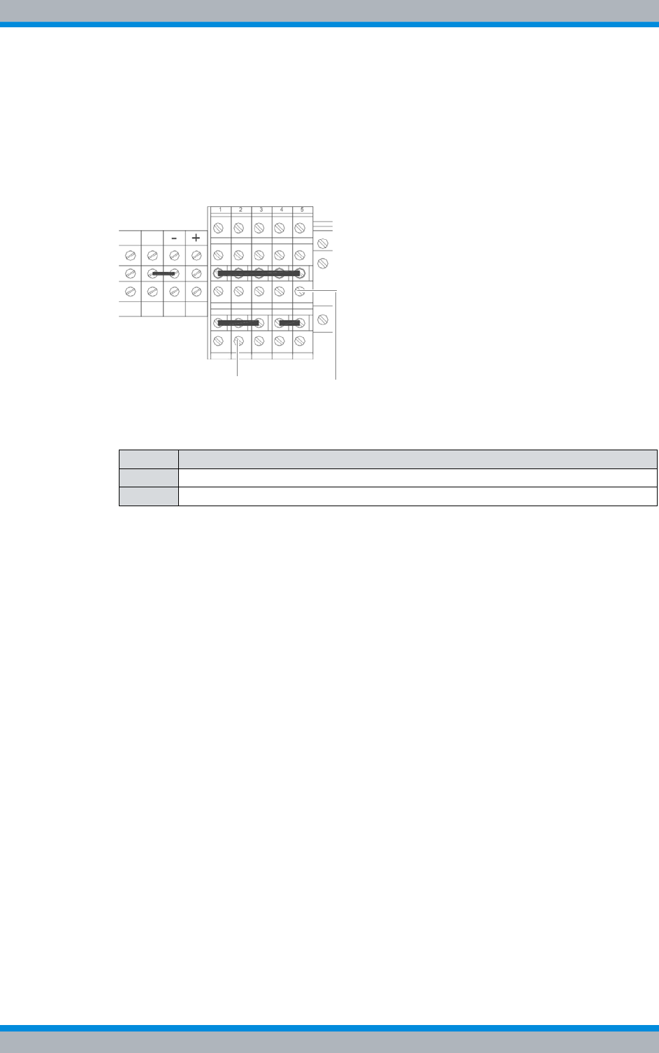
Installation, Operation and Service Manual 90DIB500R41IM_FCC02 – 99.1 99
DIB-500 R4.1 Setup and commissioning
Connecting equipment racks (as of 5 carriers)
Connecting the voltage supply of the top hat rail power supply unit
Connecting the voltage supply of the top hat rail power supply unit is done directly via
the terminal block.
Figure 5.7 shows the terminal block to which the wires of one of the power supply
cables must be connected. The following table describes these indicators in detail.
Figure 5.7 Terminals of the terminal block
Proceed as follows to connect the voltage supply cable of the top hat rail power supply
unit:
Preparation:
✓The tools, auxiliary means and materials specified must be available, refer to
section 5.2 on page 90.
✓The voltage source on site must be de-energised.
✓The toggle switches must be set to the "Off" position ("downward" switch position).
✓The top cover of the equipment rack must have been removed.
Carry out the following steps:
➔Connect the two wires of the voltage supply cable appropriately to the terminals of
the terminal block, see Figure 5.7 on page 99.
✓You have successfully connected the voltage supply cable of the top hat rail power
supply unit.
Table 5.8 Legend: Terminals of the terminal block
No. Wire colour
1white
2brown
2
1
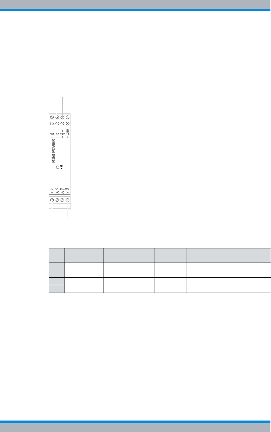
DIB-500 R4.1 Setup and commissioning
Connecting equipment racks (as of 5 carriers)
100 Installation, Operation and Service Manual 90DIB500R41IM_FCC02 – 99.1
Connecting voltage supply cables to the top hat rail power supply unit
The voltage supply cables must be connected to the top hat rail power supply unit
before the power supply unit is installed.
Figure 5.8 shows the terminals of the top hat rail power supply unit to which the power
supply cables must be connected. The following table describes these indicators in
detail.
Figure 5.8 Connectors for the voltage supply cable on the top hat rail power supply unit
Proceed as follows to connect the voltage supply cable to the top hat rail power supply
unit:
Preparation:
✓The tools, auxiliary means and materials specified must be available, refer to
section 5.2 on page 90.
✓The voltage source on site must be de-energised.
✓The toggle switches must be set to the "Off" position ("downward" switch position).
✓The top cover of the equipment rack must have been removed.
✓The power supply cable of the top hat rail power supply unit must have been con-
nected to the terminals of the terminal block.
Table 5.9 Legend: Connectors for the voltage supply cable on the top hat rail power supply unit
No. Designation Input/output Wire col-
our Connection between
1 - (DC) Output: 24 VDC white LRU and top hat rail power supply
unit
2 + (1A) brown
3 - Input: 48 VDC white top hat rail power supply unit and
voltage supply connector
4 + brown
4
2
3
1
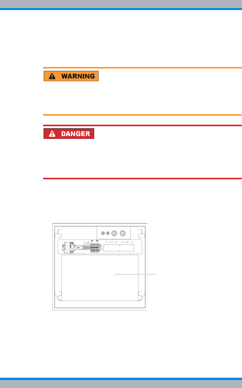
Installation, Operation and Service Manual 90DIB500R41IM_FCC02 – 99.1 101
DIB-500 R4.1 Setup and commissioning
Connecting equipment racks (as of 5 carriers)
Carry out the following steps:
1. Connect the voltage supply cable for the connection between the LRU and the top
hat rail power supply unit with the corresponding terminals of the top hat rail power
supply unit, refer to Figure 5.8 on page 100. Use a size 0.8 x 2.5 flat-bladed screw-
driver for this purpose.
Risk of injury
The equipment rack features sharp edges on the inside. Risk of injury if you do not wear
protective gloves.
➔Always wear protective gloves for the following process steps.
Risk of electric shock
Electric shock when touching live parts. Hardware components in the equipment cabi-
net are live.
➔When performing work in the equipment cabinet, ensure that the voltage source on
site is switched off. This must have been checked with a voltmeter.
2. Connect the voltage supply cable for the connection between the top hat rail power
supply unit and the voltage supply connector to the appropriate terminals of the top
hat rail power supply unit, refer to Figure 5.8 on page 100. Use a size 0.8 x 2.5 flat-
bladed screwdriver for this purpose.
3. Place the top hat rail power supply unit onto the upper side of the mounting frame.
Figure 5.9 Upper side of the mounting frame
✓You have successfully connected voltage supply cables to the top hat rail power
supply unit.
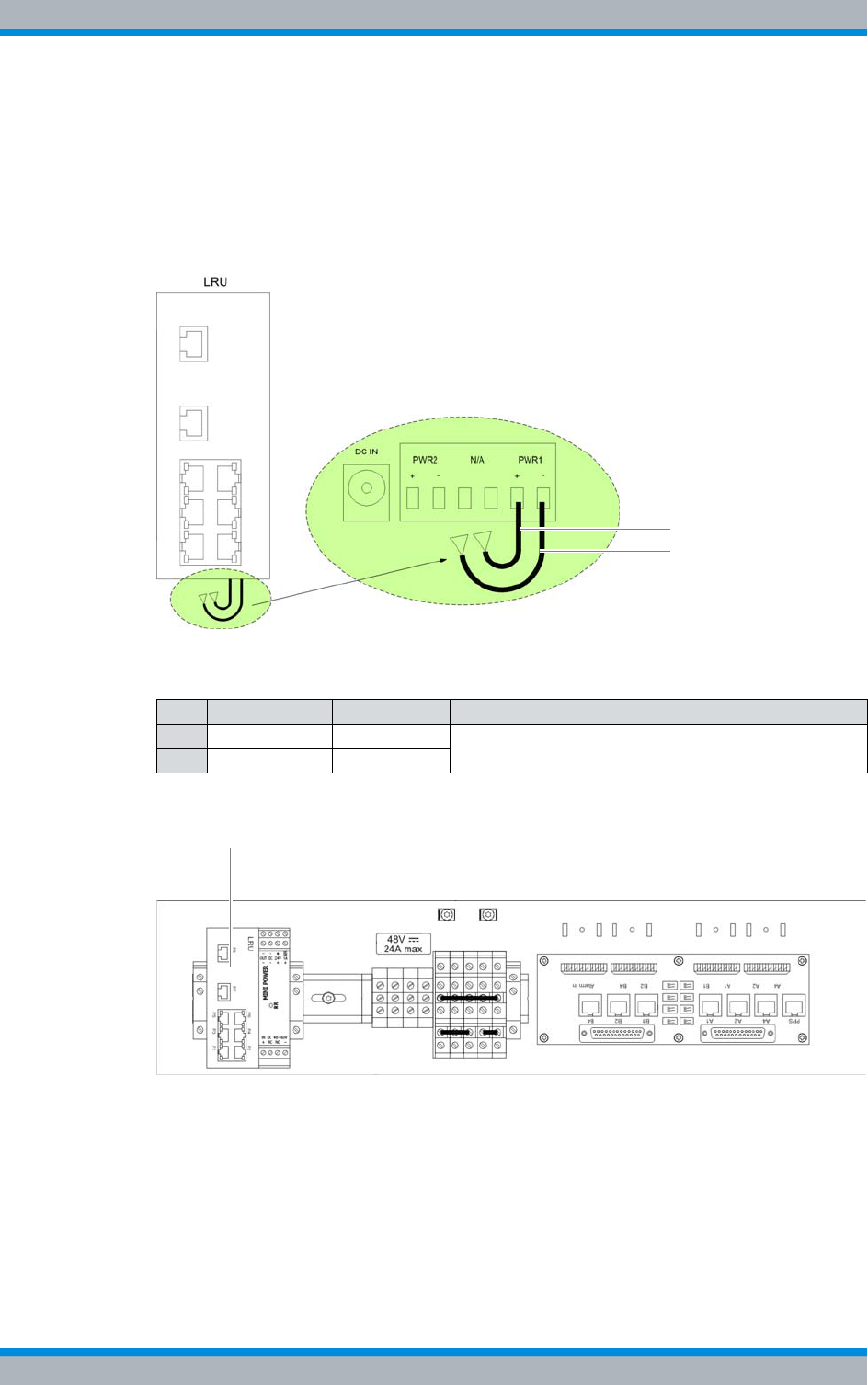
DIB-500 R4.1 Setup and commissioning
Connecting equipment racks (as of 5 carriers)
102 Installation, Operation and Service Manual 90DIB500R41IM_FCC02 – 99.1
5.5.1.3 Inserting the LRU
The LRU must be connected to the top hat rail. First, the power supply cable to the top
hat rail power supply unit must be connected.
Figure 5.10 shows the voltage supply connection of the LRU. The following table
describes it in detail.
Figure 5.10 Voltage supply connection of the LRU
Figure 5.11 shows the position of the LRU on the top hat rail .
Figure 5.11 LRU on the top hat rail
Inserting the LRU
Preparation:
✓The voltage source on site must be de-energised.
✓The toggle switches must be set to the "Off" position ("downward" switch position).
✓The top cover of the equipment rack must have been removed.
✓The power supply cables must have been connected to the top hat rail power sup-
ply unit.
Table 5.10 Legend: Voltage supply connection of the LRU
No. Designation Wire colour Connection between
1 PWR1 + brown LRU and top hat rail power supply unit
2 PWR2 - white
1
2
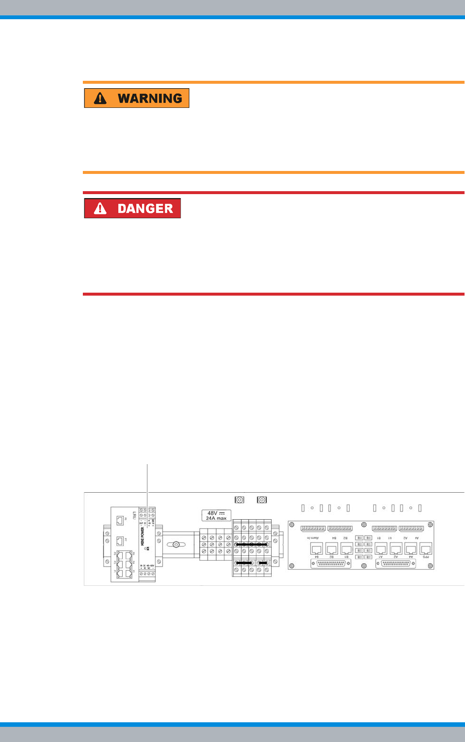
Installation, Operation and Service Manual 90DIB500R41IM_FCC02 – 99.1 103
DIB-500 R4.1 Setup and commissioning
Connecting equipment racks (as of 5 carriers)
Carry out the following steps:
Risk of injury
The equipment rack features sharp edges on the inside. Risk of injury if you do not wear
protective gloves.
➔Always wear protective gloves for the following process steps.
Risk of electric shock
Electric shock when touching live parts. Hardware components in the equipment cabi-
net are live.
➔When performing work in the equipment cabinet, ensure that the voltage source on
site is switched off. This must have been checked with a voltmeter.
1. Connect the voltage supply cable to the LRU according to the labeling, refer to Fig-
ure 5.10 on page 102.
2. Plug the LRU onto the top hat rail from above, refer to Figure 5.11 on page 102.
The catch must snap in audibly.
✓The installation of the LRU has thus been completed.
5.5.1.4 Installing the top hat rail power supply unit
The top hat rail power supply unit must be connected to the top hat rail.
Figure 5.12 shows the position of the top hat rail power supply unit on the top hat rail.
Figure 5.12 Top hat rail power supply unit on the top hat rail
Proceed as follows to install the top hat rail power supply unit:
Preparation:
✓The voltage source on site must be de-energised.
✓The toggle switches must be set to the "Off" position ("downward" switch position).
✓The top cover of the equipment rack must have been removed.
DIB-500 R4.1 Setup and commissioning
Connecting equipment racks (as of 5 carriers)
104 Installation, Operation and Service Manual 90DIB500R41IM_FCC02 – 99.1
✓The power supply cables must have been connected to the top hat rail power sup-
ply unit.
✓The LRU must be installed.
Carry out the following steps:
Risk of damage
The connected wires of the voltage supply cables connected to the top hat rail power
supply unit may be torn out of the terminals.
➔Proceed with caution when installing the top hat rail power supply unit.
➔Ensure that the voltage supply cables do not get caught on any projecting parts dur-
ing installation.
Risk of injury
The equipment rack features sharp edges on the inside. Risk of injury if you do not wear
protective gloves.
➔Always wear protective gloves for the following process steps.
Risk of electric shock
Electric shock when touching live parts. Hardware components in the equipment cabi-
net are live.
➔When performing work in the equipment cabinet, ensure that the voltage source on
site is switched off. This must have been checked with a voltmeter.
➔Plug the top hat rail power supply unit onto the top hat rail from above, refer to Fig-
ure 5.12 on page 103. The catch must snap in audibly.
✓You have successfully installed the top hat rail power supply unit.
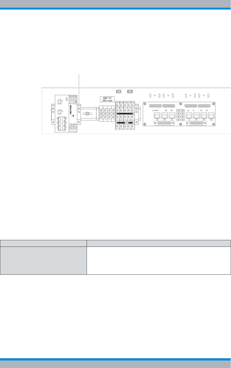
Installation, Operation and Service Manual 90DIB500R41IM_FCC02 – 99.1 105
DIB-500 R4.1 Setup and commissioning
Connecting equipment racks (as of 5 carriers)
5.5.1.5 Installing the right top hat rail end bracket
To prevent components on the top-hat rail from shifting, top-hat rail end brackets must
be installed.
To secure the components reliably, a top hat rail end bracket must be installed to the
right of the top hat rail power supply unit, refer to Figure 5.13.
Figure 5.13 top hat rail end bracket (right-hand side)
The following conditions must be met to install the right-hand top hat rail end bracket:
|The LRU must be installed.
|The top hat rail power supply unit must have been installed.
The procedure for installing top hat rail end brackets is described in section 5.5.1.1 on
page 97.
5.5.2 Connecting the equipment racks A and B
To be able to operate variants with more than four carriers (hybrid and cavity), the two
equipment racks (A and B) must be connected with each other on site.
Table 5.11 describes the connections that must be made when connecting the equip-
ment racks.
Table 5.11 Connecting equipment racks – required connections
Connection Description
TIB transceiver modules (cabinet A and
B) – via the E1 connection board The TIB transceiver modules are connected with each other in a chain
via the E1 connection board. The connection is made via the corre-
sponding connectors on the E1 connection board so that the first TIB
transceiver module is connected with the second one, the second one
with the third one, etc.

DIB-500 R4.1 Setup and commissioning
Connecting equipment racks (as of 5 carriers)
106 Installation, Operation and Service Manual 90DIB500R41IM_FCC02 – 99.1
Connecting the equipment racks
Preparation:
✓The two equipment racks must already be installed in the location provided for this
purpose, refer to section 5.3 on page 92.
✓The redundancy package must have been installed in equipment rack A (optional),
see section 5.5.1 on page 96.
Carry out the following steps:
Wiring diagrams for connecting the equipment racks A and B
The required wiring diagrams are described in the following sections:
|Without redundancy package, see section 3.3.1.3 on page 68,
|With redundancy package, see section 3.3.1.4 on page 70.
➔Connect the cables from the scope of supply with the corresponding connections
between the two equipment racks.
✓The equipment racks have thus been connected with each other.
TIB transceiver
modules (cabinet A
and B) – via Ether-
net
via TIB The TIB transceiver modules are chained via Ethernet. The connection
is made from the first to the second and from the second to the third TIB
transceiver module, etc.
via TIB and LRU
(optional, redun-
dancy package)
The TIB transceiver modules are connected with each other via Ether-
net in the "shape of a ring," see section 3.1.3 on page 42.
GPS synchronisation – via PPS Each TIB transceiver module is equipped with a GPS receiver for this
purpose. For operating both the equipment racks on one GPS antenna
only (mounted to equipment rack A), a PPS (Pulse per Second) con-
nection has been provided. The two equipment racks are connected
with each other through the PPS port on the respective E1 connection
boards.
The PPS signals from TIB transceiver module A and B within an equip-
ment rack are connected with each other and to the E1 connection
board.
Rx antennas (with diversity) If diversity reception is required, the corresponding connectors of the
two equipment racks must be connected with each other.
Table 5.11 Connecting equipment racks – required connections
Connection Description
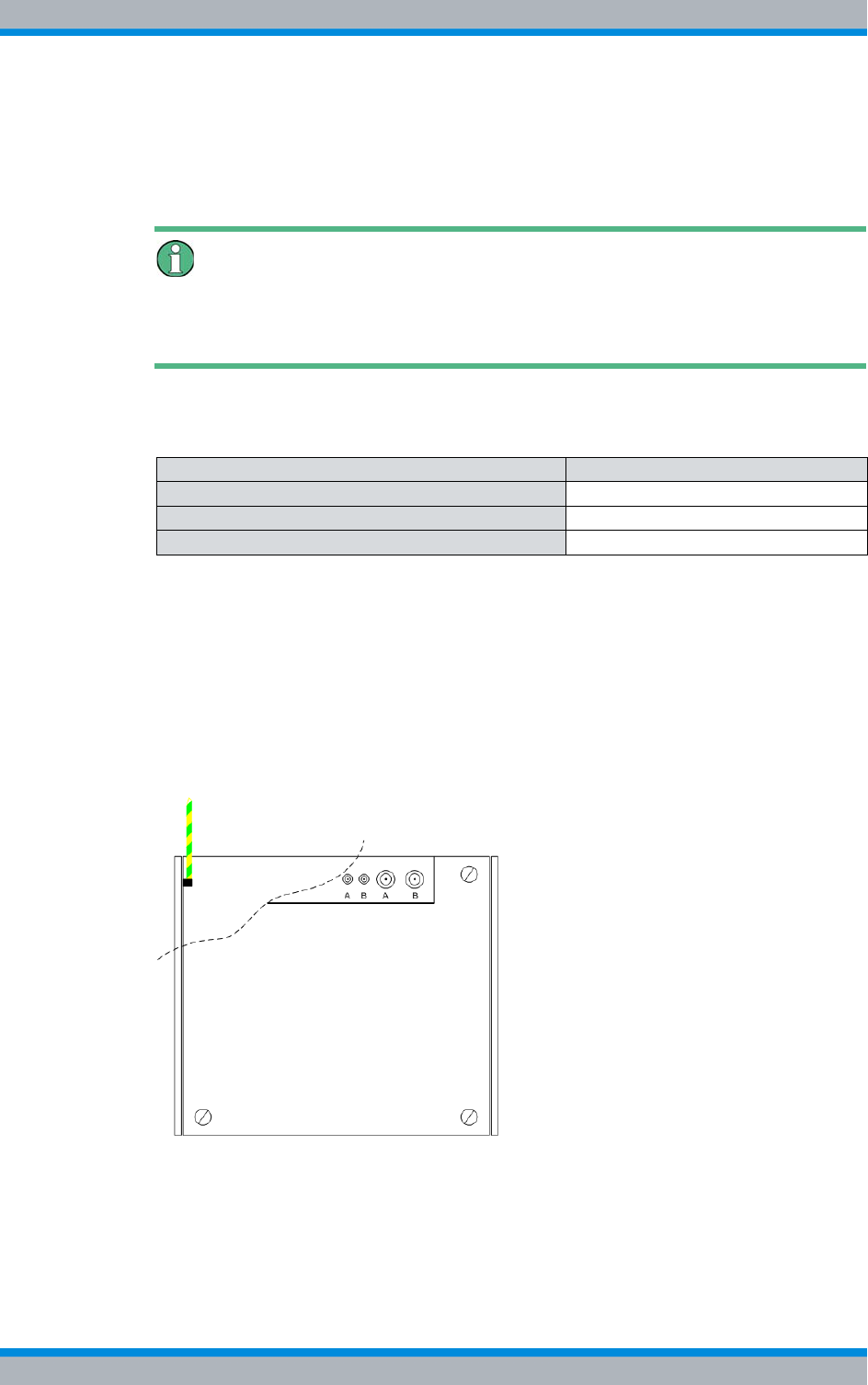
Installation, Operation and Service Manual 90DIB500R41IM_FCC02 – 99.1 107
DIB-500 R4.1 Setup and commissioning
Connection to the electrical system
5.6 Connection to the electrical system
The following section describes the procedure for performing the electrical connection
of the product properly.
Defining the reference potential
For the electrical connection of the DIB-500 R4.1, it is necessary to define the reference
potential and connect an earthing cable accordingly, see section 5.6.2 on page 108.
The tasks listed in the following table must be performed for the electrical connection.
5.6.1 Connection with the grounding system
Before you can connect and switch on the voltage supply, the equipment rack must be
connected with the earthing system at the location.
For connection with the grounding system, a grounding connector for the grounding
cable (green-yellow) has been provided below the top cover of the equipment cabinet.
Figure 5.14 shows the position of the grounding connector in the equipment rack.
Figure 5.14 Equipment rack grounding connector
Proceed as follows to connect the equipment rack to the grounding system:
Preparation:
✓An appropriate grounding system (earth circuit connector, etc.) must already be
installed.
Table 5.12 Overview of the tasks to be performed (Connection to the electrical system)
Tasks/work steps Described in
Connection with the grounding system Section 5.6.1 on page 99
Defining the reference potential Section 5.6.2 on page 108
Connecting the voltage supply Section 5.6.3 on page 110

DIB-500 R4.1 Setup and commissioning
Connection to the electrical system
108 Installation, Operation and Service Manual 90DIB500R41IM_FCC02 – 99.1
✓You need a green-yellow earthing cable that is already connected to the earthing
system.
✓The equipment rack must be accessible from above.
✓The upper cover of the equipment rack must have been removed, refer to
section 5.4 on page 94.
Carry out the following steps:
1. Loosen the outer nut of the earth connection on the equipment rack using the 13-
mm ring spanner.
2. Remove the spring washer and the plain washer.
Cable damage
If cables are routed over sharp edges or in bending radiuses too small for the cables,
the cables may be damaged.
➔Never route cables over sharp edges and always maintain to the bending radius.
3. Slide the eye of the grounding cable onto the threaded bolt of the grounding con-
nector.
4. Slide the washer and then the spring washer onto the threaded pin of the ground-
ing connector.
5. Retighten the outer nut of the earth connection using the 13-mm ring spanner.
✓The equipment rack is connected to the grounding system.
5.6.2 Defining the reference potential
The reference potential must be defined at the terminal block of the DIB-500 R4.1
depending on the earthing (reference potential) on site (negative terminal earthing or
positive terminal earthing). To do so, you have to connect an earthing cable preinstalled
at the terminal block corresponding to the reference potential at the location to a spe-
cific terminal of the terminal block.
The reference potential must be defined for VDC as well as VAC voltage supply.
Defining the reference potential
Preparation:
✓The voltage source on site must be switched off.
✓The equipment rack must be connected to the grounding system.
✓The toggle switches must be set to the "Off" position ("downward" switch position).
✓The site must be prepared in compliance with the document "Site Requirements".
✓The top cover of the equipment rack must have been removed.
✓The reference potential on site must be known.
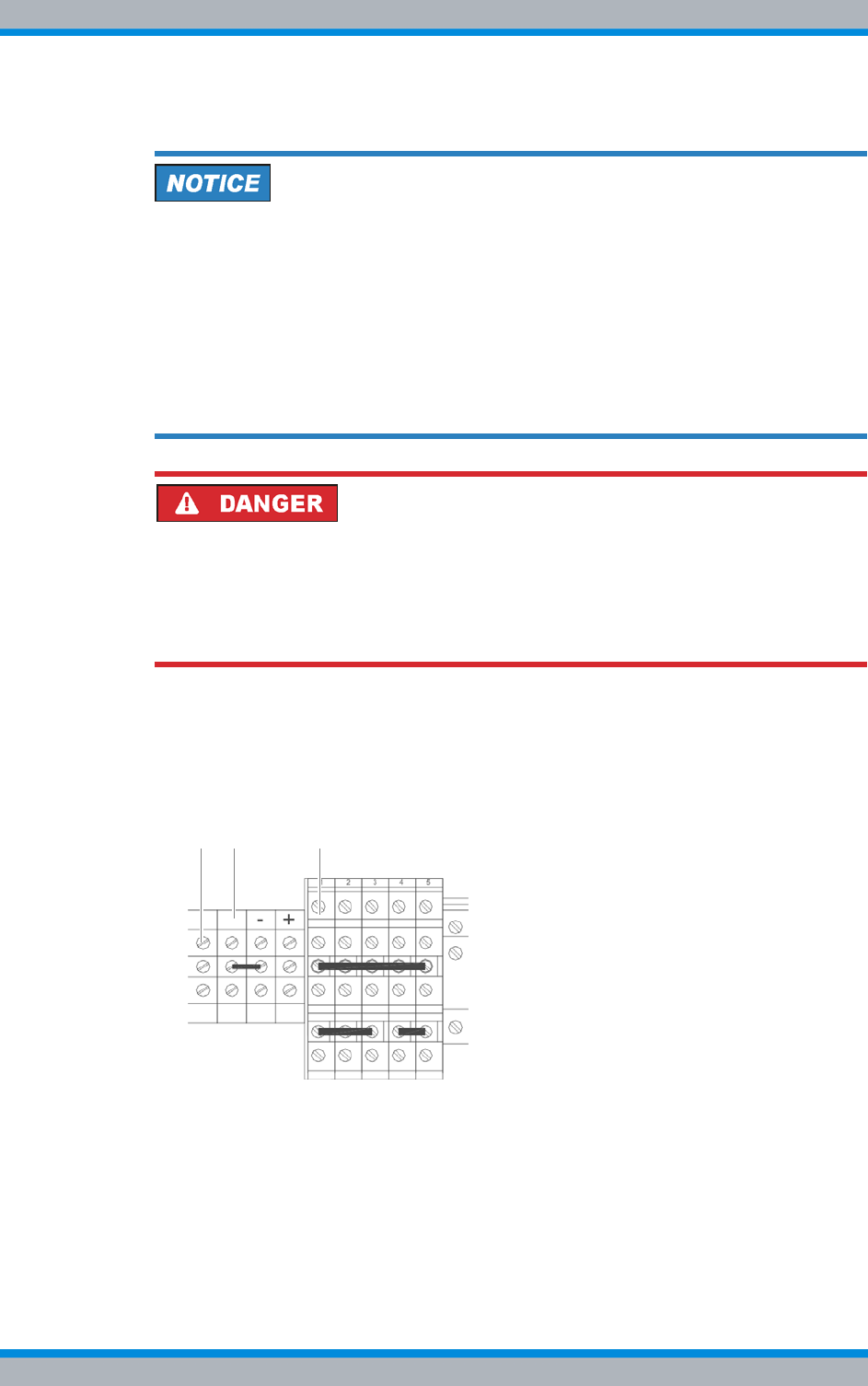
Installation, Operation and Service Manual 90DIB500R41IM_FCC02 – 99.1 109
DIB-500 R4.1 Setup and commissioning
Connection to the electrical system
Carry out the following steps:
Risk of short circuit.
The product may be damaged if the live wires of the voltage supply cable are connected
without grounding. In addition, an incorrectly connected earthing cable can cause a
short circuit, e.g. if the voltage source requires grounding on the positive terminal, the
earthing cable, however, is connected to the terminal marked with "-".
➔As an overvoltage protection and lightning arrester, it is mandatory that one terminal
of the supply circuit be earthed.
➔Connect the preinstalled earthing cable corresponding to the earthing at the location
as described below.
Risk of electric shock
Electric shock when touching live parts. Hardware components in the equipment cabi-
net are live.
➔When performing work in the equipment cabinet, ensure that the voltage source on
site is switched off. This must have been checked with a voltmeter.
➔Connect the preinstalled yellow-green grounding cable (1) according to the earth-
ing at the location
➔in the case of positive terminal earthing with the terminal identified by "+" (3), or
➔in the case of a negative terminal earthing with the terminal identified by "-" (2), see
Figure 5.15.
Figure 5.15 Terminals for defining the reference potential
✓You have successfully defined the reference potential.
1 2 3
DIB-500 R4.1 Setup and commissioning
Connection to the electrical system
110 Installation, Operation and Service Manual 90DIB500R41IM_FCC02 – 99.1
5.6.3 Connecting the voltage supply
The procedure for connecting the voltage supply cable differs depending on the type of
voltage supply (VDC, optional VAC).
Risk of damage
Connecting VAC and VDC power supply cables at the same time can damage the
DIB-500 R4.1.
➔Never connect the VAC and VDC voltage supply cables at the same time.
➔The connection must be made by an electrician.
The procedures for connecting the VDC and VAC voltage supply are described in the fol-
lowing sections.
5.6.3.1 Connecting the VDC voltage supply
In the case of a DIB-500 R4.1 with VDC voltage supply, the voltage supply is connected
directly via the corresponding terminals of the terminal block, see 3.1.5 on page 45.
Clamp specification
The terminals are dimensioned for cable cross sections of up to 4 mm2.
Proceed as follows to connect the voltage supply cable:
Preparation:
✓The voltage source on site must be switched off.
✓The equipment rack must be connected to the grounding system.
✓The toggle switches must be set to the "Off" position ("downward" switch position).
✓The site must be prepared in compliance with the document "Site Requirements".
✓The top cover of the equipment rack must have been removed.
✓The reference potential must have been defined.
Carry out the following steps:
Cable damage
If cables are routed over sharp edges or in bending radiuses too small for the cables,
the cables may be damaged.
➔Never route cables over sharp edges and always maintain to the bending radius.
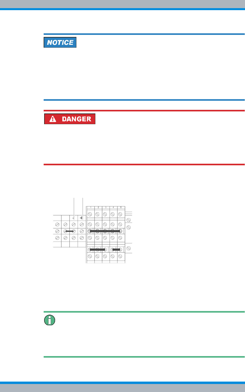
Installation, Operation and Service Manual 90DIB500R41IM_FCC02 – 99.1 111
DIB-500 R4.1 Setup and commissioning
Connection to the electrical system
Risk of short circuit.
The product may be damaged if the live wires of the voltage supply cable are connected
without grounding. In addition, an incorrectly connected earthing cable can cause a
short circuit, e.g. if the voltage source requires grounding on the positive terminal, the
earthing cable, however, is connected to the terminal marked with "-".
➔Ensure that the reference potential has already been defined or that this process
step is performed first, see section 5.6.2 on page 108.
Risk of electric shock
Electric shock when touching live parts. Hardware components in the equipment cabi-
net are live.
➔When performing work in the equipment cabinet, ensure that the voltage source on
site is switched off. This must have been checked with a voltmeter.
1. Connect the positive voltage supply cable with the terminal (2) identified by "+",
refer to Figure 5.16.
Figure 5.16 Voltage supply connector
2. Connect the negative voltage supply cable with the terminal (1) identified by "-",
refer to Figure 5.16.
✓You have successfully connected the power supply cables.
Switching on the Voltage Source Later on
Since the commissioning of the network requires additional work steps that need to be
performed in the equipment rack, the voltage source must stay switched off for the time
being. Switching on the voltage source is required only later on for the configuration.
1 2
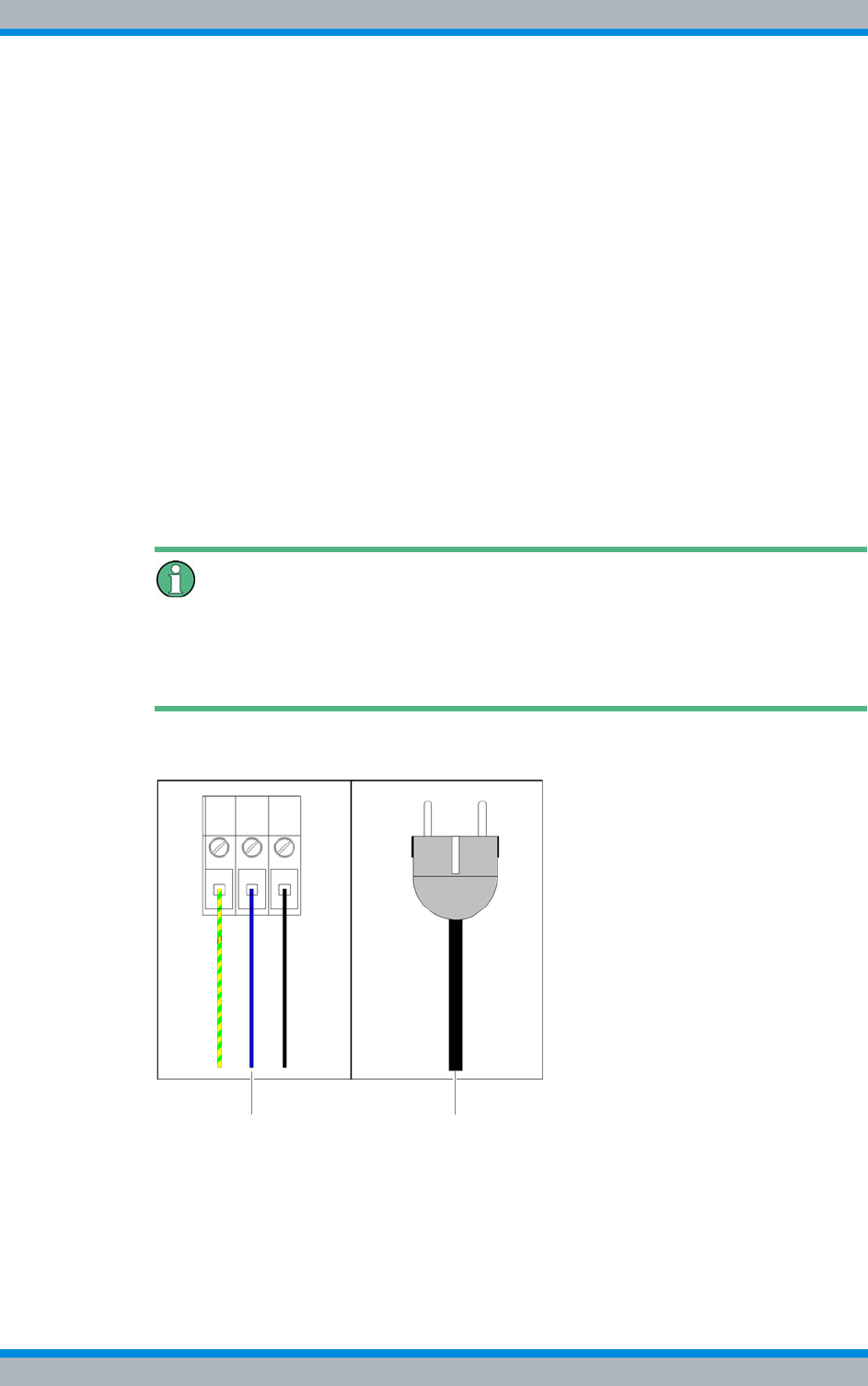
DIB-500 R4.1 Setup and commissioning
Connection to the electrical system
112 Installation, Operation and Service Manual 90DIB500R41IM_FCC02 – 99.1
5.6.3.2 Connecting the VAC voltage supply – optional
The DIB-500 R4.1 with VAC expansion (optional) provides a power supply cable via the
equipment rack for each rectifier module. Rectifier modules are already connected to
the mounting frame and can be connected to the voltage source on site.
With a VAC voltage supply (optional), the DIB-500 R4.1 can be connected to the voltage
source on site in the following connection variants:
|to a fixed connection (e. g. distributor box),
with this connection variant, an easily accessible separator must be available in the
voltage supply circuit of the voltage source, such as a fuse in the sub-distribution
|or with a plug with earthing contact to a mains socket.
with this connection variant, the mains socket must be easily accessible and located
as close to the product as possible. The length of the voltage supply cable limits the
possible distance. The length of the voltage supply cable is 2.5 m.
One plug with earthing contact in compliance with CEE 7/VII for each integrated rectifier
module is included in the scope of delivery and already installed upon delivery. The volt-
age supply cable(s) are identified according to the related rectifier module, e.g. "PSU1".
Removing plugs with earthing contact
The plug with earthing contact can be removed when the DIB-500 R4.1 is to be con-
nected to a fixed connection (e.g. distributor box). In this case, the strand ends of the
voltage supply cable/s must be fitted with end sleeves for strands.
Figure 5.17 shows the possible connection variants for the VAC- voltage supply
Figure 5.17 VAC voltage supply – connection variants
Proceed as follows to connect the voltage supply cable:
Preparation:
✓The site must be prepared in compliance with the document "Site Requirements".
✓The equipment rack must be connected to the grounding system.
Fixed connection Mains socket
Installation, Operation and Service Manual 90DIB500R41IM_FCC02 – 99.1 113
DIB-500 R4.1 Setup and commissioning
Connecting Ethernet cables
✓The voltage source on site must be de-energised.
✓The toggle switches must be set to the "Off" position ("downward" switch position).
✓The top cover of the equipment rack must have been removed.
✓Depending on the connection variant, the plug with earthing contact may have to
be removed already.
✓The reference potential must have been defined.
Carry out the following steps:
Cable damage
If cables are routed over sharp edges or in bending radiuses too small for the cables,
the cables may be damaged.
➔Never route cables over sharp edges and always maintain to the bending radius.
Risk of damage
The product may be damaged if the live wires of the voltage supply cable are connected
without grounding.
➔Connect the green-yellow grounding cable of the grounding conductor first.
➔Connect the power supply cable(s) at installed rectifier modules – depending on
the connection variant – with the voltage source, see Figure 5.17 on page 112.
✓The voltage supply cable has been connected.
Switching on the Voltage Source Later on
Since the commissioning of the network requires additional work steps that need to be
performed in the equipment rack, the voltage source must stay switched off for the time
being. Switching on the voltage source is required only later on for the configuration.
5.7 Connecting Ethernet cables
All network elements of the ACCESSNET®-T IP network are connected to an IP trans-
port network using an external layer-3 switch. For this reason, operating the
DIB-500 R4.1 requires that Ethernet cables are connected according to the overview in
section Figure 3.17 on page 46 to the DIB-500 R4.1. In addition, the Ethernet cables
must be fastened with cable ties in the equipment rack.
As a router, the layer-3 switch ensures the communication between the individual net-
work constituents that each form a separate subnetwork. In addition, the layer-3 switch
facilitates the integration into existing IP transport networks.

DIB-500 R4.1 Setup and commissioning
Installing the GPS antenna
114 Installation, Operation and Service Manual 90DIB500R41IM_FCC02 – 99.1
Requirements for the layer-3 switch for controller redundancy
For controller redundancy (see section 3.1.9.3 on page 61), it is required that the layer-
3 switch supports the Multiple Spanning Tree Protocol (MSTP) in accordance with IEEE
802.1Q2.
If network elements must be connected to a layer-3 switch, it is required that the config-
uration of the layer-3 switch has been completed.
Connecting network elements with the layer-3 switch
Preparation:
✓The initial download must have been completed on the corresponding network ele-
ment.
✓The layer-3 switch must have been configured project-specific.
Carry out the following steps:
Routing of the Ethernet Cable
When connecting the Ethernet cable, ensure that cables are not routed in front of the
fan unit so they do not impair the replacement of fan unit components.
➔Connect the Ethernet cable to the Ethernet port of the layer-3 switch and to the cor-
responding Ethernet port of the network element, refer to section 3.1.5 on page 45.
✓You have successfully connected the network element to the layer-3 switch.
5.8 Installing the GPS antenna
The scope of delivery of the product comprises an antenna mounting kit including the
GPS antenna. A third-party GPS antenna may be used instead. In this case, heed the
documentation of the third-party devices to prevent adverse effects and malfunctions of
the product and other products connected to it.
The GPS antenna included in the scope of delivery is appropriate for the following
installation sites:
|on the roof of a building
|at the wall of a building
|on an antenna mast
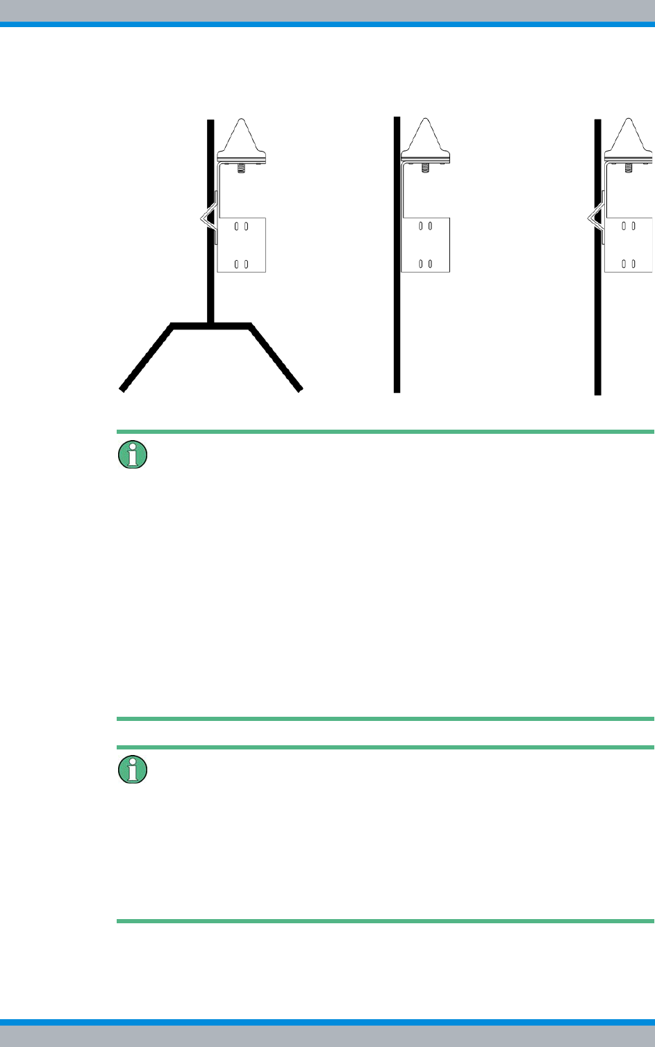
Installation, Operation and Service Manual 90DIB500R41IM_FCC02 – 99.1 115
DIB-500 R4.1 Setup and commissioning
Installing the GPS antenna
Figure 5.18 shows an example of installing the GPS antenna supplied.
Figure 5.18 Example: installation of the GP antenna supplied (roof, wall, mast installation)
Responsibility for the installation, commissioning and maintenance of the GPS
antenna
The operating company is responsible for the proper installation, commissioning and
maintenance of the GPS antenna unless this is an integral part of the contract con-
cluded with Rohde & Schwarz Professional Mobile Radio GmbH.
The operator is responsible for ensuring that:
|the installation location of the GPS antenna is appropriate for installing an antenna,
e.g. the roof or wall of a building or an antenna mast.
|an antenna mast, if used, including any required retaining elements are installed in
such a way that they are protected against outside influences, e.g. a storm.
|equipment for overload protection and lightning protection of the GPS antenna has
been provided at the installation site. In this case, ensure that the amplifier inte-
grated into the GPS antenna is supplied VDC voltage via the antenna cable.
Additional GPS antenna recommended
For DIB-500 R4.1 with more than two TIB transceiver modules and controller redun-
dancy, the use of an additional GPS antenna is recommended to ensure the GPS syn-
chronicity of the entire base station in case the active controller fails.
Without GPS satellite reception the proper operation of the DIB-500 R4.1 is ensured for
one year (depending on the ambient conditions) if a GPS signal was received before at
least once.

DIB-500 R4.1 Setup and commissioning
Installing the GPS antenna
116 Installation, Operation and Service Manual 90DIB500R41IM_FCC02 – 99.1
Proceed as follows to install the GPS antenna:
Preparation:
✓The site must be prepared in compliance with the document "Site Requirements".
✓The tools, auxiliary means and materials specified must be available, refer to
section 5.2 on page 90.
✓The antenna mounting kit including the GPS antenna supplied must be available.
Carry out the following steps:
1. If you are installing the antenna on a mast, fasten the fibre ribbon on the antenna
mast as an additional means of securing the GPS antenna against slipping.
The GPS antenna must not be installed on the antenna mast of the TX antenna of
a base station. Otherwise reliable decoupling cannot be guaranteed.
➔Exclusively install the GPS antenna in appropriate locations such as on building
roofs.
2. Position the GPS antenna at the installation site.
3. When installing the antenna on a mast, use a size 1 cross-head screwdriver to fas-
ten the mounting clamp on the holder of the GPS antenna with the cross-head
screws, refer to Figure 5.19. The mounting clamp can be installed on the holder of
the GPS antenna either horizontally or vertically.
Figure 5.19 GPS antenna – installing the mounting clamp
4. Tighten the corresponding fastening screws to install the GPS antenna at the
installation site. Use a size 4 Allen wrench for this purpose.
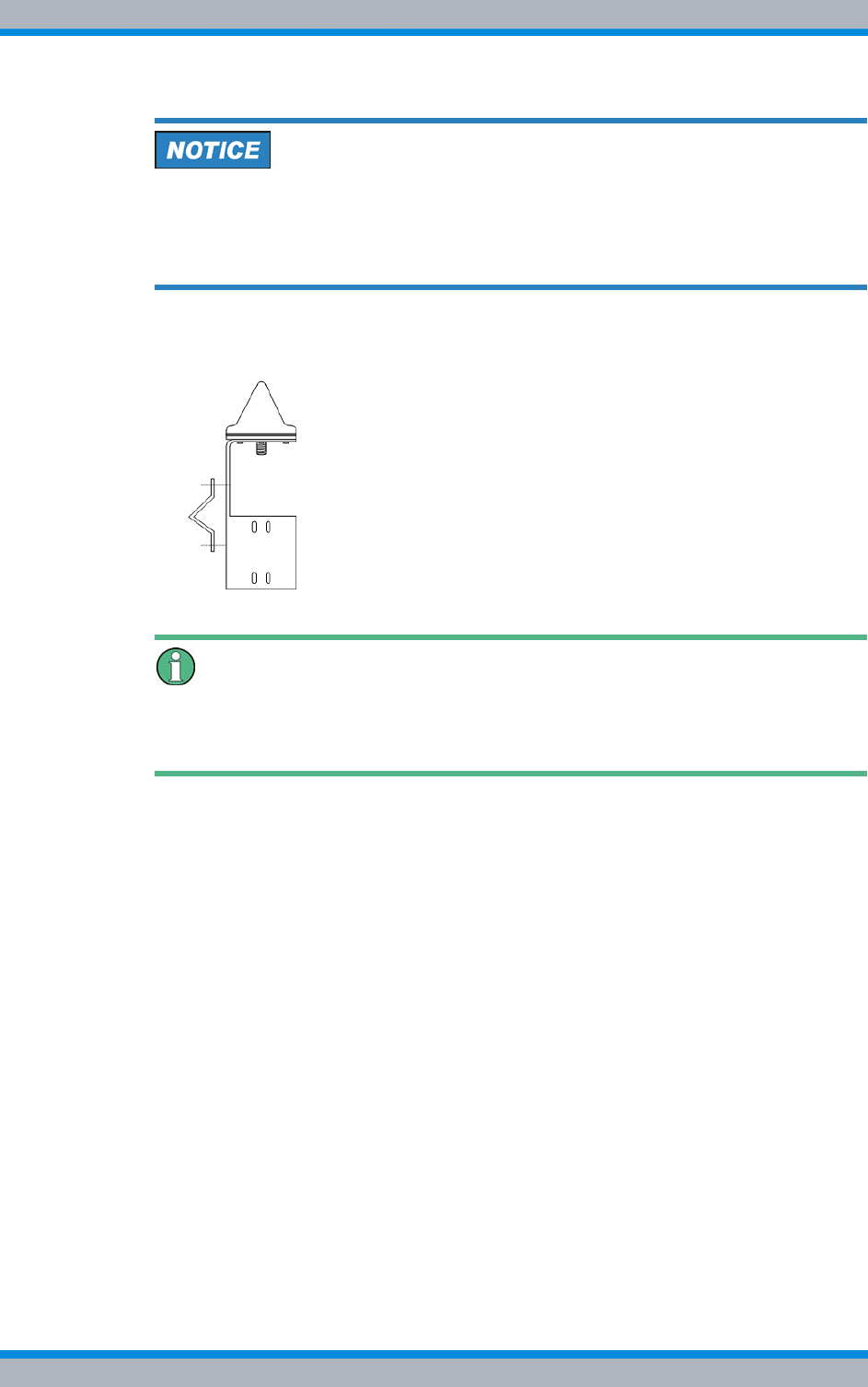
Installation, Operation and Service Manual 90DIB500R41IM_FCC02 – 99.1 117
DIB-500 R4.1 Setup and commissioning
Installing the GPS protector - optional
Cable damage
If cables are routed over sharp edges or in bending radiuses too small for the cables,
the cables may be damaged.
➔Never route cables over sharp edges and always maintain to the bending radius.
5. Connect the cable of the GPS antenna to the corresponding connector on the bot-
tom of the GPS antenna, refer to Figure 5.20.
Figure 5.20 Connecting the cable of the GPS antenna
Additional protection against tensile stress
If required, use appropriate mechanisms as an additional means of protecting long GPS
antenna cables against tensile stress.
6. Protect the GPS antenna cable against tensile stress by securing it to the holder of
the GPS antenna with cable ties.
7. After the installation of the GPS antenna, it is recommended to check the installa-
tion site of the GPS antenna, see section 7.6.1 on page 159.
✓You have successfully installed the GPS antenna.
5.9 Installing the GPS protector - optional
To protect the GPS antenna input against overvoltage (caused by lightning, for exam-
ple), a GPS protector is optionally available that should be used in combination with a
lightning surge protector to provide for optimum overvoltage protection. The GPS pro-
tector can be ordered separately.
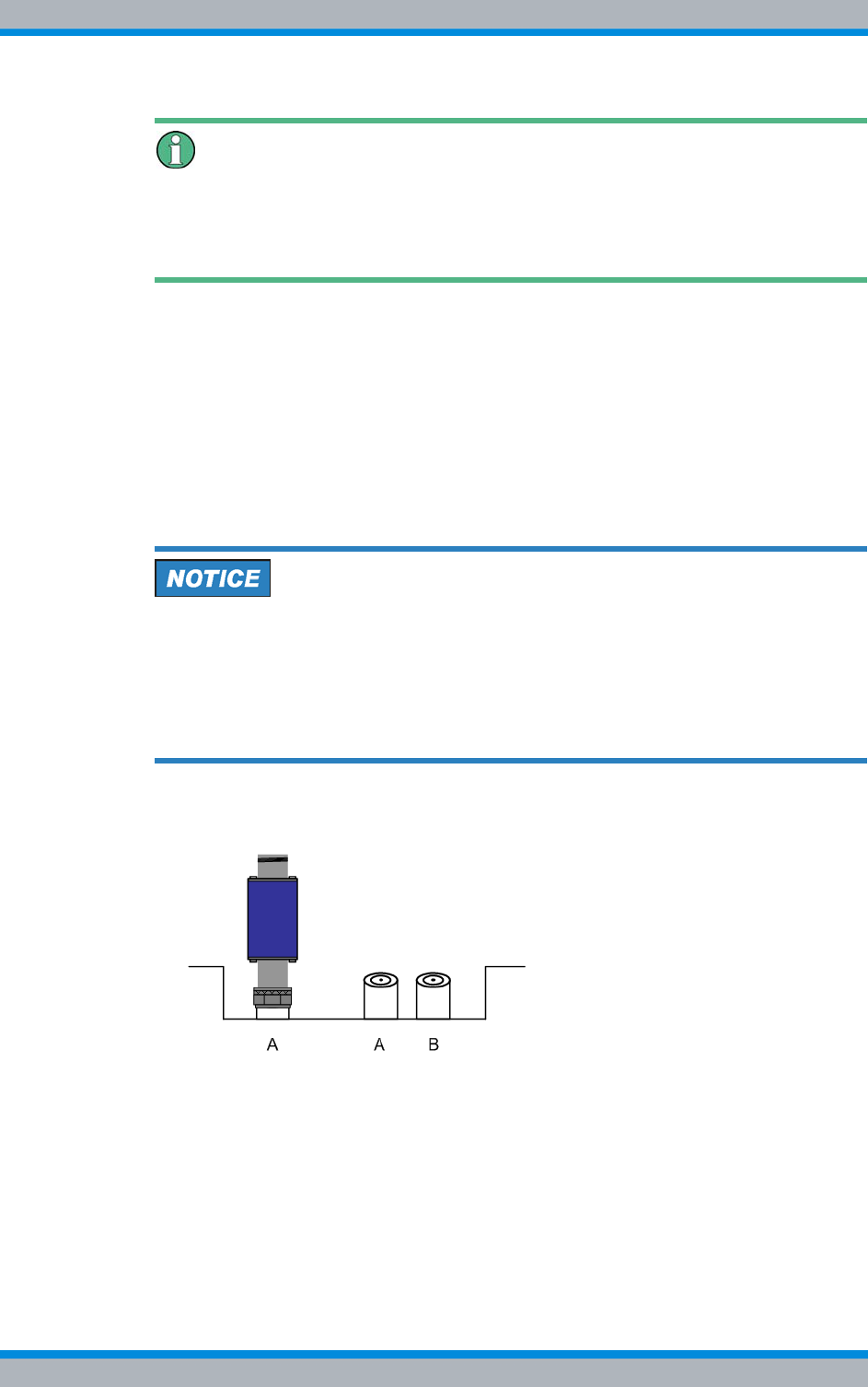
DIB-500 R4.1 Setup and commissioning
Installing the GPS protector - optional
118 Installation, Operation and Service Manual 90DIB500R41IM_FCC02 – 99.1
GPS overvoltage concept
When using the GPS protector, the GPS supply lines at the entry into the building
should be safeguarded against high overvoltages by a grounded lightning surge protec-
tor.
The GPS protector is a passive and thus maintenance-free hardware component
mounted on the GPS antenna connection of the equipment rack.
Installing the GPS protector
Preparation:
✓The site must be prepared in compliance with the document "Site Requirements".
✓The equipment rack must be connected to the grounding system.
✓The toggle switches must be set to the "Off" position ("downward" switch position).
Carry out the following steps:
Risk of damage from electrostatic discharge (ESD)
The base station can be damaged if antennas are connected or disconnected during
the switched-on state. The GPS antenna connection is particularly sensitive to electro-
static discharge (ESD).
➔Ensure that the base station is switched off before connecting or disconnecting
antennas.
➔Install the GPS protector on the GPS antenna connection applying a tightening
torque of 100 Ncm using a size 18 dynamometric key.
Figure 5.21 GPS antenna connection with GPS protector
✓You have successfully installed the GPS protector.
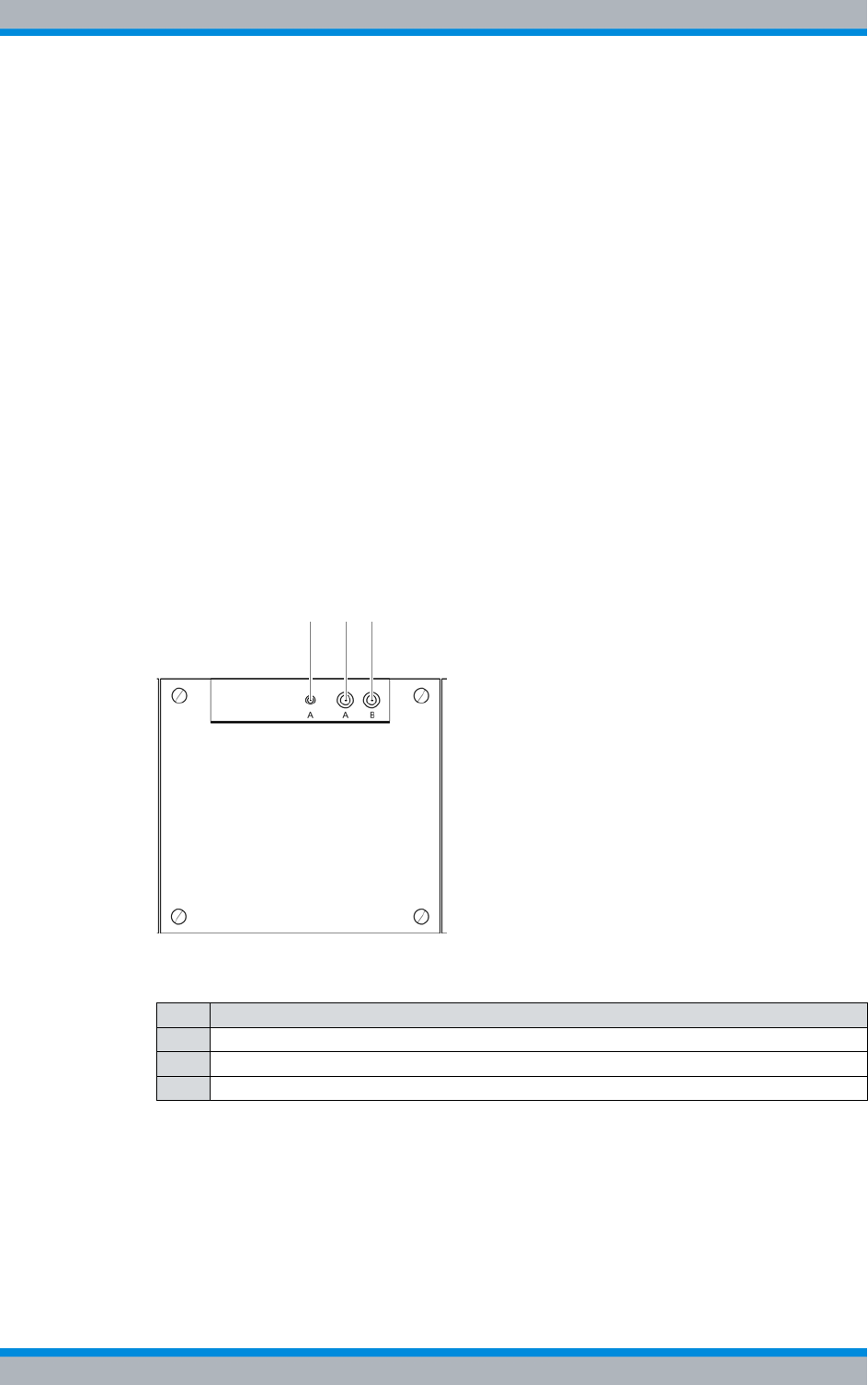
Installation, Operation and Service Manual 90DIB500R41IM_FCC02 – 99.1 119
DIB-500 R4.1 Setup and commissioning
Connecting antennas
5.10 Connecting antennas
The following sections contains a description of the wiring diagrams for the FlexibleTx
variant.
|Connecting antennas (GPS and TETRA)
|Connection of external antenna coupling systems – Optionally, only FlexibleTx vari-
ant
5.10.1 Connecting antennas (GPS and TETRA)
Each equipment cabinet features three antenna connectors – two for TETRA antennas
(A and B) and one GPS antenna connector. All the antenna connectors are routed from
the front of the respective TIB transceiver module or ACS to the top of the respective
equipment cabinet.
To ensure proper operation of the antenna system, you have to connect the TETRA
antennas (antenna A and B (optional for diversity)) as well as the GPS antenna.
Figure 5.22 shows the antenna connections on the upper side of the equipment rack.
The following table describes it in detail.
Figure 5.22 Antenna connectors – equipment cabinet top view
The procedure for connecting the antenna(s) to one equipment rack is described in the
following.
Proceed as follows to connect an antenna / antennas:
Preparation:
✓The site must be prepared in compliance with the document "Site Requirements".
Table 5.13 Legend: Antenna connections – top view of equipment rack
No. Description
1 GPS antenna connector
2 TETRA antenna connection A
3 TETRA antenna connection B – optional, for diversity
2 31
DIB-500 R4.1 Setup and commissioning
Connecting antennas
120 Installation, Operation and Service Manual 90DIB500R41IM_FCC02 – 99.1
✓The equipment rack must be connected to the grounding system.
✓Appropriate antenna cables of the required lengths must be available.
✓The toggle switches must be set to the "Off" position ("downward" switch position).
Carry out the following steps:
Cable-specific tools and process steps
The required tools and process steps depend on the antenna cable used and the
related connector.
Cable damage
If cables are routed over sharp edges or in bending radiuses too small for the cables,
the cables may be damaged.
➔Never route cables over sharp edges and always maintain to the bending radius.
Risk of damage from electrostatic discharge (ESD)
The base station can be damaged if antennas are connected or disconnected during
the switched-on state. The GPS antenna connection is particularly sensitive to electro-
static discharge (ESD).
➔Ensure that the base station is switched off before connecting or disconnecting
antennas.
➔Connect the required antennas on the upper side of the equipment rack, refer to
Figure 5.22 on page 119.
The following options are available:
|Connect the GPS antenna:
– to the optional GPS protector (recommended),
– directly to the corresponding connector.
|TETRA antenna(s): Directly connected to corresponding connector/connectors.
✓The antennas have thus been connected.
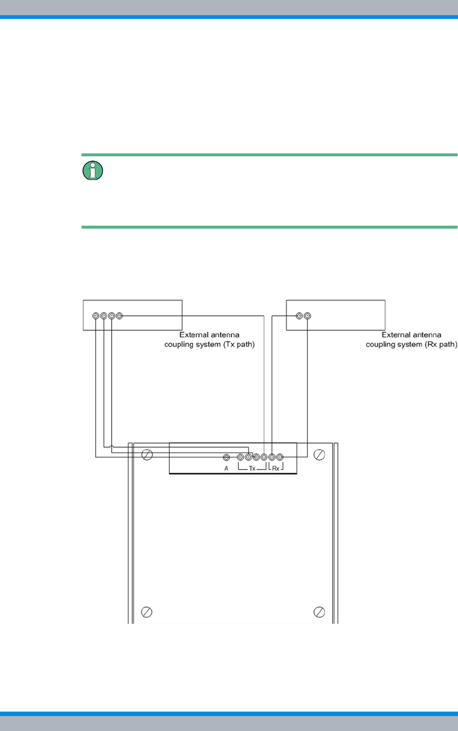
Installation, Operation and Service Manual 90DIB500R41IM_FCC02 – 99.1 121
DIB-500 R4.1 Setup and commissioning
Connecting antennas
5.10.2 Connection of external antenna coupling systems – Optionally, only
FlexibleTx variant
In the FlexibleTx variant, antenna coupling was performed project-specifically according
to the desires and requirements of the network operator via external antenna coupling
systems. In this way, the DIB-500 R4.1, e.g. can be connected to existing antenna cou-
pling systems.
Requirements for external antenna coupling systems.
The requirements on external antenna coupling systems are described in the site
requirements.
Figure 5.23 shows by way of an example the connection of an external antenna cou-
pling system to the FlexibleTx variant of the DIB-500 R4.1. The connections of external
antenna coupling systems to the DIB-500 R4.1 and to the antenna(s) are to be defined
to match the project.
Figure 5.23 Connection of an external antenna coupling system
DIB-500 R4.1 Setup and commissioning
Connecting antennas
122 Installation, Operation and Service Manual 90DIB500R41IM_FCC02 – 99.1
Connect external antenna coupling system
Preparation:
✓The site must be prepared in compliance with the document "Site Requirements".
✓The equipment rack must be connected to the grounding system.
✓Appropriate antenna cables of the required lengths must be available.
✓The toggle switches must be set to the "Off" position ("downward" switch position).
Carry out the following steps:
Cable-specific tools and process steps
The required tools and process steps depend on the antenna cable used and the
related connector.
Cable damage
If cables are routed over sharp edges or in bending radiuses too small for the cables,
the cables may be damaged.
➔Never route cables over sharp edges and always maintain to the bending radius.
Risk of damage from electrostatic discharge (ESD)
The base station can be damaged if antennas are connected or disconnected during
the switched-on state.
➔Ensure that the base station is switched off before connecting or disconnecting
antennas.
➔Connect the external antenna coupling system to the upper side of the equipment
rack, see Figure 5.23 on page 121.
✓The external antenna coupling system is connected.
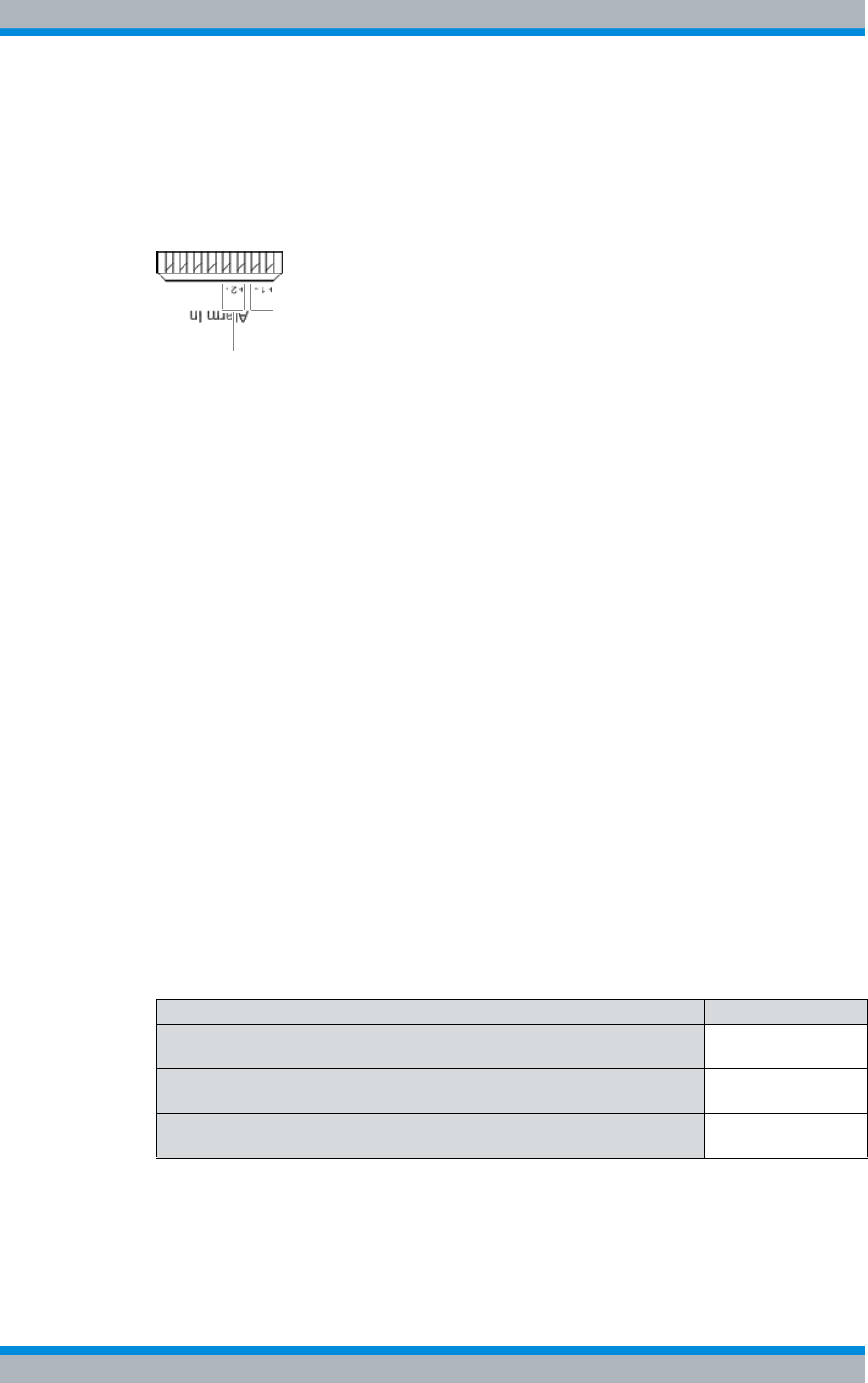
Installation, Operation and Service Manual 90DIB500R41IM_FCC02 – 99.1 123
DIB-500 R4.1 Setup and commissioning
Connecting external alarm sensors (LSA+)
5.11 Connecting external alarm sensors (LSA+)
The DIB-500 R4.1 features two alarm inputs that are connected via the "Alarm in" LSA+
strip on the E1 connection board. The assignment of the alarm inputs is controlled
project-specifically.
Figure 5.24 Alarm inputs (LSA+)
Proceed as follows to connect external alarm sensors:
Preparation:
✓The connecting cables provided must comply with the "Site requirements" docu-
ment.
Carry out the following steps:
➔Connect the corresponding wires of the external alarm sensors to the terminals on
the LSA+ strip, refer to Figure 5.24 on page 123.
✓You have successfully connected external alarm sensors.
5.12 Connecting external alarms – optional, with VAC or
alerting expansion
If the DIB-500 R4.1 is equipped with a VAC or alarm system expansion, it features six
digital alarm inputs and six digital alarm outputs that are connected with the alarm input/
output module, see Figure 5.25 on page 124.
The alarm inputs/outputs can be configured as required. The alarm inputs/outputs to be
used can be defined through connection to the corresponding terminals. The alarms are
signalled with the corresponding severity via the alarm outputs.
The tasks listed in the following table must be performed for the connection of external
alarms.
2 1
Table 5.14 Overview of the tasks to be performed (connecting external alarms)
Tasks/work steps Described in
Removing the top cover of the equipment rack Section 5.12.1 on
page 124
Connecting external alarms Section 5.12.2 on
page 126
Mounting the top cover of the mounting frame Section 5.12.3 on
page 128
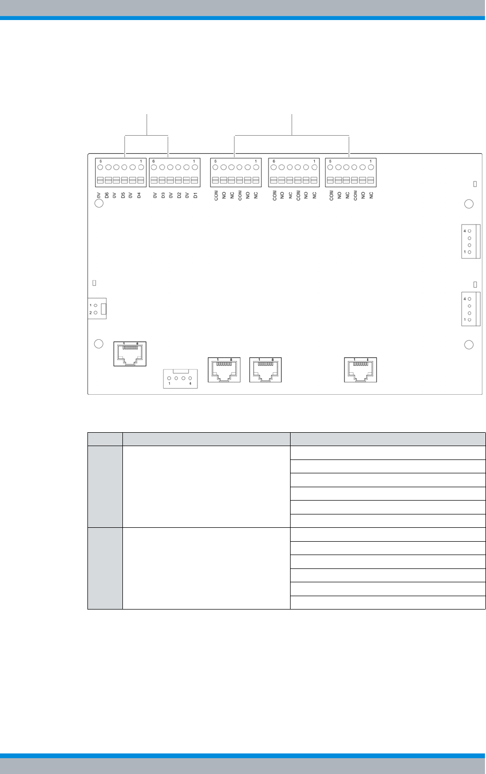
DIB-500 R4.1 Setup and commissioning
Connecting external alarms – optional, with VAC or alerting expansion
124 Installation, Operation and Service Manual 90DIB500R41IM_FCC02 – 99.1
Figure 5.25 shows the alarm inputs/outputs of the alarm input/outputs of the alarm input/
output module. The following table describes these indicators in detail.
Figure 5.25 Alarm input/output module – alarm inputs/outputs
5.12.1 Removing the top cover of the equipment rack
The alarm input/output module is installed in the mounting frame, refer to 3.1.1.5 on
page 40. The top cover of the mounting frame must be opened to be able to access the
alarm input/output module. The top cover of the equipment rack must be removed to be
able to access the mounting frame.
Table 5.15 Legend: Alarm input/output module – alarm inputs/outputs
No. Description Alarm input/output
1 Alarm inputs (I) I1
I2
I3
I4
I5
I6
2 Alarm outputs (O) O1
O2
O3
O4
O5
O6
1 2
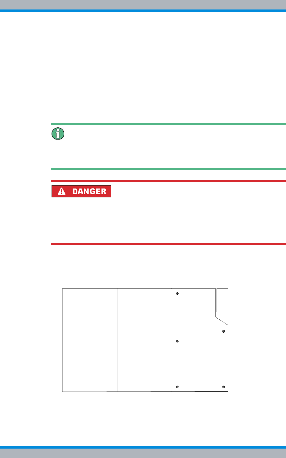
Installation, Operation and Service Manual 90DIB500R41IM_FCC02 – 99.1 125
DIB-500 R4.1 Setup and commissioning
Connecting external alarms – optional, with VAC or alerting expansion
The top cover of the mounting frame is secured with five mounting screws.
Proceed as follows to remove the top cover of the mounting frame:
Preparation:
✓The voltage source on site must be de-energised.
✓The toggle switches must be set to the "Off" position ("downward" switch position).
✓The top cover of the equipment rack must have been removed.
✓The tools, auxiliary means and materials specified must be available, refer to
section 5.2 on page 90.
Carry out the following steps:
Keeping materials
Keep all the materials such as fastening screws in a safe place. You will need them
again.
Risk of electric shock
Electric shock when touching live parts. Hardware components in the equipment cabi-
net are live.
➔When performing work in the equipment cabinet, ensure that the voltage source on
site is switched off. This must have been checked with a voltmeter.
1. Loosen the mounting screws of the top cover of the mounting frame using a size 1
cross-head screwdriver, refer to Figure 5.26.
Figure 5.26 Mounting frame mounting screws
2. Remove the top cover of the mounting frame.
✓You have successfully removed the top cover of the mounting frame.
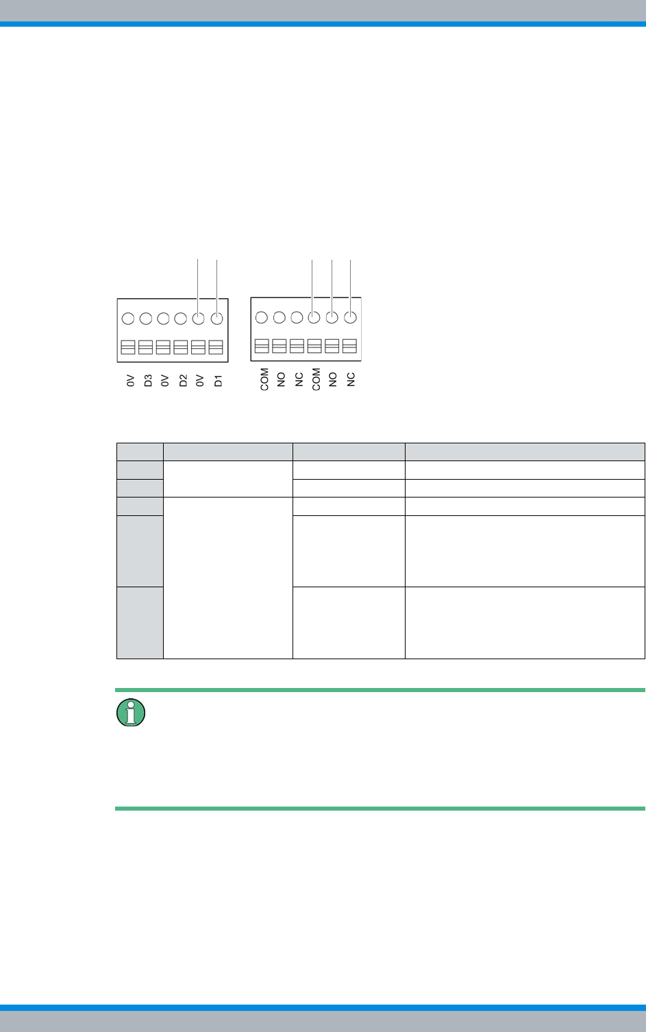
DIB-500 R4.1 Setup and commissioning
Connecting external alarms – optional, with VAC or alerting expansion
126 Installation, Operation and Service Manual 90DIB500R41IM_FCC02 – 99.1
5.12.2 Connecting external alarms
Depending on the desired alarm signalling, external alarms can be connected to the ter-
minals of the alarm inputs/outputs. For the alarm outputs you can influence, in which
cases alarms are to be signalled. This is determined via the corresponding connection
combinations of the terminals, refer to Figure 5.27.
Figure 5.27 shows examples of the clamps for connecting external alarms. The follow-
ing table describes these indicators in detail.
Figure 5.27 Terminals for connecting external alarms (example)
Alarm jumper
If an external alarm is not connected, one alarm jumper must be mounted per alarm
input to short-circuit the contacts. When external alarms are connected, the jumper
must be removed from the corresponding terminal.
Proceed as follows to connect external alarms:
Preparation:
✓The voltage source on site must be de-energised.
✓The toggle switches must be set to the "Off" position ("downward" switch position).
✓The connecting cables must be available.
✓The tools, auxiliary means and materials specified must be available, refer to
section 5.2 on page 90.
Table 5.16 Legend: terminals for connecting external alarms (example)
No. Alarm input/output Terminal Description
1 Alarm input 0V Grounding (digital input 1)
2 D1 Digital input 1
3 Alarm output COM Common – centre contact
4 NO normally open – switch open if an alarm
is not signalled
e.g. a connected line will light up if an
alarm occurs
5 NC normally closed – switch closed if an
alarm is signalled
e.g. a connected lamp will go out if an
alarm occurs
13 42 5
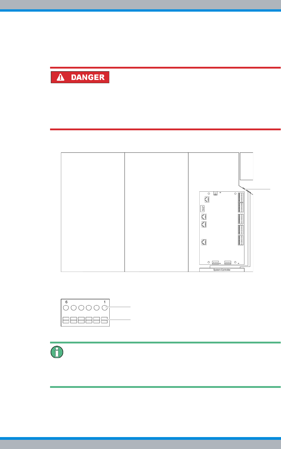
Installation, Operation and Service Manual 90DIB500R41IM_FCC02 – 99.1 127
DIB-500 R4.1 Setup and commissioning
Connecting external alarms – optional, with VAC or alerting expansion
✓The top cover of the mounting frame must have been removed.
✓The top cover of the equipment rack must have been removed.
Carry out the following steps:
Risk of electric shock
Electric shock when touching live parts. Hardware components in the equipment cabi-
net are live.
➔When performing work in the equipment cabinet, ensure that the voltage source on
site is switched off. This must have been checked with a voltmeter.
1. Route the cables of the external alarms through the corresponding grommet.
Figure 5.28 Mounting frame grommet (top view)
2. Cautiously press the lever (1) downward to open the clamps of the connectors (2).
Figure 5.29 Alarm input/output module - connection
Clamp specification
The terminals of the alarm input/output module are designed for cable cross sections of
0.5-2.0mm
2 (20 - 14 AWG).
3. Connect the wires of the external alarms to the corresponding clamps of the alarm
input/output module, refer to Figure 5.25 on page 124.
2
1
DIB-500 R4.1 Setup and commissioning
Connecting external alarms – optional, with VAC or alerting expansion
128 Installation, Operation and Service Manual 90DIB500R41IM_FCC02 – 99.1
4. Ensure that all the terminals of vacant alarm inputs are connected through alarm
jumpers.
Strain relief of connected cables / connecting lines
When connecting cables and connecting lines, you must ensure that they are protected
against tensile strain.
5. Fasten the connected cables in the equipment rack in such a way that they are pro-
tected against tensile strain, e. g. by using cable ties.
✓You have successfully connected external alarms.
5.12.3 Mounting the top cover of the mounting frame
The top cover of the mounting frame must be mounted again for normal operation.
Proceed as follows to mount the top cover of the mounting frame:
Preparation:
✓The network element must have been put out of operation temporarily, refer to sec-
tion 8.1 on page 163.
✓The tools, auxiliary means and materials specified must be available, refer to
section 5.2 on page 90.
✓You need the mounting screws you removed before.
Carry out the following steps:
Risk of electric shock
Electric shock when touching live parts. Hardware components in the equipment cabi-
net are live.
➔When performing work in the equipment cabinet, ensure that the voltage source on
site is switched off. This must have been checked with a voltmeter.
1. Position the top cover of the mounting frame.
2. Tighten the mounting screws of the upper cover of the mounting frame. Use a size
1 cross-head screwdriver for this purpose, refer to Figure 5.26.
✓You have successfully mounted the top cover of the mounting frame.

Installation, Operation and Service Manual 90DIB500R41IM_FCC02 – 99.1 129
DIB-500 R4.1 Setup and commissioning
Mounting the top cover of the equipment rack
5.13 Mounting the top cover of the equipment rack
The top cover of the equipment rack must be mounted again for normal operation.
Proceed as follows to mount the top cover of the equipment rack:
Preparation:
✓The tools, auxiliary means and materials specified must be available, refer to
section 5.2 on page 90.
✓You need the mounting screws you removed before.
Carry out the following steps:
1. Position the equipment rack top cover.
2. Tighten the mounting screws of the equipment rack top cover. Use a coin to do so,
refer to Figure 5.3.
3. Fasten the mounting screws of the equipment rack grommet again. Use the size 2
cross-head screwdriver for this purpose, refer to Figure 5.2.
✓You have successfully mounted the equipment rack top cover.
5.14 Switching on the voltage source
Before the product can be switched on, the voltage source must be switched on. The
procedure for switching on the voltage source depends on the circumstances at the
respective installation site.
Proceed as follows to switch on the voltage source:
Preparation:
✓The equipment rack must be connected with the grounding system of the voltage
source at the installation site.
✓The antennas must be connected.
✓The external alarms must be connected.
Carry out the following steps:
➔Switch on the voltage source via the corresponding equipment at the installation
site.
➥The equipment rack is energised. TIB, ACS and fans continue to be switched off.
➥If installed, the SC200 is switched on. The display window of the SC200 lights
up.
✓The procedure for switching on the voltage source has been completed.
5.15 Switching on the DIB-500 R4.1
If the voltage source at the location is switched on, the equipment rack is already ener-
gised even though TIB, ACS and fans continue to be switched off. For this reason, the
DIB-500 R4.1 is not yet switched on and operational.
The product is switched on via an on/off switch in the upper part of the equipment cabi-
net. After the voltage supply has been switched on, all the connected hardware compo-
nents will automatically start. Connections will be enabled. After about three to five
minutes, all hardware components have started up and are ready for operation.
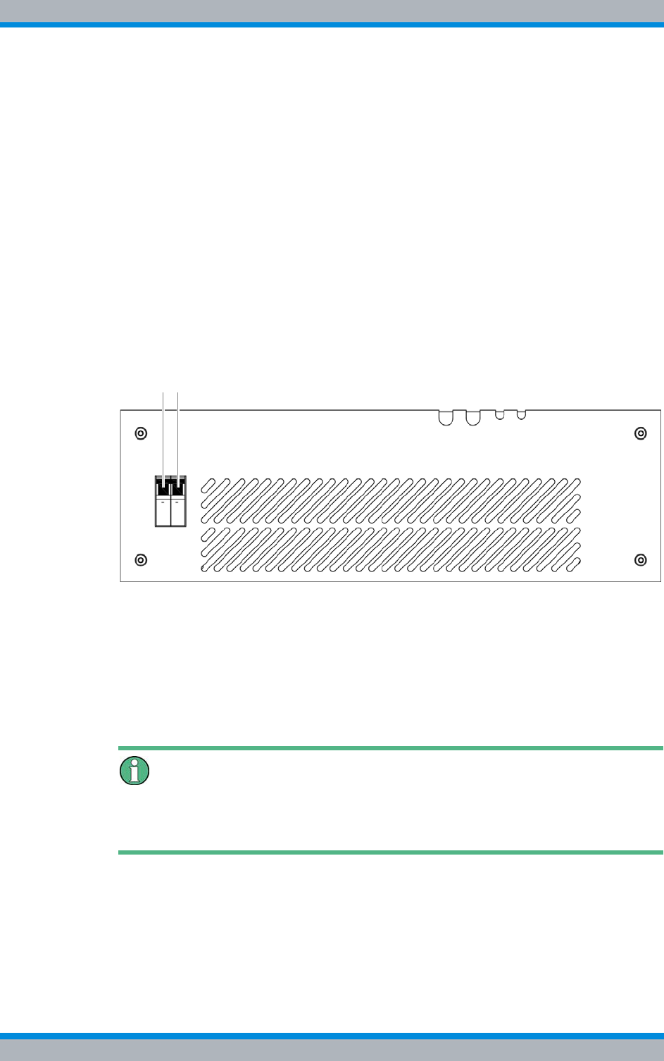
DIB-500 R4.1 Setup and commissioning
Switching on the DIB-500 R4.1
130 Installation, Operation and Service Manual 90DIB500R41IM_FCC02 – 99.1
To switch on the product, the connections must have been made properly and the volt-
age source at the installation site must have been switched on already.
Switching on DIB-500 R4.1
Preparation:
✓The equipment rack must be connected with the earthing system, see section 5.6.1
on page 107.
✓The equipment rack must be connected to the voltage source at the location, see
section 5.6.3 on page 110.
✓The voltage source at the location must be switched on, see section 5.14 on
page 129.
✓All required connecting cables and antennas must be connected, see chapter 5 on
page 89.
Carry out the following steps:
➔Switch the on/off switch upward to switch on the DIB-500 R4.1, see Figure 5.30.
Figure 5.30 On/off switch
➥The TIB transceiver module starts up.
➥The fans are switched on.
➥The antenna coupling system (ACS) is supplied with voltage via the TIB trans-
ceiver modules.
✓You have successfully switched on the DIB-500 R4.1.
Performing function tests
After performing the described procedure/s, the described function tests should be per-
formed to ensure the proper operation of the product, refer to chapter 7 on page 151.
1 2
Installation, Operation and Service Manual 90DIB500R41IM_FCC02 – 99.1 131
DIB-500 R4.1 Configuration
Configuring the software
6 Configuration
The following chapter describes the procedure for the proper configuration of the prod-
uct. The product is already configured upon delivery. After a component replacement or
due to project-specific circumstances, it may still be necessary to perform configuration
steps.
The tasks listed in the following table must be performed for the configuration of the
DIB-500 R4.1.
6.1 Configuring the software
Prerequisite for configuring the network element (as a preparatory measure for the net-
work-specific configuration of the network with the aid of the NMC-515 Configuration-
Manager network management client) is the completed commissioning of the network
element, see chapter 5 on page 89.
The tasks listed in the following table must be performed for the configuration of the
software.
Table 6.1 Overview of the tasks to be performed
Tasks/work steps Described in
Configuring the software Preparatory measures Switching on the voltage
source Section 6.1.2 on
page 132
Switching on the
DIB-500 R4.1
Connecting the service com-
puter to the TIB transceiver
module
Deleting the ARP buffer Section 6.1.3 on
page 134
Configuring and generating network configurations via the
NMC-515 ConfigurationManager Section 6.1.4 on
page 134
Creating the download repository Section 6.1.5 on
page 135
Adapting IP addresses (with more than one transceiver mod-
ule) Section 6.1.6 on
page 135
Performing an initial download via NMC-522 DownloadMan-
ager Section 6.1.7 on
page 142
Adjusting a cavity coupler –
optional (cavity variant only) Setting the output rating Section 6.2.2 on
page 144
Measuring and checking the carriers (impedance adjustment) Section 6.2.3 on
page 146
Table 6.2 Overview of the tasks to be performed (Configuring the software)
Tasks/work steps Described in
Preparatory measures Switching on the voltage source Section 6.1.2 on
page 132
Switching on the DIB-500 R4.1
Connecting the service computer to
the TIB transceiver module
DIB-500 R4.1 Configuration
Configuring the software
132 Installation, Operation and Service Manual 90DIB500R41IM_FCC02 – 99.1
6.1.1 Work equipment
Table 6.3 provides an overview of the work equipment required for the steps in this
chapter.
Service computers not included in the scope of delivery
Service computers are not part of the product's scope of supply and are available sepa-
rately.
6.1.2 Preparatory measures
The preparatory measures listed in the following table must be performed for the config-
uration of the software.
Deleting the ARP buffer Section 6.1.3 on
page 134
Configuring and generating network configurations via the NMC-515
ConfigurationManager Section 6.1.4 on
page 134
Creating the download repository Section 6.1.5 on
page 135
Adapting IP addresses (with more than one transceiver module) Section 6.1.6 on
page 135
Performing an initial download via NMC-522 DownloadManager Section 6.1.7 on
page 142
Table 6.2 Overview of the tasks to be performed (Configuring the software)
Tasks/work steps Described in
Table 6.3 Overview of work equipment (Configuration)
Work step Work equipment
Configuring the software |according to the configured service computer, refer to the
Configuration Manual "Service Computer for
ACCESSNET®-T IP"
|Straight through ethernet cable
Table 6.4 Overview of preparatory measures (Configuring the software)
Tasks/work steps Described in
Switching on the voltage source Section 5.14 on
page 129
Switching on the DIB-500 R4.1 Section 5.15 on
page 129
Connecting the service computer to the TIB transceiver module Section 6.1.2.1
on page 133
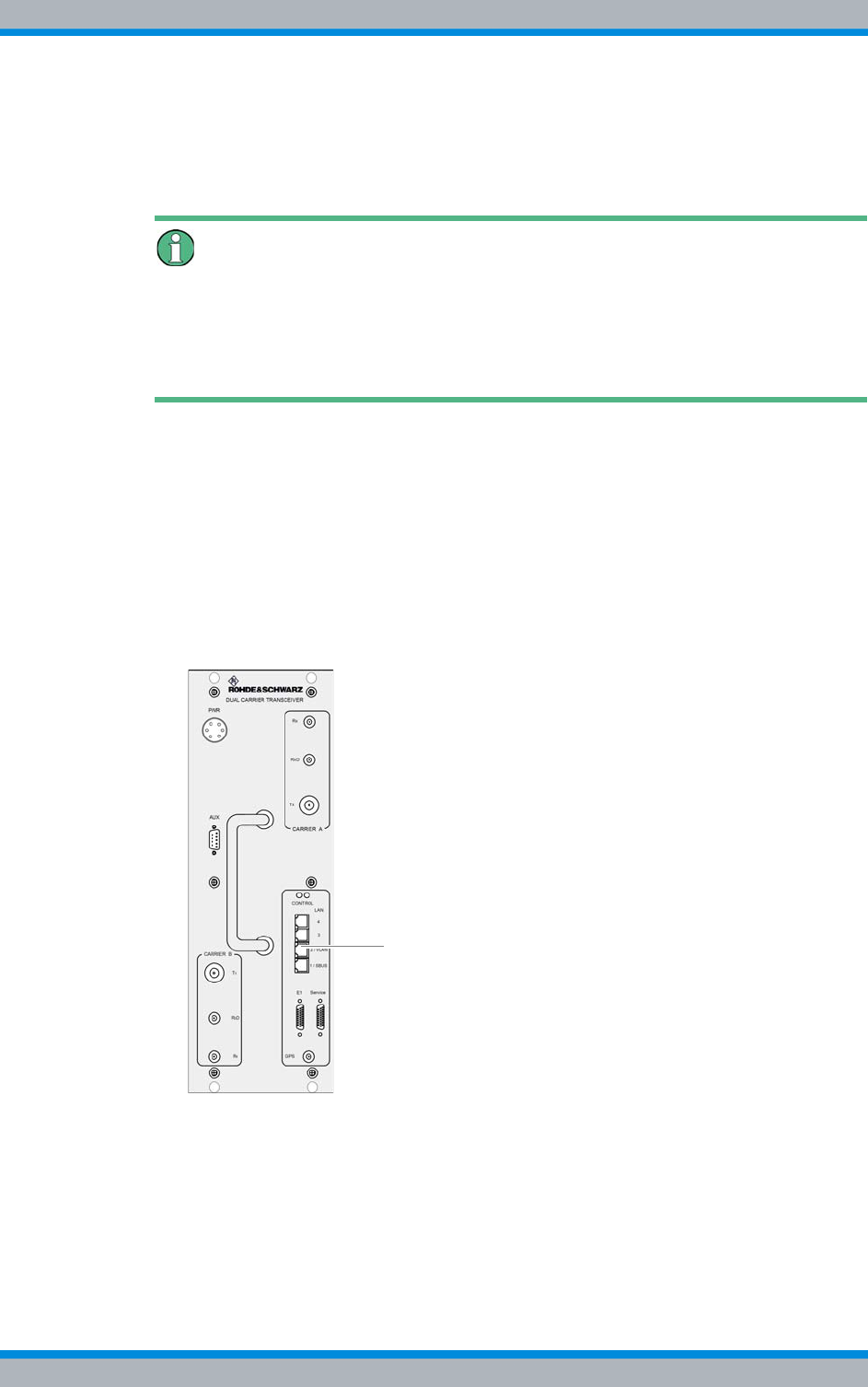
Installation, Operation and Service Manual 90DIB500R41IM_FCC02 – 99.1 133
DIB-500 R4.1 Configuration
Configuring the software
6.1.2.1 Connecting the service computer to the TIB transceiver module
In principle, the service computer can be connected to any open Ethernet interface of
the TIB transceiver module.
Connecting the service computer despite assigned Ethernet interfaces
If all Ethernet interfaces of the respective TIB transceiver module are assigned, you can
disconnect the Ethernet cable for connection to the layer-3 switch/IP transport network,
if necessary, and connect the service computer to the corresponding Ethernet interface.
Note that a connection to the IP transport network no longer exists in this case.
Proceed as follows to connect the service computer:
Preparation:
✓The working appliances must be available, refer to section 6.1.1 on page 132.
✓The service computer must have been started already.
✓The corresponding On/Of switch(es) must be in the "On" position (switch position:
"Up").
Carry out the following steps:
➔Connect the Ethernet cable to the service connector of the network element (refer
to Figure 6.1) and to the Ethernet port of the service computer.
Figure 6.1 Service connector
✓You have successfully connected the service computer.

DIB-500 R4.1 Configuration
Configuring the software
134 Installation, Operation and Service Manual 90DIB500R41IM_FCC02 – 99.1
6.1.3 Deleting the ARP buffer
The assignments of IP addresses to hardware addresses of network adapters (MAC
address) are stored in the ARP (Address Resolution Protocol) buffer.
To ensure the proper execution of the initial download and to be able to directly connect
with hardware components, it is necessary to delete the ARP buffer on the respective
service computer after every connection.
Proceed as follows to delete the ARP buffer:
Preparation:
✓The service computer must be connected.
Carry out the following steps:
1. Call up the command prompt via the Windows Start menu > Programs > Accesso-
ries > Command Prompt.
➥The "command prompt" is displayed:
2. Enter the command below to delete the ARP buffer:
arp -d
3. If necessary, you can use the following command to display entries in the ARP
buffer:
arp -a
✓You have successfully deleted the ARP buffer.
6.1.4 Configuring and generating network configurations via the
NMC-515 ConfigurationManager
Via the NMC-515 ConfigurationManager network management client, the network con-
figuration for an ACCESSNET®-T IP network is created based on the defined network
design. For this purpose, the NMC-515 ConfigurationManager permits the creation and
adaptation of an ACCESSNET®-T IP network model. The calculations of the required
configurations for the operating systems and software components used and the gener-
ation of the configuration files are based on this network model.
The procedures for generating network configurations via the NMC-515 Configuation-
Manager network management client are described in the related product documents,
refer to Table 6.5.
Table 6.5 Required product documents
Product Document type Described in
NMC-515 ConfigurationManager User Manual Chapter 4
Installation, Operation and Service Manual 90DIB500R41IM_FCC02 – 99.1 135
DIB-500 R4.1 Configuration
Configuring the software
6.1.5 Creating the download repository
For commissioning network elements locally via the NMC-522 DownloadManager, the
Download Repository must be created on the service computer. For this purpose, the
required directory structures must be stored on the service computer.
The procedures for this purpose are described in corresponding documents, refer to
Table 6.6.
6.1.6 Adapting IP addresses (with more than one transceiver module)
If a base station with multiple transceiver modules is used, the IP addresses of these
hardware components must be adapted.
The following work steps are required for this purpose:
|Adapting the IP addresses (IntelPC)
|Adapting the IP addresses (PowerPC)
6.1.6.1 Adapting the IP addresses (IntelPC)
The IP addresses of the hardware components are identical after the respective plat-
form image has been loaded. When hardware components are delivered, the platform
images have already been loaded. For the initial download via the NMC-522 Download-
Manager, however, the corresponding hardware components must feature a unique IP
address.
Table 6.7 describes the standard IP address that is assigned while loading the platform
image of a transceiver module.
If a base station with multiple transceiver modules is used, the IP addresses of all addi-
tional transceiver modules must be adapted. Otherwise it will not be possible to access
the respective transceiver module(s).
Table 6.8 describes the IP scheme by which the IP addresses of the transceiver mod-
ules must be assigned.
Table 6.6 Required product documents
Product Document type
Service computer Configuration Manual
Table 6.7 Standard IP addresses of the transceiver modules
Standard IP address
10.255.255.1
Table 6.8 Transceiver module IP addressing scheme (IntelPC)
First
transceiver module
Second
transceiver module
Third
transceiver module
Fourth
transceiver module
10.255.255.1 10.255.255.2 10.255.255.3 10.255.255.4
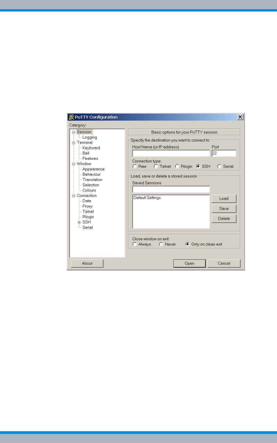
DIB-500 R4.1 Configuration
Configuring the software
136 Installation, Operation and Service Manual 90DIB500R41IM_FCC02 – 99.1
Adapting the IP address
Preparation:
✓According to the configured service computer, refer to the Configuration Manual
"Service Computer for ACCESSNET®-T IP"
✓The service computer must be connected to the corresponding component, see
section 6.1.2.1 on page 133.
Carry out the following steps:
1. Start "PuTTY" by double-clicking the executable file.
➥The user interface of "PuTTY" will be displayed:
Figure 6.2 "PuTTY" user interface
2. Enter the corresponding standard IP address in the Host Name (or IP address)
field, see Table 6.7 on page 135.
3. Click Open.
➥The SSH connection will be established.
➥The following output is displayed:
login as:
4. Enter the following as the user name:
root
5. Press the ENTER key to confirm your input.
6. Enter the following as the password:
accessnet
7. Press the ENTER key to confirm your input.
➥The connection to the component has been set up.

Installation, Operation and Service Manual 90DIB500R41IM_FCC02 – 99.1 137
DIB-500 R4.1 Configuration
Configuring the software
Command "ifconfig.xxx"
The "ifconfig.xxx" command opens the corresponding "ethX/Y" configuration file. "xxx"
corresponds to the respective configuration file. The "ethX/Y" configuration files depend
on the component. Thus, the commands listed below are possible:
|MPU-550 and TIB/TOB (DIB-500 R3.2 and DIB-500 R4)
– eth1/1 contains the IP address for the initial download. This file must be config-
ured accordingly.
– eth1/0 receives the customer-specific IP address for operation with the initial
download.
|GPP-100 and TIB (DIB-500 R4.1)
– eth0/0 receives the customer-specific IP address for operation with the initial
download.
– eth0/1 contains the IP address for the initial download. This file must be config-
ured accordingly.
8. Enter the following command to open the corresponding configuration file:
vi /etc/sysconfig/network/devices/ifconfig.xxx
"xxx" corresponds to the command for the corresponding component.
➥The "ethX/Y" configuration file will open. The following output is an example:
# ====================================================
# ACCESSNET-T Configuration File
#
# Network : cta
# Description : CTA_CFG_TL47_5_v04
# Config. Int. Version : 1.3
# Network Element : bs02-001
# Network Component : IntelPC_1
# Configuration version : 0.0
# Generated by : NMC-515 ConfigurationManager 2.32.7
# Date/Time : 2008-02-22 16:45:19
# =====================================================
ONBOOT=YES
SERVICE=ipv4-static
IP=10.255.25x.xxx
PREFIX=27
Different configuration files
Depending on the component/s, multiple "ethX/Y" configuration files may be available.
The configuration file must match the corresponding component.
➔Check the contents of the open configuration file. The "IP" entry must match the cor-
responding component, refer to 6.1.4 on page 134.
9. In the "IP“ entry, navigate to the passage to be adapted with the arrow keys.

DIB-500 R4.1 Configuration
Configuring the software
138 Installation, Operation and Service Manual 90DIB500R41IM_FCC02 – 99.1
10. Enter the following command to delete the corresponding line:
x
11. Enter the following command to insert a corresponding figure:
I
12. Navigate to the end of the line with the arrow keys and enter the corresponding fig-
ure, see 135.
13. Enter the following command to change to the main menu:
Esc
14. Enter the following command and confirm your entry with the Enter key:
:wq
➥The changes will be saved and the configuration file closed.
15. Enter the following command to restart the network service of the component:
/etc/init.d/network restart
➥The changed IP address will take effect.
➥The SSH connection via "PuTTY" will be changed because the IP address has
changed.
Checking the IP address – (optionally)
If required, check the IP address by establishing an SSH connection via PuTTY. You
can also check whether the IP address can be reached by entering the command ping
10.255.25x.xxx. 255.25x.xxx corresponds to the respective IP address.
16. If required, proceed analogously for any further IP addresses.
✓The procedure for adapting the IP address has been completed.
6.1.6.2 Adapting the IP addresses (PowerPC)
For the proper operation of the PowerPC, the IP address/es of the PowerPC must be
adapted after the IP address of the IntelPC (refer to section 6.1.6.1 on page 135) has
been adapted.
Table 6.9 describes the IP addressing scheme, according to which the IP addresses of
the PowerPCs of the transceiver modules of base stations are to be assigned.
The procedure for adapting the IP address is described in the following.
Table 6.9 Transceiver module IP addressing scheme (PowerPC)
First
transceiver module
Second
transceiver module
Third
transceiver module
Fourth
transceiver module
10.255.255.17 10.255.255.18 10.255.255.19 10.255.255.20
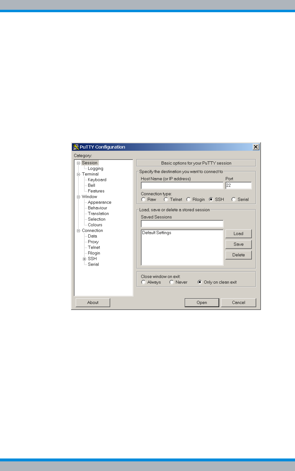
Installation, Operation and Service Manual 90DIB500R41IM_FCC02 – 99.1 139
DIB-500 R4.1 Configuration
Configuring the software
Adapting the IP address
Preparation:
✓According to the configured service computer, refer to the Configuration Manual
"Service Computer for ACCESSNET®-T IP"
✓The service computer must be connected to the corresponding component, see
section 6.1.2.1 on page 133.
✓The IP address of the IntelPC must have been adapted already.
✓The ARP buffer of the service computer must be deleted again, see section 6.1.3
on page 134.
Carry out the following steps:
1. Start "PuTTY" by double-clicking the executable file.
➥The user interface of "PuTTY" will be displayed:
Figure 6.3 "PuTTY" user interface
2. Enter the corresponding IP address in the "Host Name (or IP address)" field, refer
to Table 6.8 on page 135.
3. Click "Open".
➥The SSH connection will be established.
➥The following output is displayed:
login as:
4. Enter the following as the user name:
root
5. Press the ENTER key to confirm your input.
6. Enter the following as the password:
accessnet
7. Press the ENTER key to confirm your input.
➥The connection to the component has been set up.

DIB-500 R4.1 Configuration
Configuring the software
140 Installation, Operation and Service Manual 90DIB500R41IM_FCC02 – 99.1
8. Enter the following command to open the corresponding configuration file:
vi /etc/udhcpd.conf
➥The "udhcpd.conf" configuration file is opened. The following output is an exam-
ple:
# ================================================================
# ACCESSNET-T Configuration File
#
# Network : cta
# Description : cta
# Package Version : 7.0
# Network Element : bs01-002 (DIB1_12)
# Software Component : aeos-intel_1 (AEOS Intel)
# Software Version :
# Configuration Version : 1001281502
# Generated by : NMC-515 ConfigurationManager 03.01.00
# Date/Time : 28.01.2010 15:02:32 CET
# ================================================================
start 10.101.101.49
end 10.101.101.49
interface eth1
siaddr 10.101.101.33
option lease 864000
option subnet 255.255.255.224
max_leases 1
dhcp_magkey 0x13242c8
opt bootfile autoscript.img
9. Navigate to the IP address of the "start" entry with the arrow keys.
10. Enter the following command to delete the corresponding line:
x
11. Enter the following command to insert a corresponding figure:
I
12. Enter the corresponding IP address of the PowerPC, refer to Table 6.9 on
page 138.
The IP addresses in the "start" and "end" entries must be identical. Otherwise the
proper operation of the PowerPC is not ensured.
➔Ensure that the IP addresses in the "start" and "end" entries are identical.
13. Proceed analogously for the IP address of the "end" entry.
14. Navigate to the IP address of the "siaddr" entry with the arrow keys.
15. Enter the following command to delete the corresponding line:
x
16. Enter the following command to insert a corresponding figure:
I

Installation, Operation and Service Manual 90DIB500R41IM_FCC02 – 99.1 141
DIB-500 R4.1 Configuration
Configuring the software
17. Enter the corresponding IP address of the IntelPC, refer to Table 6.8 on page 135.
18. Enter the following command to change to the main menu:
Esc
19. Enter the following command and confirm your entry with the Enter key:
:wq
➥The changes will be saved and the configuration file closed.
20. Enter the following command to open the corresponding configuration file:
vi /etc/exports
➥The "exports" configuration file is opened. The following output is an example:
# ================================================================
# ACCESSNET-T Configuration File
#
# Network : cta
# Description : cta
# Package Version : 7.0
# Network Element : bs01-002 (DIB1_12)
# Software Component : aeos-intel_1 (AEOS Intel)
# Software Version :
# Configuration Version : 1001281502
# Generated by : NMC-515 ConfigurationManager 03.01.00
# Date/Time : 28.01.2010 15:02:32 CET
# ================================================================
/ 10.101.101.49/
255.255.255.224(rw,no_root_squash,no_subtree_check)
/linuxppc 10.101.101.49/
255.255.255.224(rw,no_root_squash,no_subtree_check)
intelpc-1-1-1-1-bs01-002:~ #
Adaptation of the network mask not required
The network mask need not be adapted (here "255.255.255.224").
21. Navigate to the IP address of the "/" (here: "10.101.101.49") entry with the arrow
keys.
22. Enter the following command to delete the corresponding line:
x
23. Enter the following command to insert a corresponding figure:
I
24. Enter the corresponding IP address of the PowerPC, refer to Table 6.9 on
page 138.
25. Proceed analogously for the IP address of the "/linuxppc" entry.
26. Enter the following command to change to the main menu:
Esc (Escape)
27. Type in the following command:

DIB-500 R4.1 Configuration
Configuring the software
142 Installation, Operation and Service Manual 90DIB500R41IM_FCC02 – 99.1
:wq
28. Press the ENTER key to confirm your input.
➥The changes will be saved and the configuration file closed.
29. Enter the following command to restart the hardware component:
reboot
➥The hardware component is restarted.
Checking the IP addresses (optionally)
If required, check the IP address by establishing an SSH connection via PuTTY. Alter-
natively you can check the availability of the IP addresses of the IntelPC and PowerPC
via the command ping 10.255.25x.xxx. 255.25x.xxx corresponds to the respective
IP address, refer to Table 6.8 and Table 6.9.
✓The procedure for adapting the IP address has been completed.
6.1.7 Performing an initial download via NMC-522 DownloadManager
The NMC-522 DownloadManager network management client transmits the required
data from the download repository to the network elements via an initial download. The
initial download can only be performed on site via the service computer. For the initial
download, a direct Ethernet connection between service computer and the first TIB
transceiver module is required.
Deleting the ARP buffer
To ensure that the initial download is performed properly, the ARP buffer must be
deleted after the service computer has been connected, refer to section 6.1.3 on
page 134.
The procedures for operating the NMC-522 DownloadManager network management
client are described in the related product documents, refer to Table 6.10.
Table 6.10 Required product documents
Product Document type Described in
NMC-522 DownloadManager User Manual Chapter 4
Installation, Operation and Service Manual 90DIB500R41IM_FCC02 – 99.1 143
DIB-500 R4.1 Configuration
Adjusting a cavity coupler – optional (cavity variant only)
6.2 Adjusting a cavity coupler – optional (cavity variant
only)
The cavity coupler must be matched to the set Tx frequency of the connected carrier. To
be able to perform this setting, only the carrier to be measured in each case is activated
to exclusively measure its power at the antenna output. The Tx frequency is adjusted
with the handwheel of the corresponding cavity coupler so that the maximum transmit-
ting power is present at the antenna connection.
Damage to circulators
When new frequencies are configured via the NMC-515 network management client,
the circulators may be damaged if the cavity coupler(s) is/are not adjusted to these fre-
quencies.
➔Configure a maximum transmitter output of 1,000 mW via the NMC-515 Configura-
tionManager for the corresponding carrier(s) using the carrier item. This corre-
sponds to a value of 30 dBm.
➔Adjust the cavity coupler(s) as soon as possible to the corresponding frequencies.
The cavity coupler(s) must be adjusted manually.
Procedure described refers to one cavity coupler
The procedure described in the following refers to one cavity coupler. Depending on the
DIB-500 R4.1 variant, the work steps may have to be repeated for further cavity cou-
plers.
The tasks listed in the following table must be performed for the adjustment of a cavity
coupler.
Table 6.11 Overview of the tasks to be performed (Adjusting a cavity coupler – optional (cavity vari-
ant only))
Tasks/work steps Described in
Connecting the service computer to the TIB transceiver module Section 6.1.2.1
on page 133
Setting the output rating Section 6.2.2 on
page 144
Measuring and checking the carriers (impedance adjustment) Section 6.2.3 on
page 146

DIB-500 R4.1 Configuration
Adjusting a cavity coupler – optional (cavity variant only)
144 Installation, Operation and Service Manual 90DIB500R41IM_FCC02 – 99.1
6.2.1 Tools and aids
Table 6.12 provides an overview of tools and aids that are required for adjusting a cavity
coupler.
6.2.2 Setting the output rating
To adjust the cavity coupler to a new Tx frequency, a sufficiently high output power must
be set so that changes at the handwheel of the cavity coupler are detectable at the
measuring device.
Proceed as follows to set the output power to a standard value:
Preparation:
✓The tools and aids must be available, refer to section 6.2.1 on page 144.
✓The current transmission power and frequency must be known.
✓The On/Off switches must be set to switch position "On" (switch position: up), see
Figure 3.15 on page 43.
✓The service computer must be connected via Ethernet cable, see section 6.1.2.1
on page 133.
✓The service computer must have been started.
Carry out the following steps:
1. Call up the command prompts via the Windows menu Start > Run.
2. Enter the command cmd .
➥The command prompt window opens.
3. Initiate a TELNET session to the BSC command shell by entering the command
telnet 10.xxx.xxx.XX 5100 to query the frequency of all active carriers.
xxx corresponds to the IP address of the BSC (PUC) depending on the site, refer to
the project-specific documents.
XX corresponds to the IP address of the PowerPC of the corresponding TIB.
4. After the command prompt, enter u S3 to change to user level 3.
5. Enter the command p 1 -A sbue sbcc 02 0x to check the configured output
power of the corresponding carrier;
x corresponds to carrier no.
➥The power of the corresponding carrier is displayed in mW:
Table 6.12 Overview of tools and aids (Adjusting a cavity coupler – optional (cavity variant only))
Work step Tools, aids
Setting a cavity coupler
to the TX frequency |A service computer that is configured accordingly1)
|Straight through ethernet cable
|VSWR measuring instrument, recommended:
– R&S NRT measuring device and the appropriate adapter
– NRT-Z44 measuring head and the appropriate adapter
|RF connecting cable for connection with the VSWR measuring
instrument
|Dummy load (50 Ω)
|Screwdriver/wrench to loosen the fastening screw of the cavity
coupler (for frequencies ≥ 800 MHz)
1) see the "Service computers for ACCESSNET®-T IP" configuration manual

Installation, Operation and Service Manual 90DIB500R41IM_FCC02 – 99.1 145
DIB-500 R4.1 Configuration
Adjusting a cavity coupler – optional (cavity variant only)
BSC Command Shell tobs-ppc (Port: 5100)
u
'puc_1'-BSC 10.32.36.17 (5100) >u **
Password OK
User Level: 3
Command is okay
p l -A sbue sbcc 02 01
'puc_1'-BSC 10.32.36.17(5100)>pl-A sbue sbcc 02 01
Appl Node No In Description Parameter value R
------------------------------------------------------SBUE SBCC 02
01 Transmit power of the carrier in mW 600
Command is okay
6. Repeat this work step for all the carriers that have to be set accordingly.
7. Enter the p s sbue sbcc 02 0x 25000 command to set the output power to
25 W;
x corresponds to the carrier number.
➥The following output is displayed:
'puc_1'-BSC 10.32.36.17 (5100) >p s sbue sbcc 02 01 25000
SBUE SBCC 02 01 Transmit power of the carrier in mW 25000
Command is okay
8. Repeat this work step for all the carriers that have to be set accordingly.
9. Enter the car hw-reset x,
x corresponds to carrier no.
➥The following output is displayed:
'puc_1'-BSC 10.32.36.17 (5100) >
car hw-reset 1
'puc_1'-BSC 10.32.36.17 (5100) >car hw-reset 1
Command is okay
10. Use the command bsca la to check whether the corresponding carriers have
actually been reactivated.
➥The following output is displayed:
bsca la
'puc_1'-BSC 10.32.36.17 (5100) >bsca la
Active Alarms of component BSC:
--------------------------------
none
Active Alarms of component CAR1:
--------------------------------
none
Active Alarms of component CAR2:
--------------------------------
none
Command is okay

DIB-500 R4.1 Configuration
Adjusting a cavity coupler – optional (cavity variant only)
146 Installation, Operation and Service Manual 90DIB500R41IM_FCC02 – 99.1
Take note of the status
A carrier is enabled when the output for the corresponding carrier shows none . If the
carrier has not been enabled, you have to repeat the command..
✓You have successfully set the output power.
6.2.3 Measuring and checking the carriers (impedance adjustment)
For all the variants of the DIB-500 R4.1 the same procedure is used for measuring and
checking carriers (impedance adjustment). Depending on the variant, the hand wheel of
the cavity combiner is secured with a mounting screw.
Overheating of the Tx insulator
The Tx insulator of the respective cavity coupler can overheat during the impedance
adjustment.
➔Close the impedance adjustment within 10 minutes.
➔As an alternative, you can interrupt the process and wait until the Tx insulator has
cooled off.
Additional work steps (depending on the variant)
Depending on the variant, the mounting screw of the hand wheel may have to be loos-
ened/tightened using a screwdriver/spanner before/after adjusting the cavity combiner.
Measuring instrument used
The procedure for impedance adjustment described below applies exclusively to the
use of the recommended R&S NRT VSWR measuring equipment (incl. NRT-Z44 meas-
uring equipment). If impedance adjustment was performed with a different measuring
instrument, always proceed in keeping with the product documentation of the measur-
ing instrument used.
Measuring and checking carriers (impedance adjustment)
Preparation:
✓The tools and aids must be available, refer to section 6.2.1 on page 144.
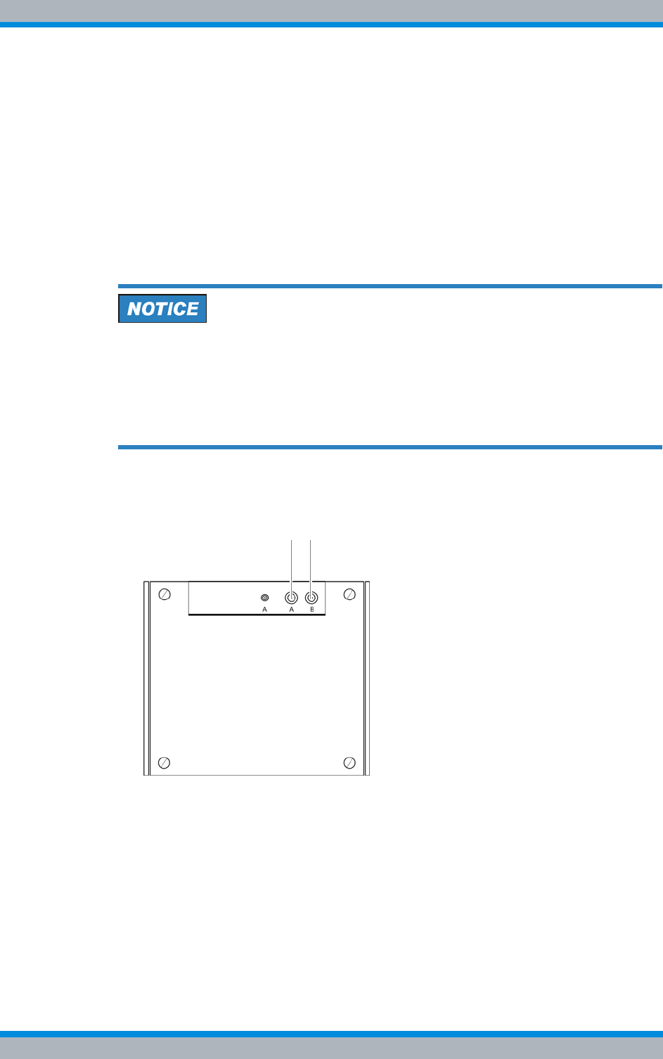
Installation, Operation and Service Manual 90DIB500R41IM_FCC02 – 99.1 147
DIB-500 R4.1 Configuration
Adjusting a cavity coupler – optional (cavity variant only)
Carry out the following steps:
1. Disable all the corresponding carriers with the command car shutdown x;x cor-
responds to carrier no.
➥The following output is displayed:
car shutdown 1'puc_1'-BSC 10.xx.xx.XX (5100) >car shutdown
1Command is okay
2. Use the command bsca la to verify whether the corresponding carriers are actu-
ally disabled.
➥A carrier is disabled when the output for the corresponding carrier yields
CAR_DOWN_EVP. If the carrier has not been disabled yet, you have to repeat
the corresponding command.
If neither an antenna is mounted nor a dummy load is applied when the antenna
cable is removed, an overload may occur due to the missing terminating resist-
ance . The components fitted could then be damaged.
➔Ensure that the original antenna is connected to the antenna connector above the
equipment cabinet, refer to Figure 6.4.
➔Otherwise, fit a dummy load (50 Ω) to the antenna connection.
3. Remove the antenna cable from the corresponding antenna connector, refer to Fig-
ure 6.4.
Figure 6.4 Antenna connectors
4. Plug the connecting cable of the respective measuring probe including the adapter
into the free antenna connector, refer to Figure 6.5.
A B
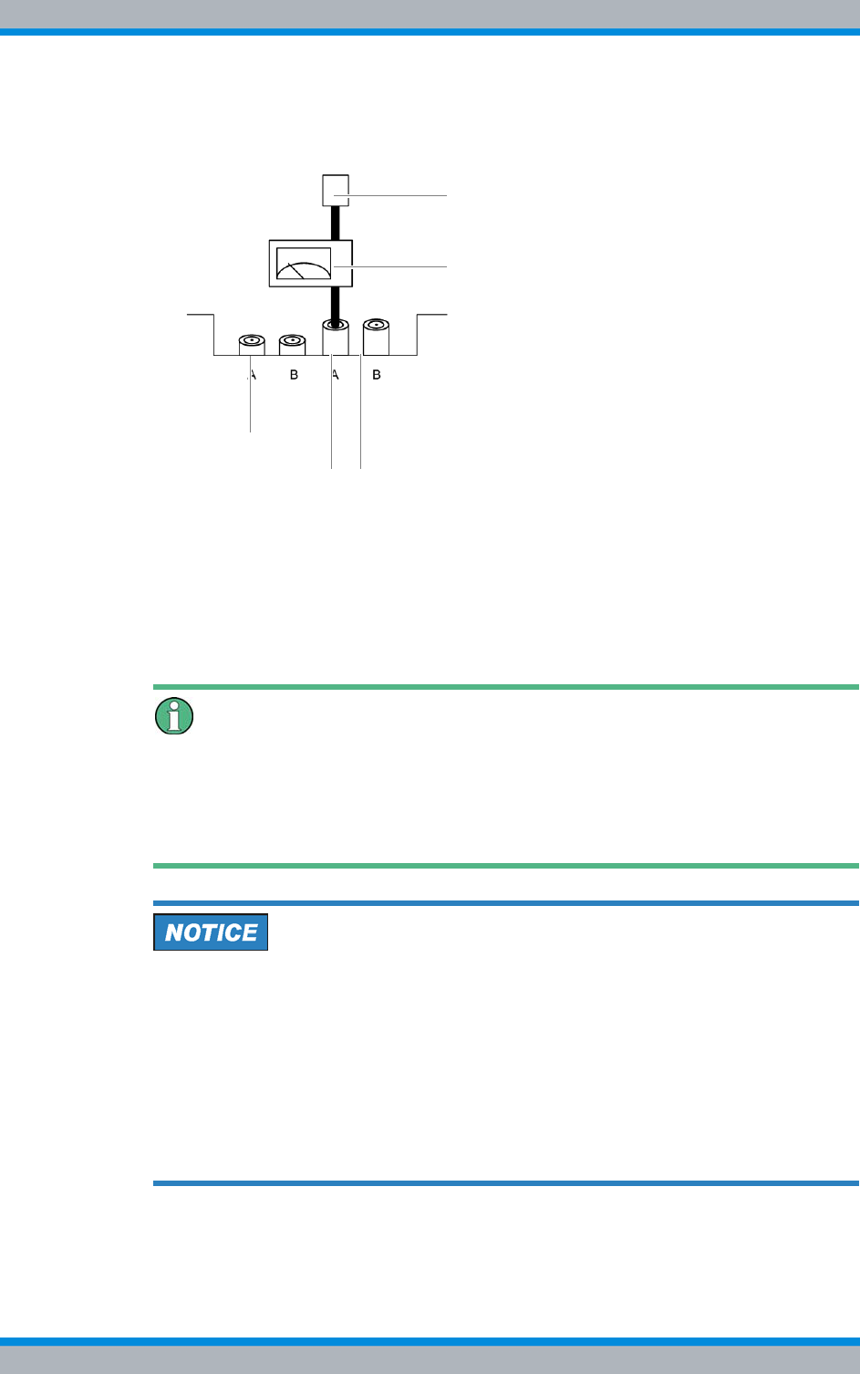
DIB-500 R4.1 Configuration
Adjusting a cavity coupler – optional (cavity variant only)
148 Installation, Operation and Service Manual 90DIB500R41IM_FCC02 – 99.1
5. Connect the antenna cable to the adapter of the measuring probe. Alternatively,
connect a dummy load (50 Ω), refer to Figure 6.5.
Figure 6.5 Connected measuring equipment
6. Switch on the appropriate measuring equipment and check the AVG (W) and SWR
of the R&S NRT measuring equipment on the display.
7. Enable the carrier to be measured with the command car sw-reset x, x corre-
sponds to carrier no.
➥The set power is displayed:RF output power on the R&S NRT (display [AVG]).
8. Release the hand wheel on the front of the corresponding cavity coupler.
Adjusting the maximum transmitter output
The handwheel must be adjusted so that the maximum transmitting power is achieved.
When turning the handwheel, the transmitting power climbs to a maximum value and
then drops back down with continued turning. If this happens, turn the cavity coupler
handwheel back in the opposite direction in order to reset the maximum value.
Damage to circulators
When new frequencies are configured via the NMC-515 network management client,
the circulators may be damaged if the cavity coupler(s) is/are not adjusted to these fre-
quencies.
➔Configure a maximum transmitter output of 1,000 mW via the NMC-515 Configura-
tionManager for the corresponding carrier(s) using the carrier item. This corre-
sponds to a value of 30 dBm.
➔Adjust the cavity coupler(s) as soon as possible to the corresponding frequencies.
The cavity coupler(s) must be adjusted manually.
9. Use the cavity coupler handwheel to adjust the Tx frequency until the maximum
transmitter output is present at the antenna connection.
Measuring equipment
GPS
Antenna connectors
Antennna cable/dummy load

Installation, Operation and Service Manual 90DIB500R41IM_FCC02 – 99.1 149
DIB-500 R4.1 Configuration
Adjusting a cavity coupler – optional (cavity variant only)
Maximum transmitter output measurement
The maximum transmitter output measurement must always be greater than the value
produced by the following formula: Maximum transmitter output configuration - 5 dBm.
10. Tighten the handwheel on the front of the corresponding cavity coupler again.
11. Disable the measured carrier again with the command car shutdown x,
x corresponds to carrier no.
12. Repeat the previous work steps beginning with step 7. for all the carries to be
measured.
13. Remove the antenna cable or the dummy load from the adapter of the measuring
probe.
14. Remove the corresponding measuring equipment and reconnect the antenna
cable.
15. Set the output power back to the permissible value (network-specific) with the com-
mand p s sbue sbcc 02 0x XXXXX;
x corresponds to carrier no.;
XXXXX corresponds to the power in W. For information on the permissible value,
please refer to the project-specific documents.
16. Re-enable all the carriers with the command car sw-reset x,
x corresponds to carrier no.
17. Use the command bsca lato check whether the corresponding carriers have
actually been reactivated.
➥The following output is displayed:
bsca la'puc_1'-BSC 10.32.35.17 (5100) >bsca laActive Alarms of
component BSC:---------------------------------
noneActive Alarms of component CAR1:------------------
--------------- noneActive Alarms of component CAR2:--
------------------------------- noneCommand is okay
Take note of the status
A carrier is enabled when the output for the corresponding carrier shows none. If the
carrier has not been enabled, you have to repeat the command.
✓The impedance adjustment has been completed.

DIB-500 R4.1 Configuration
Concluding tasks
150 Installation, Operation and Service Manual 90DIB500R41IM_FCC02 – 99.1
6.3 Concluding tasks
Once you have successfully completed the visual inspection via the SMT, you must
restore the proper operational state of the product.
Proceed as follows to restore the operating condition
Preparation:
✓The network element must have been put out of operation temporarily, refer to sec-
tion 8.1 on page 163.
✓The tools, auxiliary means and materials specified must be available, refer to
section 6.1.1 on page 132.
Carry out the following steps:
1. Reconnect the connecting cables to the RJ-45 or LSA+ terminal block on the E1
connection board.
2. If necessary, reattach the Ethernet cables that are intended for the connection to
the Ethernet interfaces of the TIB transceiver module.
3. If necessary, reinstall the covers of the equipment rack.
4. Put the network element into operation again, refer to section 9.1 on page 167.
✓You have restored the proper operating condition of the product.

Installation, Operation and Service Manual 90DIB500R41IM_FCC02 – 99.1 151
DIB-500 R4.1 Function tests and operating surveillance
7 Function tests and operating surveillance
After all the tasks have been performed on the product that have effects on the product
and/or its components, the proper operation of all the integrated network and hardware
components should be tested. We recommend logging the results of the test.
In addition, it is recommended to perform the tasks described in the following sections in
regular intervals during the operation.
Table 7.1 provides an overview of tasks for testing the function and for operational mon-
itoring.
Table 7.1 Overview of tasks (Function tests and operating surveillance)
Tasks/work steps Described in
Checking operating states Checking operating statuses via the NMC-511 FaultManager Section 7.2.1 on
page 153
Checking operating statuses via LEDs of the TIB Section 7.2.2 on
page 153
Checking operating statuses via LEDs of the SC200 or rectifier
modules – optional (only for VAC voltage supply) Section 7.2.3 on
page 154
Checking operating states via SMT-500 Section 7.2.4 on
page 155
Checking the reachability of network elements Section 7.3 on
page 155
Checking voice channels Checking the voice channel (two carriers) Section 7.4.1 on
page 156
Checking the voice channel (more than two carriers) Section 7.4.2 on
page 157
Checking standby carriers – optional Section 7.5 on
page 158
Function tests and operat-
ing surveillance GPS Checking the installation site of the GPS antenna Section 7.6.1 on
page 159
GPS operational monitoring (via NMC-511 FaultManager) Section 7.6.2 on
page 159
Function tests and fault analysis GPS Section 7.6.3 on
page 161
Checking external antenna coupling systems Section 7.7 on
page 162

DIB-500 R4.1 Function tests and operating surveillance
Work equipment for function tests
152 Installation, Operation and Service Manual 90DIB500R41IM_FCC02 – 99.1
7.1 Work equipment for function tests
Table 7.2 provides an overview of the work equipment required for the steps in this
chapter.
7.2 Checking operating states
The proper operation of the product and the integrated hardware components can be
tested manually – provided indicators are available – at the respective hardware com-
ponent or via a connected NMC-511 FaultManager network management client.
In addition, the operating statuses can be checked via the SMT (Service and Mainte-
nance Tool) hardware component.
Table 7.3 provides an overview of the procedures for checking operating states of the
DIB-500 R4.1.
Table 7.2 Overview of work equipment (function tests and operating surveillance)
Work step Work equipment
Checking operating statuses via the
NMC-511 FaultManager |according to the configured service computer, refer
to the Configuration Manual "Service Computer for
ACCESSNET®-T IP"
|Straight through ethernet cable
|Network management client NMC-511 FaultMan-
ager
Checking voice channels |according to the configured service computer, refer
to the Configuration Manual "Service Computer for
ACCESSNET®-T IP"
|min. two mobile stations
Checking the reachability of net-
work elements |according to the configured service computer, refer
to the Configuration Manual "Service Computer for
ACCESSNET®-T IP"
|Straight through ethernet cable
Function tests and operating sur-
veillance GPS |Network management client NMC-511 FaultMan-
ager
|GPS antenna
|GPS antenna cable
|GPS protector
Table 7.3 Overview of the procedures for checking operating states
Work step Described in
Checking operating statuses via the NMC-511 FaultManager Section 7.2.1 on
page 153
Checking operating statuses via LEDs of the TIB Section 7.2.2 on
page 153
Checking operating statuses via LEDs of the SC200 or rectifier mod-
ules – optional (only for VAC voltage supply) Section 7.2.3 on
page 154
Checking operating states via SMT-500 Section 7.2.4 on
page 155

Installation, Operation and Service Manual 90DIB500R41IM_FCC02 – 99.1 153
DIB-500 R4.1 Function tests and operating surveillance
Checking operating states
7.2.1 Checking operating statuses via the NMC-511 FaultManager
To check the operating states via the NMC-511 FaultManager, a service computer that
is configured accordingly or an NMC computer with installed NMC-511 FaultManager is
required which is connected via remote operation using a Remote Desktop connection
with the ACCESSNET®-T IP network.
Checking the operating status (via the NMC-511 FaultManager)
Preparation:
✓The NMC-511 FaultManager must have been started.
Carry out the following steps:
1. Use the Equipment view of the NMC-511 FaultManager to navigate to the corre-
sponding network constituent (hardware or software component).
2. Ensure that the corresponding network constituent is shown in green in the Equip-
ment view of the NMC-511 FaultManager.
➥If the respective network constituent is shown in red, you must perform a fault
analysis, see NMC-511 FaultManager User Manual.
3. Check whether a predecessor alarm status is displayed for the respective network
constituent which displays a fault that may already have existed.
➥If the predecessor alarm status is shown in red, it is recommended to generate a
report via the Analysis perspective.
4. Navigate to the Service perspective and check whether corresponding services are
shown in green.
➥If services are shown in red, you must perform a fault analysis, see NMC-511
FaultManager User Manual.
✓The function test has been completed.
7.2.2 Checking operating statuses via LEDs of the TIB
The procedure for checking operating statuses (visual inspection) of integrated network/
hardware components is described in the following.
Check the operating states of installed network and hardware components
Preparation:
✓The electrical connection must be made and commissioning completed.
Carry out the following steps:
➔Check the operating states of installed hardware components.
➥The Power LED (1) is lit and the Alive LED (2) flashes in periodical intervals,
refer to Figure 7.1.
Figure 7.1 TIB indicators
✓The function test has been completed.
2
1
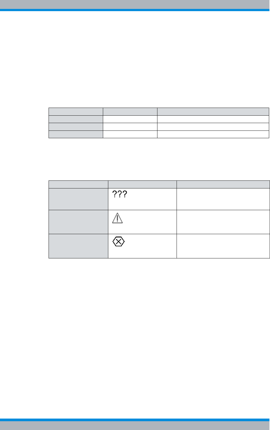
DIB-500 R4.1 Function tests and operating surveillance
Checking operating states
154 Installation, Operation and Service Manual 90DIB500R41IM_FCC02 – 99.1
7.2.3 Checking operating statuses via LEDs of the SC200 or rectifier
modules – optional (only for VAC voltage supply)
The proper operation of the voltage supply unit can be checked via the LEDs of the
SC200 and the LEDs of the rectifier modules (if available) as well as in the display win-
dow of the SC200.
Table 7.4 provides an overview of LED colours of voltage supply unit constituents and
describes them in detail.
Table 7.5 provides an overview of the possible alarm states and the corresponding
alarm indicators. The visual indicators are shown on the display window of the system
controller.
Proceed as follows to check operating statuses of the voltage supply unit:
Preparation:
✓The electrical connection must be made and commissioning completed.
Carry out the following steps:
1. Check the LEDs of the SC200 and the rectifier(s). The green LEDs must light per-
manently.
2. Check the display window of the SC200. No alarms may be displayed.
✓The function test has been completed.
Table 7.4 LED colours (voltage supply unit)
LED Colour Description
POWER Green LED for signalling of the voltage supply.
Minor Alarm Yellow LED for signalling minor alarms.
Critical/Major Alarm Red LED for signalling major and critical alarms.
Table 7.5 Alarm states and alarm indicators (system controller)
Alarm state Visual indicator Acoustic indicator
A state cannot be dis-
played ---
MINOR Acoustic signal every two seconds.
CRITICAL/MAJOR Continuous acoustic signal

Installation, Operation and Service Manual 90DIB500R41IM_FCC02 – 99.1 155
DIB-500 R4.1 Function tests and operating surveillance
Checking the reachability of network elements
7.2.4 Checking operating states via SMT-500
The SMT (Service and Maintenance Tool) is a hardware component for checking the
operating statuses of the installed transceiver modules.
The following operating statuses can be checked through the SMT:
|Readiness for operation
|Voltage supply
|Readiness for operation of software components (n)
|Temperature
|Availability of the installed carriers
The procedures for checking operating statuses are described in the corresponding
product documentation, see Table 7.6.
7.3 Checking the reachability of network elements
Table 7.7 describes the standard IP address that is assigned while loading the platform
image of a transceiver module.
After network elements have been connected with the external layer-3 switch, you have
to check whether the respective network element can be reached via the IP address of
the first transceiver module, see Table 7.7The availability of the IP address is checked
with the command ping .
Proceed as follows to check the reachability of network elements:
Preparation:
✓The service computer must be connected to the external layer-3 switch.
✓The service computer must have been started already.
Carry out the following steps:
1. Call up the command prompt with the Windows menu Start > Programs > Accesso-
ries.
➥The "command prompt" is displayed.
2. Enter the following command to check the reachability of the network element:
ping 10.255.25X.xx
"10.255.25X.xx" corresponds to the IP address of the first transceiver module within
the network element, see Table 7.7.
✓You have successfully checked the reachability.
Table 7.6 Required product documents
Product Document type
SMT-500 Operating Manual
Table 7.7 Standard IP addresses of the transceiver modules
Standard IP address
10.255.255.1

DIB-500 R4.1 Function tests and operating surveillance
Checking voice channels
156 Installation, Operation and Service Manual 90DIB500R41IM_FCC02 – 99.1
7.4 Checking voice channels
The procedure for checking voice channels depends on the available carries of the
DIB-500 R4.1.
The following work steps are required for checking voice channels:
|Checking the voice channel (two carriers)
|Checking the voice channel (more than two carriers)
7.4.1 Checking the voice channel (two carriers)
To check the functionality of the voice connections between the base station and the
connected exchanges, voice communication must be set up between two radio sets.
Voice communication is always set up on the first free voice channel of the base station.
To be able to check all the carriers on site, the voice channels of the carrier already
checked must be disabled after a check to be able to use the next carrier for the voice
communication. The voice channels are disabled on the command interface of the TOS
component of the DIB-500 R4.1. For this purpose, a Telnet connection to the compo-
nent must be established.
Checking the Voice Channel
Preparation:
✓The working appliances must be available, refer to section 7.1 on page 152.
✓The On/Off switches must be in switch position "On" (switch position: up).
✓The service computer must have been connected refer to section 6.1.2.1 on
page 133.
Carry out the following steps:
1. Enter the following command to initiate a TELNET session to the TOS component:
telnet 10.xxx.xxx.17 5000
xxx corresponds to the IP address of the TOS) depending on the site, refer to the
project-specific documents.
2. Enter the access authorization password.
3. Establish voice communication using the two radio sets.
4. Check whether both the radio sets can send and receive voice transmissions.
5. Terminate the voice communication.
6. Enter the following commands one after the other to disable the voice channels on
the second carrier of the DIB-500 R4.1:
p s lnsw slsw 10 08 00
p s lnsw slsw 10 07 00
p s lnsw slsw 10 06 00
p s lnsw slsw 10 05 00
7. Re-establish voice communication using the two radio sets.
8. Check whether both the radio sets can send and receive voice transmissions.
9. Terminate the voice communication.
10. Enter the following commands one after the other to disable the voice channels on
the first carrier of the DIB-500 R4.1:

Installation, Operation and Service Manual 90DIB500R41IM_FCC02 – 99.1 157
DIB-500 R4.1 Function tests and operating surveillance
Checking voice channels
p s lnsw slsw 10 04 00
p s lnsw slsw 10 03 00
p s lnsw slsw 10 02 00
11. Re-establish voice communication using the two radio sets.
12. Check whether both the radio sets can send and receive voice transmissions.
13. Terminate the voice communication.
14. Enter the following command to enable the voice channels that you disabled
before:
p s lnsw slsw 10 xx 17
xx corresponds to the voice channel on the respective carrier
15. Enter the following command to restart the software component:
g quit
➥The TOS component terminates the TELNET connection to the service laptop
and restarts.
✓The check of the voice channel is complete.
Variants with more than two Carriers
For a DIB-500 R4.1 with more than two carriers, the function test must be continued as
described in section 7.4.2 on page 157.
7.4.2 Checking the voice channel (more than two carriers)
Checking the voice channels of a DIB-500 R4.1 with more than two carriers requires
further work steps in addition to the procedure described in section 7.4.1 on page 156.
Checking the Voice Channel
Preparation:
✓The working appliances must be available, refer to section 7.1 on page 152.
✓The On/Off switches must be in switch position "On" (switch position: up).
✓The SMT and the service computer must have been connected, see Operating
Manual SMT-500.
Carry out the following steps:
1. Perform the work steps step 1. to step 13. in section 7.4.1 on page 156 .
2. Enter the following command to disable the fourth carrier:
bsce block 2
3. Establish voice communication using the two radio sets.
4. Check whether both the radio sets can send and receive voice transmissions.
5. Terminate the voice communication.
6. Enter the following command to disable the third carrier:
bsce block 3

DIB-500 R4.1 Function tests and operating surveillance
Checking standby carriers – optional
158 Installation, Operation and Service Manual 90DIB500R41IM_FCC02 – 99.1
7. Enter the following command to disable the fourth carrier:
bsce block 4
8. Establish voice communication using the two radio sets.
➥The voice communication setup is denied because there are no voice channels
available.
➥The functionality of the voice channels has thus been proven.
9. Re-enable the voice channels that you disabled before. To this end, enter the fol-
lowing command to restart the TOS software component:
g quit
➥The TOS software component terminates the TELNET connection to the service
laptop and restarts.
10. Establish voice communication with the two radio sets once more to complete the
procedure.
11. Check whether both mobile stations can send and receive voice transmissions.
12. Terminate the voice communication.
13. First, enter the following command to enable all the carriers previously disabled:
bsce deblock x
x corresponds to the respective carrier
✓The check of the voice channel is complete.
7.5 Checking standby carriers – optional
ACCESSNET®-T IP optionally supports the operation of the DIB-500 R4.1 with up to
two standby carriers that replace up to two carriers that have dropped out with respect
to f frequency and function.
As a preventive maintenance measure, it is recommended to check the function of the
standby carriers at regular intervals, see section 10.1 on page 169. This is done via the
Network Management Client NMC-511 FaultManager.
Checking standby carriers
Preparation:
✓The respective DIB-500 R4.1 must be in operation.
✓The NMC-511 FaultManager must have been started.
Carry out the following steps:
1. Block the corresponding operational carrier with the NMC-511 FaultManager using
the System blocking maintenance function.
➥The corresponding carrier(s) are excluded from operational mode and identified
in the Equipment view with the "Hammer" icon.
➥Existing standby carriers are disabled.
2. In the NMC-511 FaultManager, check whether the standby carrier(s) are disabled
in the Equipment view and are not reporting any alarm.
Table 7.8 Required product documents
Product Document type Described in
NMC-511 FaultManager User Manual Chapter 4

Installation, Operation and Service Manual 90DIB500R41IM_FCC02 – 99.1 159
DIB-500 R4.1 Function tests and operating surveillance
Function tests and operating surveillance GPS
3. Unblock any blocked operational carriers after at least 5 minutes with the System
release maintenance function.
➥The system blocking of operational carriers has been revoked.
➥Standby carriers are switched back to their original status.
✓You have successfully checked the standby carriers.
7.6 Function tests and operating surveillance GPS
The following sections describe procedures for function tests and the operational moni-
toring concerning the GPS functionality of the DIB-500 R4.1.
7.6.1 Checking the installation site of the GPS antenna
To prevent damage caused by insufficient guarding and/or fastening, the installation site
of the GPS antenna should be checked following the installation of the GPS antenna.
Proceed as follows to check the installation site of the GPS antenna
Preparation:
✓The installation and connection of the GPS antenna must have been completed.
Carry out the following steps:
1. Check the installation site of the GPS for proper condition such as the fastening of
the antenna mast.
Circumferential range of vision (angle of unobstructed visibility of the sky) of the
GPS antenna.
A good circumferential range of vision (angle of unobstructed visibility of the sky accord-
ing to the recommendations of the manufacturer) must be maintained to ensure proper
reception of the GPS antenna. The angle of the GPS antenna supplied is 90 °. When
using a third-party GPS antenna, heed the corresponding documentation supplied with
the GPS antenna.
2. Check the circumferential range of vision of the GPS antenna.
✓The visual inspection has thus been completed.
7.6.2 GPS operational monitoring (via NMC-511 FaultManager)
The PUC software component (Processing Unit Controller) monitors the operation of
the GPS module. The PUC monitors the function of the GPS receiver and the visible
GPS satellites based on the received GPS data.
The NMC-511 FaultManager network management client is convenient for rapidly
detecting and localizing faults in an ACCESSNET®-T IP network. This facilitates prompt
fault elimination.
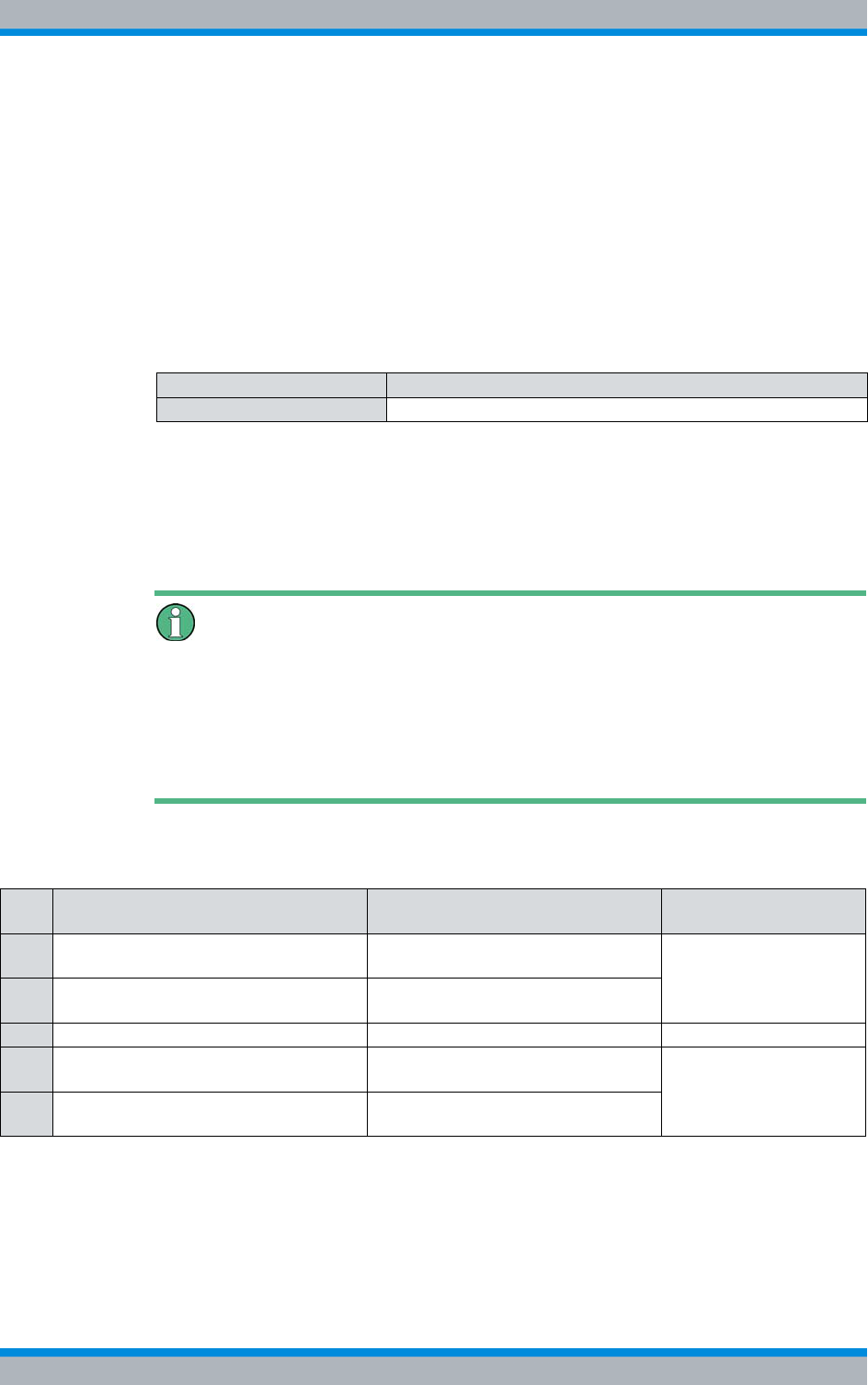
DIB-500 R4.1 Function tests and operating surveillance
Function tests and operating surveillance GPS
160 Installation, Operation and Service Manual 90DIB500R41IM_FCC02 – 99.1
All the network constituents of an ACCESSNET®-T IP network are monitored via the
NMC-511 FaultManager. Operational states and faults are detected by the network
management system and visualized via all the connected workstations with the
NMC-511 FaultManager installed and enabled.
The NMC-511 FaultManager displays the operational states and faults in an alarm sta-
tus list based on the corresponding network element in the respective network infra-
structure. This makes permanent network monitoring possible.
The procedures for this purpose are described in corresponding documents, refer to
Table 7.9.
In the NMC-511 FaultManager the operating conditions and errors on network compo-
nents are represented by so-called alarm objects.
Alarm objects furnish alarms/statuses for properties of hardware and software compo-
nents. In addition, alarm objects contain information that aids in the context of fault man-
agement in the evaluation, localisation and removal of errors.
Output via command line (shell)
In addition to the NMC-511 FaultManager, the messages can also be visualised via the
shell of the PUC software component. This requires especially trained technical person-
nel with "Service Level 3".
If you have any questions on this topic, please revert to your responsible service repre-
sentative.
Table 7.10 describes the possible messages of the GPS module.
Table 7.9 Required product documents
Product Document type
NMC-511 FaultManager User Manual
Table 7.10 GPS module – Possible messages
No. Alarm object (NMC-511 FaultMan-
ager) Message (PUC shell) Description
1GPS module | Synchronisation signal GPS_STATUS_1PPS_GPS_ERROR_E
VP
No or insufficient GPS
satellite reception
2GPS antenna | Satellite reception GPS_SATELLITE_CONTACT_ERROR
_EVP
3GPS module | NMEA interface GPS_STATUS_NMEA_ERROR_EVP No GPS receiver data
4GPS antenna | Voltage supply GPS_STATUS_ANTENNA_ERROR_EV
P
Malfunction of the volt-
age supply in the TIB
transceiver module
5GPS module | Voltage supply GPS_STATUS_HW_MODULE_ERROR_
EVP
Installation, Operation and Service Manual 90DIB500R41IM_FCC02 – 99.1 161
DIB-500 R4.1 Function tests and operating surveillance
Function tests and operating surveillance GPS
Messages if the voltage supply is switched off
The voltage supply for the GPS antenna in the GPS module features a short-circuit
monitoring. In case of malfunctions, the PUC switches the voltage supply for the GPS
antenna and the GPS module off. All messages are subsequently visualised.
7.6.3 Function tests and fault analysis GPS
Table 7.11 describes the possible causes and required measures relative to the corre-
sponding messages, see Table 7.10 on page 160.
Recommendation
To check the proper operation of the GPS module, the interfacing of a replacement GPS
antenna is recommended. Not all damage is detectable by mere visual inspection, for
example damage to the GPS protector or to the GPS antenna. For this reason, you
should take the measures described in Table 7.11 on page 162 before replacing compo-
nents.
Damage from electrostatic discharge (ESD)
Electrostatic discharges (ESD) can damage the hardware component(s).
➔Perform the process steps described here at an ESD workstation.
➔If no ESD workstation is available, you must wear and ESD wristband for the proc-
ess steps described here which is connected with an uncoated metallic surface.
Risk of damage
Installed components may be damaged. All the HF connections within the network ele-
ment may only be established/disconnected when the network element is disconnected
from the mains.
➔Ensure that the voltage supply of the component to be replaced is switched off
before you perform any work on the component.

DIB-500 R4.1 Function tests and operating surveillance
Checking external antenna coupling systems
162 Installation, Operation and Service Manual 90DIB500R41IM_FCC02 – 99.1
7.7 Checking external antenna coupling systems
The operator alone is responsible for checking external antenna coupling systems,
insofar as this is not a contractual component of the Rohde & Schwarz Professional
Mobile Radio GmbH. An appointed installer of the antenna coupling system is responsi-
ble for conducting all the necessary measures and for compliance with the correspond-
ing specifications.
Table 7.11 GPS module – Fault analysis
No. Possible cause(s) Required measure(s)
1 Badly positioned GPS antenna or a GPS con-
necting cable that is too long and with exces-
sive attenuation.
Perform the following measures:
1. Check whether messages 4 and 5 are visualised in addi-
tion to messages 1 and 2, see Table 7.10 on page 162.
In this case, first perform the required measures for
messages 4 and 5.
2. Ensure that the voltage supply is switched off.
3. Check the following properties:
– Installation location of the GPS antenna
– Damage of the GPS antenna and the GPS connect-
ing cable
– Length of the GPS connecting cable
4. If necessary, change the installation site of the GPS
antenna and/or replace the corresponding components.
5. Restart the PUC software component.
6. Check whether messages are still being visualised.
7. Send the TIB transceiver module in for repair services if
the messages 1 and 2 are still being visualised.
2
3 GPS module defective Perform the following measures:
1. Check whether other messages are visualised in addi-
tion to message 3, see Table 7.10 on page 160. In this
case, first perform the required measures for these mes-
sages.
2. Check whether messages are still being visualised.
3. Send the TIB transceiver module in for repair services if
message 3 is still being visualised.
4|Short circuit on the GPS antenna con-
nection caused by:
– damaged GPS antenna
– damaged GPS antenna connecting
cable
– damaged GPS protector
|Overvoltage at the GPS antenna connec-
tion, e.g. due to lightning strike
The voltage supply for the GPS antenna in
the GPS module features a short-circuit mon-
itoring. In case of malfunctions, the PUC
switches the voltage supply for the GPS
antenna and the GPS module off. As a result,
messages 1, 2 and 3 are also being reported.
In this case, the PUC must be restarted to re-
establish the voltage supply after the fault
analysis has been performed.
Perform the following measures:
1. Ensure that the voltage supply is switched off.
2. Check the following properties:
– Damage of the GPS antenna and the GPS connect-
ing cable
– Length of the GPS connecting cable
3. Check the optional GPS protector:
– Remove the optional GPS protector, refer to
section 11.10.1 on page 222.
– Connect the GPS antenna cable directly to the GPS
antenna connector on the equipment rack, refer to
section 5.10 on page 119.
– Check whether messages are still being visualised.
4. If necessary, replace the corresponding components.
5. Restart the PUC software component.
6. Check whether messages are still being visualised.
7. Send the TIB transceiver module in for repair services if
the messages 4 and 5 are still being visualised.
5
Installation, Operation and Service Manual 90DIB500R41IM_FCC02 – 99.1 163
DIB-500 R4.1 Service interruption
Temporary service interruption
8 Service interruption
The following chapter describes the procedure for the service interruption of the
product.
The following service interruptions are distinguished:
|Temporary service interruption
|Permanent service interruption
A service interruption may be required in the following cases:
|Work on an open equipment cabinet
|The replacement of defective components.
|End of operation,
|System malfunction,
|The integration of further components,
Possible Restrictions for the Service
If a product is taken out of service, the operation of other parts in the radio network may
be impaired as well. Discuss this problem with your service partner to obtain detailed
information on risks and on recommended procedures.
8.1 Temporary service interruption
To interrupt service temporarily, you must turn off the power supply. In addition, depend-
ing on the connection variant on site, the equipment rack must be disconnected from
the voltage source.
Table 8.1 provides an overview of possible connection types and describes required
procedures for disconnection from the voltage source.
In the version with VAC voltage supply, one voltage supply cable per rectifier module is
available via the mounting frame of the voltage supply unit in the equipment rack.
Table 8.1 Connection types and procedures for disconnection from the voltage source
Connector type Procedure
Fixed connection (e.g.
distributor box) Set the corresponding toggle switch on site to the "Off" switch set-
ting or de-energise the fixed connection via a fuse.
Plug with earthing con-
tact Pull the plug out of the mains socket.
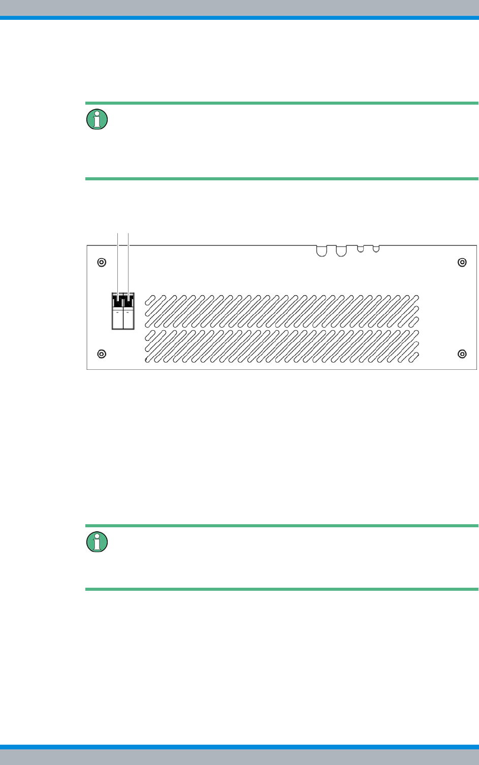
DIB-500 R4.1 Service interruption
Permanent service interruption
164 Installation, Operation and Service Manual 90DIB500R41IM_FCC02 – 99.1
Turn off the power supply
Carry out the following steps:
Voltage supply of the other components
If the DIB-500 R4.1 is operated with VAC voltage supply, the voltage supply unit will still
be live when the on/off switches are switched to off.
1. Switch off the voltage supply by flipping down the On/Off switch; refer to Figure 8.1.
Figure 8.1 On/off switch
➥The hardware components are switched off.
2. Switch off the voltage source at the location. Alternatively you can switch off the
fuse of the sub-distribution.
3. Use a voltmeter to check whether the supply lines from the voltage source at the
location are de-energised.
4. Check whether all LED displays of the hardware components and the SC200 are
inactive.
✓You have turned off the power supply.
Recommissioning
The required recommissioning will be pointed out in the corresponding sections.
8.2 Permanent service interruption
The following chapter describes the procedure for performing a permanent shutdown of
the product properly.
For a permanent service interruption, all physical connections routed to the outside
must be disconnected in addition to the temporary service interruption. This requires
that the operation of the network element has already been interrupted temporarily.
1 2
Installation, Operation and Service Manual 90DIB500R41IM_FCC02 – 99.1 165
DIB-500 R4.1 Service interruption
Permanent service interruption
Table 8.2 provides an overview of the order for disconnecting physical connections from
network elements.
Permanent service interruption
Preparation:
✓The operation of the network element must have been interrupted temporarily, refer
to section 8.1 on page 163.
Carry out the following steps:
➔Remove any physical connections from the network element accordingly Table 8.2.
✓The equipment rack has now been shut down permanently.
Recommissioning
For recommissioning after a permanent shutdown, proceed as described in section 9.2
on page 168.
Table 8.2 Disconnecting physical connections (order)
Order Physical connection
1. Voltage Supply Cable
2. Antenna cable:
|GPS antenna
|TETRA antenna(s)
|External antenna coupling systems
3. Ethernet cable

DIB-500 R4.1 Service interruption
Permanent service interruption
166 Installation, Operation and Service Manual 90DIB500R41IM_FCC02 – 99.1
Installation, Operation and Service Manual 90DIB500R41IM_FCC02 – 99.1 167
DIB-500 R4.1 Recommissioning
Recommissioning after a temporary service interruption
9 Recommissioning
This chapter describes the procedures for putting the product back into operation.
The following recommissioning situations are distinguished:
|Recommissioning after a temporary service interruption
|Recommissioning after a permanent service interruption
9.1 Recommissioning after a temporary service interrup-
tion
To recommission the product, you either have to connect the equipment rack to the volt-
age source or switch it on, depending on the connection variant.
Table 9.1 provides an overview of possible connection types and describes required
procedures for connection to the voltage source.
When switching on the product, all the hardware components will automatically be
started. After about three to five minutes, all hardware components have started up and
are ready for operation.
Proceed as follows to recommission a network element after a temporary service inter-
ruption:
Preparation:
✓The equipment rack must be connected to the grounding system.
✓The voltage source on site must be switched off. This must have been checked
with a voltmeter.
Carry out the following steps:
1. Connect the equipment rack to the voltage source on site depending on the con-
nection variant, refer to Table 9.1 on page 167.
2. Switch the voltage source at the location on again, see section Recommissioning
after a temporary service interruption on page 167.
3. Switch on the product, refer to section Recommissioning after a temporary service
interruption on page 167.
✓You have successfully recommissioned a network element.
Table 9.1 Connection types and procedures for connection with the voltage source
Connector type Procedure
Fixed connection (e.g.
distributor box) Set the corresponding toggle switch on site to the "On" switch set-
ting or energize the fixed connection via a fuse.
Schuko plug Connect the plug to the mains socket.

DIB-500 R4.1 Recommissioning
Recommissioning after a permanent service interruption
168 Installation, Operation and Service Manual 90DIB500R41IM_FCC02 – 99.1
9.2 Recommissioning after a permanent service interrup-
tion
The present section describes the proper procedure for recommissioning after a perma-
nent shutdown of the product. For this purpose, the disconnected physical connections
must be restored.
Proceed as follows to recommission a network element after a permanent shutdown:
Preparation:
✓The equipment rack must be connected to the grounding system.
✓The component rack must be connected to the voltage supply.
✓The voltage supply must be switched off.
Carry out the following steps:
1. Connect the antennas, refer to section 5.15 on page 129.
2. Connect the required cables, refer to section 5.6 on page 107 and section 5.7 on
page 113.
3. Switch on the voltage source, see section 5.14 on page 129.
4. Switch on the DIB-500 R4.1, see section 5.15 on page 129.
✓You have successfully recommissioned a network element.
Installation, Operation and Service Manual 90DIB500R41IM_FCC02 – 99.1 169
DIB-500 R4.1 Maintenance
Maintenance tasks
10 Maintenance
To ensure the proper operation of products, maintenance tasks and periodical visual
inspections are required.
The products have been designed for permanent and unsupervised operation. For this
reason, maintenance need not be performed according to a fixed schedule. Still you
should make checks from time to time. While doing so, you can look out for any dirt in
the vicinity of or inside equipment racks and remove it if required to insure that the air
supply and heat dissipation of the product are not affected.
The topical state of the hardware components can be monitored via a connected net-
work management client (NMC-511 FaultManager). For more information on the
NMC-511 FaultManager, please refer to the product documentation of the NMC-511
FaultManager.
10.1 Maintenance tasks
Contaminations may impair the air supply and heat output and possibly affect the oper-
ation. For this reason, the activities listed below should be performed in the interval
specified.
Early fan replacement
Independent of the ambient conditions at the installation site, the fan may have to be
replaced earlier. For this reason, please comply with the recommended visual inspec-
tions and intervals.
10.2 Periodical visual inspections
The table below lists the recommended tasks for maintaining the products. The visual
inspections should be performed in the intervals specified to be able to respond in due
time, e.g. in the case of changes at the location that may result in improper operation.
We recommend logging the results of the inspection.
Table 10.1 Maintenance work
Task/s Interval/s
Replace the fan after 40,000 operating hours (corresponds to
approx. five years)
Replace the air filter pad Depends on the environmental conditions
DIB-500 R4.1 Maintenance
Periodical visual inspections
170 Installation, Operation and Service Manual 90DIB500R41IM_FCC02 – 99.1
Replacing components
If faults of or damage to components occur, the component affected including the
installed software component(s) may have to be replaced.
Table 10.2 Tasks to be performed during visual inspections and intervals
Task/s Interval/s1)
1) depending on the respective environmental conditions at the site of the product, shorter
intervals may be required
Site inspection based on the document "Site Requirements“, such
as the inspection of the:
|Grounding facility
|Voltage supply connection
|Installation location of the GPS antenna
|Condition and fit of all the supply lines and replacement of
supply lines as required.
|Upon location
changes
|Once every year
Check the condition of the product in respect of:
|Readiness for operation
|Dirt and dust accumulations on and in the equipment rack,
clean if required
|Check the degree of soiling of the contact pins, remove any
dirt if required.
|Proper operation of the fan unit; replace the air filter pad as
required.
Once every year
Perform a function test of the external alarms – if connected Once every year
Checking standby carriers – if available Once every year
Checking external antenna coupling systems Project specific2)
2) The use of external antenna coupling systems is project specific and dependent on the
antenna coupling systems used. The operator alone is responsible for properly che-
cking external antenna coupling systems.

Installation, Operation and Service Manual 90DIB500R41IM_FCC02 – 99.1 171
DIB-500 R4.1 Component replacement
Safety measures and prerequisites
11 Component replacement
This chapter describes the component replacement of hardware components and, if
necessary, the configuration or the software update of installed software components.
The safety measures to be followed and prerequisites for the corresponding tasks are
described in section 11.1 on page 171. The hardware components that can be replaced
are described in section 11.2 on page 172. Tools, aids and materials required for the
replacement are described in section 11.2 on page 172.
The product has been designed for continuous operation. In a few cases, however, it
may be required to replace installed hardware components and/or update software
components installed on the hardware components.
Possible reasons:
|Replacement due to network optimisation
|Replacement due to disruption in operation
11.1 Safety measures and prerequisites
For the component replacement, the following safety measures and prerequisites must
be observed:
|The safety regulations must be considered at all times, see chapter 2 on page 21.
|Observe all other activity-based safety measures and prerequisites in the activity
descriptions in this chapter.
|The front of the equipment cabinet must be accessible (clearance of at least 700
mm, refer to the document "Site Requirements").
|It must be possible to completely open or remove the cabinet door(s) and the top
cover.
|Required tools, aids and materials must be available, see section 11.2 on page 172.
|Note that the component replacement of individual hardware components may
require preparatory and finalising tasks. The are described at the beginning of the
corresponding section.
|Keep all the materials such as fastening screws in a safe place. You will need them
again.
|Cables to be removed must be reconnected correctly when the component is
installed. Mark the cables accordingly to ensure that they are connected properly.
DIB-500 R4.1 Component replacement
Overview of replacement components and tools, aids and materials
172 Installation, Operation and Service Manual 90DIB500R41IM_FCC02 – 99.1
11.2 Overview of replacement components and tools, aids
and materials
Every replacement component can be uniquely identified via a part number. Please
specify the corresponding part number when ordering. In case of questions concerning
replacement components and part numbers, please contact Rohde & Schwarz Profes-
sional Mobile Radio GmbH.
Table 11.1 provides an overview of replacement components whose replacement is
described in this chapter.
11.2.1 Replacing the TIB transceiver module (tools and aids)
Table 11.2 provides an overview of the tools and aids that are required for replacing the
TIB transceiver module.
Table 11.1 Overview of replacement components
Replacement component Replacement is described in Tools, aids and materials
described in
TETRA Indoor Base station transceiver
(TIB) Section 11.3 on page 175 Section 11.2.1 on page 172
Antenna Coupling System (ACS) Section 11.4 on page 179 Section 11.2.2 on page 173
Air filter mat Section 11.5.1 on page 184 Section 11.2.3 on page 173
Fan subrack Section 11.5.2 on page 187
LAN Routing Unit (LRU) Section 11.6 on page 188 Section 11.2.4 on page 173
Top hat rail power supply unit for operating
the LRU Section 11.7 on page 190 Section 11.2.5 on page 173
Voltage supply unit Rectifier module Section 11.8 on page 192 Section 11.2.6 on page 174
Mounting frame
Cavity coupler Section 11.9 on page 218 Section 11.2.7 on page 174
GPS protector (optional) Section 11.10 on page 221 Section 11.2.8 on page 175
Table 11.2 Overview of tools and aids (replacing the TIB)
Work step Tools, aids
Replacing the TIB |Torx screwdriver size TX25
|Flat-bladed screwdriver size 0.6 x 3.5
|Wrench size 8
|Wrench size 19
|Size 8 dynamometric key with a torque of 0.6 Nm
|Size 19 dynamometric key with a torque of 1 Nm
Software update and
configuration of the TIB |according to the configured service computer, refer to the Con-
figuration Manual "Service Computer for ACCESSNET®-T IP"
|Straight through ethernet cable
Installation, Operation and Service Manual 90DIB500R41IM_FCC02 – 99.1 173
DIB-500 R4.1 Component replacement
Overview of replacement components and tools, aids and materials
11.2.2 Replacing the ACS (tools and aids)
Table 11.3 provides an overview of tools and aids that are required for replacing the
ACS.
11.2.3 Replacing components of the fan unit (tools, aids and materials)
Table 11.4 provides an overview of tools, aids and materials that are required for replac-
ing components of the fan unit.
11.2.4 Replacing the LRU (tools and aids)
Table 11.5 provides an overview of tools and aids that are required for replacing the
LRU.
11.2.5 Replacing the top hat rail power supply unit (tools and aids)
Table 11.6 provides an overview of tools and aids that are required for replacing the top
hat rail power supply unit.
Table 11.3 Overview of tools and aids (replacing the ACS)
Work step Tools, aids
Replacing the ACS |Torx screwdriver size TX25
|Flat-bladed screwdriver size 0.6 x 3.5
|Wrench size 8
|Wrench size 19
|Size 8 dynamometric key with a torque of 0.6 Nm
|Size 19 dynamometric key with a torque of 1 Nm
Table 11.4 Overview of tools, aids and materials (replacing components of the fan unit)
Work step Tools, auxiliaries Materials
Replacing the air filter pad --- |new air filter pad
Replacing the fan subrack |Torx screwdriver size TX20 ---
Table 11.5 Overview of tools and aids (replacing the LRU)
Work step Tools, auxiliaries
Removing the top
cover of the equipment
rack
|Phillips head screwdriver size PH2
|Coin to unscrew/tighten the mounting screws of the equipment
rack top cover
Table 11.6 Overview of tools and aids (replacing the top hat rail power supply unit)
Work step Tools, auxiliaries
Removing the top cover of the
equipment rack |Phillips head screwdriver size PH2
|Coin to unscrew/tighten the mounting screws of the
equipment rack top cover
Replacing the top hat rail power
supply unit – optional, only variants
with redundancy package
|Flat-bladed screwdriver size 0.8 x 2.5
|Flat-bladed screwdriver size 0.8 x 4

DIB-500 R4.1 Component replacement
Overview of replacement components and tools, aids and materials
174 Installation, Operation and Service Manual 90DIB500R41IM_FCC02 – 99.1
11.2.6 Replacing components of the mounting frame/the voltage supply
unit (tools, aids and materials)
Table 11.7 provides an overview of tools, aids and materials that are required for replac-
ing components of the mounting frame/the voltage supply unit.
11.2.7 Replacing cavity couplers (tools and aids)
Table 11.8 provides an overview of tools and aids that are required for replacing cavity
couplers.
Table 11.7 Overview of tools, aids and materials (replacing components of the mounting frame/voltage supply unit
Work step Tools, aids Materials
Replacing rectifier
modules – optional |No. 2 Phillips head screwdriver
|Size 2 Torque/Phillips head screw-
driver with a torque of 1.5 Nm
|Material for securing empty rack open-
ings, such as dummy plates
Removing the top
cover of the equipment
rack
|Phillips head screwdriver size PH2
|Coin to unscrew/tighten the mounting
screws of the equipment rack top
cover
---
Removing the top
cover of the equipment
rack
|No. 1 Phillips head screwdriver ---
Replacing the mount-
ing frame |Torx screwdriver size TX25
|Wrench size 10
|No. 1 Phillips head screwdriver
|Wrench size 4
|Combination pliers
|file
|Cable tie
Configuring the SC200
– optional |according to the configured service
computer, refer to the Configuration
Manual "Service Computer for
ACCESSNET®-T IP"
|Straight through ethernet cable or USB
---
Table 11.8 Overview of tools and aids (replacing cavity couplers)
Work step Tools, auxiliaries
Replacing a cavity cou-
pler |Phillips head screwdriver size PH2
|Coin to unscrew/tighten the mounting screws of the equipment
rack top cover
Setting a cavity coupler
to the TX frequency |according to the configured service computer, refer to the Con-
figuration Manual "Service Computer for ACCESSNET®-T IP"
|Straight through ethernet cable
|VSWR measuring instrument, recommended:
– R&S NRT measuring device and the appropriate adapter
– NRT-Z44 measuring head and the appropriate adapter
|RF connecting cable for connection with the VSWR measuring
instrument
|Dummy load (50 Ω)
|Screw driver/spanner for loosening the mounting screw of the
cavity combiner (depending on the variant)
Installation, Operation and Service Manual 90DIB500R41IM_FCC02 – 99.1 175
DIB-500 R4.1 Component replacement
Replacing the TIB
11.2.8 Replacing the GPS protector (tools and aids)
Table 11.9 provides an overview of the tools and aids that are required for replacing the
GPS Protector.
11.3 Replacing the TIB
An equipment rack can hold as many as two TIB transceiver modules with up to two
carriers. If it is required to replace more than one TIB at the same time, we recommend
that you perform all the work steps for removing and installing one TIB before you start
removing and installing another TIB.
The component is mounted on a holding plate and additionally secured to the equip-
ment cabinet with retaining screws. All the cable connections of the component are on
the front. To provide for easy removal/installation, the component features a handle.
The tasks listed in the following table must be performed for the replacement of the TIP
transceiver module.
Table 11.9 Overview of tools and aids (replacing the GPS protector)
Work step Tools, aids
Replacing the GPS
protector |Size 18 dynamometric key with a torque of 100 Ncm
Table 11.10 Overview of the tasks to be performed (Replacing the TIB)
Tasks/work steps Described in
Temporary service interruption Section 8.1 on
page 163
Removing the TIB Section 11.3.1 on
page 177
Installing the TIB Section 11.3.2 on
page 178
Recommissioning after a temporary service interruption Section 9.1 on
page 167
Software update and configuration of the TIB Section 11.3.3 on
page 179
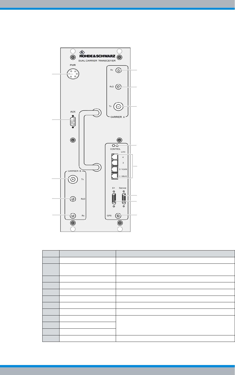
DIB-500 R4.1 Component replacement
Replacing the TIB
176 Installation, Operation and Service Manual 90DIB500R41IM_FCC02 – 99.1
Figure 11.1 shows the front view of the TIB. The following table describes these indica-
tors in detail.
Figure 11.1 TIB (front view)
Table 11.11 Legend: TIB (front view)
No. Name of connection Description
1 PWR 48 VDC voltage supply connection
2 AUX Interface to the antenna connection (Antenna Coupling
System, ACS), including voltage supply
3 Tx (Carrier B) Tx transmitter output carrier B
4 RxD (Carrier B) Rx receiver input carrier B (Diversity)
5 Rx (Carrier B) Rx receiver input carrier B
6 Rx (Carrier A) Rx receiver input carrier A
7 RxD (Carrier A) Rx receiver input carrier A (Diversity)
8 Tx (Carrier A) Tx transmitter output carrier A
9 LAN (4) Ethernet ports, described in Table 3.20 on page 46
10 LAN (3)
11 LAN (1/SBUS)
12 GPS GPS antenna connector
1
2
3
4
5
7
6
8
9/10
12
13
14
11
Installation, Operation and Service Manual 90DIB500R41IM_FCC02 – 99.1 177
DIB-500 R4.1 Component replacement
Replacing the TIB
11.3.1 Removing the TIB
The procedure for removing the TIB is described below.
Proceed as follows to remove the TIB:
Preparation:
✓The preparatory measures must be completed, refer to Table 11.10 on page 175.
✓The tools and aids must be available, refer to section 11.2.1 on page 172.
Carry out the following steps:
Risk of damage
Installed components may be damaged. All the HF connections within the network ele-
ment may only be established/disconnected when the network element is disconnected
from the mains.
➔Ensure that the voltage supply of the component to be replaced is switched off
before you perform any work on the component.
Risk of injury
The equipment rack features sharp edges on the inside. Risk of injury if you do not wear
protective gloves.
➔Always wear protective gloves for the following process steps.
1. Disconnect all the cables connected to the component.
Proceed as follows:
|Remove the power supply cable, see (1) in Figure 11.1 on page 176.
|Remove all Ethernet cables, see (9) to (11) in Figure 11.1 on page 176.
|Remove all cables at the Rx receiver inputs and at the GPS antenna connection
using a wrench size 8, see (4) to (7) and (12) in Figure 11.1 on page 176.
|Remove all cables at the Tx transmitter outputs using a wrench size 19, see (3)
and (8) in Figure 11.1 on page 176.
|Remove the cable at the port for the "AUX" antenna connection using a flathead
screwdriver size 0.6 x 3.5, see (2) in Figure 11.1 on page 176.
2. Loosen the mounting screws of the component on the front of the equipment rack
using a Torx screwdriver size TX25.
DIB-500 R4.1 Component replacement
Replacing the TIB
178 Installation, Operation and Service Manual 90DIB500R41IM_FCC02 – 99.1
Risk of damage
Risk of damage due to high weight (19 kg). The TIB may fall when pushing it in/pulling it
out and damage other components.
➔When pulling the TIB out, additionally support it from below with your other hand.
3. Now cautiously pull the component out along the holder.
✓The removal of the TIB has been completed.
11.3.2 Installing the TIB
The procedure for installing the TIB is described below.
Proceed as follows to install the TIB:
Preparation:
✓The preparatory measures must be completed, refer to Table 11.10 on page 175.
✓The tools and aids must be available, refer to section 11.2.1 on page 172.
✓You need the mounting screws removed with the component.
Carry out the following steps:
Risk of damage
Risk of damage due to high weight (19 kg). The TIB may fall when pushing it in/pulling it
out and damage other components.
➔When pulling the TIB out, additionally support it from below with your other hand.
Risk of injury
The equipment rack features sharp edges on the inside. Risk of injury if you do not wear
protective gloves.
➔Always wear protective gloves for the following process steps.
1. Cautiously slide in the component along the holding plate from the front until the
connecting pins on the rear of the component slide into the openings provided.
2. Retighten the attachment screws of the component on the front of the equipment
cabinet. Use a Torx screwdriver size TX 25 for this purpose.
3. Properly reconnect all the cables to the component.
Installation, Operation and Service Manual 90DIB500R41IM_FCC02 – 99.1 179
DIB-500 R4.1 Component replacement
Replacing the ACS
Proceed as follows:
|Connect the corresponding cable at the port for the "AUX" antenna connection
using a flathead screwdriver size 0.6 x 3.5, see (2) in Figure 11.1 on page 176.
|Connect the corresponding cables at the Tx transmitter outputs with a dynamo-
metric key size 19 using a torque of 1 Nm, see (3) and (8) in Figure 11.1 on
page 176.
|Connect the corresponding cables at the Rx receiver inputs and at the GPS
antenna connection with a dynamometric key size 8 using a torque of 0.6 Nm,
see (4) to (7) in Figure 11.1 on page 176.
|Connect the Ethernet cables at each of the respective intended ports, see (9) to
(11) in Figure 11.1 on page 176.
|Connect the power supply cable, see (1) in Figure 11.1 on page 176.
4. Perform the concluding tasks, refer to Table 11.10 on page 175.
✓You have successfully installed the TIB.
11.3.3 Software update and configuration of the TIB
The software update and the configuration of the TIB are performed through network
management clients via an Ethernet connection to the service computer.
The tasks listed in the following table must be performed for the configuration of the TIB.
11.4 Replacing the ACS
The component is mounted on a holding plate and additionally secured to the equip-
ment cabinet with retaining screws. All the cable connections of the component are on
the front. To provide for easy removal/installation, the component features a handle.
The tasks listed in the following table must be performed to replace the ACS.
Table 11.12 Overview of the tasks to be performed (Software update and configuration of the TIB)
Tasks/work steps Described in
Connecting the service computer to the TIB transceiver module Section 6.1.2.1
on page 133
Deleting the ARP buffer Section 6.1.3 on
page 134
Configuring and generating network configurations via the NMC-515 ConfigurationManager Section 6.1.4 on
page 134
Creating the download repository Section 6.1.5 on
page 135
Adapting IP addresses (with more than one transceiver module) Section 6.1.6 on
page 135
Performing an initial download via NMC-522 DownloadManager Section 6.1.7 on
page 142
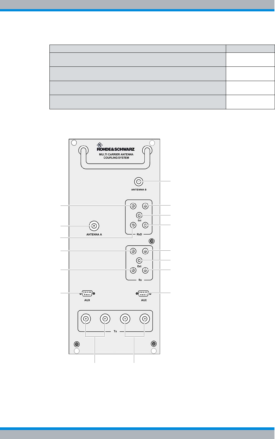
DIB-500 R4.1 Component replacement
Replacing the ACS
180 Installation, Operation and Service Manual 90DIB500R41IM_FCC02 – 99.1
Figure 11.2 shows the front view of the ACS. The following table describes the compo-
nents in greater detail.
Figure 11.2 ACS (front view)
Table 11.13 Overview of the tasks to be performed (Replacing the ACS)
Tasks/work steps Described in
Temporary service interruption Section 8.1 on
page 163
Removing the ACS Section 11.4.1 on
page 181
Installing the ACS Section 11.4.2 on
page 183
Recommissioning after a temporary service interruption Section 9.1 on
page 167
9
6
8
14
11
16
2
15
10
134
5
1
3
7
12
Installation, Operation and Service Manual 90DIB500R41IM_FCC02 – 99.1 181
DIB-500 R4.1 Component replacement
Replacing the ACS
11.4.1 Removing the ACS
The procedure for removing the ACS is described below.
Proceed as follows to remove the ACS:
Preparation:
✓The preparatory measures must be completed, refer to Table 11.10 on page 175.
✓The tools and aids must be available, refer to section 11.2.2 on page 173.
Carry out the following steps:
Risk of injury
The equipment rack features sharp edges on the inside. Risk of injury if you do not wear
protective gloves.
➔Always wear protective gloves for the following process steps.
1. Disconnect all the cables connected to the component.
Table 11.14 Legend: ACS (front view)
No. Supply Description
1 RxD (TIB A1) Antenna B Rx output carrier TIB A1 (only in the case of
diversity)
2 Antenna A Antenna A Tx/Rx antenna connection
3 RxD (TIB A2) Antenna B Rx output carrier TIB A2 (only in the case of
diversity)
4 Rx (TIB A1) Antenna A Rx output carrier TIB A1
5 Rx (TIB A2) Antenna A Rx output carrier TIB A2
6 AUX (TIB A) Interface to the TIB A transceiver module (including voltage
supply)
7 Tx (TIB A1/2)Antenna A1) Tx inputs carrier TIB A1/2
1) depending on the ACS variant
8 Tx (TIB B1/2)Antenna A1) Tx inputs carrier TIB B1/2
9 Antenna B Antenna B (Tx)/Rx antenna connection
10 RxD (TIB B1) Antenna B Rx output carrier TIB B1 (only in the case of
diversity)
11 RxD Ext Interface (input) for connecting the reception paths of
another ACS for diversity reception (with > 4 carriers)
12 RxD (TIB B2) Antenna B Rx output carrier TIB B2 (only in the case of
diversity)
13 Rx (TIB B1) Antenna A Rx output carrier TIB B1
14 Rx Ext Antenna A interface (output) for connecting another ACS
(with >4 carriers)
15 Rx (TIB B2) Antenna A Rx output carrier TIB B2
16 AUX (TIB B) Interface to the TIB B transceiver module (including voltage
supply)
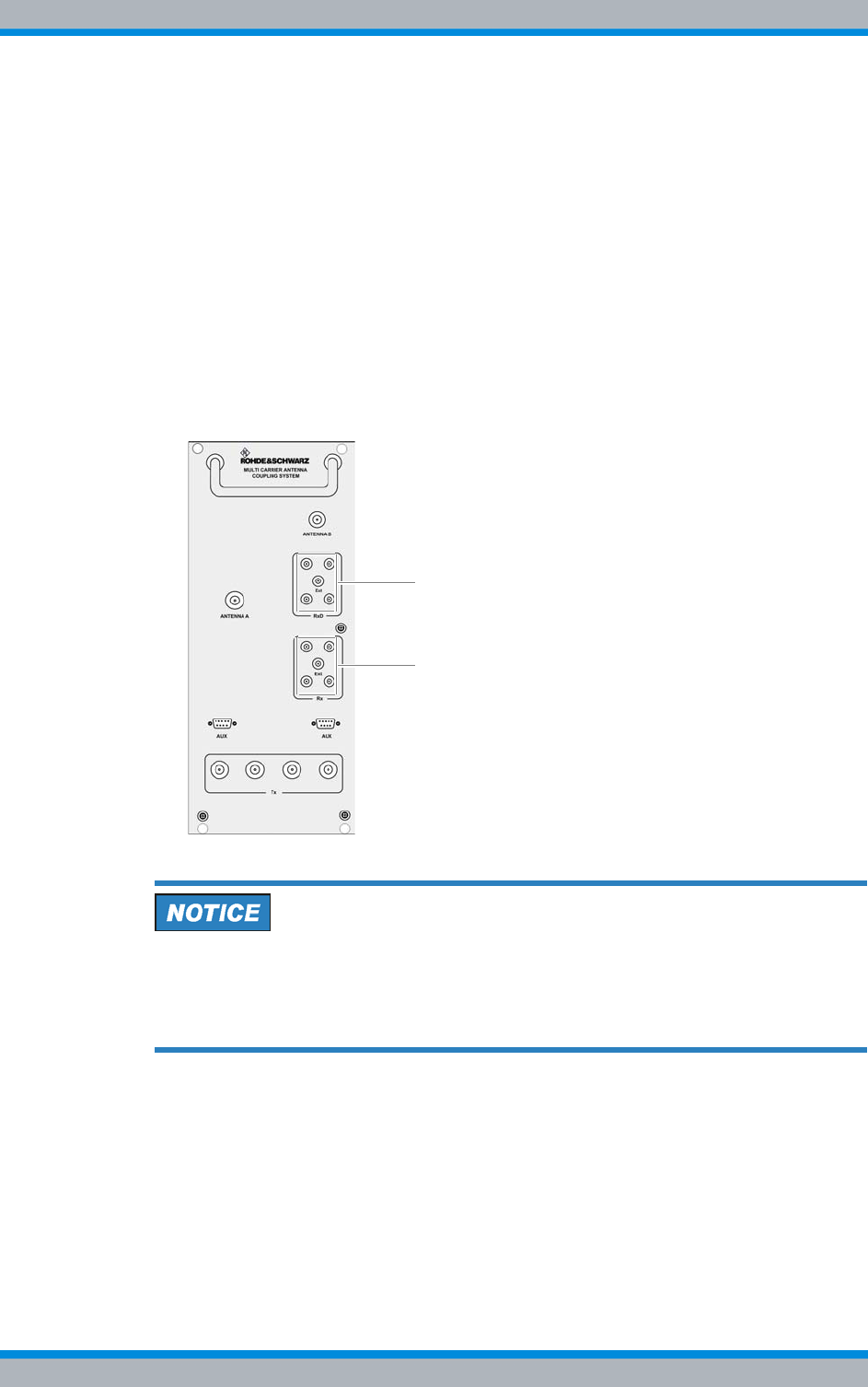
DIB-500 R4.1 Component replacement
Replacing the ACS
182 Installation, Operation and Service Manual 90DIB500R41IM_FCC02 – 99.1
Proceed as follows:
|Remove the cable at the "AUX" port using a flathead screwdriver size 0.6 x 3.5,
see (6) in Figure 11.2 on page 180.
|Remove the cables at ports "Antenna A" and "Antenna B" as well as at the
antenna inputs "Tx" using a wrench size 19, see (2), (7) and (8) in Figure 11.2 on
page 180.
|Remove the cables at the antenna outputs "Rx" and "RxD" using a wrench size 8,
see (1) and (3) to (5) in Figure 11.2 on page 180.
2. Loosen the mounting screws of the component on the front of the equipment rack
using a Torx screwdriver size TX25.
3. Remove the terminating resistors (if available, variant-dependent) from the Rx mul-
ticouplers on the front cover of the ACS by screwing them off using the size 8
wrench, refer to Figure 11.3.
Figure 11.3 ACS front view - terminating resistors (variant-dependent)
Risk of damage
Risk of damage due to high weight (16 kg). The ACS may fall when pushing it in/pulling
it out and damage other components.
➔When pulling the ACS out, additionally support it from below with your other hand.
4. Now cautiously pull the component out along the holder.
✓You have successfully removed the ACS.
Installation, Operation and Service Manual 90DIB500R41IM_FCC02 – 99.1 183
DIB-500 R4.1 Component replacement
Replacing the ACS
11.4.2 Installing the ACS
The procedure for installing the ACS is described below.
Proceed as follows to install the ACS:
Preparation:
✓The preparatory measures must be completed, refer to Table 11.10 on page 175.
✓The tools and aids must be available, refer to section 11.2.2 on page 173.
✓You need the terminating resistors and fastening screws removed with the compo-
nent.
Carry out the following steps:
Risk of damage
Risk of damage due to high weight (16 kg). The ACS may fall when pushing it in/pulling
it out and damage other components.
➔When pulling the ACS out, additionally support it from below with your other hand.
Risk of injury
The equipment rack features sharp edges on the inside. Risk of injury if you do not wear
protective gloves.
➔Always wear protective gloves for the following process steps.
1. Cautiously slide in the component along the slide rail holder from the front until the
connecting pins on the rear of the component slide into the openings provided.
2. If available, mount the terminating resistors (variant-dependent) properly on the
front cover of the ACS again applying a tightening torque of 0.6 Nm with a size 8
dynamometric key, refer to Figure 11.2 on page 180 and Figure 11.3 on page 182.
3. Retighten the attachment screws of the component on the front of the equipment
cabinet. Use a Torx screwdriver size TX 25 for this purpose.
4. Properly reconnect all the cables to the component.
Proceed as follows:
|Connect the corresponding cables at the antenna outputs "Rx" and "RxD" with a
dynamometric key size 8 using a torque of 0.6 Nm, see (1) and (3) to (5) in Figure
11.3 on page 182.
|Connect the corresponding cables at the ports "Antenna A" and "Antenna B" as
well as at the antenna inputs "Tx" with a dynamometric key size 19 using a torque
of 1 Nm, see (2), (7) and (8) in Figure 11.3 on page 182.
|Connect the corresponding cables at the "AUX" port using a flathead screwdriver
size 0.6 x 3.5, see (6) in Figure 11.3 on page 182.
5. Verify that all the connections made are properly connected.
6. Perform the concluding tasks, refer to Table 11.10 on page 175.
✓The installation of the ACS has been completed.
DIB-500 R4.1 Component replacement
Replacing fan unit constituents
184 Installation, Operation and Service Manual 90DIB500R41IM_FCC02 – 99.1
11.5 Replacing fan unit constituents
You can replace the air filter pad or the entire fan unit of the DIB-500 R4.1. The proce-
dures for this are described in the following sections.
|Replacing the air filter pad
|Replacing the fan subrack
11.5.1 Replacing the air filter pad
The fan insert is equipped with an air filter pad that removes dirt and dust particles from
the supply air. The air filter pad is accessible via the front side of the equipment rack.
The air filter pad can be hot-swapped. The fan subrack need not be removed for replac-
ing the air filter pad. The air filter pad holder is made up of a plate and a fastener,
between which the air filter pad is fixed.
The tasks listed in the following table must be performed for the replacement of the air
filter pad.
11.5.1.1 Removing the air filter pad
The air filter pad is fastened in an air filter pad holder that is secured to the fan insert
with two mounting screws.
Table 11.16 describes the positions of the air filter pad holder mounting screws and their
significance.
Table 11.15 Overview of the tasks to be performed (Replacing the air filter pad)
Tasks/work steps Described in
Removing the air filter pad Section 11.5.1.1 on page 184
Installing the air filter pad Section 11.5.1.2 on page 185
Table 11.16 Positions of the air filter pad holder mounting screws
Position Description
Locked
Unlocked
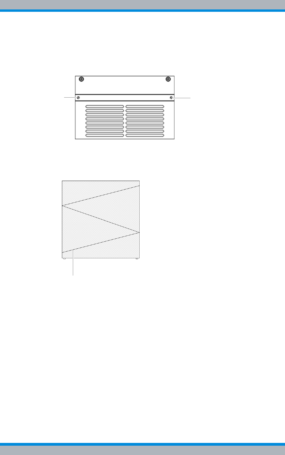
Installation, Operation and Service Manual 90DIB500R41IM_FCC02 – 99.1 185
DIB-500 R4.1 Component replacement
Replacing fan unit constituents
Proceed as follows to remove the air filter pad:
Carry out the following steps:
1. Turn the air filter pad holder mounting screws by 90° to loosen them, refer to Figure
11.4.
Figure 11.4 Air filter pad holder mounting screws
2. Pull the air filter pad holder out to the front.
3. Remove the fastener of the air filter pad holder by pressing the fastener together
and taking it out of the holder.
Figure 11.5 Air filter pad fastener (top view)
4. Remove the air filter pad.
✓You have successfully removed the air filter pad.
11.5.1.2 Installing the air filter pad
To install the air filter pad, the air filter pad holder must be slid back into the fan insert
and fastened.
Proceed as follows to install the air filter pad:
Preparation:
✓You need the air filter pad and the fastener loosened during the removal.
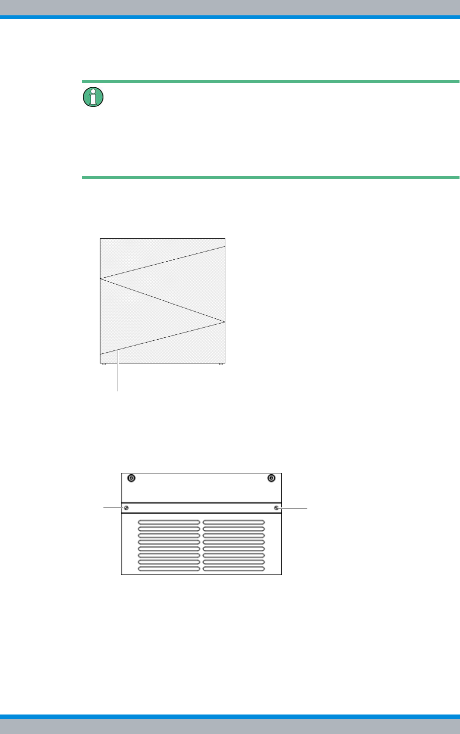
DIB-500 R4.1 Component replacement
Replacing fan unit constituents
186 Installation, Operation and Service Manual 90DIB500R41IM_FCC02 – 99.1
Carry out the following steps:
Positioning the air filter pad
When positioning the air filter pad in the air filter pad holder, ensure that all the edges of
the air filter pad are aligned and make firm contact so that supply air cannot flow past
the air filter pad. Otherwise dirt and dust particles will not be filtered from the supply air
reliably.
1. Position the air filter pad in the air filter pad holder.
2. Press the fastener of the air filter pad holder together to fasten it in the holder
again, refer to Figure 11.6.
Figure 11.6 Fastener of air filter pad holder (top view)
3. Position the air filter pad holder between the two hold points on the sides of the fan
insert.
4. Cautiously slide the air filter pad holder in to the rear.
5. Fit and tighten the air filter pad holder, refer to Figure 11.7.
Figure 11.7 Air filter pad holder mounting screws
✓You have successfully installed the air filter pad.
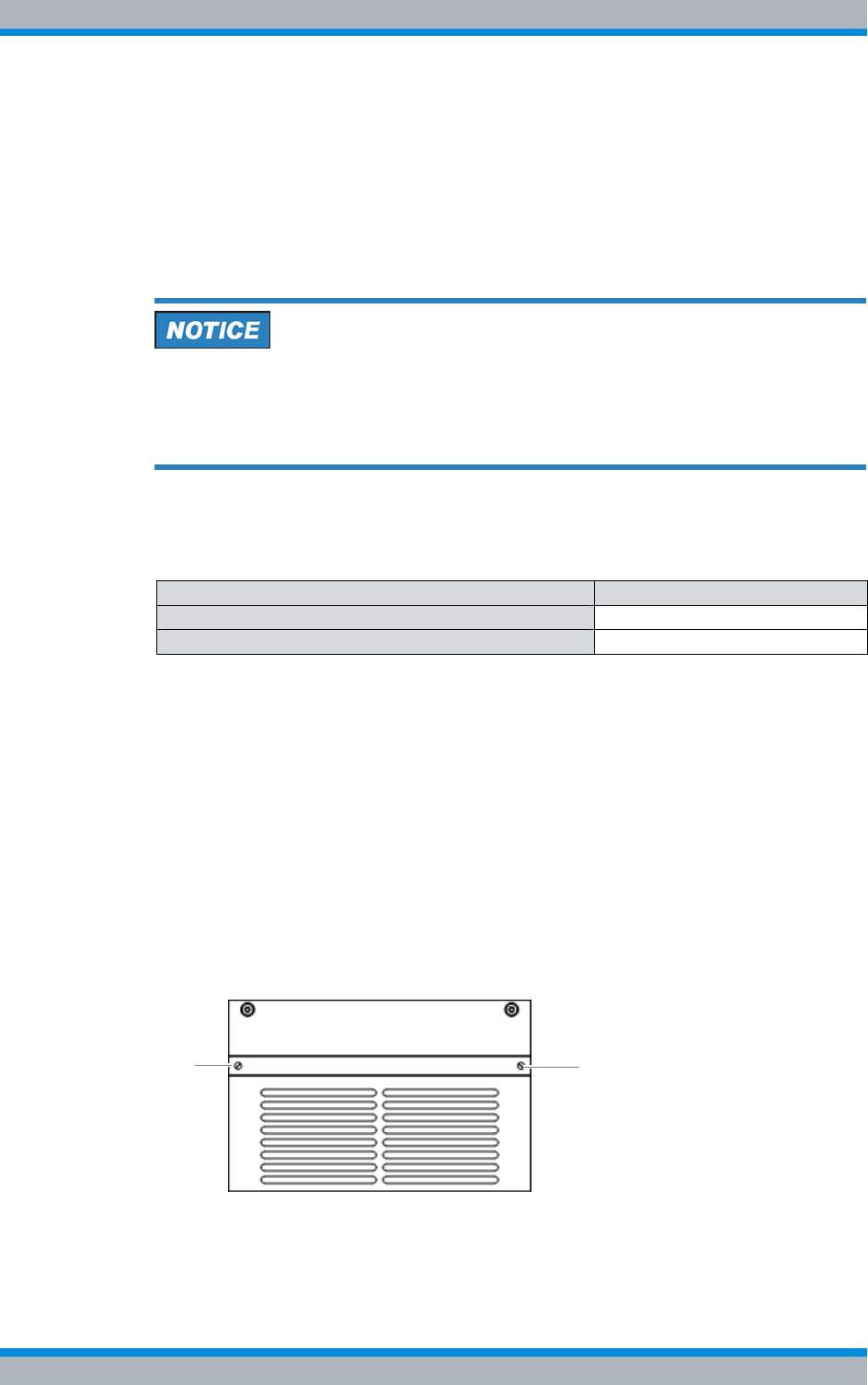
Installation, Operation and Service Manual 90DIB500R41IM_FCC02 – 99.1 187
DIB-500 R4.1 Component replacement
Replacing fan unit constituents
11.5.2 Replacing the fan subrack
The fan insert is suspended on a mounting rail in the equipment rack and secured to the
front of the equipment rack with two mounting screws.
The fan insert can be replaced during operation. In this case, the replacement should
be performed fast. Otherwise the TIB transceiver modules may switch off automatically
as a factor of the ambient conditions.
Risk of overheating
During the operation without fan subrack, it is possible that the corresponding TIB trans-
ceiver module will overheat and be damaged.
➔Ensure that you install the new fan subrack immediately following the removal.
The tasks listed in the following table must be performed for the replacement of the air
filter pad.
11.5.2.1 Removing the fan subrack
The fan insert is equipped with a voltage supply unit. The voltage supply connector (D-
Sub) is on the rear of the fan insert.
Proceed as follows to remove the fan insert:
Preparation:
✓Ensure that the replacement component is available in its area of use.
✓The tools and aids must be available, refer to section 11.2.3 on page 173.
Carry out the following steps:
1. Loosen the mounting screws of the fan insert using a Torx screwdriver size TX20 x
80, refer to Figure 11.8.
Figure 11.8 Fan insert mounting screws
Table 11.17 Overview of the tasks to be performed (Replacing the air filter pad)
Tasks/work steps Described in
Removing the fan subrack Section 11.5.2.1 on page 184
Installing the fan subrack Section 11.5.2.2 on page 188
DIB-500 R4.1 Component replacement
Replacing the LRU – optional (redundancy package)
188 Installation, Operation and Service Manual 90DIB500R41IM_FCC02 – 99.1
Resistance when pulling out the fan insert
Slight resistance will be noticed when pulling out the fan insert. Pull the fan insert out
further to disconnect the voltage supply connector.
2. Cautiously pull out the fan insert to the front along the holder.
✓You have successfully removed the fan insert.
11.5.2.2 Installing the fan subrack
The voltage supply connector will be reconnected when the fan insert is installed. Sub-
sequently, the fan will start automatically.
Proceed as follows to install the fan insert:
Preparation:
✓The tools and aids must be available, refer to section 11.2.3 on page 173.
✓You need the mounting screws removed with the component.
Carry out the following steps:
1. Slide the fan insert in from the front along the holder.
➥The fan will start automatically.
2. Reattach the fan insert to the front of the equipment rack. Use a Torx screwdriver
size TX20 for this purpose.
✓You have successfully installed the fan insert.
11.6 Replacing the LRU – optional (redundancy package)
For variants with redundancy package (hybrid and cavity) a LAN switch (LAN routing
unit, LRU) is additionally used optionally to connect the two equipment racks, i.e. the
TIB transceiver modules installed in the racks.
The tasks listed in the following table must be performed for the replacement of the
LRU.
The LRU and the top hat rail power supply unit are installed on a top hat rail and each
fastened by a lock.
Table 11.18 Overview of tasks to be performed (replacing the LRU)
Tasks/work steps Described in
Preparatory measures Temporary service interruption Section 8.1 on page 163
Removing the top cover of the mounting frame Section 5.4 on page 94
Removing the LRU Section 11.6.1 on page 189
Inserting the LRU Section 11.6.2 on page 190
Concluding tasks Mounting the top cover of the equipment rack Section 5.13 on page 129
Recommissioning after a temporary service inter-
ruption Section 9.1 on page 167
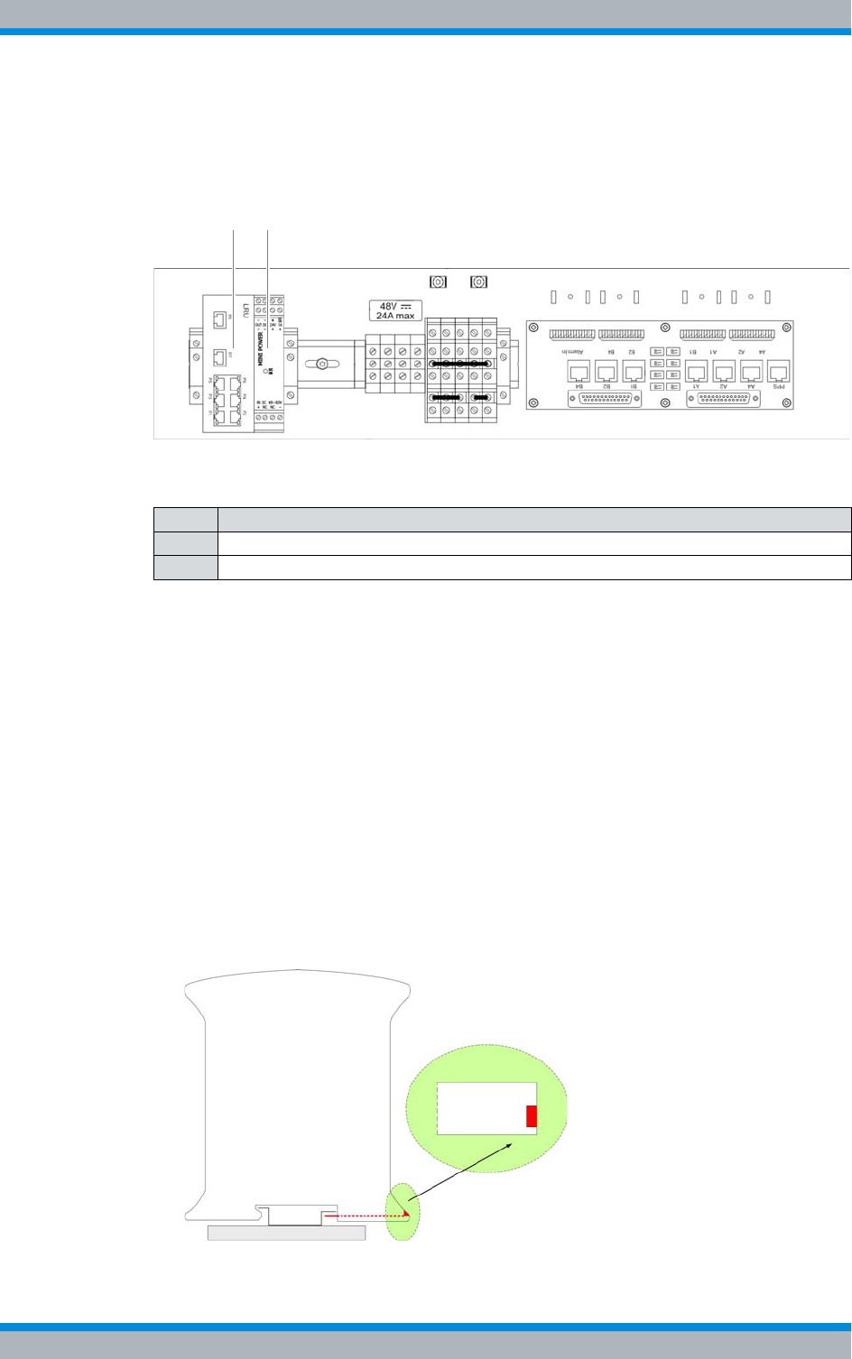
Installation, Operation and Service Manual 90DIB500R41IM_FCC02 – 99.1 189
DIB-500 R4.1 Component replacement
Replacing the LRU – optional (redundancy package)
The LRU is supplied with voltage via a separate top hat rail power supply unit.
Figure 11.9 shows the top view of the installed redundancy package. The following table
describes the additional components in detail.
Figure 11.9 Redundancy package (top view)
11.6.1 Removing the LRU
The LRU is fastened onto the top hat rail with a locking device, see Figure 11.9 on
page 189.
Removing the LRU
Preparation:
✓The network element must have been put out of operation temporarily, refer to sec-
tion 8.1 on page 163.
✓The preparatory measures must be completed, refer to Table 11.10 on page 175.
✓The tools and aids must be available, refer to section 11.2.4 on page 173.
Carry out the following steps:
1. Secure the LRU with your one hand and pull the red locking device away from the
component, refer to Figure 11.10.
Figure 11.10 Locking device of the LRU (section)
Table 11.19 Legend: Redundancy package (top view)
No. Component
1LRU
2 Top hat rail power supply unit of the LRU
1 2
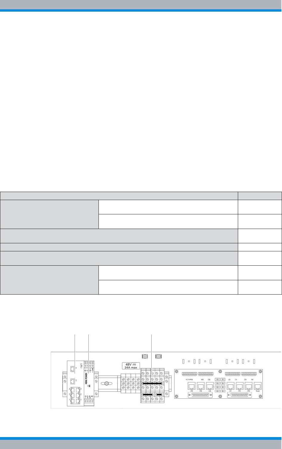
DIB-500 R4.1 Component replacement
Replacing the top hat rail – optional (redundancy package)
190 Installation, Operation and Service Manual 90DIB500R41IM_FCC02 – 99.1
2. Pull the component slightly forward and then upwards off the top hat rail.
3. Remove all the connected cables.
✓The removal of the LRU has thus been completed.
11.6.2 Inserting the LRU
The procedure corresponds to the description in section 5.5.1.3 on page 102.
11.7 Replacing the top hat rail – optional (redundancy
package)
The top hat rail power supply unit is used for the voltage supply of the LRU. For this pur-
pose, the top hat rail power supply unit is connected with the LRU and the terminal
block using two power supply cables.
The tasks listed in the following table must be performed to replace the top hat rail
power supply unit.
Figure 11.11 shows the top hat rail power supply unit on the top hat rail and additional
components. The following table describes these indicators in detail.
Figure 11.11 Top hat rail power supply unit on the top hat rail
Table 11.20 Overview of the tasks to be performed (Replacing the top hat rail – optional (redundancy package))
Tasks/work steps Described in
Preparatory measures Temporary service interruption Section 8.1 on
page 163
Removing the top cover of the mounting frame Section 5.4 on
page 94
Removing the top hat rail power supply unit Section 11.7.1
on page 191
Connecting voltage supply cables to the top hat rail power supply unit on page 100
Installing the top hat rail power supply unit Section 11.7.2
on page 192
Concluding tasks Mounting the top cover of the equipment rack Section 5.13
on page 129
Recommissioning after a temporary service interruption Section 9.1 on
page 167
1 2 3
Installation, Operation and Service Manual 90DIB500R41IM_FCC02 – 99.1 191
DIB-500 R4.1 Component replacement
Replacing the top hat rail – optional (redundancy package)
11.7.1 Removing the top hat rail power supply unit
The top hat rail power supply unit is clamped on with a locking device, refer to Figure
11.11 on page 190.
Proceed as follows to remove the top hat rail power supply unit:
Preparation:
✓The network element must have been put out of operation temporarily, refer to sec-
tion 8.1 on page 163.
✓The upper cover of the equipment rack must have been removed, refer to section
5.4 on page 94.
✓The tools and aids must be available, refer to section 11.2.5 on page 173.
Carry out the following steps:
Risk of injury
The equipment rack features sharp edges on the inside. Risk of injury if you do not wear
protective gloves.
➔Always wear protective gloves for the following process steps.
Risk of electric shock
Electric shock when touching live parts. Hardware components in the equipment cabi-
net are live.
➔When performing work in the equipment cabinet, ensure that the voltage source on
site is switched off. This must have been checked with a voltmeter.
1. Disconnect the voltage supply cables from the top hat rail power supply unit. Us a
size 0.8 x 2.5 flat-bladed screwdriver for this purpose.
Table 11.21 Legend: Top hat rail power supply unit on the top hat rail
No. Designation
1LRU
2 Top hat rail power supply unit of the LRU
3 Terminal block
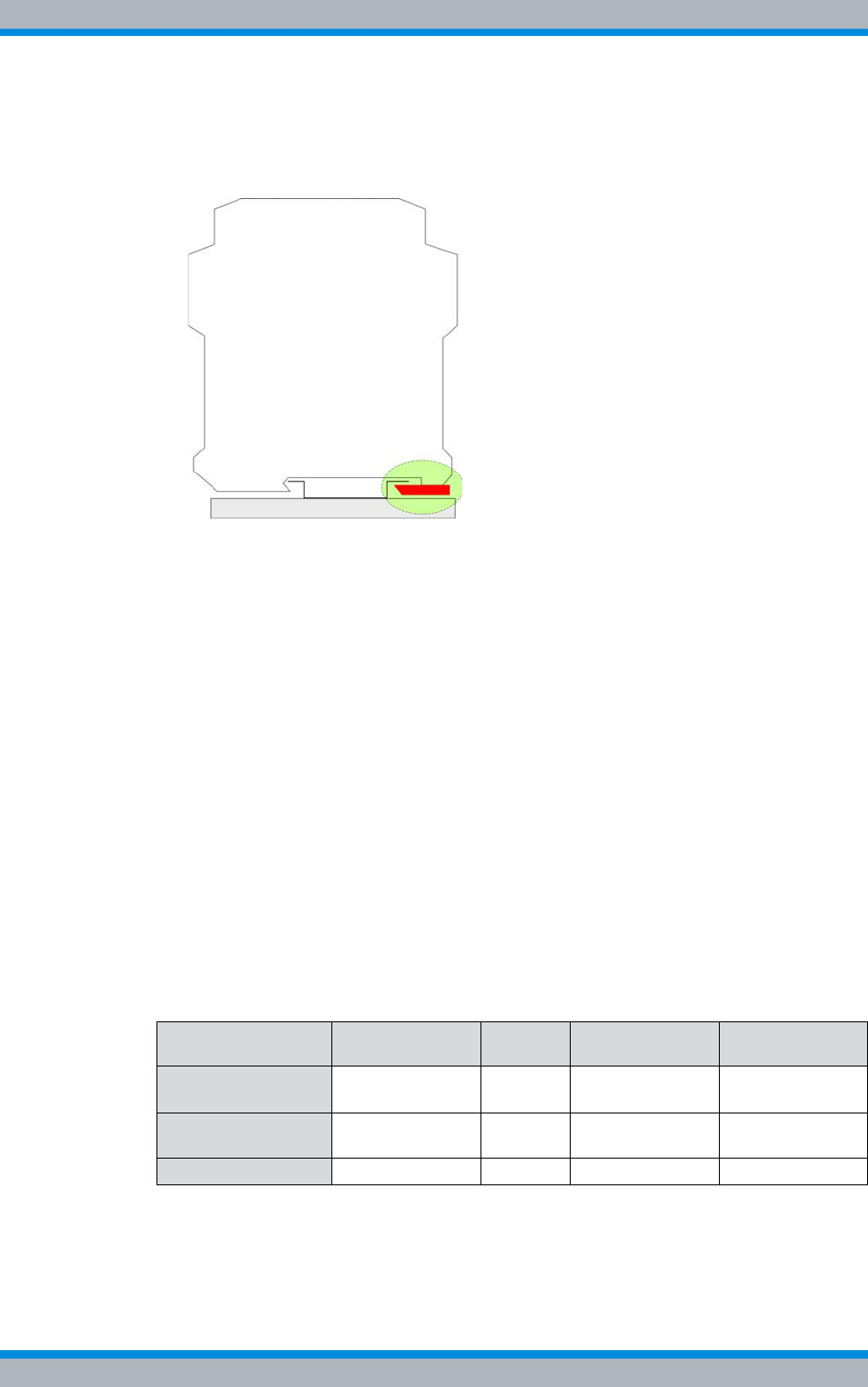
DIB-500 R4.1 Component replacement
Replacing components of the VAC and alarm system expansion – optional
192 Installation, Operation and Service Manual 90DIB500R41IM_FCC02 – 99.1
2. Secure the top hat rail power supply unit with one hand and pull the locking device
away from the component using a size 0.8 x 4 flat-bladed screwdriver, refer to Fig-
ure 11.12.
Figure 11.12 Locking device of top hat rail power supply unit
3. Pull the component slightly forward and then upwards off the top hat rail.
✓You have successfully removed the top hat rail power supply unit.
11.7.2 Installing the top hat rail power supply unit
The procedure corresponds to the description in section 5.5.1.4 on page 103.
11.8 Replacing components of the VAC and alarm system
expansion – optional
The standard design of the DIB-500 R4.1 with VDC voltage supply can be expanded by
a VAC voltage supply unit or by an alarm system expansion. Depending on the design,
additional hardware components are available that can also be replaced.
Table 11.22 provides an overview of the components for the voltage supply and alarm
system of the individual versions of the DIB-500 R4.1.
Table 11.22 Components for voltage supply and alarm system
Version Terminal block SC200 Alarm input/
output module Rectifier mod-
ule
VDC voltage supply
(standard)
x --- --- ---
Alarm system
expansion x x x ---
VAC expansion x x x x
Installation, Operation and Service Manual 90DIB500R41IM_FCC02 – 99.1 193
DIB-500 R4.1 Component replacement
Replacing components of the VAC and alarm system expansion – optional
Table 11.23 provides an overview of replacement components of the VAC and the alarm
system expansion.
11.8.1 Replacing rectifier modules
The rectifier module is a hardware subcomponent of the power supply unit and used for
converting alternating-current voltage (VAC) into direct-current voltage (VDC).
The tasks listed in the following table must be performed to replace the rectifier mod-
ules.
11.8.1.1 Uninstalling rectifier modules
The rectifier module is secured to the mounting frame with a fastening screw.
Remove the rectifier module as follows:
Preparation:
✓The preparatory measures must be completed, refer to Table 11.24 on page 193.
✓The tools and aids must be available, refer to section 11.2.6 on page 174.
Table 11.23 Overview of replacement components (VAC and alarm system expansion)
Replacement component Replacement is described
in
Rectifier module Section 11.8.1 on page 193
SC200 (the SC200 must always be replaced together with the
mounting frame) Section 11.8.2 on page 196
Table 11.24 Overview of the tasks to be performed (Replacing rectifier modules)
Tasks/work steps Described in
Preparatory measures Temporary service interruption Section 8.1 on
page 163
Uninstalling rectifier modules Section 11.8.1.1 on
page 193
Installing rectifier modules Section 11.8.1.2 on
page 195
Concluding tasks Recommissioning after a temporary service
interruption Section 9.1 on
page 167
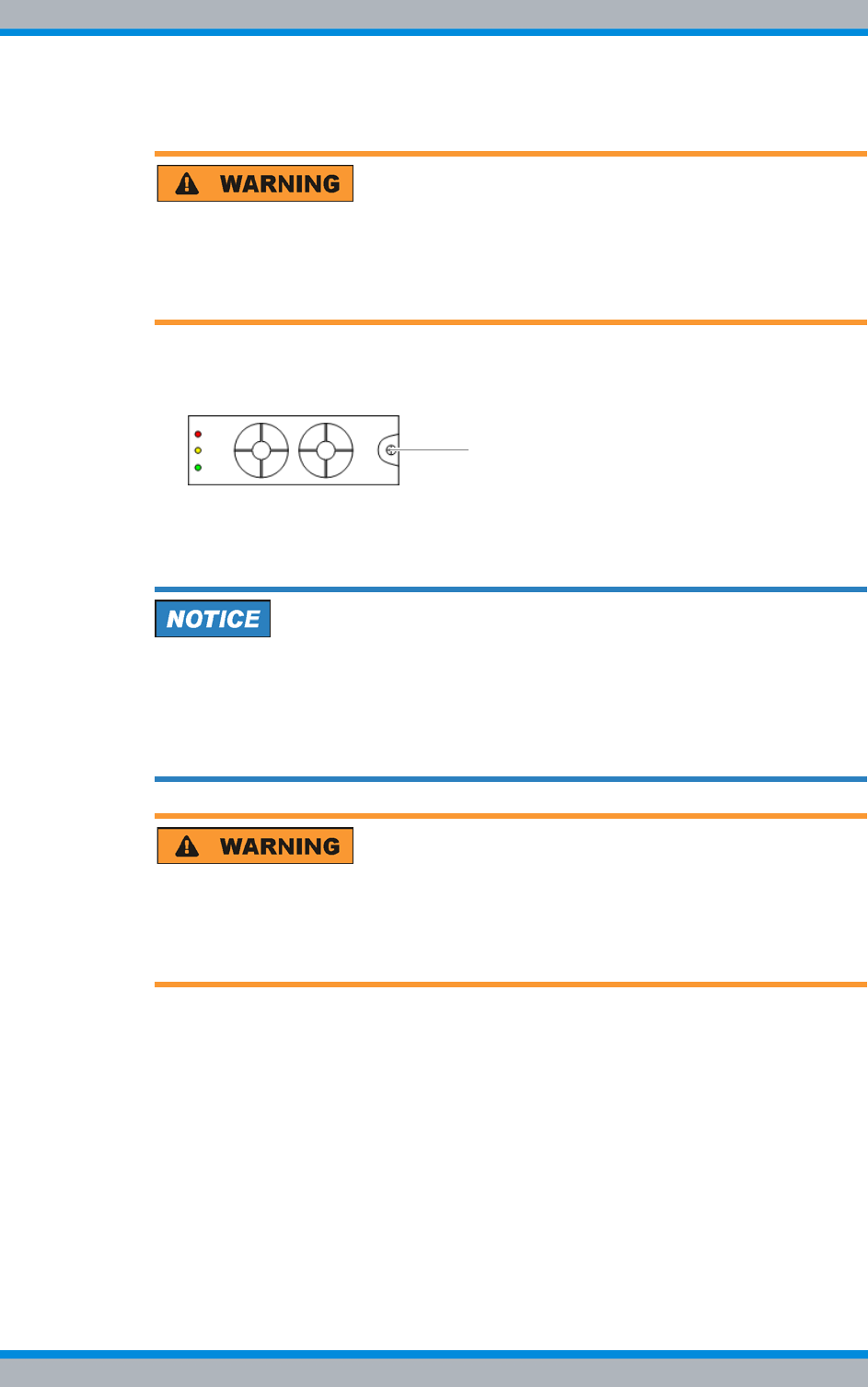
DIB-500 R4.1 Component replacement
Replacing components of the VAC and alarm system expansion – optional
194 Installation, Operation and Service Manual 90DIB500R41IM_FCC02 – 99.1
Carry out the following steps:
Risk of injury
The equipment rack features sharp edges on the inside. Risk of injury if you do not wear
protective gloves.
➔Always wear protective gloves for the following process steps.
1. Loosen the fastening screw of the rectifier module using a size 2 cross-head
screwdriver, refer to Figure 11.13.
Figure 11.13 Rectifier module fastening screw
➥When loosening the fastening screw, the rectifier module is slightly pushed out
of the mounting frame.
Risk of damage
Damage of the component. The connector of the component is on the rear and may be
damaged when stored improperly.
➔Do not place the component on its rear side. Otherwise the connector may be dam-
aged.
Risk of burns
Risk of burns when touching the component. The component may become hot during
operation.
➔Always wear protective gloves when handling the component.
2. Pull the component out of the subrack cautiously.
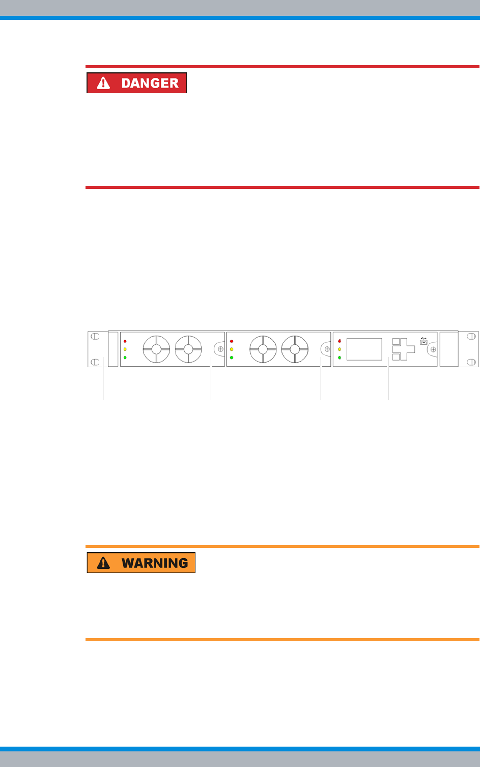
Installation, Operation and Service Manual 90DIB500R41IM_FCC02 – 99.1 195
DIB-500 R4.1 Component replacement
Replacing components of the VAC and alarm system expansion – optional
Risk of electric shock
Electric shock when touching live parts. Hardware components in the equipment cabi-
net are live.
➔When performing work in the equipment cabinet, ensure that the voltage source on
site is switched off.
➔Do not reach into the empty subrack with your hand.
3. Take appropriate measures to safeguard the empty subrack, e.g. through dummy
panels.
✓You have successfully removed the rectifier module.
11.8.1.2 Installing rectifier modules
You have to install the rectifier module in the subrack provided for this purpose, refer to
Figure 11.14.
Figure 11.14 Rectifier mounting frame
Proceed as follows to install a rectifier module:
Preparation:
✓The preparatory measures must be completed, refer to section 11.8 on page 192.
✓The tools and aids must be available, refer to section 11.2.6 on page 174.
✓You need the mounting screw removed with the component.
Carry out the following steps:
1. Remove the subrack safeguard such as dummy panels if installed.
Risk of injury
The equipment rack features sharp edges on the inside. Risk of injury if you do not wear
protective gloves.
➔Always wear protective gloves for the following process steps.
2. Position the rectifier module.
3. Cautiously slide the component into the subrack from the front until the mounting
screw touches the mounting frame.
PSU1 PSU2
2 2 31
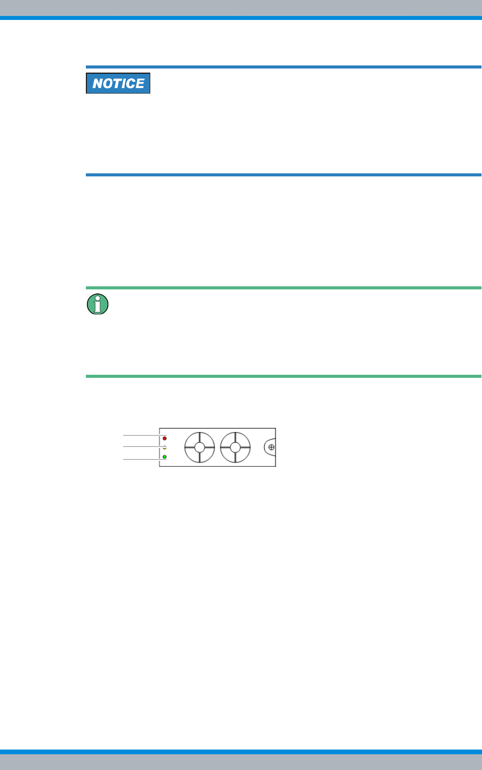
DIB-500 R4.1 Component replacement
Replacing components of the VAC and alarm system expansion – optional
196 Installation, Operation and Service Manual 90DIB500R41IM_FCC02 – 99.1
Risk of damage
Damage of installed components. If you apply excessive force when tightening the
mounting screw, installed components of the equipment rack may be damaged.
➔Use a size 2 torque cross-head screwdriver for tightening the fastening screw.
➔Ensure that the maximum torque does not exceed the following value: 1.5 Nm.
4. Tighten the mounting screw on the mounting frame.
➥The connector of the rectifier module is connected to the mounting frame.
5. Take the network element back to operation to test the function of the rectifier mod-
ule, refer to section 9.1 on page 167.
➥The rectifier module starts automatically.
➥The SC200 detects the rectifier module and loads the required configuration
parameters.
LED Indicator of the rectifier module
The status of the rectifier module is indicated via the LEDs on the front after the initiali-
sation of the SC200. During the initialisation (approx. 90 seconds) the "Power" LED will
light up and the "Minor" LED will flash.
6. Ensure that the "Power" LED (3) is lit and the "Major Alarm" (1) and "Minor Alarm"
(2) LEDs are off, refer to Figure 11.15.
Figure 11.15 Front view of the rectifier module – indicators (LEDs)
7. Perform the concluding tasks, refer to Table 11.24 on page 193.
✓You have successfully installed the rectifier module.
11.8.2 Replacing the mounting frame and the SC200
Depending on the voltage supply and the optional components, the mounting frame
may have different constituents, refer to Table 3.7 on page 37.
The mounting frame is fastened with two retaining brackets that are secured to the
equipment rack on the front with four mounting screws.
3
1
2

Installation, Operation and Service Manual 90DIB500R41IM_FCC02 – 99.1 197
DIB-500 R4.1 Component replacement
Replacing components of the VAC and alarm system expansion – optional
The tasks listed in the following table must be performed to replace the mounting frame.
11.8.2.1 Preparatory measures
Before you can start with the replacement of the mounting frame, the preparatory tasks
listed in the following table must be performed.
Table 11.25 Overview of the tasks to be performed (Replacing the mounting frame and the SC200)
Tasks/work steps Described in
Preparatory measures Temporary service interruption Section 8.1 on
page 163
Removing the top cover of the mounting frame Section 5.4 on
page 94
Removing the top cover of the equipment rack Section 5.12.1 on
page 124
Disconnecting external alarms (via alarm input/output
module) on page 198
Removing connections of the SC200 on page 199
Removing Plugs with Earthing Contact – optional (only
for VAC expansion) on page 200
Uninstalling rectifier modules Section 11.8.1.1 on
page 193
Replacing the mounting frame
and the SC200 Removing the mounting frame on page 201
Preparing the mounting frame on page 203
Installing the mounting frame on page 204
Attaching connectors of the SC200 on page 206
Connecting external alarms Section 5.12.2 on
page 126
Concluding tasks Installing Plugs with Earthing Contact – optional (only for
VAC expansion) on page 207
Mounting the top cover of the mounting frame Section 5.12.3 on
page 128
Mounting the top cover of the equipment rack Section 5.13 on
page 129
Recommissioning after a temporary service interruption Section 9.1 on
page 167
Configuring the SC200 Section 11.8.2.4 on
page 208
Table 11.26 Overview of preparatory measures (Replacing the mounting frame and the SC200)
Tasks/work steps Described in
Temporary service interruption Section 8.1 on
page 163
Removing the top cover of the mounting frame Section 5.4 on
page 94
Removing the top cover of the equipment rack Section 5.12.1 on
page 124
Disconnecting external alarms (via alarm input/output module) on page 198
Removing connections of the SC200 on page 199
Removing Plugs with Earthing Contact – optional (only for VAC expan-
sion) on page 200
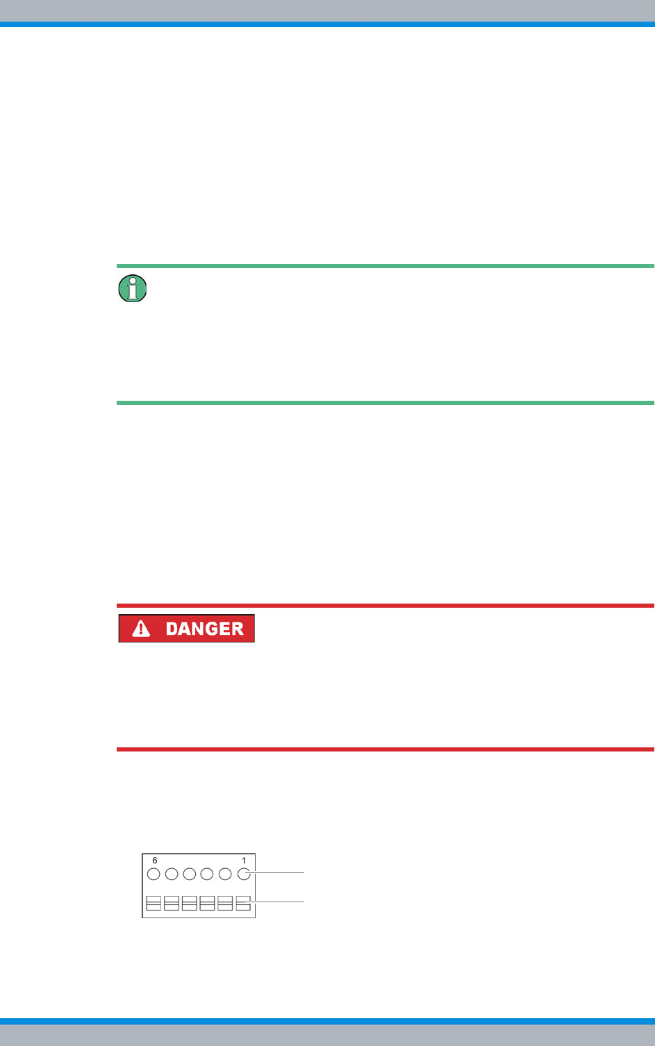
DIB-500 R4.1 Component replacement
Replacing components of the VAC and alarm system expansion – optional
198 Installation, Operation and Service Manual 90DIB500R41IM_FCC02 – 99.1
Disconnecting external alarms (via alarm input/output module)
Before replacing the mounting frame, the external alarms connected to the alarm input/
output module must be disconnected. The alarm input/output module is installed in a
mounting frame.
If an external alarm is not connected, alarm jumpers are installed between the terminals
of the alarm inputs in the condition as supplied to the customer to short-circuit the con-
tacts. If installed, these alarm jumpers must additionally be removed when external
alarms are disconnected. The removed alarm jumpers will be required again when
external alarms are reconnected.
Documentation of the specific pin assignment
During commissioning the external alarms were connected depending on the desired
alarm signalling. Before disconnecting the external alarms, ensure that the pin assign-
ment is documented properly to be able to restore the original state following the
replacement.
Proceed as follows to disconnect external alarms:
Preparation:
✓The network element must have been put out of operation temporarily, refer to sec-
tion 8.1 on page 163.
✓The preparatory tasks must have been performed, refer to section 11.8.2.1 on
page 197.
✓The tools and aids must be available, refer to section 11.2.6 on page 174.
✓The pin assignment of the external alarms must be documented for reconnection.
Carry out the following steps:
Risk of electric shock
Electric shock when touching live parts. Hardware components in the equipment cabi-
net are live.
➔When performing work in the equipment cabinet, ensure that the voltage source on
site is switched off. This must have been checked with a voltmeter.
1. Remove the safeguard/s that protect the connected cables in the equipment rack
against tensile strain such as cable ties.
2. Cautiously press the lever (1) downward to open the clamps of the connectors (2),
refer to Figure 11.16.
Figure 11.16 Alarm input/output module - connection
2
1
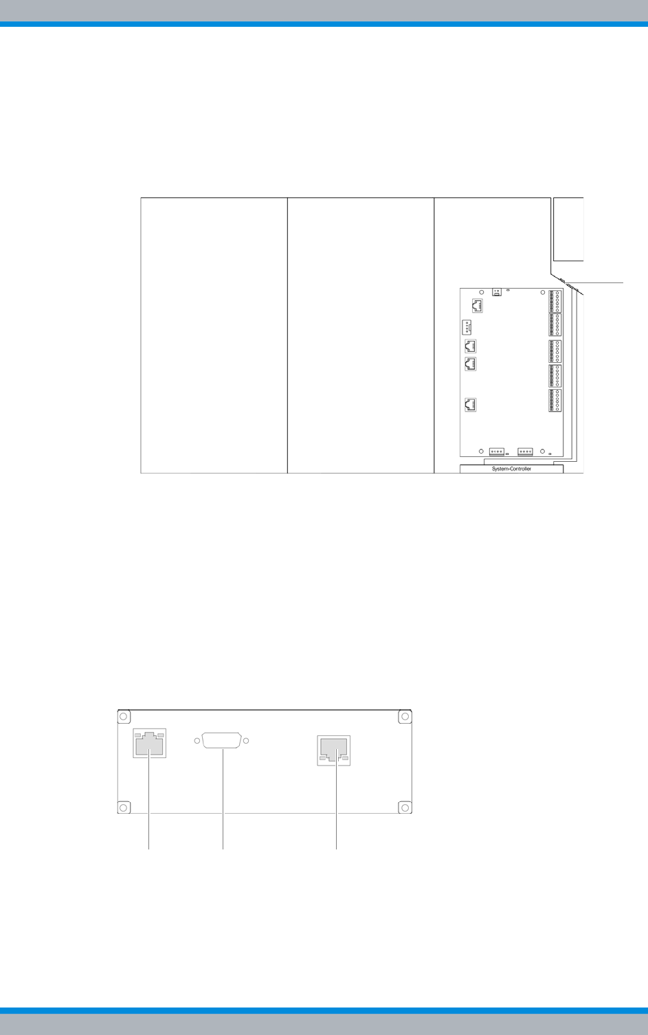
Installation, Operation and Service Manual 90DIB500R41IM_FCC02 – 99.1 199
DIB-500 R4.1 Component replacement
Replacing components of the VAC and alarm system expansion – optional
3. Remove the wires of the external alarms from the corresponding clamps of the
alarm input/output module, refer to Figure 11.16 on page 198.
4. Remove any installed alarm jumpers (3), refer to Figure 11.16 on page 198. You
will need them again.
5. Route the cables of the external alarms through the corresponding grommet, refer
to Figure 11.17.
Figure 11.17 Mounting frame grommet (top view)
6. Secure the wires of the external alarms against short circuit.
7. Fasten the cables of the external alarms accordingly in/on the equipment rack.
✓You have successfully disconnected external alarms.
Removing connections of the SC200
The connections to the SC200 must have been removed to be able to replace the
mounting frame.
Figure 11.18 shows the rear view of the system controller. The following table describes
these in detail.
Figure 11.18 Rear view of system controller
1 2 3
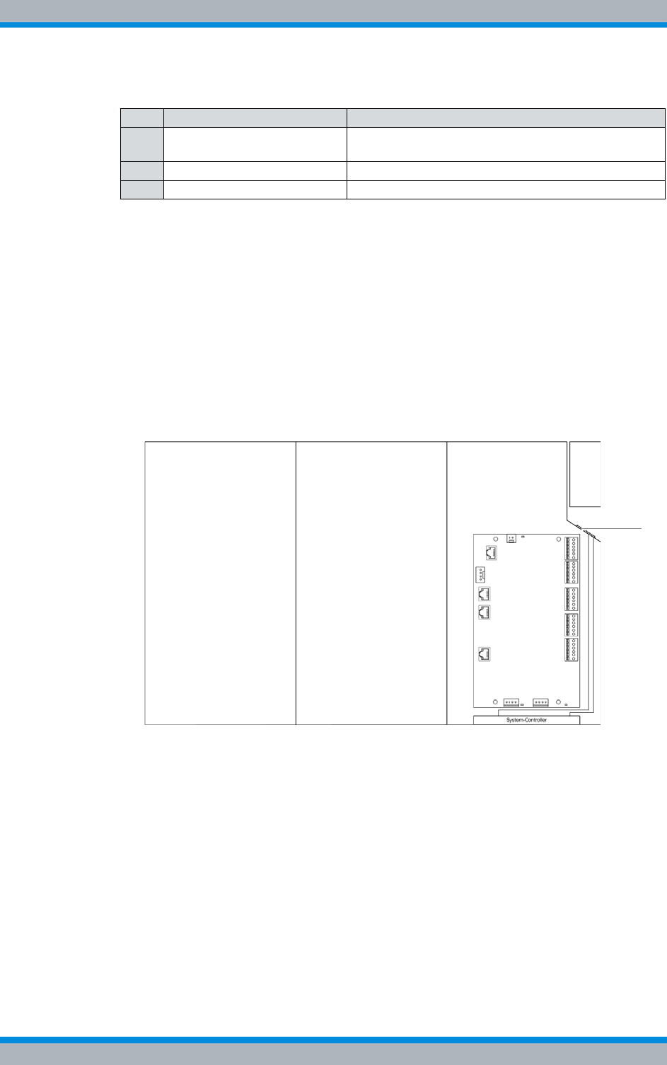
DIB-500 R4.1 Component replacement
Replacing components of the VAC and alarm system expansion – optional
200 Installation, Operation and Service Manual 90DIB500R41IM_FCC02 – 99.1
Proceed as follows to remove connections:
Preparation:
✓The network element must have been put out of operation temporarily, refer to sec-
tion 8.1 on page 163.
✓The preparatory tasks must have been performed, refer to section 11.8.2.1 on
page 197.
✓The connecting cables must be marked for reconnection.
Carry out the following steps:
1. Remove the cables (1) and (3) from the rear of the SC200, refer to Figure 11.18 on
page 199.
2. Route the cables through the appropriate grommets, refer to Figure 11.19.
Figure 11.19 Mounting frame grommet (top view)
3. Fasten the cables appropriately in/on the equipment rack.
✓You have successfully removed connections.
Removing Plugs with Earthing Contact – optional (only for VAC expansion)
If the integrated rectifier module(s) is/are equipped with a plug/plugs with earthing con-
tact, they must be removed before use.
Table 11.27 Legend: rear view of system controller
No. Constituent Description
1 Ethernet interface Ethernet interface to the first TIB of the equipment
rack (TIB A, LAN 1).
2 Serial interface not used for the time being
3 Supply voltage connection Supply voltage connection of the system controller

Installation, Operation and Service Manual 90DIB500R41IM_FCC02 – 99.1 201
DIB-500 R4.1 Component replacement
Replacing components of the VAC and alarm system expansion – optional
Connection to a Fixed Connection
The plug with earthing contact can be removed when the DIB-500 R4.1 system is to be
connected to a fixed connection (e. g. distributor box). In this case, the strand ends of
the voltage supply cable/s must be fitted with end sleeves for strands.
Proceed as follows to remove a plug/plugs with earthing contact:
Preparation:
✓The network element must have been put out of operation temporarily, refer to sec-
tion 8.1 on page 163.
Carry out the following steps:
➔Remove the plug(s) with earthing contact using the tool required for this purpose.
✓You have successfully removed a plug/plugs with earthing contact.
11.8.2.2 Replacing the mounting frame and the SC200
Before replacing the mounting frame, the corresponding connections must be removed
to be able to install/remove the mounting frame. The SC200 is always replaced together
with the mounting frame.
Removing the mounting frame
The SC200 and the alarm input/output module are installed in the mounting frame. With
VAC voltage supply, additional rectifier modules have been installed that need to be
removed before removing the mounting frame.
Depending on the variant (VDC-/VAC voltage supply, optionally additional alarming unit),
a grounding cable, the DC voltage supply cable from the terminal block and the AC volt-
age supply cable(s) are connected to the mounting frame.
Proceed as follows to remove the mounting frame:
Preparation:
✓The network element must have been put out of operation temporarily, refer to sec-
tion 8.1 on page 163.
✓The tools and aids must be available, refer to section 11.2.6 on page 174.
✓The preparatory tasks must have been performed, refer to section 11.8.2.1 on
page 197.
✓The rectifier module(s) must have been removed, refer to section 11.8.1.1 on
page 193.
Carry out the following steps:
1. Remove all cable ties and strain relief devices of the AC voltage supply cable/s.
2. Route the AC voltage supply cable/s appropriately through the equipment rack so
that it does not/they do not get in the way when removing the mounting frame later
on.
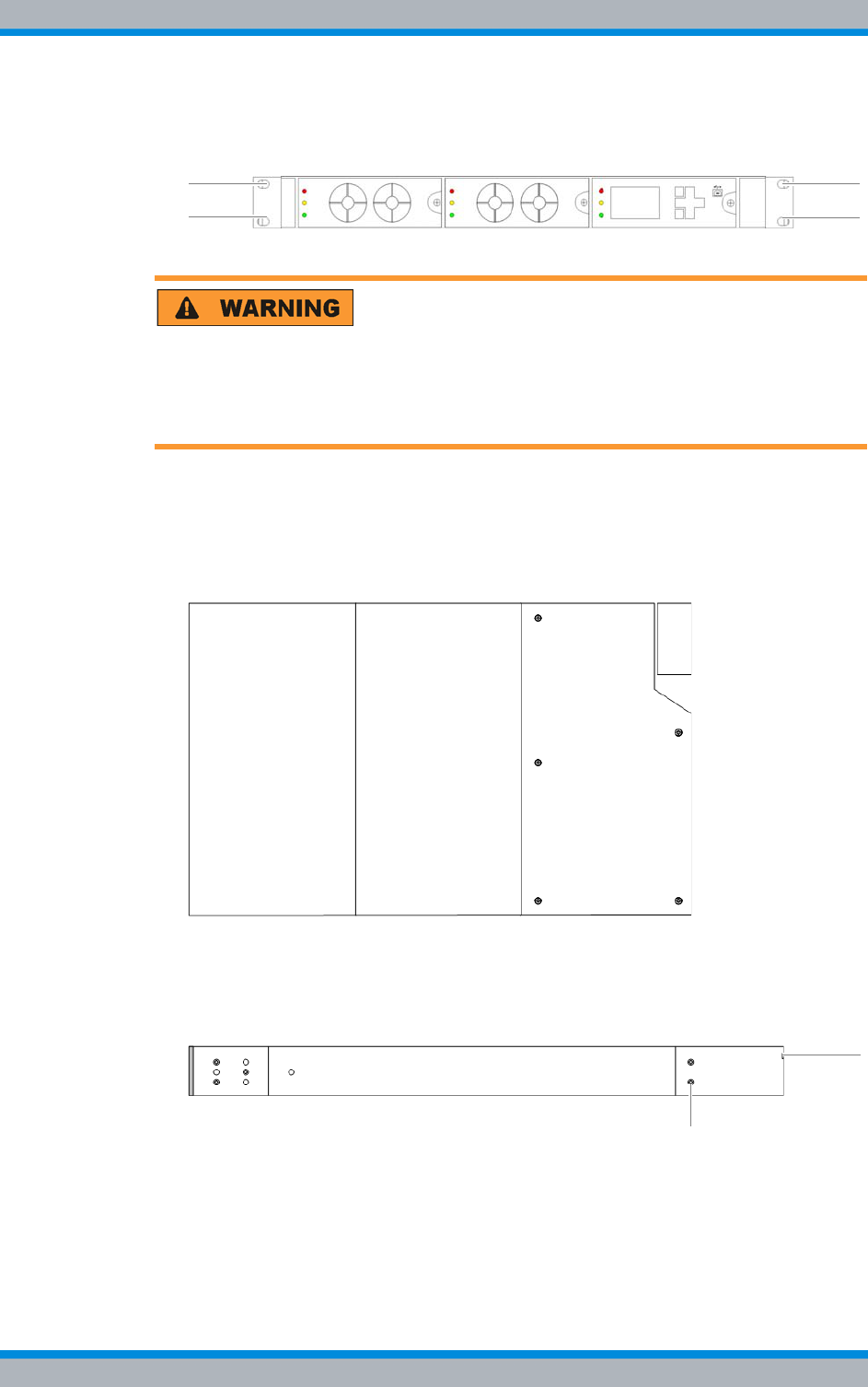
DIB-500 R4.1 Component replacement
Replacing components of the VAC and alarm system expansion – optional
202 Installation, Operation and Service Manual 90DIB500R41IM_FCC02 – 99.1
3. Loosen the mounting screws of the retaining brackets on the front of the equipment
rack using a Torx screwdriver size TX 20 x 80, refer to Figure 11.20.
Figure 11.20 Mounting frame mounting screws
Risk of injury
The equipment rack features sharp edges on the inside. Risk of injury if you do not wear
protective gloves.
➔Always wear protective gloves for the following process steps.
4. Cautiously pull the component out of the subrack until the cover of the VDC voltage
supply connectors on the side of the component is accessible, refer to Figure
11.21.
Figure 11.21 Mounting frame – cover of the DC voltage supply connectors (top view)
5. Loosen the nut of the earthing connector using a size 10 wrench.
6. Loosen the mounting screws of the DC voltage supply connector cover using a
size 1 cross-head screwdriver, refer to Figure 11.22.
Figure 11.22 Mounting frame – cover of the DC voltage supply connectors (side view)
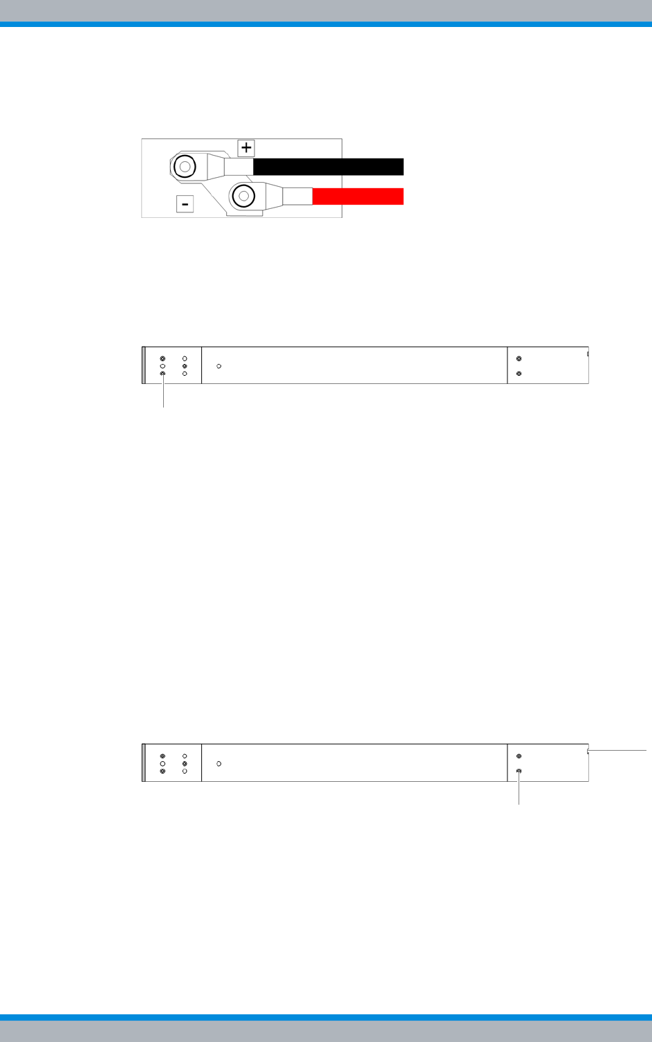
Installation, Operation and Service Manual 90DIB500R41IM_FCC02 – 99.1 203
DIB-500 R4.1 Component replacement
Replacing components of the VAC and alarm system expansion – optional
7. Loosen the nut of the DC voltage supply cables using a size 4 wrench, refer to Fig-
ure 11.23.
Figure 11.23 Mounting frame – DC voltage supply connectors (side view)
8. Remove the DC voltage supply cables.
9. Pull the component out of the subrack cautiously.
10. Remove the retaining brackets from the component by loosening the fastening
screws using a size 1 cross-head screwdriver. The retaining brackets will be
required when installing the component again.
Figure 11.24 Mounting frame – retaining brackets (side view)
✓You have successfully removed the mounting frame.
Preparing the mounting frame
Before installing the mounting frame, the frame must be prepared appropriately. For this
purpose, part of the replacement cover of the DC voltage supply connectors must be
broken off along the predetermined breaking pattern.
Proceed as follows to prepare the mounting frame:
Preparation:
✓The upper cover of the mounting frame must have been removed, refer to section
5.12.1 on page 124.
✓The tools and aids must be available, refer to section 11.2.6 on page 174.
Carry out the following steps:
1. Loosen the mounting screws of the DC voltage supply connector cover using a
size 1 cross-head screwdriver..
Figure 11.25 Mounting frame – cover of the DC voltage supply connectors (side view)

DIB-500 R4.1 Component replacement
Replacing components of the VAC and alarm system expansion – optional
204 Installation, Operation and Service Manual 90DIB500R41IM_FCC02 – 99.1
Risk of injury
The equipment rack features sharp edges on the inside. Risk of injury if you do not wear
protective gloves.
➔Always wear protective gloves for the following process steps.
2. Brake off the rear part of the cover along the predetermined breaking pattern. Use
combination pliers for this purpose.
Figure 11.26 Cover of the DC voltage supply connectors - predetermined breaking pattern (rear
view)
3. Deburr the edges of the predetermined breaking pattern. Use a file for this pur-
pose.
✓You have successfully prepared the mounting frame.
Installing the mounting frame
When installing the mounting frame, it must be reconnected to the grounding cable and
the DC voltage supply cables. With VAC-voltage supply, the removed rectifier modules
must be installed again.
Proceed as follows to install the mounting frame:
Preparation:
✓The network element must have been put out of operation temporarily, refer to sec-
tion 8.1 on page 163.
✓The preparatory tasks must have been performed, refer to 11.8.2.1 on page 197.
✓The tools and aids must be available, refer to section 11.2.6 on page 174.
✓The mounting frame must have been prepared appropriately, refer to section on
page 203.
✓You need the mounting screws removed with the component.
✓You need the retaining brackets removed with the component.
✓You need the cover of the DC voltage supply connectors you dismounted when
removing the component.
Carry out the following steps:
1. Install the removed retaining brackets again, refer to Figure 11.24.
2. Route the AC voltage supply cable/s appropriately through the equipment rack so
that it does not/they do not get in the way when installing the mounting frame later
on.

Installation, Operation and Service Manual 90DIB500R41IM_FCC02 – 99.1 205
DIB-500 R4.1 Component replacement
Replacing components of the VAC and alarm system expansion – optional
Strain relief of connected cables / connecting lines
When connecting cables and connecting lines, you must ensure that they are protected
against tensile strain.
3. Fasten the connected cables in the equipment rack in such a way that they are pro-
tected against tensile strain, e. g. by using cable ties.
Risk of injury
The equipment rack features sharp edges on the inside. Risk of injury if you do not wear
protective gloves.
➔Always wear protective gloves for the following process steps.
4. Position the component.
5. Cautiously slide the component into the subrack from the front until the grounding
cable and the DC voltage supply cables reach up to the connectors on the side of
the component.
6. Reconnect the grounding cable properly.
7. Retighten the nut of the grounding cable. Use a size 10 wrench for this purpose.
8. Route the DC voltage supply cables through the corresponding grommet of the DC
voltage supply connector cover.
9. Properly reconnect all the cables to the component.
10. Retighten the nut of the DC voltage supply cable. Use a size 4 wrench for this pur-
pose.
11. Mount the cover of the DC voltage supply connectors on the mounting frame again,
refer to Figure 11.22 on page 202. Use a size 1 cross-head screwdriver for this pur-
pose.
12. Cautiously slide in the component from the front along the holder until it has com-
pletely engaged.
13. Tighten the mounting screws of the retaining brackets again at the front side of the
equipment rack. Use a Torx wrench size TX10 20 x 80 for this purpose.
Strain relief of connected cables / connecting lines
When connecting cables and connecting lines, you must ensure that they are protected
against tensile strain.
14. Fasten the connected cables in the equipment rack in such a way that they are pro-
tected against tensile strain, e. g. by using cable ties.
15. Reinstall the rectifier module/s, see section 11.8.1.2 on page 195.
✓You have successfully installed the mounting frame.
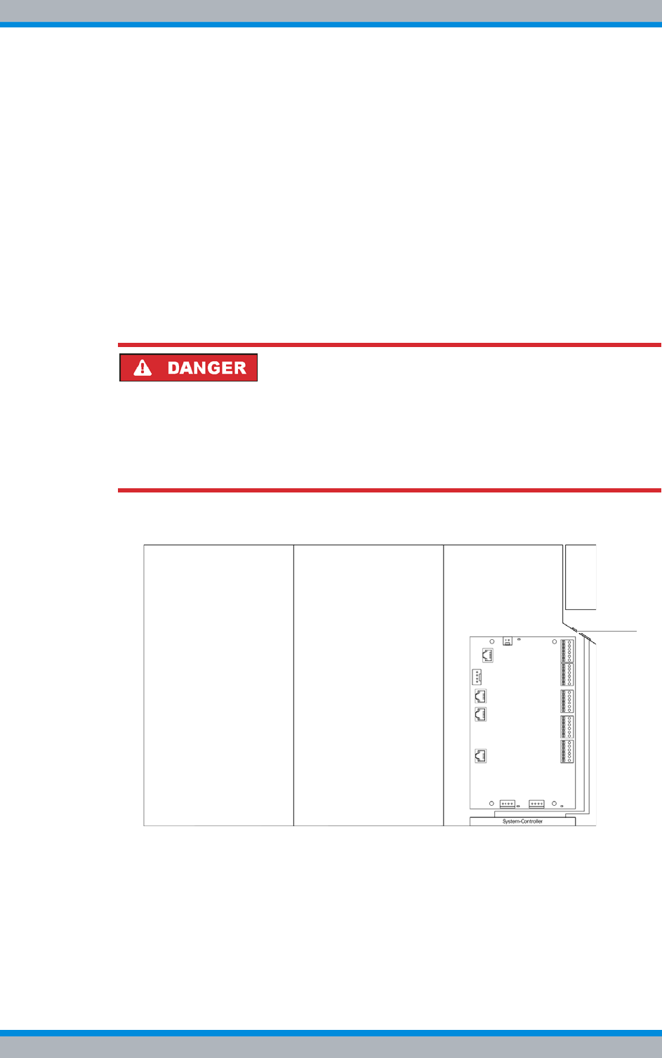
DIB-500 R4.1 Component replacement
Replacing components of the VAC and alarm system expansion – optional
206 Installation, Operation and Service Manual 90DIB500R41IM_FCC02 – 99.1
Attaching connectors of the SC200
The SC200 connections must be installed prior to connecting the external alarms.
Proceed as follows to install the connections:
Preparation:
✓The network element must have been put out of operation temporarily, refer to sec-
tion 8.1 on page 163.
✓The voltage source on site must be switched off. This must have been checked
with a voltmeter
✓The preparatory tasks must have been performed, refer to section 11.8.2.1 on
page 197.
✓The tools and aids must be available, refer to section 11.2.6 on page 174.
Carry out the following steps:
Risk of electric shock
Electric shock when touching live parts. Hardware components in the equipment cabi-
net are live.
➔When performing work in the equipment cabinet, ensure that the voltage source on
site is switched off. This must have been checked with a voltmeter.
1. Route the cables through the appropriate grommets, refer to Figure 11.27.
Figure 11.27 Mounting frame grommet (top view)
2. Reconnect all the cables properly to the rear of the component, refer to Figure
11.18 on page 199.
Installation, Operation and Service Manual 90DIB500R41IM_FCC02 – 99.1 207
DIB-500 R4.1 Component replacement
Replacing components of the VAC and alarm system expansion – optional
Strain relief of connected cables / connecting lines
When connecting cables and connecting lines, you must ensure that they are protected
against tensile strain.
3. Fasten the connected cables in the equipment rack in such a way that they are pro-
tected against tensile strain, e. g. by using cable ties.
✓You have successfully installed the connections.
11.8.2.3 Concluding tasks
To complete the replacement of the mounting frame, the tasks listed in the following
table must be performed.
Installing Plugs with Earthing Contact – optional (only for VAC expansion)
With a VAC voltage supply, the DIB-500 R4.1 system can be connected to the voltage
source on site via the following connection variants:
|to a fixed connection (e. g. distributor box),
|or with a plug with earthing contact to a mains socket.
If the integrated rectifier module(s) is/are to be operated with a plug/plugs with earthing
contact, the corresponding plugs with earthing contact in compliance with CEE 7/VII
must be mounted on the corresponding voltage supply cables.
Mounting plugs with earthing contact
The required mounting of plugs with earthing contact- especially of the grounding cable
(grounding conductor) - may vary depending on the country of use and the mains
socket.
Table 11.28 Overview of finalising tasks (Replacing the mounting frame and the SC200)
Tasks/work steps Described in
Installing Plugs with Earthing Contact – optional (only for VAC expan-
sion) on page 207
Mounting the top cover of the mounting frame Section 5.12.3 on
page 128
Mounting the top cover of the equipment rack Section 5.13 on
page 129
Recommissioning after a temporary service interruption Section 9.1 on
page 167
Configuring the SC200 Section 11.8.2.4 on
page 208
Function tests and operating surveillance Chapter 7 on
page 151
DIB-500 R4.1 Component replacement
Replacing components of the VAC and alarm system expansion – optional
208 Installation, Operation and Service Manual 90DIB500R41IM_FCC02 – 99.1
Proceed as follows to mount a plug/plugs with earthing contact:
Preparation:
✓The network element must have been put out of operation temporarily, refer to sec-
tion 8.1 on page 163.
Carry out the following steps:
➔Mount the plug(s) with earthing contact on the corresponding voltage supply
cable(s) using the tool required for this purpose.
✓You have successfully mounted a plug/plugs with earthing contact.
11.8.2.4 Configuring the SC200
To ensure proper operation of the SC200, it must be configured accordingly. Following
the configuration of the IP settings, all the other configuration parameters can be loaded
via the "SC200-def_cfg_XXXX-XX-XX.dcc" (XXXX-XX-XX corresponds to the date)
configuration file of the S200.
When delivered as a spare part, the SC200 will not yet be configured. In this case, you
have to perform the configuration tasks described below.
Table 11.29 describes the possible states of the SC200. Depending on the configuration
level, the SC200 needs to be configured following a replacement of the mounting frame.
The tasks listed in the following table must be performed for the configuration of the
SC200.
Table 11.29 State of the replacement component
State Configuration required
Spare part x
Replacement part, e. g. from an already available
DIB-500 R4.1 system ---
Table 11.30 Overview of the tasks to be performed (Configuring the SC200)
Tasks/work steps Described in
Installing the "DCTools" application on page 209
Configuring the orientation of the SC200 display window (local) on page 209
Configuring IP settings of the SC200 (local) on page 211
Loading the SC200 configuration file (via the "DCTools" application) on page 213
Uninstalling the "DCTools" application on page 218

Installation, Operation and Service Manual 90DIB500R41IM_FCC02 – 99.1 209
DIB-500 R4.1 Component replacement
Replacing components of the VAC and alarm system expansion – optional
Installing the "DCTools" application
The system controller is configured via the "DCTools" application on the SC200. For this
purpose, the application must be installed via a setup wizard. The installation file
(Setup) and the configuration file of the SC200 are available on the PV-DVD.
Table 11.31 describes the directory structure of the PV-DVD for the "DCTools" applica-
tion.
Proceed as follows to install the "DCTools" application:
Preparation:
✓The service computer must have been started.
✓Any other applications running in the background must have been closed.
✓The installation file must be available.
Carry out the following steps:
1. Start the Setup Wizard by double-clicking on the installation file and following the
instructions during the course of the installation.
➥The "DCTools" application has been installed, started and will be displayed in the
Windows task bar.
✓The installation has been completed.
Configuring the orientation of the SC200 display window (local)
When delivered as a spare part, the SC200 will not yet be configured. In the delivery
status, the orientation of the display window in the mounting frame will not be config-
ured. To be able to operate the SC200 properly, the orientation of the display window
must be configured.
The orientation of the SC200 display window must be configured via the controls of the
SC200.
Table 11.31 Directory structure of the PV-DVD – "DCTools" application
Directory Subdirec-
tory Content description
software dctools This subdirectory holds all the data required for the "DCTools"
application:
|The installation file of the "DCTools application:
"DCTools-X.X.X-Installer.EXE" (X.X.X corresponds to the
version number)
|Configuration file of the SC200:
"SC200-def_cfg_XXXX-XX-XX.dcc" (XXXX-XX-XX corre-
sponds to the date)
|The Product Release Note of the "DCTools" application:
"PRN0067_A DCTools Version X-X-X.pdf" (X.X.X corre-
sponds to the version number)
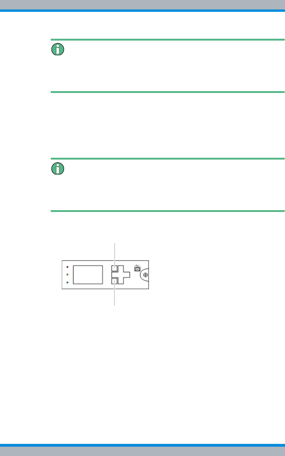
DIB-500 R4.1 Component replacement
Replacing components of the VAC and alarm system expansion – optional
210 Installation, Operation and Service Manual 90DIB500R41IM_FCC02 – 99.1
Controls of the SC200
When delivered as a spare part, the SC200 will not yet be configured. Once the config-
uration file of the SC200 has been loaded, the controls of the SC200 will be disabled to
prevent configuration adaptations.
Configuring the orientation of the display window of the SC200
Preparation:
✓The voltage source on site must be switched on. This must have been checked
with a voltmeter.
✓The network element must be switched on.
Carry out the following steps:
Using softkeys
The respective function depends on the display in the display window. Softkey 1 is used
to call menus and save settings. Softkey 2 is used to call superordinate menus and dis-
card settings.
1. Press softkey 1 to open the main menu, refer to Figure 11.28 on page 210.
Figure 11.28 SC200 – Softkeys
➥The main menu will be displayed.
2. Press the navigation button downward twice to navigate to the Settings menu.
3. Press softkey 1 to open the main menu.
➥The Settings menu will be displayed.
4. Press the navigation button downward once to navigate to the Setup menu.
5. Press softkey 1 to open the main menu.
➥The Setup menu will be displayed.
6. Press the navigation button downward four times to select the Orientation setting.
7. Press softkey 1 to open the main menu.
➥The Orientation menu will be displayed.
8. Select the Set to Horizontal setting.
➥The orientation will change.
9. Press softkey 1 to save the setting.
1
2

Installation, Operation and Service Manual 90DIB500R41IM_FCC02 – 99.1 211
DIB-500 R4.1 Component replacement
Replacing components of the VAC and alarm system expansion – optional
10. Press softkey 2 to exit the settings.
11. Press softkey 2 twice to exit the main menu.
✓You have successfully configured the display window of the SC200.
Configuring IP settings of the SC200 (local)
For the proper operation, each SC200 should have corresponding IP settings. The IP
settings will not have been configured upon delivery of the replacement component.
Table 11.32 shows the IP settings that have to be configured for the SC200.
The IP settings must be configured via the controls of the SC200.
Controls of the SC200
When delivered as a spare part, the SC200 will not yet be configured. Once the config-
uration file of the SC200 has been loaded, the controls of the SC200 will be disabled to
prevent configuration adaptations.
Configuring the IP settings of the SC200
Preparation:
✓The voltage source on site must be switched on.
✓The network element must be switched on.
Table 11.32 IP settings of SC200
Setting Value
IP address – "IP Address" setting 10.255.255.301)
1) When using the SC200 in the second equipment rack with more than four carriers:
10.255.255.29
Network mask – "Subnet Mask" setting 10.255.255.0
Gateway (default gateway) – "Gateway Address"
setting 10.255.255.1
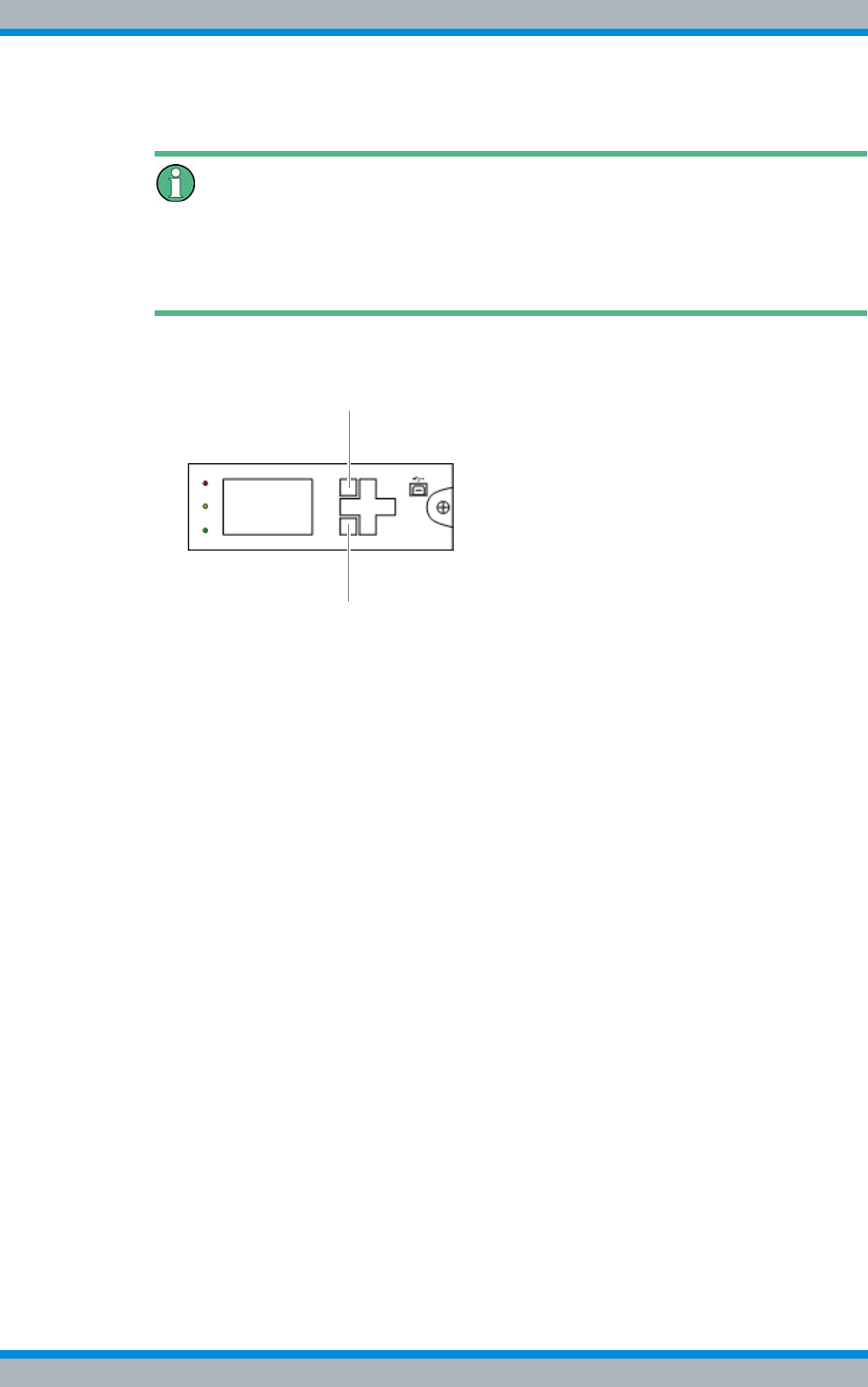
DIB-500 R4.1 Component replacement
Replacing components of the VAC and alarm system expansion – optional
212 Installation, Operation and Service Manual 90DIB500R41IM_FCC02 – 99.1
Carry out the following steps:
Using softkeys
The respective function depends on the display in the display window. Softkey 1 is used
to call menus and save settings. Softkey 2 is used to call superordinate menus and dis-
card settings.
1. Press softkey 1 to open the main menu, refer to Figure 11.29 on page 212.
Figure 11.29 SC200 – Softkeys
➥The main menu will be displayed.
2. Press the navigation button downward twice to navigate to the Settings menu.
3. Press softkey 1 to open the main menu.
➥The Settings menu will be displayed.
4. Press the navigation button downward once to navigate to the Setup menu.
5. Press softkey 1 to open the main menu.
➥The Setup menu will be displayed.
6. Press the navigation button downward once to select the IP Address setting.
➥The first group of digits is marked, e.g. 10.255.253.30.
7. Use the "up" and "down" navigation buttons to set the respective value.
8. Use the "left" and "right" navigation buttons to switch between the groups of digits.
9. Set the corresponding IP address, refer to Table 11.33 on page 213.
10. Press softkey 1 to save the settings.
11. Press softkey 2 to exit the settings.
12. Proceed analogously to configure the Subnet Mask settings, refer to Table 11.33 on
page 213.
13. Proceed analogously to configure the gateway Address settings, refer to Table
11.33 on page 213.
14. Press softkey 2 twice to exit the main menu.
✓You have completed configuring the IP settings of the SC200.
1
2
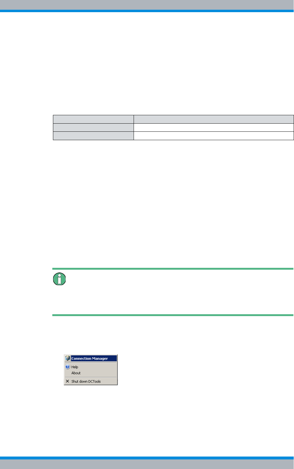
Installation, Operation and Service Manual 90DIB500R41IM_FCC02 – 99.1 213
DIB-500 R4.1 Component replacement
Replacing components of the VAC and alarm system expansion – optional
Loading the SC200 configuration file (via the "DCTools" application)
The configuration file of the SC200 contains an adapted configuration for operation in
the DIB-500 R4.1. The configuration file is loaded via the application "DCTools".
Upon the first start of the "DCTools" application, a new connection must be established
and configured accordingly.
Table 11.33 shows the required settings of the new connection to the SC200. For all the
other properties you can accept the default values.
Loading the configuration file of the SC200:
Preparation:
✓The network element must be switched on.
✓The IP settings of the SC200 must have been configured.
✓The IP address of the service computer must be in the same subnet as the network
element to be updated, refer to Table 11.32 on page 211.
✓The "DCTools" application must have been installed.
✓The configuration file of the SC200 must be available.
✓The service computer must have been connected, refer to section 6.1.2.1 on
page 133.
Carry out the following steps:
1. Start the "DCTools" application via the corresponding entry on the Windows Start
menu or, for example via a shortcut on the Windows desktop, if installed.
➥The Welcome to DCTools dialogue will open.
Don't show again
Enable (check) this checkbox if you do not want this dialogue to be displayed again in
future actions.
➥The application has been started and will be displayed in the Windows task bar.
2. Click the corresponding icon in the Windows task bar.
3. Click the Connection Manager item:
Figure 11.30 Windows task bar – Connection Manager item
➥The Connection List window will be displayed.
Table 11.33 Required settings of the new connection to the SC200
Property Required setting
Connection Name Any
Server IP Address 10.255.255.30
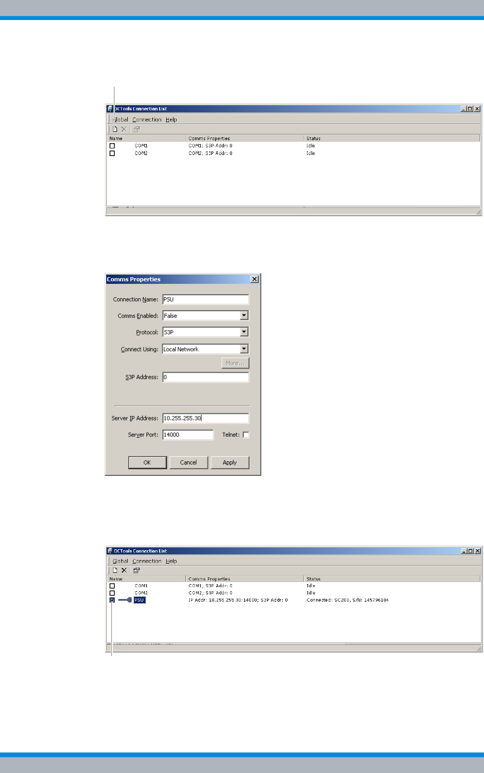
DIB-500 R4.1 Component replacement
Replacing components of the VAC and alarm system expansion – optional
214 Installation, Operation and Service Manual 90DIB500R41IM_FCC02 – 99.1
4. Click the Create a new connection (Ins) button to create a new connection.
Figure 11.31 "DCTools" application – "Create a new connection (Ins)" button
➥The Comms Properties dialogue box will be displayed.
5. Enter the required settings, refer to Table 11.33 on page 213.
Figure 11.32 "DCTools" application – required settings
6. Click OK to save the settings.
➥The connection will be created.
7. Click the checkbox to establish the connection.
Figure 11.33 "DCTools" application – establish connection
➥The connection to the SC200 is being established.
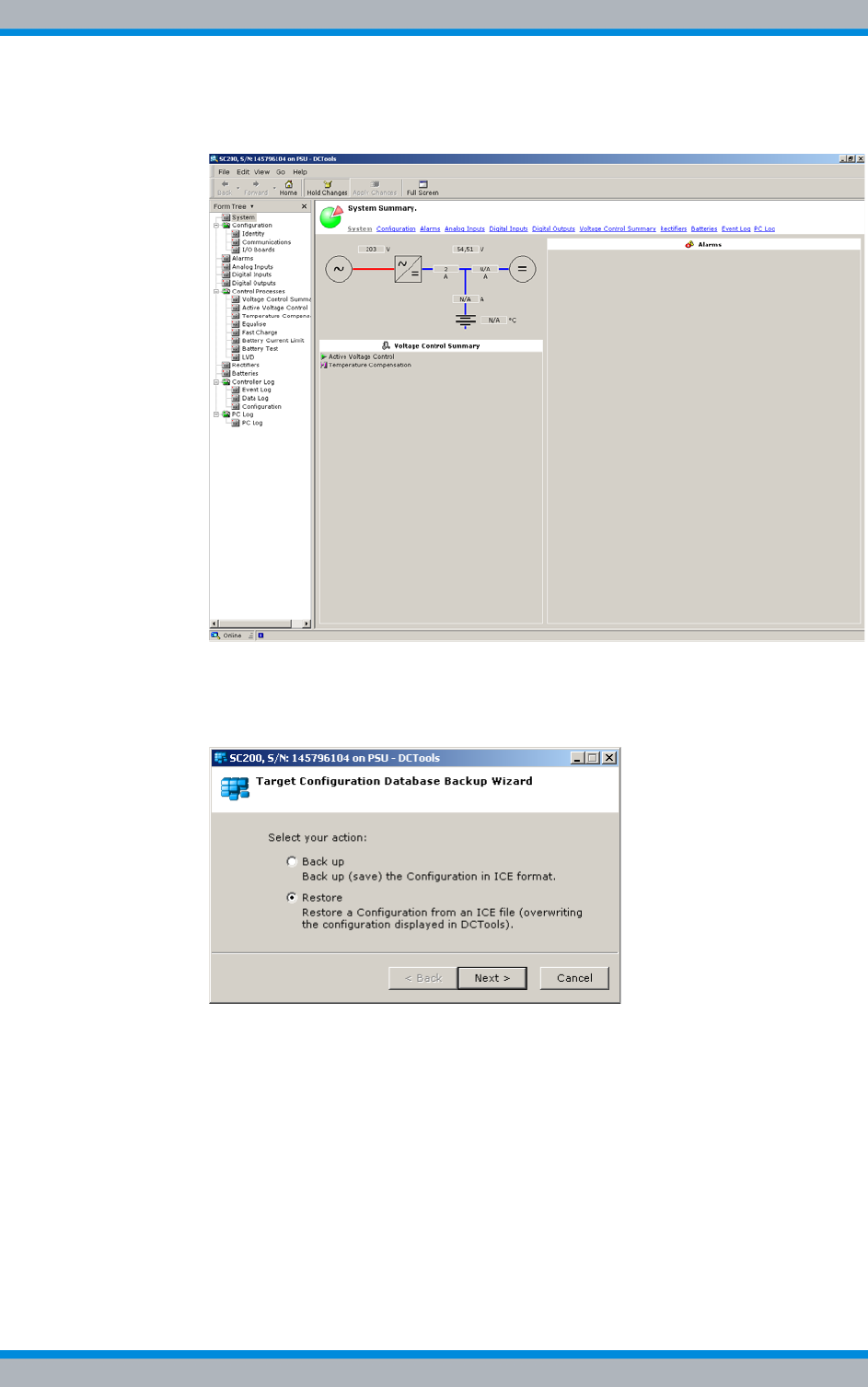
Installation, Operation and Service Manual 90DIB500R41IM_FCC02 – 99.1 215
DIB-500 R4.1 Component replacement
Replacing components of the VAC and alarm system expansion – optional
➥The application window of the "DCTools" application opens:
Figure 11.34 "DCTools" application – connection established
8. In the menu, click on File > ICE Backup/Restore.
➥The following dialogue box will be displayed:
Figure 11.35 "DCTools" application – "Target Configuration ..." dialogue box
9. Select the Restore item.
10. Click Next >.
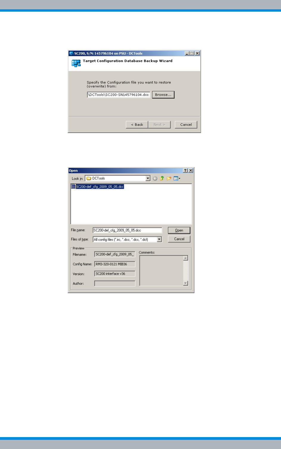
DIB-500 R4.1 Component replacement
Replacing components of the VAC and alarm system expansion – optional
216 Installation, Operation and Service Manual 90DIB500R41IM_FCC02 – 99.1
➥The following dialogue box will be displayed:
Figure 11.36 "DCTools" application – "Target Configuration ..." dialogue box
11. Click Browse to select the configuration file of the SC200.
➥The following dialogue box will be displayed:
Figure 11.37 "DCTools – "Open" dialogue box
12. Navigate to the configuration file of the SC200, refer to Table 11.31 on page 209.
13. Select the configuration file.
14. Click Open to open the configuration file.
➥The configuration file will be opened and the corresponding configuration param-
eters will be loaded.
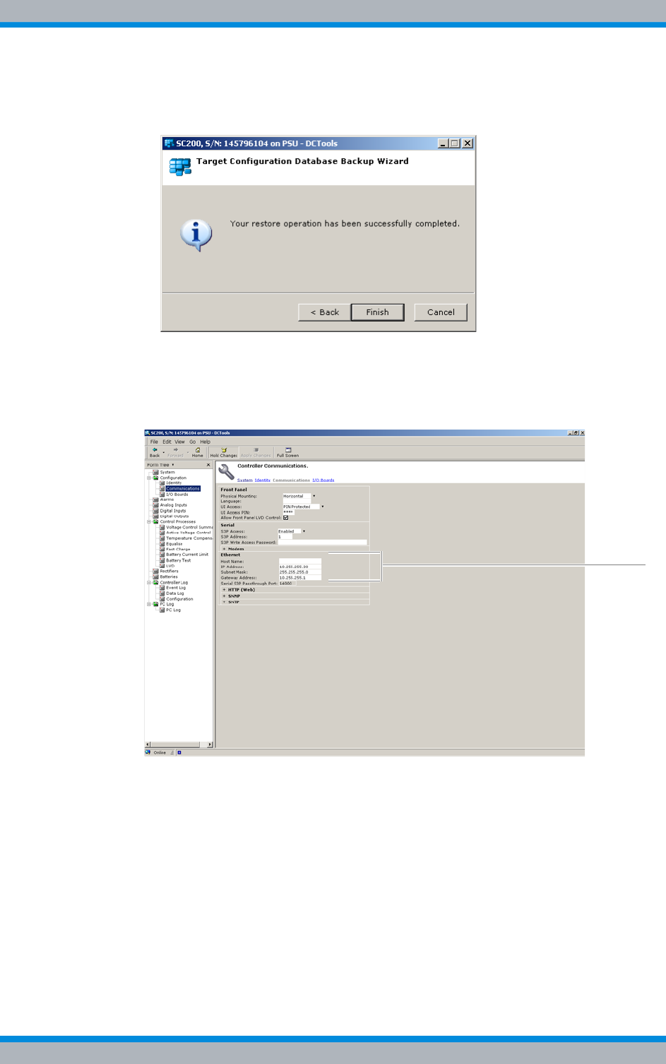
Installation, Operation and Service Manual 90DIB500R41IM_FCC02 – 99.1 217
DIB-500 R4.1 Component replacement
Replacing components of the VAC and alarm system expansion – optional
➥The following dialogue box will be displayed after the configuration files have
been loaded successfully:
Figure 11.38 "DCTools" application – "Target Configuration ..." dialogue box
15. Click Finish to close the dialogue box.
16. In the Form Tree area of the application window, navigate to the level Configuration
> Communications, refer to Figure 11.39:
Figure 11.39 "DCTools" application – "Ethernet" area
17. Check the settings of the Ethernet area, refer to Table 11.33 on page 213.
18. Exit the application.
✓You have successfully loaded the configuration file of the SC200.

DIB-500 R4.1 Component replacement
Replacing cavity couplers – optional (cavity variants only)
218 Installation, Operation and Service Manual 90DIB500R41IM_FCC02 – 99.1
Uninstalling the "DCTools" application
The "DCTools" application facilitates extensive configuration of the SC200. For this rea-
son, the application must be uninstalled after having configured the SC200 since it is
not needed for the functional operation.
The "DCTools" application can be uninstalled via "Add or Remove Programs" in the
Windows Control Panel.
Proceed as follows to uninstall the "DCTools" application:
Preparation:
✓The installation of the SC200 must have been completed.
✓Administrator rights must have been granted for the respective installation direc-
tory.
Carry out the following steps:
1. Start the Windows Control Panel via the Windows Start Menu > Settings > Control
Panel > Software.
2. Select the "DCTools" application in the list of installed programs and click the
"Remove" button to uninstall the application.
➥The Select Uninstall Method dialogue opens.
3. Ensure that Automatic has been selected and proceed according to the instructions
of the Setup wizard.
✓You have successfully completed the uninstall process.
11.9 Replacing cavity couplers – optional (cavity variants
only)
Depending on the number of carriers, up to two equipment cabinets are used for the
DIB-500 R4.1 in the cavity variant. The cavity couplers (one per carrier) are installed in
the respective equipment cabinet(s) of the DIB-500 R4.1. With more than four carriers,
the equipment racks are positioned next to each other on site and connected with each
other.
The tasks listed in the following table must be performed for the replacement of a cavity
coupler.
Table 11.34 Overview of the tasks to be performed (Replacing cavity couplers – optional (cavity vari-
ants only))
Tasks/work steps Described in
Temporary service interruption Section 8.1 on
page 163
Replacing a cavity coupler Section 11.3.1 on
page 177
Adjusting a cavity coupler – optional (cavity variant only) Section 6.2 on
page 143
Recommissioning after a temporary service interruption Section 9.1 on
page 167

Installation, Operation and Service Manual 90DIB500R41IM_FCC02 – 99.1 219
DIB-500 R4.1 Component replacement
Replacing cavity couplers – optional (cavity variants only)
11.9.1 Replacing a cavity coupler
As many as eight cavity couplers can be installed in a DIB-500 R4.1. Each pair of cavity
coupler is installed on a mounting plate on the front of the equipment rack. Each cavity
coupler is fastened to the mounting plate with four attachment screws from below and
two attachment screws from behind. Four screws fasten the mounting plate to the
equipment cabinet. To remove a cavity coupler, first remove the mounting plate and
then remove the screws fastening the cavity coupler to the mounting plate. The second
(operable) cavity coupler stays attached to the mounting plate.
The following sections describe the removal and installation of a cavity coupler.
Procedure described refers to one cavity coupler
The procedure described in the following refers to one cavity coupler. Depending on the
DIB-500 R4.1 variant, the work steps may have to be repeated for further cavity cou-
plers.
11.9.1.1 Removing a cavity coupler
The procedure for removing a cavity coupler is described in the following.
Proceed as follows to remove a cavity coupler:
Preparation:
✓The tools and aids must be available, refer to section 11.2.7 on page 174.
Carry out the following steps:
1. Switch off the voltage supply by flipping down the On/Off switch, refer to Figure
3.15 on page 43.
Specified cable lengths
All cables have specified lengths and must not be mixed. Mark the removed cables dur-
ing the uninstallation, if necessary, and reconnect the removed cables again to the orig-
inal connection during reinstallation.
Risk of injury
The equipment rack features sharp edges on the inside. Risk of injury if you do not wear
protective gloves.
➔Always wear protective gloves for the following process steps.
2. Disconnect all the cables connected to the component, refer to Figure 3.31 on
page 78.
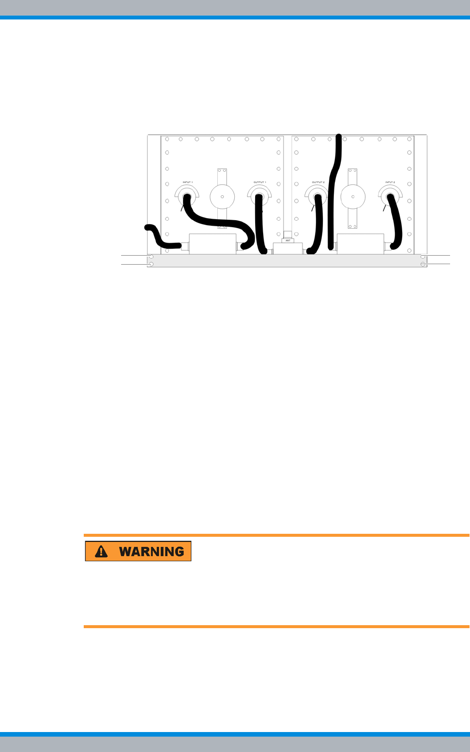
DIB-500 R4.1 Component replacement
Replacing cavity couplers – optional (cavity variants only)
220 Installation, Operation and Service Manual 90DIB500R41IM_FCC02 – 99.1
3. Remove the cables, which lead to the top equipment rack and are connected to the
insulators that are located on the same mounting plate as the respective cavity
coupler, see Figure 3.31 on page 78.
4. Remove the fastening screws of the mounting plate on which the respective cavity
coupler is installed using a size 2 cross-head screwdriver, see Figure 11.40.
Figure 11.40 Attachment screws of the mounting plate
5. Now cautiously pull out the mounting plate with the components fastened to it from
the front of the equipment cabinet along the holder.
6. Remove the fastening screws of the component to be replaced at the underside of
the mounting plate.
7. Remove the fastening screws at the rear side of the cavity coupler with a size 2
cross-head screwdriver
✓You have successfully removed the cavity coupler.
11.9.1.2 Installing the new cavity coupler
The procedure for installing the new cavity coupler is described in the following.
Proceed as follows to install the cavity coupler:
Preparation:
✓The tools and aids must be available, refer to section 11.2.7 on page 174.
✓You need the mounting screws removed with the component.
Carry out the following steps:
Risk of injury
The equipment rack features sharp edges on the inside. Risk of injury if you do not wear
protective gloves.
➔Always wear protective gloves for the following process steps.
1. Install the component on the mounting plate by tightening the corresponding
attachment screws at the rear of the mounting plate again. Use a size 2 cross-head
screwdriver for this purpose.

Installation, Operation and Service Manual 90DIB500R41IM_FCC02 – 99.1 221
DIB-500 R4.1 Component replacement
Replacing the GPS protector – optional
2. Fasten the component on the mounting plate by tightening the corresponding
attachment screws on the underside of the mounting plate again. Use a size 2
cross-head screwdriver for this purpose.
3. Slide the mounting plate with the component fastened on it back in via the front of
the equipment cabinet.
4. Fasten the mounting plate with the component mounted on it on the equipment
rack again, refer to Figure 11.40 on page 220. Use a size 2 cross-head screwdriver
for this purpose.
Specified cable lengths
All cables have specified lengths and must not be mixed. Mark the removed cables dur-
ing the uninstallation, if necessary, and reconnect the removed cables again to the orig-
inal connection during reinstallation.
5. Correctly reconnect all the cables at the front side of the cavity coupler and at the
insulators, Figure 3.31 on page 78.
6. Switch on the power supply again by flipping up the On/Off switch; see Figure 3.15
on page 43.
✓You have successfully installed the cavity coupler.
11.10 Replacing the GPS protector – optional
The GPS protector is a passive and thus maintenance-free hardware component
mounted on the GPS antenna connection of the equipment rack.
Replacing the GPS protector
If you do not have any GPS satellite reception or only restricted reception, the following
function tests should be performed first of all, refer to section 7.6 on page 159. A defec-
tive GPS protector cannot be repaired; it has to be disposed of appropriately.
The tasks listed in the following table must be performed to replace the GPS protector.
Table 11.35 Overview of the tasks to be performed (Replacing the GPS protector – optional)
Tasks/work steps Described in
Temporary service interruption Section 8.1 on
page 163
Removing the GPS protector Section 11.10.1
on page 222
Installing the GPS protector - optional Section 5.9 on
page 117
Connecting antennas Section 5.10 on
page 119
Recommissioning after a temporary service interruption Section 9.1 on
page 167

DIB-500 R4.1 Component replacement
Replacing the GPS protector – optional
222 Installation, Operation and Service Manual 90DIB500R41IM_FCC02 – 99.1
11.10.1 Removing the GPS protector
The procedure for removing the GPS protector is described in the following.
Proceed as follows to remove the GPS protector:
Preparation:
✓The preparatory measures must be completed, refer to Table 11.35 on page 221.
Carry out the following steps:
Risk of damage from electrostatic discharge (ESD)
The DIB-500 R4.1 can be damaged if antennas are connected or disconnected during
the switched-on state. The GPS antenna connection is particularly sensitive to electro-
static discharge (ESD).
➔Ensure that the DIB-500 R4.1 is switched off before connecting or disconnecting
antennas.
1. Remove the GPS antenna cable from the GPS protector.
2. Unscrew the GPS protector from the GPS antenna connector.
✓You have successfully removed the GPS protector.
11.10.2 Installing the GPS protector
The procedure corresponds to the description in section 5.9 on page 117.